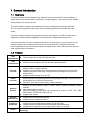
1
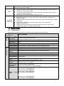
Megapixel Indoor Network Camera User’s Manual Version 4.1.1 Welcome Thank you for purchasing our network camera! This user’s manual is designed to be a reference tool for your system. Please read the following safeguard and warnings carefully before you use this series product! Please keep this user’s manual well for future reference! i Important Safeguards and Warnings 1.Electrical safety All installation and operation here should conform to your local electrical safety codes. The power shall conform to the requirement in the SELV (Safety Extra Low Voltage) and the Limited power source is rated 12V DC or 24V AC in the IEC60950-1. (Refer to general introduction) Please note: Do not connect two power supplying sources to the device at the same time; it may result in device damage! The product must be grounded to reduce the risk of electronic shock. We assume no liability or responsibility for all the fires or electrical shock caused by improper handling or installation. We are not liable for any problems caused by unauthorized modification or attempted repair. 2.Transportation security Heavy stress, violent vibration or water splash are not allowed during transportation, storage and installation. 3.Installation Do not apply power to the camera before completing installation. Please install the proper power cut-off device during the installation connection. Always follow the instruction guide the manufacturer recommended. 4.Qualified engineers needed All the examination and repair work should be done by the qualified service engineers. We are not liable for any problems caused by unauthorized modifications or attempted repair. 5.Environment This series network camera should be installed in a cool, dry place away from direct sunlight, inflammable, explosive substances and etc. Please keep it away from the electromagnetic radiation object and environment. Please make sure the CCD (CMOS) component is out of the radiation of the laser beam device. Otherwise it may result in CCD (CMOS) optical component damage. Please keep the sound ventilation. Do not allow the water and other liquid falling into the camera. Thunder-proof device is recommended to be adopted to better prevent thunder. The grounding studs of the product are recommended to be grounded to further enhance the reliability of the camera. 6. Daily Maintenance ii Please shut down the device and then unplug the power cable before you begin daily maintenance work. Do not touch the CCD (CMOS) optic component. You can use the blower to clean the dust on the lens surface. Always use the dry soft cloth to clean the device. If there is too much dust, please use the water to dilute the mild detergent first and then use it to clean the device. Finally use the dry cloth to clean the device. Please put the dustproof cap to protect the CCD (CMOS) component when you do not use the camera. Dome enclosure is the optical component, do not touch the enclosure when you are installing the device or clean the enclosure when you are doing maintenance work. Please use professional optical clean method to clean the enclosure. Improper enclosure clean method (such as use cloth) may result in poor IR effect of camera with IR function. 7. Accessories Be sure to use all the accessories recommended by manufacturer. Before installation, please open the package and check all the components are included. Contact your local retailer ASAP if something is broken in your package. Accessory Name Amount Network Camera Unit 1 C/CS Adapter ring 1 Quick Start Guide 1 CD 1 iii Table of Contents 1 General Introduction .................................................................................................................. 1 1.1 Overview ........................................................................................................................ 1 1.2 Feature ........................................................................................................................... 1 1.3 Specifications ................................................................................................................ 2 1.3.1 Performance ........................................................................................................... 2 2 Framework ................................................................................................................................... 5 2.1 Rear Panel..................................................................................................................... 5 2.2 Side Panel ..................................................................................................................... 9 2.3 Front Panel .................................................................................................................... 9 2.4 Bidirectional talk.......................................................................................................... 10 2.4.1 Device-end to PC-end ........................................................................................ 10 2.4.2 PC-end to the Device-end.................................................................................. 10 2.5 Alarm Setup................................................................................................................. 10 2.5.1 Alarm Input and Output Connection ................................................................. 11 2.5.2 IR Light Connection............................................................................................. 12 3 Installation.................................................................................................................................. 13 3.1 Lens Installation .......................................................................................................... 13 3.1.1 Auto Aperture Lens ............................................................................................. 13 3.1.2 Manual Lens ......................................................................................................... 13 3.1.3 Remove Lens ....................................................................................................... 14 3.2 SD Card ....................................................................................................................... 14 3.2.1 Installation............................................................................................................. 14 3.2.2 Remove ................................................................................................................. 15 3.3 3G Card........................................................................................................................ 16 3.3.1 Installation............................................................................................................. 16 3.3.2 Remove ................................................................................................................. 16 iv 3.4 3G/WIFI Antenna ........................................................................................................ 17 3.4.1 Installation............................................................................................................. 17 3.4.2 Remove ................................................................................................................. 18 3.5 4 5 6 I/O Port ......................................................................................................................... 19 Quick Configuration Tool......................................................................................................... 20 4.1 Overview ...................................................................................................................... 20 4.2 Operation ..................................................................................................................... 20 Web Operation .......................................................................................................................... 22 5.1 Network Connection................................................................................................... 22 5.2 Login and Main Interface ........................................................................................... 22 FAQ ............................................................................................................................................ 24 Appendix Toxic or Hazardous Materials or Elements ............................................................... 25 v 1 General Introduction 1.1 Overview This series network camera integrates the traditional camera and network video technology. It adopts audio video data collection, transmission, storage together. It can connect to the network directly without any auxiliary device. This series network camera uses standard H.264 video compression technology and PCM, G.711a/u audio compression technology, which maximally guarantees the audio and video quality. This series network camera has mega pixel resolution and supports 12V DC/24V AC power. It supports the wireless network application, bidirectional talk, digital water mark and etc. It can be used alone or used in a network area. When it is used lonely, you can connect it to the network and then use a network client-end. Due to its high definition, multiple functions and various applications, this series network camera is widely used in many indoor environments and other important area surveillance. 1.2 Feature User Management Data Transmission Different user rights for each group, one user belongs to one group. The user right can not exceed the group right. Support cable network data transmission via Ethernet Wireless device supports WIFI/3G wireless data transmission. Storage Function Alarm Function Network Monitor Network Management Peripheral Equipment Power Support central server backup function in accordance with your configuration and setup in alarm or schedule setting Support record via Web and the recorded file are storage in the client-end PC. Support local SD card hot swap. Support short-time storage when encounter disconnection. Support network storage such as FTP. Real-time respond to external on-off alarm input, and video detect as user predefined activation setup and generate corresponding message in screen and audio prompt(allow user to pre-record audio file) Real-time video detect: motion detect, camera masking. Network camera supports one-channel audio/video data transmit to network terminal and then decode. Delay is within 270ms (network bandwidth support needed) Max supports 20 connections. Adopt the following audio and video transmission protocol: HTTP, TCP, UDP, MULTICAST, RTP/RTCP, RTSP and etc. Support web access. Realize network camera configuration and management via Ethernet. Support device management via web. Support various network protocols. Support peripheral equipment connection via the RS232 port, each peripheral equipment control protocol and interface can be set freely. Support serial port (RS232/RS485) transparent data transmission. Support the on-off alarm device to alarm via the sound or the light. External power adapter. Support DC 12V/AC 24V power supply. Warning! 1 PoE Assistant Function Do not connect two power supplying sources to the device at the same time; it may result in device damage! Support Power over Ethernet (PoE). Conform to the IEEE802.3af standard. Connect the device to the switcher or the router that supports the PoE function to realize the network power supply. To guarantee proper performance, please make sure the power sourcing device can supply at least 10W power. Usually, do not use the PoE for the WIFI/3G device. Day/Night mode auto switch (ICR switch.) Backlight compensation: screen auto split to realize backlight compensation to adjust the bright. Support system resource information and running status real-time display. Support log function. Support video watermark function to avoid vicious video modification. Support auto aperture. Support picture parameter setup such as electronic shutter and gain setup. Support dual-stream, ACF(Active frame control ) 1.3 Specifications 1.3.1 Performance System Please refer to the following sheet for network camera performance specification. Model ICIP S1300WDR Parameter Main TI Davinci high performance DSP Processor OS Embedded LINUX System Support real-time network, local record, and remote operation at the same Resources time. User Interface Remote operation interface such as WEB, DSS, PSS System Status SD card status, bit stream statistics, log, and software version. Image Sensor 1/3-inch CMOS 1280(H)×960(V) Pixel Day/Night Support day/night mode switch and IR-CUT at the same time. Mode Auto Aperture Optional Gain Control Fixed/Auto Video Parameter White Balance BLC Electronic Shutter Video Compression Standard Video Rate Frame Manual/Auto Off/BLC/WDR (1-100 adjustable)/HLC(anti-flicker is outdoor and is valid only when exposure mode is auto with range 1-100) Manual/Auto It ranges from 1/3 to 1/10000. H.264/ H.264H/H.264B/MJPEG Note: Some versions do not support H.264H. PAL: Main stream (1280*960@25fps) Extra stream (704*576@25fps) Main stream (1280*720@25fps) Extra stream (704*576@25fps) NTSC: Main stream (1280*960@30fps) Extra stream (704*480@30fps) 2 Main stream (1280*720@30fps) Extra stream (704*480@30fps) Audio Video Bit Rate H.264:56Kbps-8192Kbps, H.264H 16Kbps-8192Kbps, 8192Kbps. MJPEG is adjustable and bit rate is adjustable. Support customized setup. Flip Support Mirror Snapshot Privacy Mask Video Setup Video Information Lens Lens Interface Audio Input Audio Output Bidirectional Talk Input Audio Bit Rate Audio Compression Standard Support Max 1f/s snapshot. File extension name is JPEG Each channel supports max 4 privacy mask zones Support parameter setup such as bright, contrast. Video Motion Detect Camera Masking Alarm Input Record and Backup Record Priority H.264B 56Kbps- Channel title, time title, motion detect, tampering. Optional C/CS optional 1-channel, 3.5mm JACK LINE IN 1-channel, 3.5mm JACK SPEAK OUT Reuse the first audio input channel 16kbps 16bit G.711A/G.711Mu 396 (18*22) detection zones; sensitivity level ranges from 0 to 100; area threshold ranges from 0 to 100. Activation event, alarm device, audio/video storage, image snapshot, log, email function and etc. Activation event, alarm device, audio/video storage, image snapshot, log, email SMTP function and etc. 1-channel input,1-channel output Manual>External alarm >Video detect>Schedule Network AUX Interface Storage Management Support SD card storage, NAS storage Wire Network Network Protocol Protocol Remote Operation Video Output Network Interface 1-channel wire Ethernet port, 10/100 Base-T Ethernet HTTP,TCP,ARP,RTSP,RTP,UDP,RTCP,SMTP,FTP,DHCP,DNS,DDNS,PPPo E,IPv4/v6,SNMP,QoS,UPnP,NTP, HTTPS, 802.1x, Bonjour PSIA(optional), ONVIF Monitor, PTZ control, system setup, file download, log information, maintenance , upgrade and etc 1-channel analog video output,BNC port T Ethernet 1-channel Ethernet, 10/100 Base- 3G Port Antenna Port RS485 port G en er ra m et er Power Support 3G SIM card, TD/EVDO/WCDMA function. (For 3G series product only.) Support to receive the wireless signal (This function is for 3G and WIFI series product only.) PTZ control interface. Support various protocols. Support AC24V/DC12V power and PoE. 3 Power Consumption Working Temperature Working Humidify Dimensions Weight Installation <10W (For WIFI and 3G device, it is below 12W.) -20℃~+60℃ ≤95% 70*63.2*149.5 650g Support various installation modes(Enclosure and bracket are optional) 4 2 Framework 2.1 Rear Panel This series IP camera real panel is shown as below. See Figure 2-1. The rear panel with the network port The rear panel with the 100M fiber port Figure 2-1 Rear panel Note: Picture in this chapter is for reference only and actual rear panel may vary. 5 Please refer to the following sheet for detail information. Interface Name VIDEO OUT Video output port Connector Function BNC Output analog video signal. Can connect to TV monitor to view video. AC 24V/ DC 12V Power port Power port. Input 12V DC or AC 24V STATUS Red light Indication Light System boot upred light is on System upgrades-red light flashes System resetsred light flashes. Green light Normal working status-green light is on. Display record status: Recordgreen light flashes. Yellow light Detect the wireless deviceyellow light is on. 3G Connect to 3G card. Please note it is for 3G series product only. WIFI Antenna port Connect to 3G/WIFI antenna to receive the wireless signal. Please note this 6 function is for some series products only. IN Alarm input port I/O port Alarm input port. To receive the signal from the external alarm device. NO Alarm output port Alarm output port. To output alarm signal to C the alarm device. NO: Normal open alarm output end. C: Alarm output public end. G GND Alarm input ground end. A RS485 port RS485_A port, control external PTZ B RS485_B port, control external PTZ RX RS232 port RS232_RX,RS232 receive end. TX RS232_TX,RS232 COM send out end. G GND RS232 ground end NA IR light port External IR light signal control port. RESET RESET button Restore factory default setup. When system is running normally, press the RESET button for at least 5 7 seconds, system can restore factory default setup. AUDIO OUT Audio output port Audio output 3.5mm Output audio signal to JACK port. the passive device such as earphone. AUDIO IN Audio input port Audio input 3.5mm Input audio signal JACK port. from devices such as pick-up. LAN Network port Ethernet port Connect to standard Ethernet cable. Support PoE function. OPT 100M fiber port 155M single fiber Transmit 100M dual-direction SFP Ethernet data. fiber module SD SD card port Connect to SD card. Note When you install the SD card, please make sure current card is not in write mode and then you can install it to the camera. When you remove the SD card, please make sure current card is not in write mode. Otherwise it may result in data loss or card 8 damage. Before hot swap, please stop record operation. GND Please make sure the device is securely earthed to prevent the thunderstorm strike. 2.2 Side Panel Please refer to the following interface for side panel dimension information. The unit is mm. See Figure 2-2. Figure 2-2 Side panel 2.3 Front Panel 9 Please refer to the following interface for the front panel information. The unit is mm. See Figure 2-3. Figure 2-3 Front panel 2.4 Bidirectional talk 2.4.1 Device-end to PC-end Device Connection Please connect the speaker or the MIC to the audio input port in the device rear panel. Then connect the earphone to the audio output port in the PC. Login the Web and then click the Audio button to enable the bidirectional talk function. You can see the button becomes orange after you enabled the audio talk function. Click Audio button again to stop the bidirectional talk function. Listening Operation At the device end, speak via the speaker or the pickup, and then you can get the audio from the earphone or sound box at the pc-end. 2.4.2 PC-end to the Device-end Device Connection Connect the speaker or the MIC to the audio input port in the PC and then connect the earphone to the audio output port in the device rear panel. Login the Web and then click the Audio button to enable the bidirectional talk function. You can see the button becomes orange after you enabled the audio talk function. Click Audio button again to stop the bidirectional talk function. Please note the listening operation is null during the bidirectional talk process. Listening Operation At the PC-end, speak via the speaker or the pickup, and then you can get the audio from the earphone or sound box at the device-end. 2.5 Alarm Setup The alarm interface is shown as in Figure 2-4. 10 Figure 2-4 Alarm The alarm setup interface is shown as below. Step 1. Connect the alarm input device to the IN alarm input port on the rear panel. Step 2. Connect the alarm output device to the NO alarm output port and C alarm output public port on the rear panel. The alarm output port supports NO (normal open) alarm device only. Step 3. Open the Web, go to the Figure 2-4. Here you can set the alarm input setup and alarm output setup. Here the alarm input is the alarm input on the rear panel (as IN port). Then you can select the corresponding type (NO/NC) according to the high/low level type when an alarm occurs. Step 4. Set the WEB alarm output. The alarm output 01 is the alarm output port of the device rear panel (as the NO port). 2.5.1 Alarm Input and Output Connection Please refer to the following figure for alarm input information. See Figure 2-5. Alarm input: When the input signal is idle or grounded, the device can collect the different statuses of the alarm input port. When the input signal is connected to the 3.3V or is idle, the device collects the logic “1”. When the input signal is grounded, the device collects the logic “0”. Figure 2-5 Alarm input Please refer to the following figure for alarm output information. See Figure 2-6. Port NO and Port C composes an on-off button to provide the alarm output. 11 If the type is NO, this button is normal open. The button becomes on when there is an alarm output. If the type is NC, this button is normal off. The button becomes off when there is an alarm output. Figure 2-6 Alarm output 2.5.2 IR Light Connection Note: Device shall have external port for IR function. Log in Web, select Setup -> Camera -> Day&Night, and select sensor input. If it is not available, then you do need to set it. Please refer to the following figure for external IR light information. See Figure 2-7. IR synchronization input signal. When the external IR light is on, the signal cable from the board outputs the 3.3V/1mA. It outputs the 0V when the IR light is off. Figure 2-7 IR light connection 12 3 Installation 3.1 Lens Installation 3.1.1 Auto Aperture Lens Please follow the steps listed below for auto aperture lens installation. The interface is shown as in Figure 3-1. Remove the CCD protection cap of the device, and then line up the lens to the proper installation position. Turn clockwise until the lens is fixed firmly. Insert the lens cable socket to the auto lens connector in the side panel. Adjust focus length. Figure 3-1 Auto aperture lens 3.1.2 Manual Lens Install C type lens Remove the CCD protection cap from the device. Install the C/CS adapter to the camera. Turn clockwise to secure against the focusing ring firmly. Line up the C lens to the installation position of the C/CS adapter. Turn clockwise to fix the lens. Use slotted screwdriver to fasten the screw near the focusing ring and then turn counter clockwise to move the focusing ring out for several millimeters. Now you can focus manually and check the video is clear or not. If you can not see the clear video, you can adjust via the flange-back. After you completed the focus setup, use the slotted screwdriver to fix the screw firmly. Fasten the focusing ring. Now the installation completed. Install CS type lens Remove the CCD protection cap from the device. Line up the CS lens to the lens installation position of camera focusing ring. Turn clockwise to fix the lens. Use slotted screwdriver to fasten the screw near the focusing ring and then turn counter clockwise to move the focusing ring out for several millimeters. Now you can focus manually 13 and check the video is clear or not. If you cannot see the clear video, you can adjust via the flange-back. After you completed the focus setup, use the slotted screwdriver to fix the screw firmly. Fasten the focusing ring. Now the installation completed. See Figure 3-2. Figure 3-2 Manual lens 3.1.3 Remove Lens Please follow the steps listed below to remove lens. The interface is shown as in Figure 3-3. Turn the lens counter clockwise and then remove it from the camera. Unplug the auto lens cable socket from the auto lens connector. If you are using the manual aperture lens, please skip to the following step. If there is no lens, please put the CCD protection cap back to protect the CCD. Figure 3-3 Remove lens 3.2 SD Card 3.2.1 Installation Please follow the steps listed below to install SD card. The interface is shown as in Figure 3-4 and Figure 3-5. 14 Use the screwdriver to loosen the SD card protection screw in the rear panel, and then remove the SD card protection cap from the camera. Install the SD card to the camera according to the proper installation position. Put the SD card protection cap back. Use the screwdriver to fix the SD card protection cap screw firmly to secure the SD card protection cap in the camera. Figure 3-4 SD card installation 1 Figure 3-5 SD card installation 2 3.2.2 Remove Please follow the steps listed below to remove SD card. The interface is shown as Figure 3-6. Use the screwdriver to loosen the screw of SD card protection cap in the rear panel. Remove the cap from the camera. Follow the SD card direction to remove the SD card. Insert the SD card protection cap. Use the screwdriver to fix the screw to secure the protection cap. 15 Figure 3-6 Remove SD card 3.3 3G Card 3.3.1 Installation The 3G card installation is the same with the SD card. Please follow the steps listed below to install 3G card. The interfaces are shown as Figure 3-7 and Figure 3-8. Use the screwdriver to loosen the 3G card protection cap screw in the side panel, and then remove the 3G card protection cap from the camera. Install the 3G card to the camera according to the proper installation position. Put the 3G card protection cap back. Use the screwdriver to fix the 3G card protection cap screw firmly to secure the 3G card protection cap. Figure 3-7 3G card installation 1 Figure 3-8 3G card installation 2 3.3.2 Remove Please follow the steps listed below to remove 3G card. The interface is shown as Figure 3-9. Use the screwdriver to loosen the screw of 3G card protection cap in the rear panel. Remove the cap from the camera. Follow the 3G card direction to remove the 3G card. Insert the 3G card protection cap. Use the screwdriver to fix the screw to secure the protection cap. 16 Figure 3-9 Remove 3G card 3.4 3G/WIFI Antenna 3.4.1 Installation Line up the thread of the screw of the 3G/WIFI antenna to the thread of the rear panel. See Figure 3-10. Please turn according to the direction in the following figure until antenna is secure firmly. See Figure 3-11. Figure 3-10 3G/Wifi antenna installation 1 Figure 3-11 3G/Wifi antenna installation 2 After you fix the 3G/WIFI antenna to the WIFI port of the rear panel, you can adjust the antenna direction. See Figure 3-12. 17 Figure 3-12 3G/Wifi antenna installation 3 3.4.2 Remove Use your hands to hold the 3G/WIFI thread end and then turn according to the following figure. See Figure 3-13. Now you can see the antenna is away from the thread. See Figure 3-14. Figure 3-13 Remove 3G/Wifi antenna 1 Figure 3-14 Remove 3G/Wifi antenna 2 Remove the 3G/WIFI antenna from the port of the rear panel. See Figure 3-15. 18 Figure 3-15 Remove 3G/Wifi antenna 3 3.5 I/O Port Install Cable Please follow the steps listed below to install the cable. See Figure 3-16. Use the small slotted screwdriver to press the corresponding button of cable groove. Insert the cable into the groove and then release the screwdriver. Remove Cable Please follow the steps listed below to remove the cable. Use the small slotted screwdriver to press the corresponding button of cable groove. Remove the cable out of the groove and then release the screwdriver. Figure 3-16 I/O port 19 4 Quick Configuration Tool 4.1 Overview Quick configuration tool can search current IP address, modify IP address. At the same time, you can use it to upgrade the device. Please note the tool only applies to the IP addresses in the same segment. 4.2 Operation Double click the “ConfigTools.exe” icon, you can see an interface is shown as in Figure 4-1. In the device list interface, you can view device IP address, port number, subnet mask, default gateway, MAC address and etc. Figure 4-1 Search interface Select one IP address and then right click mouse, you can see an interface is shown as in Figure 4-2. Select the “Open Device Web” item; you can go to the corresponding web login interface. Figure 4-2 Search interface 2 20 If you want to modify the device IP address without logging in the device web interface, you can go to the configuration tool main interface to set. In the configuration tool search interface (Figure 4-1), please select a device IP address and then double click it to open the login interface. Or you can select an IP address and then click the Login button to go to the login interface. See Figure 4-3. In Figure 4-3, you can view device IP address, user name, password and port. Please modify the corresponding information to login. Please note the port information here shall be identical with the port value you set in TCP port in Web Network interface. Otherwise, you cannot login the device. If you are using device background upgrade port 3800 to login, other setups are all invalid. Figure 4-3 Login prompt After you logged in, the configuration tool main interface is shown as below. See Figure 4-4. Figure 4-4 Main interface For detailed information and operation instruction of the quick configuration tool, please refer to the Quick Configuration Tool User’s Manual included in the resources CD. 21 5 Web Operation This series network camera products support the Web access and management via PC. Web includes several modules: Monitor channel preview, system configuration, alarm and etc. 5.1 Network Connection Please follow the steps listed below for network connection. Make sure the network camera has connected to the network properly. Please set the IP address, subnet mask and gateway of the PC and the network camera respectively. Network camera default IP address is 192.168.1.108. Subnet mask is 255.255.255.0. Gateway is 192.168.1.1 Use order ping ***.***.***.***(* network camera address) to check connection is OK or not. 5.2 Login and Main Interface Open IE and input network camera address in the address bar. See Figure 5- 1. Input your IP address here Figure 5- 1 IP address The login interface is shown as below. See Figure 5- 2. Please input your user name and password. Default factory name is admin and password is admin. Note: For security reasons, please modify your password after you first login. 22 Figure 5- 2 Web login After you successfully logged in, please install WEB plug-in unit. Please refer to the Web Operation Manual included in the resource CD for detailed operation instruction. See Figure 5- 3. Figure 5- 3 Web monitoring window 23 6 FAQ Bug I can not boot up the device or can not control the device. Please click RESET button for at least five seconds to restore factory default setup. SD card hot swap Before draw out SD card, please stop record or snapshot first and then wait for at least 15 seconds to remove the SD card. All the operations before is to maintain data integrity. Otherwise you can lose all the data in the SD card! SD card times Do not set the SD card as the storage media to storage the schedule record file. It may damage the SD card duration. write I can not use the disk as the storage media. When disk information is shown as hibernation or capacity is 0, please format it first (Via Web). I can not upgrade the device via network. The status indication light is shown as red when network upgrade operation failed. You can use port 3800 to continue upgrade. Recommended SD card brand Kingston 4GB, Kingston 16GB, Kingston32GB, Transcend 16GB, SanDisk 4GB, SanDisk 32GB. Usually we recommend the 4GB (or higher) high speed card in case the slow speed results in data loss. Audio function Please use active device for the audio monitor input, otherwise there is no audio in the client-end. 24 Appendix Toxic or Hazardous Materials or Elements Toxic or Hazardous Materials or Elements Component Name Pb Hg Cd Cr VI PBB PBDE Circuit Board Component ○ ○ ○ ○ ○ ○ Case ○ ○ ○ ○ ○ ○ Wire and Cable ○ ○ ○ ○ ○ ○ Packing Components ○ ○ ○ ○ ○ ○ Accessories ○ ○ ○ ○ ○ ○ O: Indicates that the concentration of the hazardous substance in all homogeneous materials in the parts is below the relevant threshold of the SJ/T11363-2006 standard. X: Indicates that the concentration of the hazardous substance of at least one of all homogeneous materials in the parts is above the relevant threshold of the SJ/T11363-2006 standard. During the environmental-friendly use period (EFUP) period, the toxic or hazardous substance or elements contained in products will not leak or mutate so that the use of these (substances or elements) will not result in any severe environmental pollution, any bodily injury or damage to any assets. The consumer is not authorized to process such kind of substances or elements, please return to the corresponding local authorities to process according to your local government statutes. Note This user’s manual is for reference only. Slight difference may be found in user interface. All the designs and software here are subject to change without prior written notice. If there is any uncertainty or controversy, please refer to the final explanation of us. Please visit our website for more information. All trademarks and registered trademarks are the properties of their respective owners. 25