1
Power controller
Thyritop 40
English
User's Manual
SAFETY INSTRUCTIONS
THE SAFETY INSTRUCTIONS AND OPERATING MANUAL ARE TO BE CAREFULLY READ PRIOR TO
INSTALLATION AND COMMISSIONING.
OBLIGATION TO GIVE INSTRUCTIONS
The following safety and operating instructions must be carefully read before assembly, installation and
commissioning of Thyritop 40 by those persons working with or on Thyritop 40. These operating instructions are
part of the Power Controller Thyritop 40.
The operator of this device is obliged to provide these operating instructions to all persons transporting,
commissioning, maintaining or performing other work on the Thyritop 40 without any restrictions.
In accordance with the Product Liability Act, the manufacturer of a product has an obligation to provide
explanations and warnings as regards:
the use of the product other than for the intended use,
the residual product risk and
operating error and its consequences.
The information given below must be understood in this respect. It is to warn the product user and protect him and
his systems.
PROPER USE
The Thyristor Power Controller is a component which may only be used for control and regulation of
electrical energy in industrial alternating current or 3-phase networks.
The Thyristor Power Controller may at maximum be operated using the maximum admissible connected
load according to information on the type plate.
The Thyristor Power Controller may only be operated in connection with a suitable and series connected
power supply disconnecting device.
As a component the Thyristor Power Controller is unable to operate alone and must be projected for its
intended use to minimize residual risks.
The Thyristor Power Controller may only be operated in the sense of its intended use; otherwise, personal
hazards (for instance electrical shock, burns) and hazards for systems (for instance overload) may be
caused.
RESIDUAL HAZARDS OF THE PRODUCT
Even in case of proper use, in case of fault, it is possible that control of currents, voltages and power is no longer
performed in the load circuit by the Thyristor Power Controller.
In case of destruction of the power components (for instance breakdown or high resistance), the following
situations are possible: power interruption, half-wave operation, continuous power flow.
If such a situation occurs, then load voltages and currents are produced from the physical dimensions of the overall
power circuit. It must be ensured by system design that no uncontrolled large currents, voltages or power results. It
is not possible to totally exclude that during operation of Thyristor power controllers other loads show abnormal
behavior. The physically determined network reactions, depending on the operating mode, must be considered.
DANGER OF ELECTRIC SHOCKS
Even if the Thyristor Power Controller is not triggered, the load circuit is not disconnected from the mains.
It is possible to safely disconnect the Thyristor Power Controller as under IEC 60950
MALOPERATION AND THE RESULTS
With maloperation, it is possible that power, voltage or current levels which are higher than planned reach the
Thyristor Power Controller or load. On principle, this can lead to the Power Controller or load being damaged. It is
important that preset parameters are not adjusted in any way that may cause the Power Controller to overload.
TRANSPORT
Thyristor Power Controllers are only to be transported in their original packaging (protection against damage, e.g.
due to impact, being knocked, soiling).
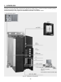
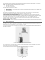
INSTALLATION
If the Thyristor Power Controller is brought into the operations room from a cold environment, moisture can
occur. Prior to it being commissioned, the Thyristor Power Controller must be absolutely dry. For this
reason, wait for a minimum period of two hours before commissioning.
Install the device upright.
3
CONNECTION
Prior to connection, it must be ensured that the voltage information on the type plate corresponds with the
mains voltage.
The electrical connection is carried out at the designated points with the required cross section and the
appropriate screw cross sections.
OPERATION
The Thyristor Power Controller may only be connected to the mains voltage if it has been ensured that any
hazard to people and system, especially in the load section, has been eliminated.
Protect the device from dust and moisture.
Do not block vents.
MAINTENANCE, SERVICE, MALFUNCTIONS
The icons used below are explained in the chapter safety regulations.
CAUTION
Should smoke, smell or fire occur the Power Controller must be disconnected from the mains
immediately.
CAUTION
For maintenance and repair work, the Power Controller must be disconnected from all external voltage
sources and protected against restarting. Make sure to wait minimum 1 minute after switch-off
(discharge time of the attenuation capacitors). The voltage-free state is to be determined by means of
suitable measuring instruments. This work is only to be carried out by a skilled electrician. The
electrical regulations which are locally valid are to be adhered to.
CAUTION
The Thyristor Power Controller contains hazardous voltages. Repairs may generally only be
performed by qualified and trained maintenance personnel.
CAUTION
Hazard of electrical shock. Even after disconnection from the mains voltage, capacitors may still
contain a dangerously high power level.
CAUTION
Hazard of electrical shock. Even when the Thyristor Power Controller is not triggered, the load circuit
is not disconnected from the mains.
ATTENTION
Different components in the power section are screwed in place using exact torques. For safety
reasons, power components repairs must be performed by Pyrocontrole.
4
CONTENTS
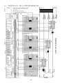
Safety Instructions ..................................................................................................................................................... 3 Safety notes ............................................................................................................................................................... 8 Remarks on the present operating instructions and Thyritop 40 ............................................................................. 10 1 Introduction ...................................................................................................................................................... 12 1.1 General .................................................................................................................................................... 12 1.2 Specific characteristics ............................................................................................................................ 12 1.3 Type designation...................................................................................................................................... 13 2 Functions ......................................................................................................................................................... 14 2.1 Operating modes ..................................................................................................................................... 14 2.2 Set point control characteristic ................................................................................................................. 16 2.3 Control types ............................................................................................................................................ 18 2.3.1 Controlled value ............................................................................................................................... 18 2.4 Indications ................................................................................................................................................ 18 2.4.1 LED indications ................................................................................................................................ 18 2.4.2 Relay indications K1-K2-K3 ............................................................................................................. 19 2.5 Monitoring ................................................................................................................................................ 20 2.5.1 Monitoring of mains voltage ............................................................................................................. 20 2.5.2 Load monitoring ............................................................................................................................... 20 2.5.3 Fast current monitoring ("Short circuit monitoring") ......................................................................... 22 2.5.4 Fan monitoring ................................................................................................................................. 22 3 Operation ......................................................................................................................................................... 23 3.1 Local operating and control unit LBA-2.................................................................................................... 23 3.1.1 Start screen ...................................................................................................................................... 23 3.1.2 Settings LBA-2 ................................................................................................................................. 24 3.1.3 Settings Thyritop 40 ......................................................................................................................... 24 3.1.4 Easy start ......................................................................................................................................... 25 3.1.5 Line chart/ Process data recorder.................................................................................................... 25 3.1.6 Load/Save data ................................................................................................................................ 25 3.1.7 Bluetooth .......................................................................................................................................... 26 3.1.8 Passwords / Authorization ............................................................................................................... 26 3.1.9 Upload new LBA-2 firmware ............................................................................................................ 26 3.1.10 Languages ....................................................................................................................................... 26 3.2 LBA-2 Tool ............................................................................................................................................... 27 3.2.1 Overview .......................................................................................................................................... 27 3.2.2 Languages ....................................................................................................................................... 28 3.2.3 Select log file folder.......................................................................................................................... 28 3.2.4 Calendar navigation ......................................................................................................................... 28 3.2.5 Time axis .......................................................................................................................................... 28 3.2.6 Value axes ....................................................................................................................................... 29 3.2.7 Values dislay .................................................................................................................................... 29 3.2.8 Event reports .................................................................................................................................... 29 3.2.9 PDF export ....................................................................................................................................... 30 3.2.10 Example ........................................................................................................................................... 30 3.3 Cabinet installation kit (SEK) ................................................................................................................... 30 3.4 Thyritop-Tool Family ................................................................................................................................ 30 3.5 Erro acknowledgement / data logger ....................................................................................................... 32 3.5.1 LBA-2 ............................................................................................................................................... 32 3.5.2 THYRITOP-TOOL FAMILY .............................................................................................................. 32 3.6 LBA-2 menu structure .............................................................................................................................. 34 4 External connection ......................................................................................................................................... 39 4.1 Power supply for Thyritop 40 ................................................................................................................... 39 4.2 Power supply for the control device A70 ................................................................................................. 39 4.3 Power supply for the ventilator ................................................................................................................ 40 4.4 Reset ........................................................................................................................................................ 40 4.5 Controller inhibit ....................................................................................................................................... 40 4.6 Quit........................................................................................................................................................... 40 4.7 Set point inputs ........................................................................................................................................ 41 4.8 ASM input ................................................................................................................................................ 41 4.9 dASM input - dASM output ...................................................................................................................... 41 5
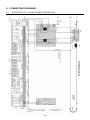
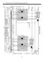
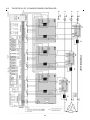
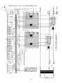
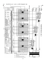
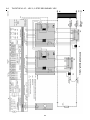
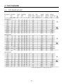
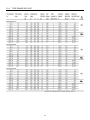
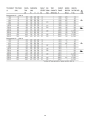
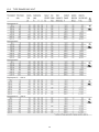
4.10 4.11 4.12 4.13 4.14 4.15 Analog outputs ......................................................................................................................................... 41 Current transformer.................................................................................................................................. 41 Voltage transformer ................................................................................................................................. 43 Other connections and terminal strips ..................................................................................................... 45 Synchronization ....................................................................................................................................... 46 Component mounting diagram control device ......................................................................................... 47 5 Interfaces ......................................................................................................................................................... 48 5.1 RS232 interface ....................................................................................................................................... 49 5.2 Fiber optic interface ................................................................................................................................. 50 5.2.1 Fiber optic distribution system ......................................................................................................... 50 5.3 Bus interfaces (optionnal) ........................................................................................................................ 51 6 Mains load optimization for operating mode TAKT.......................................................................................... 52 6.1 dASM mains load optimization ................................................................................................................ 52 6.2 Software synchronization ......................................................................................................................... 56 6.3 ASM procedure (patented) ...................................................................................................................... 57 7 Mains load optimization VSC ........................................................................................................................... 58 8 Connecting diagrams ....................................................................................................................................... 60 8.1 Thyritop 40 1P, 1 phase power controller ................................................................................................ 60 8.2 Thyritop 40 2P, 2 phases power controller .............................................................................................. 61 8.3 Thyritop 40 3P, 3 phases power controller .............................................................................................. 62 8.4 Thyritop 40 1P…VSC 2, 2 step primary VSC .......................................................................................... 63 8.5 Thyritop 40 1P…VSC 3, 3 step primary VSC .......................................................................................... 64 8.6 Thyritop 40 1P…VSC 2, 2 step secondary VSC ..................................................................................... 65 8.7 Thyritop 40 1P…VSC 3, 3 step secondary VSC ..................................................................................... 66 9 Special remarks ............................................................................................................................................... 67 9.1 Installation ................................................................................................................................................ 67 9.2 Protection against contact IP20 ............................................................................................................... 67 9.3 Commissioning ........................................................................................................................................ 68 9.4 Service ..................................................................................................................................................... 68 9.5 Checklist .................................................................................................................................................. 69 10 Type overview .................................................................................................................................................. 70 10.1 Type range 400 Volt................................................................................................................................. 70 10.2 Type range 500 Volt................................................................................................................................. 71 10.3 Type range 690 Volt................................................................................................................................. 73 11 Technical data.................................................................................................................................................. 74 12 Dimensional drawings ...................................................................................................................................... 77 13 Approvals and conformities ............................................................................................................................. 89 TABLES INDEX
Tab. 1 : Behavior in case of load change ...................................................................................................................18 Tab. 2 : Partial load breakdown with heating elements switched in parallel, undercurrent, relative monitoring ........ 21 Tab. 3 : Partial short-circuit with heating elements switched in series, overcurrent, relative monitoring ...................21 Tab. 4 : Overview monitoring ......................................................................................................................................22 Tab. 5 : Error and data logger messages ...................................................................................................................33 Tab. 6 : LBA-2 menu structure....................................................................................................................................38 Tab. 7 : Terminal strip X1 ...........................................................................................................................................39 Tab. 8 : Reset .............................................................................................................................................................40 Tab. 9 : Controller lock ................................................................................................................................................40 Tab. 10 : Quit ..............................................................................................................................................................40 Tab. 11 : Current transformer .....................................................................................................................................42 Tab. 12 : Voltage transformer .....................................................................................................................................43 Tab. 13 : Voltage measurement jumpers ...................................................................................................................43 Tab. 14 : Terminal strip X2 for K1, K2, K3 ..................................................................................................................45 Tab. 15 : Terminal strip X5 in the control device ........................................................................................................45 Tab. 16 : Terminal strip X6 .........................................................................................................................................45 Tab. 17 : Terminal strip X7 .........................................................................................................................................46 Tab. 18 : Synchronization jumpers .............................................................................................................................46 Tab. 19 : Fiber optic distances....................................................................................................................................50 6
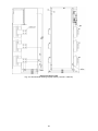
ILLUSTRATIONS INDEX
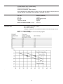
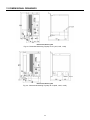
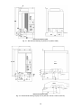
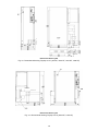
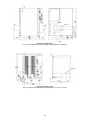
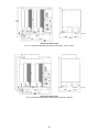
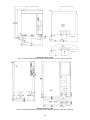
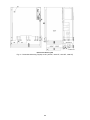
Fig. 1 : Control characteristic for U control .................................................................................................................16 Fig. 2 : Total setpoint calculation ................................................................................................................................17 Fig. 3 : Switch-on fault bridging ..................................................................................................................................19 Fig. 4 : Absolute value monitoring ..............................................................................................................................20 Fig. 5 : Relative monitoring .........................................................................................................................................20 Fig. 6 : Start screen LBA-2 .........................................................................................................................................23 Fig. 7 : Main menu LBA-2 (sample) ............................................................................................................................24 Fig. 8 : Example entries log files .................................................................................................................................25 Fig. 9 : Access levels ..................................................................................................................................................26 Fig. 10 : Language selection.......................................................................................................................................28 Fig. 11 : Folder selection ............................................................................................................................................28 Fig. 12 : Calendar navigation ......................................................................................................................................28 Fig. 13 : Calendar navigation with no log files found ..................................................................................................28 Fig. 14 : Standard zoom keys .....................................................................................................................................28 Fig. 15 : Y scaling panel .............................................................................................................................................29 Fig. 16 : Value panel ...................................................................................................................................................29 Fig. 17 : Event Panel details .......................................................................................................................................29 Fig. 18 : Example calendar .........................................................................................................................................30 Fig. 19 : Example for user interface Thyritop-tool.......................................................................................................31 Fig. 20 : Component mounting diagram control device ..............................................................................................47 Fig. 21 : Interfaces of Thyritop 40 ...............................................................................................................................48 Fig. 22 : Connection of PC to Thyritop 40 via RS232 .................................................................................................49 Fig. 23 : X10 Allocation ...............................................................................................................................................49 Fig. 24 : Signal converter RS232/Fiber optic ..............................................................................................................50 Fig. 25 : Schematic diagram fiber optic Thyritop 40 with LL.V and PC ......................................................................51 Fig. 26 : Wiring of the dASM signal cables .................................................................................................................53 Fig. 27 : LEDs on the RJ45 connectors ......................................................................................................................53 Fig. 28 : ASM wiring ....................................................................................................................................................57 Fig. 29 : Dimensional drawing Thyritop 40 1P (37H, 75H, 110H) ..............................................................................77 Fig. 30 : Dimensional drawing Thyritop 40 1P (80H, 130H, 170H) ............................................................................77 Fig. 31 : Dimensional drawing Thyritop 40 1P (200H, 280H) .....................................................................................78 Fig. 32 : Dimensional drawing Thyritop 40 1P (300 HF, 495 HF, 500 HF, 650 HF) ...................................................78 Fig. 33 : Dimensional drawing Thyritop 40 1P (780 HF, 1000 HF, 1400 HF, 1500 HF) .............................................79 Fig. 34 : Dimensional drawing Thyritop 40 1P (2000 HF, 2100 HF) ...........................................................................79 Fig. 35 : Dimensional drawing Thyritop 40 1P (2600 HF, 2900 HF) ...........................................................................80 Fig. 36 : Dimensional drawing Thyritop 40 2P (37 H, 75 H, 110 H) ...........................................................................80 Fig. 37 : Dimensional drawing Thyritop 40 2P (80 H, 130 H, 170 H) .........................................................................81 Fig. 38 : Dimensional drawing Thyritop 40 2P (200 HF, 280 HF) ...............................................................................81 Fig. 39 : Dimensional drawing Thyritop 40 2P (300 HF, 495 HF, 500 HF, 650 HF) ...................................................82 Fig. 40 : Dimensional drawing Thyritop 40 2P (780 HF, 1000 HF, 1400 HF, 1500 HF) .............................................82 Fig. 41 : Dimensional drawing Thyritop 40 2P (1850 HF, 2000 HF) ...........................................................................83 Fig. 42 : Dimensional drawing Thyritop 40 2P (2400 HF, 2750 HF) ...........................................................................83 Fig. 43 : Dimensional drawing Thyritop 40 3P (37 H, 75 H, 110H) ............................................................................84 Fig. 44 : Dimensional drawing Thyritop 40 3P (80 H, 130 H, 170 H) .........................................................................84 Fig. 45 : Dimensional drawing Thyritop 40 3P (200 HF, 280 HF) ...............................................................................85 Fig. 46 : Dimensional drawing Thyritop 40 3P (300 HF, 495 HF, 500 HF, 650 HF) ...................................................85 Fig. 47 : Dimensional drawing Thyritop 40 3P (780 HF, 1000 HF, 1400 HF, 1500 HF) .............................................86 Fig. 48 : Dimensional drawing Thyritop 40 3P (1700 HF, 1850 HF) ...........................................................................87 Fig. 49 : Dimensional drawing Thyritop 40 3P (2200 HF, 2600 HF) ...........................................................................88 7
SAFETY NOTES
IMPORTANT INSTRUCTIONS AND EXPLANATIONS
Operation and maintenance according to regulation as well as observance of the listed safety regulations is
required for protection of the staff and to preserve readiness to operate. Personnel installing/uninstalling the
devices, commissioning them, operating them, maintaining them must know and observe these safety regulations.
All work may only be performed by specialist personnel trained for this purpose using the tools, devices, test
instruments and consumables provided for this purpose and in good shape.
In the present operating instructions, important instructions are marked using the terms „CAUTION“, „ATTENTION“
and „REMARK“ as well as using the icons explained below.
CAUTION
This instruction shows work and operating procedures to be observed exactly to exclude hazards for
persons.
ATTENTION
This instruction refers to work and operating procedures to be observed exactly to avoid damage or
destruction of Thyritop 40 or parts thereof.
REMARK
This is where remarks about technical requirements and additional information is given, which the user
has to observe.
ACCIDENT PREVENTION RULES
The accident prevention rules of the application country and the generally applicable safety regulations must be
observed in any case.
CAUTION
Before starting any work on Thyritop 40, the following safety regulations must be observed:
switch voltage-free,
secure against switching on,
determine if it is voltage-free,
ground and short-circuit it,
cover or block neighboring parts under voltage.
QUALIFIED PERSONNEL
Thyritop 40 may only be transported, installed, connected, commissioned, maintained and operated by specialists
in command of the respective applicable safety and installation regulations. All work must be monitored by the
responsible specialist personnel. The specialist personnel must be authorized for the work required by the person
responsible for the safety of the system.
Specialists are persons who
have received training and have experience in the respective field of work,
know the respective applicable standards, regulations, terms and accident prevention rules,
have been familiarized with the function and operating conditions of Thyritop 40,
are able to detect and avoid hazards.
WORK OBSERVING SAFETY REGULATIONS
Before removing safety installations for performance of maintenance and repair work or other work, measures due
to operation must be initiated.
Work observing safety regulations also means to point out faulty behavior to colleagues and to notify the office or
person responsible about defects detected.
INTENDED USE
CAUTION
The Thyristor Power Controller may only be employed in the sense of its purpose of use (see the
section of the chapter safety instructions under the same name), otherwise hazards for persons (for
instance electrical shock, burns) and systems (for instance overload) may occur.
8
Any unauthorized reconstruction and modification of Thyritop 40, use of spare and exchange parts not approved by
Pyrocontrole as well as any other use of Thyritop 40 is not allowed. The person responsible for the system must
ensure that
hints on safety and operating instructions are available and observed,
operation conditions and specifications are observed,
protective installations are used,
required maintenance work is performed,
maintenance personnel are immediately notified or Thyritop 40 is immediately put out of commission if
abnormal voltages or noises, higher temperatures, vibrations or similar occur to determine the causes.
These operating instructions contain all information required by specialists for use of Thyritop 40. Additional
information and hints for unqualified persons and for use of Thyritop 40 outside of industrial installations are not
contained in these operating instructions.
The warranty obligation of the manufacturer applies only if these operating instructions are observed.
LIABILITY
In case of use of Thyritop 40 for applications not provided for by the manufacturer, no liability is assumed. The
responsibility for required measures to avoid hazards to persons and property is borne by the operator respectively
the user. In case of complaints, please immediately notify us stating:
type name,
production number,
objection,
duration of use,
ambient conditions,
operating mode.
GUIDELINES
The devices of the type range Thyritop 40 conform to the currently applicable EN 50178 and EN 60146-1-1.
The CE mark on the device confirms observation of the general EG guidelines for 2006/95/EC
(LVD) – low voltage and for 2004/108/EC (EMC) – electromagnet compatibility, if the instructions on installation
and commissioning described in the operating instructions are observed.
Regulations and definitions for qualified personnel are contained in DIN 57105/VDE 0105 Part 1.
Safe isolation to VDE 0160 (EN 50178 Chapter 3)
9
REMARKS ON THE PRESENT OPERATING INSTRUCTIONS AND THYRITOP
40
VALIDITY
These operating instructions refer to latest technical specification of Thyritop 40 at the time of publication and are
for information purposes only. Every effort has been taken to ensure the accuracy of this specification, however, in
order to maintain our technological lead and for product enhancement, we are continually improving our products
which could, without notice, result in amendments or omissions to this specification. Pyrocontrole cannot accept
responsibility for damage, injury, loss or expenses resulting therefrom.
HANDLING
These operating instructions for Thyritop 40 are organized so that all work required for commissioning,
maintenance and repair may be performed by corresponding specialist personnel.
If hazards to personnel and property cannot be excluded for certain work, then this work is marked using certain
icons. The meaning of these icons may be found in the prior chapter safety regulations.
ABBREVIATIONS
In this description, the following specific abbreviations are used:
dASM
ASM
LBA-2
LBA
SEK
LL
LLS
LLE
LLV.V
LLV.4
MOSI
SP
SYT
=
=
=
=
=
=
=
=
=
=
=
=
=
digital mains load optimization, dynamic
automatic synchronization in multiple power controller applications (not for new installations)
Local operating and display unit with touch display
Local operating and display unit (not for new installations)
cabinet installation kit
fiber optic
fiber optic transmitter
fiber optic receiver
fiber optic distribution supply
fiber optic distribution, 4-fold
heating system for molybdenum silicide
set point
synchronized clock
WARRANTY
Customer shall provide written particulars, enclosing the delivery note, within 8 working days to Pyrocontrole on
becoming aware of any defects in the goods during the Warranty period and shall use its best endeavors to provide
Pyrocontrole with all necessary access, facilities and information to enable Pyrocontrole to ascertain or verify the
nature and cause of the defect and carry out its warranty obligations.
If goods are found not to be defective or if any defect is attributable to Customer’s design or material in operation of
the goods, Pyrocontrole will levy a testing charge and where relevant will return the goods to Customer at
Customer’s expense, and shall be entitled to payment in advance of the whole testing and transport charge before
such return.
Pyrocontrole accepts no liability for defects caused by the Customer’s design or installation of the goods; or if the
goods have been modified or repaired otherwise than as authorized in writing by Pyrocontrole; or if the defect
arises because of the fitting of the goods to unsuitable equipment.
Pyrocontrole will cancel all possible obligations incurred by Pyrocontrole and its dealers, such as warranty
commitments, service agreements, etc., without prior notice if other than original Pyrocontrole spare parts or spare
parts purchased from Pyrocontrole are used for maintenance or repair.
10
CONTACT
TECHNICAL QUERIES
If you have any technical queries regarding the subjects dealt with in these operating instructions, please get in
touch with our team for power controllers:
Tel. +33(0)4 72 14 15 40
[email protected]
COMMERCIAL QUERIES
If you have any commercial queries on power controllers, please get in touch with:
Tel. +33(0)4 72 14 15 40
[email protected]
SERVICE HOTLINE
Our team is at your service on the following hotline:
+33(0)4 72 14 15 52
[email protected]
ADDRESS
Pyrocontrole
6bis av. Du Dr. Schweitzer
69881 MEYZIEU CEDEX
FRANCE
Tel. +33(0)4 72 14 15 40
INTERNET
Further information on our company or our products can be found on the internet under
www.pyro-controle.com
COPYRIGHT
Passing on, duplication and/or takeover of these operating instructions using electronic or mechanical means, even
in excerpts, is subject to express prior written approval of Pyrocontrole.
Copyright Pyrocontrole. All rights reserved.
COPYRIGHT NOTICE
Thyritop 40 is an internationally registered trademark of Pyrocontrole.
Windows and Windows NT are registered trademarks of Microsoft Corporation.
All other company and product names are (registered) trademarks of their respective owners
11
1 INTRODUCTION
For transport, assembly, installation, commissioning, operation and decommissioning, the safety instructions
contained in these operating instructions must be applied in any case and made available to all persons handling
this product.
CAUTION
It is important that preset parameters are not adjusted in any way that may cause the Power Controller
to overload. In case of uncertainties or missing information, please contact your supplier.
1.1
GENERAL
Thyritop 40 is a communication enabled SCR thyristor power controller. Below, it is also referred to simply as
power controller. The Thyritop 40 power controller can be installed everywhere where voltages, currents or power
have to be controlled precisely in 1- or 3-phase networks. Several modes of operation and control, good coupling
ability to process and automation technology, high control precision by application of a 32 bit processor and simple
handling ensure that Thyritop 40 is also suitable for new applications.
Thyritop 40 offers new ways for mains load optimization:
In operating mode TAKT, the standard digital mains load optimization of dASM ensures that multiple power
controller applications can be used in an optimal way for the network so that system perturbations are
mainly avoided.
For applications which have to use phase angle firing due to required high dynamic, Thyritop 40...VSC
offers to minimize significantly harmonics by its VSC technology.
Thyritop 40 is suitable in particular for
direct supply of ohmic loads
for loads with large Rhot/Rcold ratio
as primary power controller for a transformer with subsequent load
Due to use of high quality thyristors, the Thyristor Power Controller Thyritop 40 has a type range up to 2900A, the
nominal design loads reach up to about 2860kW.
1.2
SPECIFIC CHARACTERISTICS
Thyritop 40 is characterized by a multitude of specific characteristics, for instance:
easy handling
menu-driven user interface (options: LBA-2 with touch display, Thyritop-Tool Family)
type range 230-690 Volts, 5-2900A, single, double, triple phase
broadband power supply AC 200-500V, 45-65Hz
ohmic load and transformer load
as well as load with large Rhot/Rcold for 1P and 3P
soft start function for transformer load
load circuit monitoring
automatical rotating field recognition for 2P and 3P
U, U2, I, I2, P control as well as without control
operating modes TAKT, VAR, VSC_VAR, SSSD, MOSI (optional sub operating mode of TAKT and VAR)
mains load optimization dASM for applications with multiple power controllers in operating mode TAKT
control of analog set points or via interfaces
fiber optic and RS232 interfaces as standard
electrical separation according to EN 50178 chap. 3
Measured values are given at analog outputs
4 set point channels incl. motor potentiometer to set parameters
The specific characteristics especially include the following options:
LBA-2 local touch display with integrated process data recorder of up to 6 channels
LBA-2 is downward compatible with LBA and can replace it.
Cabinet installation kit (SEK) for LBA-2 with touch display. The SEK allows the installation of LBA-2 in
cabinet doors. It comes with wiring and installation frame.
Bus connection via bus adaptor cards to plug into the Thyritop 40 Power Controller, coupling to different
bus systems, for instance Profibus, other bus systems upon enquiry.
The PC-Software Thyritop-Tool Family for effective commissioning and simple visualization tasks.
Functions are for instance loading, storing, modification, comparing and printing of parameters, set points
and actual value processing, line diagrams of process data (including printing and storing option), bar
12
diagrams, simultaneous display of process data from different power controllers, simultaneous connection
of up to 998 Thyritop 40 Power Controllers.
Patented ASM procedure for dynamic mains load optimization. The ASM procedure (automated
synchronization of multiple power controller applications) is used for dynamic mains load optimization. It
reacts to changes in load and set point, minimizes mains load peaks and associated mains feedback.
Minimizing of mains load peaks means cost savings in operating and investment cost.
For new systems it is recommended to use the high performance dASM instead of ASM.
NOTE:
After purchasing Thyritop-Tool Family software updates (if available) can be downloaded for free from
our homepage.
1.3
TYPE DESIGNATION
The type designation of the thyristor power controllers are derived from the construction of its power section:
TYPE RANGE DESIGNATION
Thyritop 40
1P
FEATURES
1-phase power section,
for single phase operation
2P
2-phase power section
3-phase loads in three phase economic circuit
(not for phase-angle firing VAR)
3P
3-phase power section,
for three phase operation
.P400
Type voltage 230-400 Volt, 45-65 Hz
.P500
Type voltage 500 Volt, 45-65 Hz
.P690
Type voltage 690 Volt, 45-65 Hz
.P ...-0037
Type current 37A (Typecurrent range 5A-2900 A)
.. ...-.... .H
Integrated semi-conductor fuse (all Thyritop 40)
.. ...-.... . F
Forced air cooling with integrated ventilators
The complete type range can be found in the TYPE OVERVIEW in chapter 10
13
2 FUNCTIONS
For optimum adjustment to different products and production processes as well as differently electrical loads,
the most favorable operating and control modes may be set according to the following overview.
2.1
OPERATING MODES
This chapter gives an overview of the different operating modes.
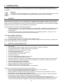
FULL WAVE SWITCH (TAKT)
Depending on the prescribed set point,
the mains voltage is periodically
switched. In this operating mode,
almost no harmonics are created.
Whole multiples of the mains periods
are switched. The operating mode „full
wave switch“ is especially suited for
loads with thermal inertia. For mains
load optimization the standard feature dASM or the optional ASM feature (not for new installations) can be
used with this operating mode.
For operating mode TAKT, also SSSD ramp can be used. This is useful in case of switching on a transformer.
The SSSD ramp will only be used once after reset or impulse inhibit.
Key parameters are
TAKT cycle period T0 [sec]
Soft-Start SST
[msec]
Soft-Down SDN
[msec]
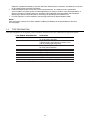
PHASE-ANGLE FIRING (VAR, WITH 1P AND 3P)
Depending on the prescribed set point, the sine oscillation of the mains voltage is gated using a larger or
smaller control angle a. This operating mode is characterized by high control dynamics.
In operating mode phase-angle firing, it is possible to compensate harmonics of the mains voltage by using
circuit variants (e.g. vector group transformer).
To prevent sudden changes of modulation, SSSD feature can be used. It works as a restrictor for peaks.
Key parameters are
Soft-Start SST
Soft-Down SDN
[msec]
[msec]
14
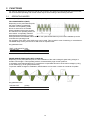
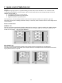
SOFT-START-SOFT-DOWN (SSSD)
The operating mode SSSD operated similar to operating mode TAKT. However, it can be used especially
advantageous in operation of large single loads to reduce pulse-shaped mains loads and therefore to reduce
voltage variations. Switching on and off of turn on-time Ts occurs by applying periods with phase-angle firing
(VAR). Please see following diagram.
Key parameters are
TAKT cycle period T0 [sec]
Soft-Start SST
[msec]
Soft-Down SDN
[msec]
MOSI operation for 1P and 3P
MOSI is a sub-operating mode of the operating modes TAKT and VAR for sensitive heating materials with a
high Rhot/Rcold ratio, for instance molybdenum silicide. The Power Controller always starts with phase-angle
maximum value and actual value to avoid high current amplitudes during the heating-up phase and then
automatically switches to the set operating mode.
For the sub-operating mode MOSI, the key parameters are:
MOSI
Rate of angular displacement 1
Rate of angular displacement 2
Peak current
I max
RAMP/ STELL
[°el/s]
[°el/s]
[A]
[A]
MAINS LOAD OPTIMIZATION (WITH DASM OR OPTIONAL ASM PROCESS)
For systems in which several power controllers are employed in full wave switch mode TAKT, it is possible that
individual power controllers are synchronized so that a regular mains load is achieved by defined switching of
the individual power controller. This avoids load peaks by random simultaneous switching of many power
controllers and load troughs are filled up. The upstream transformer and/or the upstream feed point may be
designed for a lower load. Besides savings in investment and operating costs it also results in considerable
lower system perturbations.
For new installations the dASM process is recommended due to its quicker and easier handling (see chapter
6.1).
15
2.2
SET POINT CONTROL CHARACTERISTIC
The set point control characteristic of Thyritop 40 may be easily adapted for the control output signal of the
upstream process controller or automation system. All signals customary on the market may be used. The
adaption is made by changing the starting and ending points of the control characteristic. Inverted operation
(ending value is smaller than the starting value in voltage or current) is also possible.
The effective set point is the total set point. It is formed by adding the four set points as shown in fig. 2.
In the simplest case all the set point values are added algebraically. The prerequisite for a set point to influence
the total set point value is that it must be enabled by the set point Enable Register.
Set point 1 (X5.2.10 - X5.1.13 ground) 0-20mA default
Set point 2 (X5.2.11 - X5.1.13 ground) 0-5V default
The inputs set point 1, 2 are two electrically equal analogue inputs for current or voltage signals, with
subsequent A/D converter (resolution 0.025% of the final value), and they may be set to the following signal
ranges:
0(4)-20 mA
0-5 V
0-10 V
(Ri = ca. 250 V / max. 24mA)
(Ri = ca. 8,8 kV / max. 12V)
(Ri = ca. 5 kV / max. 12V)
see ATTENTION
The following table shall be used for the hardware configuration of the set point inputs (see also FILE
COMPONENT MOUNTING DIAGRAM CONTROL DEVICE, figure 10). If the hardware configuration is
changed, the Thyritop 40 parameters must be changed accordingly with the LBA-2 or the Thyritop-Tool Family.
X221 for Set point input 1
JUMPER X221
closed*
open
Signal range
0(4) -20mA
0-5V / 0-10V
Set point input 1
(X5.2.10)
(X5.2.10)
X222 for Set point input 2
JUMPER X222
Closed
Open *
Signal range
0(4) -20mA
0-5V / 0-10V
Set point input 1
(X5.2.11)
(X5.2.11)
* default
For a set point poti (e.g. 5-10 kV) 5V supply voltage can be taken from terminal X5.2.5 (Ri = 220V, short-circuitproof).
ATTENTION
If the open-circuit voltage of the connected set point exceeds 12V in the 20mA signal range, the set
point inputs can be destroyed, if the belonging JUMPER (X221, X222) is open.
Within the stated input ranges, these values with the control characteristic may be adjusted to any
common signal characteristic.
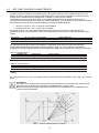
Fig. 1 : Control characteristic for U control
16
Set point 3: Set point of the PLC system or PC via RS232 or fiber optic connection (standard) X30, X31 or
via the optional bus interface.
Set point 4: Set point input (motor potentiometer function) settings as for set point 3 but additionally via
LBA-2. Set point 4 is stored in case of mains failure.
SET POINT CONTROL CHARACTERISTICS
The set point control characteristic (Fig. 1) of Thyritop 40 may be easily adapted for the control output signal of the
upstream process controller or automation system. All signals customary on the market may be used.
The adaption is made by changing the starting and ending points of the control characteristic. Inverted operation
(ending value is smaller than the starting value in voltage or current) is also possible.
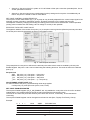
EFFECTIVE TOTAL SET POINT VALUE
The algebraic addition of the results of set point (1,2) to set point 3 and 4 gives the (effective) total set point value
for the set point control characteristic as shown in the following figure.
Fig. 2 : Total setpoint calculation
The prerequisite for a set point to influence the total set point value is that it must be enabled by the set point
Enable Register. Set point 1 and 2 can be linked using the following functions. The result of this link is called set
point (1,2).
Set point link
ADD
IADD
_Pro
_IPro
Set point (1,2) = Set point 1 + Set point 2
Set point (1,2) = Set point 1 - Set point 2
Set point (1,2) = Set point 1 * Set point 2
Set point (1,2) = Set point 1 * (1 - Set point 2)
VALUE RANGE OF SET POINT (1,2)
For the link result of set point (1,2) the following value range applies:
0 ≤ Set point (1,2) ≤ Set point max (Umax, Imax, Pmax).
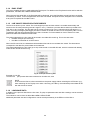
SET POINT ENABLE REGISTER
The set point Enable Register (AD_P_SW_ENABLE, adr. 94) enables the 4 set points to be shut off or enabled
independently. Only enabled set point inputs are part of the effective total set point value.
The shut off or inactive set points are shown by the LBA-2 and can thus, if necessary, be checked before
connecting.
The set point Enable Register can be changed from all service units (Bus, Thyritop-Tool Family, LBA-2).
Example:
8
1
1
0
0
0
4
1
0
1
0
0
2
1
0
0
1
0
1
1
0
0
1
0
Value
15
8
4
3
0
ABBR.
STD
LOC
REMOTE
ANA
EXPLANATION
Standard (all ON)
Motor potentiometer set point 4 (LOCAL)
Bus set point 3
Analog-set points 1,2
All set points inactive
17
2.3
CONTROL TYPES
Thyritop 40 has five control types effective as underlying controls. Mains voltage variations and load changes are
directly and therefore quickly adjusted by bypassing of the slow temperature control system.
Before commissioning of the power controller and selection of a control type, you should be familiar with the
operating procedure respectively the effect for application (further see TAB. 1: BEHAVIOR IN CASE OF LOAD
CHANGE in the following chapter).
2.3.1 CONTROLLED VALUE
The controlled value effective on the load is proportionate to the total set point, depending on the control type:
CONTROL TYPE
P control
U control
U² control
I control
I² control
No control
CONTROL VALUE (PROPORTIONATE TO THE TOTAL SET POINT)
output (active) power, P
output voltage, Urms
output voltage, U²rms
output current, Irms
output current, I²rms
Depending on operating mode :
TAKT : TS/T0 ratio (full scale 1)
VAR : alpha (full scale 180°el)
LIMITING OF SIGNALS
Independent of the control type set, additionally minimum and maximum limiting values may be set. For this
purpose, also refer to Fig. 1 control characteristic.
The maximum limiting values determine the maximum modulation of the load.
The minimum limiting values should ensure minimum modulation via the control angle (for instance minimum
heating of the load).
CONTROLLER RESPONSE
If the load resistance changes, for instance due to temperature effect, ageing or load fault, then the values
(depending on control type) effective on the load change as follows:
CONTROL MODE
U
U²
I
I²
P
LOAD RESISTANCE GETS
SMALLER
P
ULoad
ILoad
↗
↗
=
↗
↗
=
↘
↘
=
↘
↘
=
↘
↗
=
No control
↗
=
LOAD RESISTANCE GETS
LARGER
P
ULoad
ILoad
↘
↘
=
↘
↘
=
↗
↗
=
↗
↗
=
↗
↘
=
↗
↘
=
↘
General modulation limits
Effective limitations *
Irms max, Pmax
Urms max, Pmax
Urms max, Irms max
Urms max, Irms max,
Pmax
Ts=Ts max
α=α max
* If one of the limits is exceeded, then the signaling relay K2 and the LED Limit react
(Default values of parameter settings).
Tab. 1 : Behavior in case of load change
2.4
INDICATIONS
2.4.1 LED INDICATIONS
The LEDs on the front side signal the following states:
ON
green: operating indication, power supply controller board
red: RESET active
CONTROL
modulation percentage indication, flashing*
LIMIT
limitation is active, relay K2 switches*
PULSE LOCK
Controller Lock active, but load control is continued at pulse limits
(default value = 0)*
FAULT
fault present*
OVERHEAT
overheating of power section
(in case of ..HF types, check ventilator)*
* Default setting
18
Activation of the integrated semiconductor fuse may be signaled using the fault indicating relay K1 rest current,
contactor, otherwise separate supply of the control device required). In case of power controllers from model
current 495A, additional signaling is performed via an indicator at the semiconductor fuse.
2.4.2 RELAY INDICATIONS K1-K2-K3
The Thyritop 40 power controller is fitted with three relays. Each of these relays has a change over contact, in
principle a value has been allocated in the event register. The default values for parameter settings are listed in
chapter 3.5 ERROR ACKNOWLEDGEMENT / DATA LOGGER.
The connection terminals are specified in chapter 4 EXTERNAL CONNECTIONS.
ALARM RELAY K1
The relay K1 is activated if a fault is detected in the system. The effective direction, whether it should close or open
in case of fault, may be set using the parameter Relay ON at message or Relay OFF at message by using LBA-2
or Thyritop-Tool Family. Which indications lead to switching of the relay may also be set.
Recommendation: keep the default setting.
LIMITING RELAY K2
The relay K2 only closes (in default setting) if at least one of the following values is exceeded:
1. max. admissible effective value of the load current
2. max. admissible effective value of the load voltage
3. max. admissible active power of the load
The relay releases if none of the values is exceeded anymore. It is possible to set which indications lead to
switching of the relay. Recommendation: keep the default setting.
OPTIONAL RELAY K3
If changes are made to the default relay settings due to the application, then preferably the relay K3 should be reparameterized.
It is possible to realize functions like for instance a follow-up relay for ventilator control or bypass the alarm relay at
startup of the system. It may also be used as a further alarm relay or limiting relay, by re-parameterization.
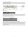
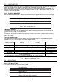
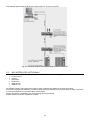
The illustration shows the relay K3 for bridging the startup alarm.
Fig. 3 : Switch-on fault bridging
19
2.5
MONITORING
Faults occurring in the power controller or in the load circuit are signaled (s. error messages of LBA-2). Signaling is
performed via LED Fault and via relay with potential-free change-over contact.
The fault buffer may be read via LBA-2 or the interface after selecting the status line. Simultaneously with the fault
signal, the pulse shutdown may optionally also be set (Pulse inhibit On / Off).
The number and content of occurred warnings or errors are shown in the status line of LBA-2 touch display. By
selecting the status line, the message can be retrieved.
2.5.1 MONITORING OF MAINS VOLTAGE
The power controller is equipped with mains voltage monitoring. The limits may be set for U mains min and U
mains max. If limits are reached, a status message will be generated.
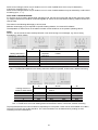
2.5.2 LOAD MONITORING
It is possible to monitor load by absolute monitoring of heating elements with Rhot/Rcold ≈ 1 and relative
monitoring of heating elements with Rhot/Rcold ≠ 1.
2.5.2.1 Absolute value monitoring current
This function allows monitoring of a freely selectable absolute current limit. The parameters for the value may be
set in ampere.
Fig. 4 : Absolute value monitoring
This absolute value monitoring lends itself to one or more load resistances organized in parallel or in series.
Generally, the effective current value measured is continuously compared with a presettable absolute current limit
for undercurrent or overcurrent. If these limits are undercut or exceeded an indication occurs after Tv =10 mains
periods. In case of resistor elements organized in parallel, it is therefore possible, using the lower current limit, to
detect a partial load interruption. Using the upper current limit, in case of resistors switched in series, shortcircuiting of an element may be detected.
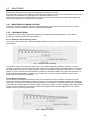
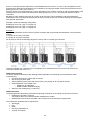
2.5.2.2 Relative monitoring
This monitoring is sensible if the resistance value of the load slowly changes. Changes in resistance may for
instance be caused by temperature changes or by ageing. The current (b) of the Power Controller is regarded as
100% load current (current in fault-free state) after activation of the RESET or CONTROLLER LOCK. The RESET
is automatically activated after each startup, restart or after mains outage. In case of relatively slow changes of the
current, due to characteristics of the above mentioned heating elements, automatic adjustment of the internal
reference value to 100% is performed (b‘).
Fig. 5 : Relative monitoring
20
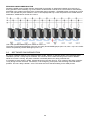
Quick current changes, which may for instance occur in case of partial short-circuit, may be detected by
overcurrent monitoring (max., a – a‘).
Quick current changes, which may for instance occur in case of load breakdown may be detected by undercurrent
monitoring (min., c – c‘).
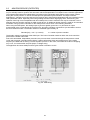
NOTE FOR LOAD MONITORING:
If a Thyritop 40 3P is used in phase-angle operating mode, the star point of the load and the star point of the (builtin) voltage transformers should be connected together to ensure an accurate load monitoring. Please contact us in
case of need.
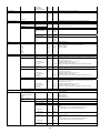
The values in the following table apply to ohmic loads.
Different values apply may be required for specific heating resistors, for instance IR radiators.
The adjustable % values shown in the tables are load current variations on the present operating values.
NOTE
Values < 10% should be chosen carefully because it can cause wrong error messages, e.g. due to strong
fluctuations in mains voltage.
1P
2P*/3P
3P
Star with
Star without
delta
Star with neutral
Heating elements in
separate
neutral
parallel for each strand
starpoints
5
10%
10%
8%
6%
10%
4
13%
13%
10%
7%
13%
3
17%
17%
13%
10%
17%
2
25%
25%
20%
12%
25%
1
50%
50%
50%
21%
50%
* For Thyritop 40 2P: additional external converters in phase L2 are possible.
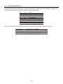
Tab. 2 : Partial load breakdown with heating elements switched in parallel, undercurrent, relative monitoring
1P
2P*/3P
3P
Heating elements in
Star without
delta
Star with neutral
series for each strand
neutral
6
10%
7%
6%
10%
5
13%
8%
7%
13%
4
17%
10%
9%
17%
3
25%
14%
13%
25%
2
50%
25%
26%
50%
* For Thyritop 40 2P: additional external converters in phase L2 are possible.
Tab. 3 : Partial short-circuit with heating elements switched in series, overcurrent, relative monitoring
Thyritop 40 determines the load conductance separately for each phase. These values are available from LBA-2,
Thyritop-Tool Family and the Bus interface. The current resistance can be determined by reading out and
converting from the conductance.
21
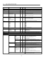
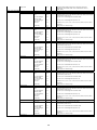
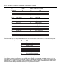
2.5.2.3 Overview monitoring
The following table offers an overview of the possible monitoring functions of the thyristor power controller Thyritop
40.
TYPE OF MONITORING
Unet max
mains overvoltage
Unet min
mains undervoltage
Iload max-REL
overcurrent relative
Iload max-ABS
overcurrent absolute
PARAMETER SETTINGS
input in volts
input in volts
0-100%
Re: measured load current
after each RESET/control lock
input in ampere
DEFAULT / REMARKS
Type voltage + 20%
Type voltage - 20%
REL_ABS = REL
UE_S = ON
REL_ABS = ABS
UE_S = ON
Iload min-REL
undercurrent relative
0 to 99%
REL_ABS = REL
Re: measured load current after UN_S = ON
each RESET/control lock
Iload min-ABS
undercurrent absolute
input in ampere
REL_ABS = ABS
UN_S = ON
pulse switch off pulse switch off
ON: pulse switch off after fault indication is always issued
by software
indication
in case of synchronization
OFF: in case of fault
SYT 9, RESET of all Power
Controllers is required
K1 closed-circuit alarm relay K1
ON: relay K1 released in case the alarm relay switches
of fault
upon activation of RESET
OFF: relay K1 pulled-in in case
of fault
Tab. 4 : Overview monitoring
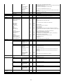
2.5.3 FAST CURRENT MONITORING ("SHORT CIRCUIT MONITORING")
Each mains half-wave, the measured actual value of current (per regulated phase) will be compared to an
adjustable limit. If limits are exceeded, a status message will be generated. The message is:
I²t current limit is exceeded
The message can be analyzed by the following parameters:
Fast current monitoring L1
Fast current monitoring L2
Fast current monitoring L3
[A]
[A]
[A]
The messages can be analyzed via relay, LED, data logger, pulse switch off (quit the message).
2.5.4 FAN MONITORING
The separately ventilated power controllers (-...HF) are fitted with thermal monitoring. The temperature is measured
on the heat sink. In case of a temperature over range, a fault indication is issued:
Unit excess temp.
As a standard the device will be switched off and LED Overheat will be lit.
ATTENTION
When using the device under UL conditions, this feature has to be switched on.
22
3 OPERATION
This chapter presents the operating options of Thyritop 40 using local operating and display unit LBA-2 and
visualization and commissioning software Thyritop-Tool Family.
LBA-2
LBA-2 Tool
SEK
Thyritop-Tool Family
3.1
for Thyritop 40 parameterization and process data
for visualization /analysis of saved process data and messages of LBA-2
for operating of Thyritop 40 with LBA-2 on cabinet doors
for Thyritop 40 parameterization and process visualization
LOCAL OPERATING AND CONTROL UNIT LBA-2
The new local display and control unit LBA-2 can be used as a substitute for its predecessor LBA model and
enables easy operation for Thyritop 40 thyristor power controllers. The LBA-2 is equipped with a graphic touch
display and SD card and is designed to be used either with Bluetooth (model 2.000.000.409) or without Bluetooth
(model 2.000.000.408). For both versions the process data recorder feature is included (see chapter 3.1.5 LINE
CHART)
With the menu based graphic user interface, LBA-2 offers an intuitive operating of Thyritop 40 – if requested,
further information for configuration and parameterization can be seen in the menu structure table.
If LBA-2 is not in use (parameterized) for a longer duration, the display will dim its brightness.
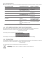
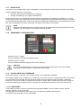
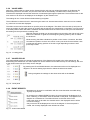
3.1.1 START SCREEN
The start screen of LBA-2 is its central display which is the first to see after starting
LBA-2. It can be switched to:
• Line chart (6 values, optional)
• Operation display (6 values, optional)
• Bar chart (4 values, optional)
• Data logger
The values, which have been selected for the line chart, will be saved as process
data on the SD card by LBA-2. They can be analyzed by the free LBA-2 Tool (see
chapter 3.2 LBA-2 TOOL).
The four buttons on the start screen have the following functions:
Fig. 6 : Start screen LBA-2
The house symbol will return the user to the start screen from any submenu.
The list symbol will take the user to the main menu of the LBA-2 with further menus to parameterize
and to configure
• LBA-2
• Thyritop 40
The OFF button operates as a data backup before shutting down LBA-2.
NOTE
The LBA-2 must be shut down in order to save all settings and data prior to removing the LBA-2 from
the power controller.
By using the logo key, the user can switch between the line chart display, the bar chart display, the
operation display and the data logger.
23
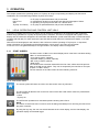
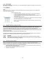
3.1.2 SETTINGS LBA-2
Fig. 7 : Main menu LBA-2 (sample)
To change anything on LBA-2, the button SETTINGS in the main menu has to be pressed. By using the button
LBA-2 the following menus will be available:
Settings for LBA-2
Operation display, bar chart, and line chart settings
Display settings
Startscreen
Languages
Bluetooth
Authorization and passwords
Information about the device
Address
Reset to factory settings
3.1.3 SETTINGS THYRITOP 40
To change anything on Thyritop 40, the button SETTINGS in the main menu has to be pressed.
By using the button Thyritop 40 the following menus will be available:
Settings for Thyritop 40
Operating mode
Control mode
Control parameters
Limits
Analog outputs
Setpoint inputs
Relays / LED / pulse inhibit
Address
Hardware
Monitoring
Temperature
Data logger Thyritop 40
24
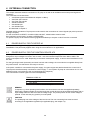
3.1.4 EASY START
This menu enables the user to easily adjust the Thyritop 40. For details on the EasyStart function and its selection
possibilities, see table LBA-2 MENU STRUCTURE.
When the user first starts LBA-2, the EasyStart will be displayed. Once the EasyStart prompt has been conducted
successfully on LBA-2, it will not appear each time LBA-2 is started. Irrespective of this, EasyStart can be selected
at any time if required via the LBA-2 menu.
3.1.5 LINE CHART/ PROCESS DATA RECORDER
The line chart shows up to 6 values. The chronological process of these values is recorded automatically and
saved on the SD card (measuring interval is approx. 1sec.). Therefore a process data recorder is provided to the
user with up to 6 channels. The SD card has an amount of memory for max. 6 channels which lasts approx. 2.7
years. Occurring messages (data logger) will also be saved on the SD card and can be analyzed by LBA-2 Tool in
combination with the saved signal sequence of the 6 channels. For further details on how to set the line chart,
please see table LBA-2 MENU STRUCTURE.
The values selected for the line chart will be saved in the folder SD-Card:\Log. This is the case when
the date changes (at 0.00 hours)
the LBA-2 is switched off via OFF button
When the SD card is full, the oldest data will be deleted first and the current data then saved. The data names
correspond to the date the process data were measured:
The values selected for the line chart (up to six) will be saved on the 4GB SD card, which is included with delivery
under the file named SD-Card:\Log.
Fig. 8 : Example entries log files
Example of LOG file:
131004.LOG (the process data were measured on October 4th, 2013
NOTE
In the event the LBA-2 is disconnected from the power supply without switching the OFF button (e.g.,
when switching off the Thyritop 40 or when “removing „the LBA-2), the measured process data will be
lost and will not be saved.
3.1.6 LOAD/SAVE DATA
In addition to the process data from the line chart, Thyritop 40 parameter sets and LBA-2 settings can be stored on
the SD card.
The submenus can be found in table LBA-2 MENU STRUCTURE.
Additional parameter sets and configurations can be stored permanently in the EEProm of the LBA-2.
25
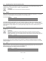
3.1.7 BLUETOOTH
This option is only available with model no P01646945. It can be switched on and off in the submenu of the LBA-2.
It offers a wireless operation of Thyritop 40
Via Thyro-App (by Android smartphone or tablet PC)
Thyritop-Tool Family (e.g. by laptop and Bluetooth)
As soon as the LBA-2 is connected via Bluetooth using the Thyro-App to a Smartphone or Tablet PC, or to a PC
via the Thyritop-Tool Family, the display of the LBA-2 shows a Bluetooth symbol and all other functions of the LBA2 will be automatically deactivated. Therefore operations via display and via Bluetooth are not possible at the same
time. Once the Bluetooth connection has ended, the display of the LBA-2 is active again.
NOTE
When using the Bluetooth feature, all other functions are deactivate except the BLUETOOTH ACTIV
SYMBOL – this also applies to the PROCESS DATA recorder.
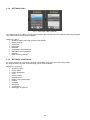
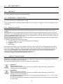
3.1.8 PASSWORDS / AUTHORIZATION
Fig. 9 : Access levels
Password Level 1: 160387
Access to parameter settings or EasyStart function
Password Level 2: 311263
Access to detailed parameter settings of the power controller
CAUTION
To avoid unauthorized access, change your password settings the first time you use the LBA-2.
Only 6-digit numerical password combinations are possible!
3.1.9 UPLOAD NEW LBA-2 FIRMWARE
This function enables, if required, current LBA-2 firmware to be uploaded (if available).
The software update can be copied by PC or Notebook on to the SD card of the corresponding LBA-2. Do not open
up a new folder on the SD card, but copy the file in the SD card’s root directory and if necessary, replace the
existing file. As soon as the SD card is inserted in the LBA-2, and the latter is inserted into the active Thyritop 40,
the firmware update will load automatically. A progress bar will appear that shows the remaining waiting time.
3.1.10 LANGUAGES
In the standard version of LBA-2 are the following languages available: French, English, German, Spanish,
Chinese, Swedish, Czech and Turkish.
The languages can be selected in the LBA-2 menu, see table LBA-2 MENU STRUCTURE.
On request further languages can be implemented.
26
3.2
LBA-2 TOOL
The LBA-2 Tool (free of charge) offers users to store data on the SD card and to analyze the according process
data in combination with data logger entries via PC or Notebook. First the LBA-2 Tool program must be installed on
your PC or Notebook. The LBA-2 Tool can be downloaded from the Pyrocontrole website:
www.pyro-controle.com
All downloaded data have to be copied into a directory. LBA-2 Tool.exe starts up the application.
Then the LOG files, in the folder LOG, can be selected and opened by the LBA-2 Tool. To use the files with LBA-2
Tool, the LOG files can be saved locally on the PC or another medium.
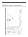
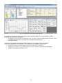
3.2.1 OVERVIEW
27
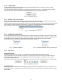
3.2.2 LANGUAGES
In the standard version of LBA-2 are the following languages available: French, English, German, Spanish,
Chinese, Swedish, Czech and Turkish.
The language selected for the application changes the language during runtime. The language selected will be
stored in the user’s Windows profile and will be applied again when the program is restarted.
Fig. 10 : Language selection
3.2.3 SELECT LOG FILE FOLDER
A folder with valid log files can be selected via the folder selection. Once the folder is selected, it will be stored in
the user’s Windows profile and will be applied again when the program is restarted.
Selecting a folder means that the folder will be scanned and all files opened in order to see whether the log files are
valid. If there is no read permission for the folder, no data can be located. Data that cannot be opened will be
ignored. Data that do not have the required log file identification will be ignored.
Fig. 11 : Folder selection
3.2.4 CALENDAR NAVIGATION
If no valid log files can be found in the selected folder, Calendar navigation will display crossed out of date values.
If valid log files are located, the valid date values will be visible. Dates between the first and last valid dates, which
are invalid will also be crossed out. After selecting a new folder, the last valid log date will be selected.
When clicking onto a valid date, a diagram from that day will be illustrated.
Fig. 13 : Calendar navigation with no log files found
Fig. 12 : Calendar navigation
3.2.5 TIME AXIS
STANDARD ZOOM
Once the program has been turned on, each diagram will be displayed with the 24h zoom setting.
This corresponds to the data stored in the log file. By clicking on the other zoom settings, the data view will be
reduced accordingly. With the aid of the displayed scrollbar under the diagram, the data view can be shifted
horizontally along the time axis.
The buttons Back and Next, next to the standard zoom, direct to the previous or following day of a saved LOG file.
Fig. 14 : Standard zoom keys
DETAILED ZOOM
By sliding the mouse horizontally on the diagram, a new X axis view can be selected. Thus you can zoom in to a
one-minute section. The detailed view that is then displayed can be magnified again only after entering a standard
zoom setting.
28
3.2.6 VALUE AXES
With the Y scaling panel, the axes can be changed for the units (up to 6 values) that appear in the diagram. By
deactivating the AUTO checkbox, the part of the axis that is automatically calculated can be set by the user.
Therefore the displayed area and the resolution of measured signal might be optimized. The horizontal lines for the
main section of an axis can be displayed in the diagram by the checkbox line.
The settings for the Y axes will be maintained during navigation.
The modification is relevant for all Y axes having the same unit. Several axes with the same unit can be created,
e.g. when two currents are displayed.
The slider can be used to read values on specific points in the diagram. The slider of the time axis (X axis) can be
set to any position by using the mouse. By clicking with the left side of mouse directly on the slider, it can be moved
to another position. When the slider is released, the slider labels show the values of line chart (color like selected in
the relating line chart) and their according units.
With both buttons the slider can be moved either one second to the right or left. Is the
slider on the leftmost or rightmost of the diagram (parking position), then no labels
are be shown.
While zooming, the slider maintains its position on the X axis. If, however, the slider
is located at a position on the X axis, which is not a part of the zoomed section, then
it will be put into parking position on the left or right depending on where it was
previously located.
Fig. 15 : Y scaling panel
3.2.7 VALUES DISLAY
The values display panel can change the appearance of the diagram with regard to the value sequences. By
deactivating the checkboxes, the value sequences can be switched off and with the help of color settings, the color
of the values sequences (bar chart) can be changed.
By pressing the UP and DOWN buttons, the value times series can be displayed as a
diagram in an active drawing layer above or below the other times series.
During navigation the settings for the times series will not be deleted.
Fig. 16 : Value panel
3.2.8 EVENT REPORTS
Messages can be seen in combination with line chart data when recorded during
Thyritop 40 operation.
By clicking on the SHOW EVENTS button, the event panel will be displayed. If an
error, a warning, or information event is selected on this panel, it will appear in the
diagram as a colored area. The slider will return to the start of the Event.
If the event does not lie within the zoomed section, the displayed section will be
moved accordingly.
Only one event will be displayed at a time in the diagram. If the event panel is
closed, the currently displayed event will also be closed.
Fig. 17 : Event Panel details
29
3.2.9 PDF EXPORT
By clicking on the EXPORT TO PDF button, the current-status diagram, together with a legend of the time series,
will be saved in a PDF file.
3.2.10 EXAMPLE
TASK
For all production days in September 2013 process data have to be checked for thyristor current supply of the
10.00 o’clock change of charges.
STEP BY STEP SOLUTION
1. Select the first day of production of the month (13.11.2013) in the calendar.
2. Press the Standard-Zoom-Button 24h to show the whole day.
3. Draw up Detail-Zoom frame (by using the left side of mouse from approx. 9:45
a.m. to 10.15 a.m.)
4. Check the curve progression
5. By using the NEXT button (right hand side to standard zoom button) the data set
of the next recording day (17.11.2013) can be seen
Repeat 4 and 5 until all production days have been checked. If necessary a PDF
can be created.
Fig. 18 : Example calendar
3.3
CABINET INSTALLATION KIT (SEK)
The cabinet installation kit (optional) enables the LBA-2 to be mounted on a cabinet door with a thickness of up to
4mm. It consists of one 96x72mm adapter frame (cut-out dimensions 92x68mm) and a cable. The LBA-2 is
connected to the RS232 interface of the Thyritop 40 via the cable. The LBA-2 clicks into the adapter frame and can
only be removed when the cabinet door is open. In this way the technician can set the parameters (e.g.
adjustments to retooling) and manual setpoint setting (motor potentiometer) as well as reading of the actual values
without opening the door.
The SEK offers an operation of Thyritop 40 with closed cabinet doors.
If the LBA-2 is connected to the power controller via a long cable and cannot be operated, it can be provided by
increase of supply voltage (by opening the R155 wire jumper in the control unit).
WARNING
When the R155 wire jumper is open, the LBA-2 should not be connected to the power controller
without cables (risk of damage). The position of the wire jumper can be seen on the layout diagram of
circuit board of the control unit (see chapter 4).
3.4
THYRITOP-TOOL FAMILY
Thyritop-Tool Family is optional software for commissioning and visualization under Windows 95/98/ NT 4.0/XP and
higher. It includes all functions of Thyritop-Tool P and it is connected to Thyritop 40 via RS232 interface.
Thyritop-Tool Family may be employed as an alternative to LBA-2 and as already stated above has the following
functions, for which several windows may be opened simultaneously:
set point and actual value processing with overview display for 22 set point/actual value input options for
motor potentiometer and total set points.
loading, storing, modification and printing of parameters
comparison of parameters
30
Fig. 19 : Example for user interface Thyritop-tool
It is possible to compare two sets of parameters (power controller or data file). It is thus possible, to detect
deviations from the desired configuration.
line diagrams of process data with printing function, as well as storage of faults (diverse measured values
from different thyristor power controllers may be displayed simultaneously).
bar diagram display
It is possible to simultaneously display several bar diagrams. Each diagram has its own window.
These can be adjusted in size and location. The configuration of the display may be stored.
simultaneous display of data and parameters from several power controllers
simultaneous connection of up to 998 Thyritop 40 power controllers using fiber optic distributors
settings of the interface (baud rate, com...)
31
3.5
ERRO ACKNOWLEDGEMENT / DATA LOGGER
Unexpected operation of Thyritop 40 can be diagnosed by
LEDs on the front panel of the control device
comparing parameters with Thyritop-Tool Family (where the changed parameters can be listed)
reading out the error memory of the Thyritop 40 (data logger) with LBA-2 or Thyritop-Tool Family
Errors and messages that occur will be recorded in the status register of the Thyritop 40 data logger at the time
they occur and will not be lost even after a power failure. Up to 16 entries are possible and are displayed by LBA-2.
If there are further entries, the initial ones will be overwritten, i.e., the 16 most up-to-date events will be accessible.
LBA-2: Data logs
dd.mm.yyyy hh:mm:ss
[Abbreviated error description]
The entries in the data logger are also available after power failure.
3.5.1 LBA-2
DISPLAY OF ERROR MESSAGES
If there are status messages, a red or yellow reference will appear in the LBA-2 status line
(see illustration).
Yellow:
Status messages / Warnings
Red:
Error messages
Incl. further status messages
By pressing the status field, individual events can be displayed on the LBA-2 in the data
logger view. Then previous events can also be seen. Occurring messages, which are
recorded by the data logger, are also secured just like the process data of line chart and
are therefore documented. The number of saved messages is nearly unlimited which can
be used for analyzing purposes.
The data logger can also be set up as start screen.
NOTE
If the SD card is removed for analyzing purposes, it is required to shut down the LBA-2 by using the
OFF button.
ACKNOWLEDGE ERROR MESSAGES
Error messages and warning can be reset in the LBA-2 menu (page 2/2: ACKNOWLEDGE ERRORS).
ACTIVATE MESSAGES FOR DATA LOGGER
To activate messages in Thyritop 40 data logger, they have to be parameterized. This has to done by the LBA-2
menu:
After selecting menu SETTINGS / THYRITOP 40 (page 3/3) / DATA LOGGER, the messages are shown in order
and can be selected.
3.5.2 THYRITOP-TOOL FAMILY
Using the Thyritop-Tool Family and active line chart, errors and messages that occur will be displayed in a window
and stored on the hard drive as per the line chart. Via a bus interface option (e.g., Profibus DPV1, Profinet, Modbus
TCP, EthernetIP, Modbus RTU, DeviceNet), a message will be communicated automatically. As already
mentioned, the status messages generated from the Thyritop 40 (errors, warnings, messages) refer either to the
load or the power controller in the Thyritop-Tool Family. Depending on the application, either warnings or status
messages will be displayed.
As a deviation from the default factory setting, all messages can be switched on the data logger, on the relays and
on the LEDs. The default factory settings are as follows:
32
Bus
Thyritop-Tool Family
LBA-2
X
5
Communication error
-
X
X
6
No extension
-
-
X
7
External error message
-
X
X
8
After reset
-
-
X
9
Controller inhibit
X
X
X
10
Invalid data in EEProm
-
X
X
11
Limit
X
X
X
12
13
Unit excess temp.
Fast current shut-off
Incorrect no. of dASM
devices
X
-
X
X
X
X
-
X
X
14
X
X
X
X
X
X
Reset trigger
X
Pulse inhibit
-
LED Overheat
Negative power
LED Fault
4
LED Pulse Lock
X
X
LED Limit
-
LED Control
-
K3
RS232 interface active
Optical fiber interface active
K2
2
3
K1
X = Default settings
Data logger
1
Comments
16
Undercurrent in load circuit
X
X
X
17
Overcurrent in load circuit
X
X
X
18
i2t current limit is exceeded
-
X
X
19
Mains OK
-
-
X
20
Undervoltage at mains input
X
X
X
21
Overvoltage at mains input
X
X
X
22
SYNC error
X
X
X
-
X
X
X
X
X
X
X
X
23
24
25
dASM power threshold is
exceeded
MOSI: Peak current limit
Temperature sensor
Sensor breakage /
short circuit
X
X
X
X
X
X
Tab. 5 : Error and data logger messages
33
Test external converter on
correct connection
RS232 or fibre optic interfaces,
dyn. Messages
No bus card available
(message after approx. 10sec)
External message to forward,
e.g. to relay
Mains failure detection of
control device supply
Controller inhibit is active
All parameters are useless
(factory and customer
parameter)
dyn., non regulated values are
at limit
Peak value message U, I
Load monitoring:
Undercurrent message
Load monitoring:
Overcurrent message
Mains failure detection for
MOPO feature
Mains voltage monitoring L1 /
L2 / L3
Mains voltage monitoring L1 /
L2 / L3
Synchronization error e.g. by
soft mains or wiring error
3.6
LBA-2 MENU STRUCTURE
Menu Submenu Access Level Default value Remarks Settings LBA‐2 Operation display Bar chart Max. 6 channels available; ON / OFF per channel, choosing variable Max. 4 channels available; ON / OFF per channel, choosing variable and color Line chart Max. 6 channels available; ON / OFF per channel, choosing variable and color Display Operating brightness Brightness after standby Time until standby Calibrating display Operation display Bar chart Line chart Data logger Thyritop 40 Time until activation Display brightness during active usage Display brightness of standby mode Selection of duration till when the brightness will turn down to the value set above; constant level of brightness by setting 0 X‐2 X‐2 X‐2 1st phase angle Softstart Softdown TAKT cycle period T0 Turn on‐time Ts max Turn on‐time Ts min Synchronal delay MOSI Min. break ASM dASM Softstart Softdown MOSI Front pulse limit position Back pulse limit position
Softstart Softdown X‐1 X‐1 X‐1 X‐1 X‐1 X‐1 X‐1 X‐1 X‐1 X‐1 X‐1 X‐1 X‐1 X‐1 X‐1 X‐1 X‐1 X‐1 0.3 0.3 60°eI for Thyritop 40 1P, otherwise 90°eI., default value for transformers 0 to (To ‐20ms), default value 300ms, ramp time up 0 to (To ‐20ms), default value 300ms, ramp time down Display / default of TAKT cycle period T0 Display of on‐time Ts Display of on‐time Ts Turn on‐time delay at resumption of power supply RAMP or STELL; Rate of angular displacement 1 and 2 (Access level 2) Depends on transformer Display of ASM process; Setting time constant, waiting period, threshold, tolerance Display of dASM process; Setting of no. of devices and power threshold 0 to (To ‐20ms), default value 300ms, ramp time up 0 to (To ‐20ms), default value 300ms, ramp time down RAMP or STELL; Rate of angular displacement 1 and 2 (Access level 2) 0.3 0.3 0 to (To ‐20ms), default value 300ms, ramp time up 0 to (To ‐20ms), default value 300ms, ramp time down TAKT cycle period T0 Turn on‐time Ts max Turn on‐time Ts min Synchronal delay ASM dASM X‐1 X‐1 X‐1 X‐1 X‐1 X‐1 1.000 Start screen Language Deutsch English Français Čeština Español Türkçe Italiano Svenska Bluetooth Access levels PIN entry Level 1 PIN Level 2 PIN Time to log‐out Information Address Reset to factory settings Thyritop 40 Operating mode TAKT VAR SSSD X X VSC_VAR 34
Selection of graphic shown on the display Data shown as numerical values on the display Data shown as bar chart on the display Data shown as line chart on the display Selection of duration till when the start screen will appear automatically; No automatically setting back to start screen by setting 0 German English French Czech Spanish Turkish Italian Chinese Swedish Turn on / off BIuetooth feature Shows demanded PIN, device name and address Enabling of password functions Enabling of additional settings Changing level 1 PIN Changing level 2 PIN Setting period of validity Serial and version number of LBA‐2 software Search and settings of communication address for multiple controllers Setting back to LBA‐2 configuration default values 60°el 0.3 0.3 1.000 60ms Display / default of TAKT cycle period T0 Display of on‐time Ts Display of on‐time Ts Turn on‐time delay at resumption of power supply Display of ASM process; Setting time constant, waiting period, threshold, tolerance Display of dASM process; Setting of no. of devices and power threshold NOTE: The wiring of Thyritop 40 has to be changed! Control mode Control parameters No. of stages VSC overlapping External measurement I I² U U² P No control Standard controller Standard Limit Standard P part (numerator) P part (denominator) I part D part Limit P part (numerator) P part (denominator) I part D part Controller Limits Analog outputs U max I max P max U min I min P min Offset Analog output1 Value Full scale value mA / V ‐ switchover Max. value analog output Value Full scale value mA / V ‐ switchover Max. value analog output Value Full scale value mA / V ‐ switchover Max. value analog output Analog output2 Analog output3 Average Setpoint inputs Motor potentiometer Setpoint 1 (terminal 10) Setpoint 2 (terminal 11) Master Total Settings of setpoint inputs X‐1 X‐1 X‐1 Parameterization of control characteristics X‐1 X‐1 X‐1 X‐1 X‐1 X‐1 Select between standard controller and controller (configurable) Display of P part (numerator / denominator), I part and D part X‐1 X‐1 X‐1 X‐1 X‐1 X‐1 X‐1 X‐1 X‐1 X‐1 X‐1 Type Type Type Type Type Type Type Type Type X‐1 X‐1 X‐1 X‐2 X‐2 X‐2 X‐2 Type Type Type 0 0 0 Setting controller parameters Display of P part (numerator / denominator), I part and D part Display of P part (numerator / denominator), I part and D part Setting limit values Display / settings (Phase voltage as factory setting for Thyritop 40 3P) Display / settings Display / settings X‐1 X‐1 X‐1 U1 V 10V/20mA
Selection of (depends on power controller type): U1, U2, U3, U total, 11, 12, 13, I total, P1, P2, P3, P total, alpha, Total set point, U min, I min, P min, U max, I max, P max, Ts/T0 Depends on selection above; in V, A or kW Switchover between 10 V or 20 mA Setting max. analog output value; Depending on selection in V or mA X‐1 X‐1 X‐1 I1 A 10V/20mA
Selection of (depends on power controller type): U1, U2, U3, U total, 11, 12, 13, I total, P1, P2, P3, P total, alpha, Total set point, U min, I min, P min, U max, I max, P max, Ts/T0 Depends on selection above; in V, A or kW Switchover between 10 V or 20 mA Setting max. analog output value; Depending on selection in V or mA X‐1 X‐1 X‐1 P1 kW 10V/20mA
Selection of (depends on power controller type): U1, U2, U3, U total, 11, 12, 13, I total, P1, P2, P3, P total, alpha, Total set point, U min, I min, P min, U max, I max, P max, Ts/T0 Depends on selection above; in V, A or kW Switchover between 10 V or 20 mA Setting max. analog output value; Depending on selection in V or mA Setting setpoint 4 Display setpoint 1 Display setpoint 2 Setting setpoint 3 Display total setpoint X‐1 X‐1 X‐1 Setpoint 4 mopo Setpoint 1 analog (10) Signal type Control start Control end Setpoint 2 analog (11) X‐1 X‐1 X‐1 X‐1 X‐1 X‐1 0…20mA 0.3mA 20mA Selection between 0...5 V, 0...10 V and 0...20 mA NOTE: For signal range 0...5 V / 0...10 V: Please open jumper X221. For signal range 0...20 mA: Please close jumper X221. Signal type Control start Control end Setpoint 3 remote X‐1 X‐1 X‐1 X‐1 0…5V 0.7V 5V Selection between 0...5 V, 0...10 V and 0...20 mA NOTE: For signal range 0...5 V / 0...10 V: Please open jumper X222. For signal range 0...20 mA: Please close jumper X222. 35
Setpoint link Relay / LED / pulse inhibit K1 K2 K3 LED Control LED Limit LED Pulse Lock LED Fault LED Overheat X‐1 Selection between Addition (SW1+SW2), Subtraction (SW1‐SW2), Multiplication (SW1*SW2%/100%), Inverse Multiplication (SW1*(1‐
SW2%/100%)) Select event * Mode Error acknowledge of controller inhibit Error acknowledge of input X5.2.19 Delay time Functionality Select event * Mode Error acknowledge of controller inhibit Error acknowledge of input X5.2.19 Delay time Functionality Select event * Mode Error acknowledge of controller inhibit Error acknowledge of input X5.2.19 Delay time Functionality Select event * Mode Error acknowledge of controller inhibit Error acknowledge of input X5.2.19 Delay time Functionality Select event * Mode Error acknowledge of controller inhibit Error acknowledge of input X5.2.19 Delay time Functionality Select event * Mode Error acknowledge of controller inhibit Error acknowledge of input X5.2.19 Delay time Functionality Select event * Mode Error acknowledge of controller inhibit Error acknowledge of input X5.2.19 Delay time Functionality X‐1 X‐1 X‐1 X‐1 X‐1 X‐1 X‐1 X‐1 X‐1 X‐1 X‐1 X‐1 X‐1 X‐1 X‐1 X‐1 X‐1 X‐1 X‐1 X‐1 X‐1 X‐1 X‐1 X‐1 X‐1 X‐1 X‐1 X‐1 X‐1 X‐1 X‐1 X‐1 X‐1 X‐1 X‐1 X‐1 X‐1 X‐1 X‐1 X‐1 X‐1 X‐1 X‐1 X‐1 X‐1 X‐1 X‐1 X‐1 X‐1 X‐1 See chapter Error acknowledgment / Data logger Selection between switch, static, Monoflop, blink, alpha PWM, switch delayed, cyclic Monoflop, static inverse On / Off of error acknowledge with controller inhibit On / Off of error acknowledge with input X5.2.19 Selection of 1s, 2s, 3s, 4s, 5s, 6s, 7s, 8s, 1min, 2min, 3min, 4min, 5min, 6min, 7min, 8min Setting relay On or Off at message See chapter Error acknowledgment / Data logger Selection between switch, static, Monoflop, blink, alpha PWM, switch delayed, cyclic Monoflop, static inverse On / Off of error acknowledge with controller inhibit On / Off of error acknowledge with input X5.2.19 Selection of 1s, 2s, 3s, 4s, 5s, 6s, 7s, 8s, 1min, 2min, 3min, 4min, 5min, 6min, 7min, 8min Setting relay On or Off at message See chapter Error acknowledgment / Data logger Selection between switch, static, Monoflop, blink, alpha PWM, switch delayed, cyclic Monoflop, static inverse On / Off of error acknowledge with controller inhibit On / Off of error acknowledge with input X5.2.19 Selection of 1s, 2s, 3s, 4s, 5s, 6s, 7s, 8s, 1min, 2min, 3min, 4min, 5min, 6min, 7min, 8min Setting relay On or Off at message See chapter Error acknowledgment / Data logger Selection between switch, static, Monoflop, blink, alpha PWM, switch delayed, cyclic Monoflop, static inverse On / Off of error acknowledge with controller inhibit On / Off of error acknowledge with input X5.2.19 Selection of 1s, 2s, 3s, 4s, 5s, 6s, 7s, 8s, 1min, 2min, 3min, 4min, 5min, 6min, 7min, 8min Setting relay On or Off at message See chapter Error acknowledgment / Data logger Selection between switch, static, Monoflop, blink, alpha PWM, switch delayed, cyclic Monoflop, static inverse On / Off of error acknowledge with controller inhibit On / Off of error acknowledge with input X5.2.19 Selection of 1s, 2s, 3s, 4s, 5s, 6s, 7s, 8s, 1min, 2min, 3min, 4min, 5min, 6min, 7min, 8min Setting relay On or Off at message See chapter Error acknowledgment / Data logger Selection between switch, static, Monoflop, blink, alpha PWM, switch delayed, cyclic Monoflop, static inverse On / Off of error acknowledge with controller inhibit On / Off of error acknowledge with input X5.2.19 Selection of 1s, 2s, 3s, 4s, 5s, 6s, 7s, 8s, 1min, 2min, 3min, 4min, 5min, 6min, 7min, 8min Setting relay On or Off at message See chapter Error acknowledgment / Data logger Selection between switch, static, Monoflop, blink, alpha PWM, switch delayed, cyclic Monoflop, static inverse On / Off of error acknowledge with controller inhibit On / Off of error acknowledge with input X5.2.19 Selection of 1s, 2s, 3s, 4s, 5s, 6s, 7s, 8s, 1min, 2min, 3min, 4min, 5min, 6min, 7min, 8min Setting relay On or Off at message 36
Select event * X‐1 Mode X‐1 Error acknowledge of X‐1 controller inhibit Error acknowledge of X‐1 input X5.2.19 Delay time X‐1 Functionality X‐1 Pulse inhibit X‐1 Reset trigger X‐1 Address X‐2 Bus + optical fiber X‐1 Hardware Monitoring Average Current transformer ratio Voltage transformer ratio Voltage range Rated current Rated voltage Rated power U_Load resistor Date Time Peak current Measuring circuit Frequency No. of controlled phases Neutral conductor Phase shift Service Re‐ignitions Duration of re‐ignitions Channel separation Number of SYNC voltages SYNC rotating field Mains voltage Load Temperature PT100 PT1000 NTC Data logger Thyritop 40 EasyStart 100 100 16 Type Type 1Ohm 65000A 1 OFF 0 OFF ON Min. mains Voltage X‐1 monitoring Max. mains Voltage X‐1 monitoring Monitoring type X‐1 Undercurrent X‐1 monitoring Overcurrent monitoring X‐1 Min. load break X‐1 Max. load break X‐1 Monitoring L2 Enable X‐2 Monitoring L3 Enable X‐2 I²t fast current X‐2 monitoring X‐2 Characteristic no. Level wire breakage Level sensor short circuit Characteristic no. Level wire breakage Level sensor short circuit Characteristic no. Level wire breakage Level sensor short circuit X‐2 X‐2 X‐2 X‐2 See chapter Error acknowledgment / Data logger Selection between switch, static, Monoflop, blink, alpha PWM, switch delayed, cyclic Monoflop, static inverse On / Off of error acknowledge with controller inhibit On / Off of error acknowledge with input X5.2.19 Selection of 1s, 2s, 3s, 4s, 5s, 6s, 7s, 8s, 1min, 2min, 3min, 4min, 5min, 6min, 7min, 8min Setting relay On or Off at message Select message * Select message * X‐2 X‐2 X‐2 X‐2 X‐2 X‐2 X‐2 X‐2 X‐1 X‐1 X‐2 X‐2 X‐2 X‐1 X‐2 X‐2 X‐CA X‐2 X‐2 X‐2 X‐2 X‐2 Optical fiber 001 ‐ 998; Profibus DPVI 001 ‐ 125; Modbus RTU 001‐247; DeviceNet 001‐063; 000 and 999 have special features Ratio : 1 Ratio : 1 Selection between 230 V, 400 V, 500 ‐ 690 V NOTE: Please set jumper X501 according to the configuration. Depends on type Settings of load resistor incl. tolerances Setting and display Setting and display Peak current value at which the pulse inhibit should be set immediately Selection between Aron, half Aron 1, half Aron 2, half Aron 3, asym. load, sym. Load Setting and display of min. / max. frequency and tolerance Number of controlled phases (power paths) Turing feature On or Off; Only for 3 phases Phase shift for L1, L2, L3, selection between negative (‐) and positive (+) Operation without controls and limits Turing feature On or Off; Only for 3 phases and VAR Turing feature On or Off Selection 1‐3 Selection between right or left rotating field OFF OFF 0 0 OFF OFF Type Display / setting of monitoring values Selection between Relative (in %) or Absolute (in A) Turing feature On or Off Turing feature On or Off Depending on selection above in % or A; Prior activation of undercurrent monitoring Depending on selection above in % or A; Prior activation of overcurrent monitoring Setting of fast current monitoring for L1, L2 and L3 Details only turn up when a temperature controller (PT100, PT1000 or NTC) is selected Used temperature sensor Depends on type X‐2 X‐2 X‐2 X‐2 Type Used temperature sensor Depends on type X‐2 X‐2 X‐2 X‐2 Type Used temperature sensor Depends on type X‐1 Select Message * X‐1 Please confirm the request to start EasyStart configuration 37
Operating mode Load Type Dynamic Control Mode Control end value Conclusion Selection between TAKT, VAR or SSSD Selection between R‐Last and RL‐last Selection between Slow (T0=1s) and Fast (T0=0,1S) Selection between U², U, I², I, P, or Off Default depends on Thyritop 40 type Display of above selection; When confirming the selection, the previously selected parameters will be implemented immediately into Thyritop 40 Display of Thyritop 40 actual values Current display of data logger entries Display of line chart in historical course; Turning On and Off of channels and settings of values displayed Load line charts or LBA‐2 configuration which have been saved on SD card Save LBA‐2 settings and line charts on SD card Save a copy of Thyritop 40 parameterization on SD card Load parameterization to Thyritop 40 which has been saved on SD card Permanently save Thyritop 40 parameterization from RAM to EEprom Acknowledge of errors and warnings Actual values Data logger Thyritop 40 Line chart Load/save data Load LBA‐2 configuration to SD card Save LBA‐2 configuration from SD card Save Thyritop 40 parameters from SD card Load Thyritop 40 parameters from SD card Save Thyritop 40 parameters to EEprom Acknowledge errors X-1:
Password level 1
X-2:
Password level 2
X-CA: Pyrocontrole password protected parameter
Tab. 6 : LBA-2 menu structure
38
4 EXTERNAL CONNECTION
This chapter describes external connections of Thyritop 40 as well as all available terminal strips and signals as
necessary.
The connections of the interfaces
X10 RS232 (optional with Bluetooth adapter or LBA-2)
X30 Fiber optic receiver
X31 Fiber optic sender
X20 Bus interfaces
X40 dASM input
X41 dASM output
are described in chapter 5.
Shielded cables grounded on Thyritop 40 must be used for the connections of control signals (set point inputs and
analogue outputs).
For the connections to RESET, controller inhibit and QUIT, twisted cables must be used.
Bus interfaces can be found in chapter 5 INTERFACES.
To operate Thyritop 40 at least the following signals described up to chapter 4.6 QUIT must be connected.
4.1
POWER SUPPLY FOR THYRITOP 40
Details on connecting power supply can be taken from the chapters TECHNICAL DATA and CONNECTING
DIAGRAMS. This particularly applies when using the control device in UL applications.
4.2
POWER SUPPLY FOR THE CONTROL DEVICE A70
The Thyristor Power Controller Thyritop 40 is fitted with a wide-band power supply. The mains connection is
designed for input voltages from 230V -20% to 500V +10% and nominal frequencies from 45Hz to 65Hz. The
power consumption is max. 30W. Depending on the switch mode power supply, a 100VA control transformer must
be used.
For the type ranges 400V (230-400V) and 500V nominal mains voltage, the control device is supplied directly from
the power section. It is therefore a unit ready to connect.
If the power controller is connected to the power supply, for types ranges 230-400V and 500V the control unit of
Thyritop 40 is therefore already connected to current supply. 1- and 2-phase Thyritop 40 units need on A1-X1.3 an
additional wiring in accordance to the connecting diagram (chapter 8).
The control device of 690V types has to be feed separately.
TERMINAL STRIP X1
X1 mains supply connected internally
1
phase
2
N or phase
Tab. 7 : Terminal strip X1
REMARK
If required, e.g. when operating with Profibus, the control device can also be supplied separately.
With supply voltages outside the nominal range the control device must be supplied separately with an
input voltage within the above-mentioned voltage range. The phase position of this control voltage is
optional. In this case the plug (A70/X1) must be pulled.
CAUTION
The pulled plug has mains voltage of the load circuit! The new connecting lines must be fused
according to the applicable regulations (for applicable plug, see chapter 13).
39
4.3
POWER SUPPLY FOR THE VENTILATOR
With Thyritop 40 Thyristor Power Controllers furnished with integrated ventilators (HF types), the ventilator must be
supplied with a voltage of 230V 50/60Hz according to the connecting plans and the dimensional drawings. The
ventilator’s power consumption is given in chapter 11 TECHNICAL DATA.
ATTENTION
The ventilator must run when the Power Controller is switched on.
4.4
RESET
The input RESET (terminals X5.2.12-X5.1.14) is separated from the remaining system by an optoelectronic
coupler. By opening the RESET jumper the Thyristor Power Controller is locked (load: 24V/20mA), i.e. the power
sections are no longer triggered. On activating RESET, LED “ON” lights up red.
Functional procedure:
TERMINAL
Function
X5.12-14 closed Enables the device
X5.12-14 open Device is out of operation, communication via interfaces not possible
Tab. 8 : Reset
The hardware RESET must be applied when synchronizing the software of several Power Controllers (chapter 6.3
SOFTWARE SYNCHRONIZATION). If the Power Controller is equipped with a Bus option, a Bus RESET also
ensures from the hardware RESET. Apart from opening the jumper terminal X5.2.12-X5.1.14, the hardware RESET
is also activated by supply voltage OFF or by reducing the supply voltage at the Power Controller (A70-X1) to
below 160V.
4.5
CONTROLLER INHIBIT
The input controller lock (terminals X5.2.15 and X5.1.14) is electrically identical to the input RESET (electrical data
as under 4.4.).
ATTENTION
When activating controller lock, the LED „PULSE LOCK“ is lit and the control device remains
completely in operation. The total set point is therefore without effect, but the min. limiting values
(TSMIN, HIME) remain active. This enables securing a certain quantity of electrical energy at the load.
TERMINAL
Function
X5.15-14 closed power controller operating
X5.15-14 open control pulses OFF (default value) or pulse limit
Tab. 9 : Controller lock
All other functions of the power controller remain in operation. The state of the signaling relay does not change
(parameter-dependent) and communications remains active. After closing the controller lock jumper, the controller
is back in operation.
4.6
QUIT
The acknowledge input (Quit, X5.2.19) has a circuit identical with the input RESET. It must be short-circuited
against ground (X5.1.14) so that any faults are acknowledged. The fault signaling relay is reset. The input must
remain closed for at least 2 line periods to perform acknowledgement.
After acknowledgement, the contactor must in turn be opened.
TERMINAL
Function
X5.19-14 open
controller operating
X5.19-14 closed* faults are reset
* for at least 2 line periods
Tab. 10 : Quit
40
4.7
SET POINT INPUTS
The set point inputs are described in chapter 2.2. SET POINT CONTROL CHARACTERISTIC.
4.8
ASM INPUT
This input (analogue voltage signal) is for measuring the total current signal of the external resistance.
For further details see chapter 6.4 ASM PROCEDURE.
4.9
DASM INPUT - DASM OUTPUT
The connections dASM input (X40) and dASM output (X41) are located at the bottom of Thyritop 40 control device
and have to be wired only if dASM function is used.
The wiring has to be done with patch cables (Ethernet Cat 5) and only for a length of up to 100m between 2 power
controllers.
4.10
ANALOG OUTPUTS
The electrical values for current, voltage and power at the load as well as the set point are recorded by the Power
Controller Thyritop 40 and may be optionally displayed using an external instrument or logged using a graph
recorder.
For connection of external instruments, there are three actual value outputs (terminals X5.2.32, X5.2.33, X5.2.34,
against X5.1.13). The selectable signal levels are 0-10 volts, 0-20mA, 4-20mA or - setting different parameters at a
maximum compliance voltage of 10V. In case of active ASM procedure, only two of these three analog outputs are
freely available (terminal X5.2.32, X5.2.34).
Each output has its own D/A converter. By setting parameters, it is possible to adjust the outputs to stored-program
controls, measuring instruments, etc.
For instance, the following values may be output:
currents, voltages or power of the individual phases, total power
minimum or maximum values
set points
phase angles
The signals of the analog outputs are updated in each line (VAR) or TAKT period. Actual values always relate to
the previous period. In operation mode VAR at a net period (e.g. 50Hz:20ms) and in operation mode TAKT at T0
(e.g. 1 sec.). Different factors (e.g. set point variations, load variations, limiting and the influence of operating
modes with SSSD and MOSI) give the actual value signals dynamic rations which can be smoothed with a
smoothing stage. The MEAN (VALUE) parameter is applied here.
The following setting is recommended: MEAN(VALUE) = 25.
4.11
CURRENT TRANSFORMER
By standard, each power section of the power controller has a current transformer. When using external current
transformers, for instance on the secondary side of a transformer, these must be connected to the terminals X7.1
and X7.2 and terminated using a load resistor.
Each external voltage transformer must be connected with a load resistor.
CAUTION
Danger of electric shocks.
Current transformers must not be used without load resistors (secondary side), otherwise high
voltages can occur at the terminals.
ATTENTION
Danger of damaging Thyritop 40.
Current transformers must not be used without load resistors (secondary side), otherwise high
voltages can occur at the terminals.
The load resistor must be designed so that at nominal current a voltage drop of 0.9 - 1.1Vrms occurs
at the burden resistance.
The value of the used load resistor has to be entered with Thyritop-Tool Family or LBA-2 in parameter
U_Load resistor.
41
REMARK
The internal current transformers of Thyritop 40, which are not needed when using external current
current transformers, are jumpered by load resistor R40 on the control boards.
If load current monitoring of the phase 2 (not controlled) is desired for Thyritop 40 2P, then an external
current transformer and an external voltage transformer must be provided for this purpose.
CURRENT TRANSFORMER
TERMINAL X7.2
phase L1
.11(k)
phase L2
.21(k)
phase L3
.31(k)
Tab. 11 : Current transformer
TERMINAL X7.1
.12(l)
.22(l)
.32(l)
The following parameters must be checked or adjusted:
HARDWARE-PARAMETER
Current transformer ratio ü:1,
e.g. at 100A/5A transformer is ü=20
Type current in A
(Primary current of transformer, e.g. 100A)
U_load resistor in V
LIMITATIONS
Ieff max
xxxx A
UE_I
I_TYP
U_load resistor
(Voltage at load resistor)
IEMA
This is conform to voltage at load resistor at nominal current of transformer.
REMARK
Current measuring in not-controlled phases
Thyritop 40 2P
Although phase 2 is not controlled in Thyritop 40 2P, it is possible to take measuring values during this
phase. A current transformer corresponding to T1 must be used and burdened (see type overview).
It is connected as in table 23 to X7.1.22 – X7.2.21.
Thyritop 40 1P
As only phase 1 is controlled with Thyritop 40 1P, the measuring systems of phase 2 and 3 can be
used freely. The corresponding current transformers (with max. 1V at nominal current) must be applied
and burdened. Connection is carried out as in table 23 to terminal strips X7.1.22 – X7.2.21 for “phase
2”, and to X7.1.32 – X7.2.31 for “phase” 3.
The measuring values given do not influence the controller and are available for Bus interfaces,
display and analog outputs. Parameter values must not be changed.
REMARK
Examples on how to calculate the Ohm value of load resistors
Example 1 Thyritop 40 1P400-110 H
the power controller is Thyritop 40 1P 400-110H with 110A type current
the transformer has a transformation ratio of tr = 100:1
The currents of transformer are at nominal current of Thyritop 40
Primary current Irms primary = 110 A.
Secondary current Irms secondary = 1.10 A.
The load resistor has to be dimensioned so that the voltage at load resistor is approx. 1Veff (0.9 -1.1)
at nominal current.
It would be ideal to use a load resistor of 0,909 Ω. If a resistor is not available with this value, it is
possible to use a similar resistor. Minimum and maximum value of used resistor are:
42
After selecting a resistor, which value must be between 0,818 Ω and 1 Ω, the value has to be entered
with Thyritop-Tool Family or LBA-2 in parameter U_Load resistor.
Example 2 Thyritop 40 3P400-110 H
the power controller is a 3-phase power controller of Thyritop 40 3P 400-110H with 110A type
current
three similar current transformers with transformation ratio of tr = 100:1
The calculation and selection of the three similar load resistors has to be done according to
example 1.
After selecting the resistors, which value must be between 0,818 Ω and 1 Ω, the the value has to be
entered with Thyritop-Tool Family or LBA-2 in parameter U_Load resistor.
4.12
VOLTAGE TRANSFORMER
As standard, each power section is fitted with a voltage transformer for recording the load voltage.
It is possible to measure voltages of up to 690V. The voltage transformers are wired to the control device A70 by
the works.
LOAD VOLTAGE
phase L1
phase L2
phase L3
TERMINAL X7.2
.15
.25
.35
Tab. 12 : Voltage transformer
TERMINAL X7.1
.16
.26
.36
In case of the power controller Thyritop 40 2P, the voltage transformers output the voltages L1-L2 and L3-L1. To
achieve a good resolution of the voltage measurement, 3 measuring ranges are provided.
Selection of the ranges is performed by means of 4-pin bars, which have been set to the Power Controller type
voltage by the works. The pin bars are found on the control device A70 above the terminal X7.
MAINS VOLTAGE
JUMPERS
MAX.
X501, X502, X503
MEASURING
230V
1–2
253V
400V
2–3
440V
500V respectively 690V
3–4
760V
Tab. 13 : Voltage measurement jumpers
If the jumpers are changed, then a change of parameters is required.
Hardware parameters
Type voltage
U rms max
U_TYP
UEMA
X501-3,1-2,2-3,3-4
TYP-BEREICH
Mains voltage
U_NETZ_ANW
(Thyritop-Tool Family)
43
Voltage readings of Thyritop 40 is equipped with 3 measurement ranges:
1. range: max. 15V (with internal transformer 230V)
2. range: max. 28V (with internal transformer 400V)
3. range: max. 45V (with internal transformer 500V / 690V)
The correct input voltage range (jumper) has to be selected when using an external voltage transformer.
The chosen input voltage range has to be set by Thyritop-Tool Family or LBA-2 (Parameter: Voltage range).
Afterwards the voltage transformer ratio Uprimary / Usecondary has to be entered in parameter (Voltage
transformer ratio: UE_U).
Example:
Usage of an external voltage transformer with Uprimary = 500V and U secondary = 25V.
Measurement range 2 will be selected due to Usecondary = 25V.
The following settings are necessary:
Jumper of measuring channel (X501, X502, X503) to 2-3
Parameter „Voltage range switchover“ (for LBA-2: „Voltage range“) has to be set to 400V
(for LBA-2: „Voltage range“ to 400V)
Parameter „Voltage transformer ratio“ to 20 (500V/25V=20)
(for LBA-2: „Voltage transformer ratio“ to 20)
Parameter „Power controller connection voltage“ (U_Type; for LBA-2: „Type voltage“) to primary voltage of
used transformer (here 500V)
(for LBA-2: „Type voltage“ to the primary voltage of used transformer (here 500V))
REMARK
Voltage readings in not-controlled phases
Thyritop 40 2P
Although phase 2 is not controlled with Thyritop 40 2P, it is possible to take measuring values during
this phase. The voltage transformer suitable for standard rail assembly (order no. 2000000399) is to
be used. Connection is made as in table 21 to X7.1.26 – X7.2.25. The maximum induced voltage of
the transformer (incl. over-voltage) must be less than 50 volts.
Thyritop 40 1P
As only phase 1 is controlled with Thyritop 40 1P, the reading systems of phase 2 and 3 can be used
freely. The voltage transformer suitable for rail assembly (order no. 2000000399) is to be used.
Connection is made as in table 23 to terminals X7.1.26 – X7.2.25 for “phase 2” and X7.1.36 – X7.2.35
for “phase 3”.
The measuring values do not influence the controller and are available for Bus interfaces, display and
analog outputs. Parameter values must not be changed.
44
4.13
OTHER CONNECTIONS AND TERMINAL STRIPS
X2
Alarm relay K1
Limiting K2
Option K3
ROOT*
.7
.10
.13
BREAK CONTACT
.8
.11
.14
CLOSER
.9
.12
.15
* tie point
Tab. 14 : Terminal strip X2 for K1, K2, K3
X5.1
FUNCTION
X5.2
FUNCTION
5
+5V
5
+5V
13
Ground 5V
10
set point 1
13
Ground 5V
11
set point 2
13
Ground 5V
32
analog output 1
13
Ground 5V
33
analog output 2
13
Ground 5V
34
analog output 3
13
Ground 5V
16
ASM input
21
+3,3V
17
GSE input
14
ground 24V
12
RESET
14
ground 24V
15
controller lock
14
ground 24V
18
SYT9 connection
14
ground 24V
19
QUIT
20
+24V
20
+24V*
* Loading I (X5.1.20 + X5.2.21)≤max. 80mA
Tab. 15 : Terminal strip X5 in the control device
Terminal strip X6 in the control device
At the terminal strip X6, wiring between the control device A70 and the control cards A1, A3 and A5 of the power
section is performed by the works. Allocation of the terminal strip is as follows:
X6
Name
11
thyristor L1 neg
12
+5V
13
thyristor L1 pos
21
thyristor L2 neg
22
+5V
23
thyristor L2 pos
31
thyristor L3 neg
32
+5V
33
thyristor L3 pos
41
input temperature sensor
42
ground temperature sensor
Tab. 16 : Terminal strip X6
Each thyristor is controlled by 20mA current supply switching to ground.
The ventilator monitor is connected to the terminals X6.41 and X6.42 in separately ventilated devices (..HF).The
temperature of the power section is monitored using a PT 1000 temperature sensor. In case of overheating of the
power section, for instance caused by outage of the ventilator, a fault indication is generated and the alarm relay is
activated (default values). The temperature may be enquired by the interfaces.
45
4.14
SYNCHRONIZATION
By standard, each power section is fitted with a transformer for an input voltage of up to 690V.
After filtering, the synchronization signal for control of the thyristors is generated from the secondary voltage. The
connections are wired by the works. This includes the following terminals:
X7.1
12
14
16
22
24
26
32
34
36
X7.2
Name
11
current transformer phase L1
13
sync phase L1
15
load voltage phase L1
21
current transformer phase L2
23
sync phase L2
25
load voltage phase L2
31
current transformer phase L3
33
sync phase L3
35
load voltage phase L3
Tab. 17 : Terminal strip X7
For the synchronization the following jumpers are necessary on the componentry of the control device.
THYRITOP 40
1P
2P
3P
SHORT CIRCUIT JUMPER
X507
X508
X507
Tab. 18 : Synchronization jumpers
46
4.15
COMPONENT MOUNTING DIAGRAM CONTROL DEVICE
Fig. 20 : Component mounting diagram control device
47
5 INTERFACES
Necessary process optimization as well as the requirements made of high, continuous and documentable quality in
production processes often require the use of digital process communications.
It allows interlinking of many signals and enables their evaluation in an efficient manner
Fig. 21 : Interfaces of Thyritop 40
48
With the power controller Thyritop 40, the following interfaces may be used for this (see also fig. 11 on previous
page):
X10, RS232 (optional with Bluetooth adapter or LBA-2)
X30, fibre optic receiver
X31, fibre optic transmitter
as well as optional interfaces, for instance
X20, bus interface, e.g. for Profibus DPV1, Profinet, DeviceNet, Ethernet IP, Modbus RTU or Modbus TCP
X40 dASM input
X41 dASM output
All internally processed data like current, voltage, power, set point value, limitations, etc. may be enquired,
processed and modified during operation (online operation) in master-slave process.
Under assistance of corresponding automation technology, it is possible to do without connection of process
controls, potentiometers, instruments, LBA-2, etc.
The existing interfaces may operate simultaneously, so that for instance the following system configuration would
be possible: a stored-program control via Profibus supplies the set points, a PC visualizes (fibre optic
interface/Thyritop-Tool Family) the data and on location the device status and selected operating values are
displayed via LBA-2 (using the RS232).
Therefore, the power controller Thyritop 40 is transparent to all levels of production and the process may therefore
be securely handled.
5.1
RS232 INTERFACE
The isolated RS232 interface is provided for direct connection of an LBA-2 (with cabinet installation kit also indirect
via cable) or a PC. Setting of parameters of the interface is performed using Thyritop-Tool Familiy or LBA-2. The
default baud rate is set to 9600 baud, no parity, 8 data bits, 1 stop bit.
The following illustration shows connection of a Thyritop 40 to a PC using the RS232 interface (also possible via
fiber optic or Profibus).
Fig. 22 : Connection of PC to Thyritop 40 via RS232
For connecting the PC, an RS232 cable is required. On the Thyritop 40 side, a 9-pin sub-D plug and on the PC
side a 9-pin sub-D socket must be available.
The connecting socket X10 of the power controller is allocated as follows (1:1 connection):
Fig. 23 : X10 Allocation
49
ATTENTION
The LBA-2 receives its power supply (+5V) via pin 8 of the socket X10. It is imperative that this voltage
is not short-circuited. Otherwise, damage to Thyritop 40 may be incurred.
If a PC is connected to the RS232 interface, then this pin should be left unconnected, since it is not
needed for data transfer.
Generally, all devices with an RS232 interface may communicate with Thyritop 40. The protocol used
may simply be created by the user himself.
For this purpose, a detailed description of the protocol used may be requested from Pyrocontrole
(refer to application document).
5.2
FIBER OPTIC INTERFACE
This widely used interface (LL, X30 LLE blue, X31 LLS grey) for quick and secure data transfer is fitted to Thyritop
40 as standard and enables connection of up to 998 Thyritop 40 power controllers. Due to the good interference
immunity, larger distances can be bridged and data can be transferred at higher speeds.
To install a fiber optic system, the following interface components can be used.
5.2.1 FIBER OPTIC DISTRIBUTION SYSTEM
Using the components described below, a complete fiber optic system for connection of up to 998 Thyritop 40 may
be created.
SIGNAL CONVERTER RS232 / FIBER OPTIC
Connection of the fiber optic to the PC interface (RS232) is performed using the fiber optic / RS232 signal
converter shown below. Power supply is via the plug-in power supply enclosed.
Fig. 24 : Signal converter RS232/Fiber optic
LLV.V
The fiber optic distributor supply LLV.V is the basic component for the fiber optic system. It serves to connect star
distributors and to amplify the light signals received. Its power supply is sufficient for supply of five fiber optic
distribution components of the type LLV.4.
The amplification of LLV.V in the fiber optic data path is sufficient for increasing the distance for each LLV.V by
about 50 m, so that overall longer transmission paths are possible then.
LLV.4
The fiber optic distributor LLV.4 is connected to the base component LLV.V. It is able to distribute the optical signal
to respectively receive from four connections and therefore multiplies the signal from the computer to Thyritop 40
by four units each. The maximum distance from LLV.4 to Thyritop 40 should not exceed about 25 m.
In case of optimum installation conditions (number of bends, connection mounting, etc.), the distances stated in the
following table may be realized:
DEVICE
PC
LLV.V
LLV.4
PC
LLV.V
LLV.4
Thyritop
40
-50m
-25m
50m
50m
50m
25m
---25m
Tab. 19 : Fiber optic distances
50
THYRITO
P 40
25m
25m
25m
--
The following figure shows the fiber optic system with LLV, Thyritop 40 and PC.
Fig. 25 : Schematic diagram fiber optic Thyritop 40 with LL.V and PC
5.3
BUS INTERFACES (OPTIONNAL)
The control device of Thyritop 40 may be optionally fitted with interface cards, e.g.
Profibus DPV1
Profinet
DeviceNet
Ethernet IP
Modbus RTU
Modbus TCP
All available interface cars support the usage of motor potentiometer feature for set point processing.
If the motor potentiometer feature is not used, signals can be transmitted on three inputs (Input 0, Input 1 and Input
2) of the bus interface via bus to the higher control system.
Further information is available in the corresponding operating manuals.
Further interface cards are available on request.
51
6 MAINS LOAD OPTIMIZATION FOR OPERATING MODE TAKT
In operating mode TAKT, mains load optimization is possible for multiple power controller applications in the
following described ways. The most efficient way is to use the digital and dynamic dASM process. Furthermore it is
possible to use previous dynamic ASM procedure or statistic SYT-9 procedure for mains load optimization. By
using mains load optimization there are considerable advantages: reductions of mains load peaks and reaction
shares, smaller design sizes (e.g. of transformer, power supply and other installation) and associated lower
operating- and investment costs.
6.1
DASM MAINS LOAD OPTIMIZATION
The complete digital dASM procedure offers the option of dynamic mains load optimization when multiple Thyritop
40 power controllers operate in operating mode TAKT.
FOR COMMISSIONING
While being easy to handle, Thyritop 40 offers the following important advantages with its digital and dynamic
operating mains load optimization:
Considerable reduction of peaks loads for the mains
Evenly distributed load for the mains
Consideration of setpoint changes at mains load optimization
Consideration of load changes at mains load optimization
NOTE
dASM can be applied whenever multiple Thyritop 40 power controllers operate together on a common
grid supply in the operating mode TAKT.
OTHER FEATURES
The grid load optimization dASM of the Thyritop 40 provides the following additional features:
Grid load optimization for up to 32 Thyritop 40 power controllers in the operating mode TAKT
Grid load optimization on the basis of power consumption of the connected loads
Dynamic grid load optimization, i.e. including the observance of set point- or of the load alterations
Digital operation and communication
Grid load optimization of the dASM group within up to circa 5 seconds
Suitable for 1 or 3 phase applications (Thyritop 40 1P or Thyritop 40 2P / Thyritop 40 3P)
The simplest dASM wiring with RJ45 patch cables with a cable length between 2 power controllers of up to
100m (depending on surrounding conditions)
Simple parameterization (only for the master: power limit, number of devices)
Monitoring of the grid load (power limit)
APPROACH FOR dASM APPLICATION
In design it is important to ensure an even distribution of the electric load onto the three-phase system
being used.
Installation, parameterization and initiation of the individual Thyritop 40 devices in the operating mode
TAKT (with the same TAKT cycle period T0)
Checking the power wiring is correct for the phases
Wiring the RJ45 patch cables for dASM communication
Commissioning of the dASM group
Installation of the dASM control cables
With regards to the dASM procedure there are a few simple rules which need to be adhered to when installing the
control devices:
For 1 and 3 phase loads separate dASM groups must be wired up.
Power controllers and loads of a dASM group must be connected to the same grid in phase.
The connection of the RJ45 patch cable is made on the underside of the control device in accordance with
the following illustration to connectors X41 (output) and X40 (input):
52
Fig. 26 : Wiring of the dASM signal cables
The 4 LEDs on the RJ45 connectors serve to check the RJ45 wiring as well as that the dASM data transmissions
via the dASM control cables are running smoothly.
Fig. 27 : LEDs on the RJ45 connectors
CONNECTOR LED
X40
1
X40
1
COLOUR
STATUS
OFF
FLASHING
X40
1
X40
X40
1
1
X40
1
X40
2
X40
X40
2
2
CONNECTOR LED
X41
3
X41
3
X41
3
X41
X41
3
3
X41
3
X41
X41
X41
4
4
4
yellow
ON
OFF
green
COLOUR
FLASHING
ON
STATUS
OFF
INTERPRETATION
FLASHING
yellow
ON
green
INTERPRETATION
A connection to the preceding device (in the
direction of the master) is in place
Not all data could be sent to the preceding (in
the direction of the master) device (dynamic
communication error)
If LED 3 is also flashing then a ring has been
made with the RJ45 cables
There is no RJ45 cable connected
Connector incorrectly connected
(the RJ45 cable is not inserted into X41 of the
preceding Thyritop 40)
An incorrect cable was used (e.g. cross-over
cable instead of the necessary patch cable)
Thyritop 40 is switched off
Thyritop 40 is master
Thyritop 40 is connected to the preceding device
(in the direction of the master)
OFF
FLASHING
ON
53
Connection to the next slave is in place
More than 32 units are connected in the dASM
group
If LED 1 is also flashing then a ring has been made
with the RJ45 cables (then: no device is master, no
dASM functionality)
There is no RJ45 cable connected
Connector incorrectly connected (the RJ45 cable is
not inserted into X40 of the preceding Thyritop 40)
An incorrect cable was used (e.g. cross-over cable
instead of the necessary patch cable)
No additional units are connected
The additional units form their own group
Additional units are in the same group
Installation of the power units for dASM operation
Amongst other things the following points are important for successful installation of dASM grid load optimization
Power/grid connection of all power controllers to be executed in phase
(see the diagrams of the following examples 1, 2, 3).
dASM control cable connection (RJ45 patch cable) running from dASM master to the final Thyritop 40 unit
(see the diagrams of the following examples 1, 2, 3)
Installations examples
Example 1
This diagram shows 3 one phase Thyritop 40 power controllers
with in phase grid connection, connected to 2 phases of a
three-phase network or a single-phase network, along with
dASM wiring. The dASM grid load optimization is operating on
the example with all connected and switched on Thyritop 40
units 1-3.
dASM group of unit 1 (M): 3 x Thyritop 40
The device labeled unit 1 is operating in this configuration as
the dASM master of dASM
group 1. In total the dASM group can consist of up to 32
Thyritop 40 devices. Additional dASM groups of up to 32
Thyritop 40 devices operating independently of one another
group can be connected to the same grid so the number of
Thyritop 40 devices which can be operated with dASM grid load
optimization can, in principle, be as large as desired.
Alongside the dASM control cable connection (RJ45 patch cable), which is required for all units, the power/grid
connection, in each case in phase, is a prerequisite for the formation of a dASM group.
Example 1a
This diagram shows 3 single-phase Thyritop 40 power
controllers with a grid connection which is not in phase,
connected to 2 phases of an three-phase network, or a single
phase network, also with dASM wiring.
Due to the connection of unit 3 not being in phase with regards
to the preceding unit 2, unit 3 autonomously forms a new master
(however operates independently from units 1 and 2). This is
why the grid load
optimization in this example only operates with units 1 and 2,
which means that, as a result of the connection not being in
phase, the switching here, in comparison with the switching in
example 1, does not lead to optimal grid load optimization.
dASM group from unit 1 (M): 2 x Thyritop 40
dASM group from unit 3 (M): 1 x Thyritop 40
Example 2
In the following diagram 3 dASM groups are connected to the three-phase network with three single-phase Thyritop
40 devices each.
54
Even in a case where patch cables were connected between units 3 and 4, or 6 and 7, this configuration would
generate the 3 dASM groups illustrated. This is caused by the varying activation of the Thyritop 40 devices in the
power grid (unit 3 ≠ unit 4 unit 6 ≠ unit 7).
The first Thyritop 40 in the dASM group in each case takes on the ʺmasterʺ function for grid load optimization of the
dASM group. For an activation unit setup with 3 dASM groups up to 3 X 32 = 96 Thyritop 40 devices could be
connected.
Because as many dASM groups with 32 Thyritop 40 devices each can be realized for grid load optimization,
assemblies which are as large as desired (with as many Thyritop 40 devices in total as desired) can be equipped
with grid load optimization.
Example 2 shows the following configuration:
dASM group from unit 1 (M): 3 x Thyritop 40
dASM group from unit 4 (M): 3 x Thyritop 40
dASM group from unit 7 (M): 3 x Thyritop 40
Example 3
The following illustration shows a total of 6 power controllers with symmetrical load distribution in a three-phase
network:
4 Thyritop 40 2P power controllers
2 Thyritop 40 3P power controllers
All Thyritop 40 units in the following diagram are set up with an in phase grid connection.
The device labeled unit 1 operates in this configuration as a dASM master for all units, as units 5 and 6 are
connected in phase with units 1 to 4.
dASM commissioning
To ensure optimal functionality of the dASM grid load optimization the following must be adhered to when
commissioning:
Check Thyritop 40 for in phase grid connection
Check wiring of patch cable
Select operating mode TAKT (with same TAKT cycle period) for all Thyritop 40 devices
Parameterization of the master units:
o dASM NO. OF DEVICES
o dASM POWER THRESHOLD [W]
Start up of the dASM group (=>switch-on)
dASM notification
The dASM grid load optimization generates the following notifications in the master unit should errors arise:
dASM device number is incorrect:
check patch cable connections/parameter dASM device number
dASM power limit has been exceeded: reduce set points of the assembly as appropriate
The notifications generated can be reported via:
data logger,
LED,
Relay,
LBA-2 (in preparation) or
Thyritop-Tool Family
55
ERRORS IN dASM COMMUNICATION
Should the dASM communication become interrupted (for example, an interruption between unit 6 and unit 7)
during operation of the assembly e.g. as the result of a cable break or similar, then a new master is automatically
generated in the system beyond the point of interruption during operation – the dASM system continues to run and
unit 1 now operates only as a master for units 1-6 and displays that only 6 units are present in the dASM network.
Notification: “dASM device number is incorrect“.
Unit 7 now operates additionally as a master for units 7-10.
The quality of grid load optimization of the two now newly formed dASM groups (units 1-6, units 7-10) is of a similar
level to the previously formed dASM group units 1-10.
6.2
SOFTWARE SYNCHRONIZATION
By means of different settings in the storage location SYNC_Adresse, a different startup of the individual power
controllers (counter x 10ms) may be achieved. The counter is set to 0 after switching on the mains or RESET.
While the counter is running, the power controller is switched passive, as during controller lock.
It is possible to enter values in SYNC_Adresse larger than the clock time T0. Then, startup of the power controller
is only during the next clock time. For instance, in an emergency power plant, slow switching of the total load is
possible. The max. delay is 65535 x 10ms. This value also forms the base setting for the ASM process.
56
6.3
ASM PROCEDURE (PATENTED)
In systems, in which several equal power controllers are operated in the operating mode TAKT, the ASM process
may be sensibly used for dynamic and automatic mains load optimization in multiple Power Controller applications.
This patented world premiere independently minimizes mains load peaks and therefore mains reaction shares
during the current process. In case of the ASM process (automated synchronization of multiple controller
applications), changes in set point and load (for instance due to temperature-dependent load) are included in mains
load optimization online. Especially when using heating elements with a large aging effect, which during new
operation have high current amplitudes with short startup time, lower investment cost may be achieved. For the
ASM process the controller requires an ASM control device. An additional burden resistor is used for all controllers.
Schematic wiring of power controllers for the ASM process can be seen in the following illustration:
When using the ASM option, the analog output 2 (X5.2.33 against ground X5.1.13) becomes an output
proportionate to the current during the on-period TS. All power controllers connected to synchronization work on
the same external burden. The burden resistor is calculated approximately as
Rburden [kΩ] = 10V / (n x 20mA)
n = number of power controller
The burden voltage is measured at the ASM input. The Power Controller searches within the clock control the
place with the lowest mains load.
Due to this automated, independent procedure, the process chain is ensured through the temperature control
circuit and the power controller without effects; negative effects like flicker and subharmonics of the mains
frequency are balanced out during a current dynamic process. In this case, unfavorable short-term overlapping
may occur, for instance after set point jumps or voltage swing.
The application document ASM-procedure gives further information on this.
Fig. 28 : ASM wiring
57
7 MAINS LOAD OPTIMIZATION VSC
General
Alongside being highly dynamic, regulated heating processes with power controllers in VSC connection offer
considerable advantages for practical usage in terms of reducing operating costs through savings in electricity
charges. This is a result of
Considerable reduction in reactive power
Considerable improvement of power factors
Significant reduction in grid harmonics.
The Thyritop 40…VSC now also provides the user with series power controllers as an option for grid load
optimized, highly dynamic heating processes. Primary or secondary VSC connections in two or three stage format
can be realized.
BASIC CONNECTIONS
PRIMARY VSC
This VSC connection is particularly suitable for large load cur-rents (e.g. ILoad> IController) with smaller voltages.
One transformer for each load. The illustrations show the two and three stage VSC connection. Details can be
found in the Thyritop 40…VSC connecting diagrams.
SECONDARY VSC
This VSC connection is particularly suitable if lots of heaters are being supplied from one transformer.
Through the improvement of the power factor a larger transformer can dispense more active power and, as such,
supply additional loads, if required.
58
OTHER FEATURES
If load monitoring is required with the VSC connection then external converters are needed on the secondary side.
The wiring required by the type series Thyritop 40…VSC is different with regards to both the power and control
connections when compared with standard power controllers from the type series Thyritop 40.
OPERATING WITH LBA-2
To operate the VSC power controllers you need software for the LBA-2 version V1.2. or higher.
If you only have older versions then you can get a free update for the LBA-2 from our support team.
OPERATING WITH THE THYRITOP-TOOL FAMILY
The Thyritop-Tool Family from version 4.06 can be used to operate the VSC power controllers.
If you have already purchased an older version of the Thyritop-Tool Family software you can upgrade the software
with a free update from our home page.
OPERATING MODES
The power controllers in the series Thyritop 40 1P...VSC only have one operating mode: VSC_VAR
REGULATION MODES
All regulation modes of the Thyritop 40 are available as regulation modes: U, U², I, I², P.
In primary VSC regulation mode U and U² are less suited.
LOAD MONITORING
For the application of load monitoring external converters are needed for L1 on the secondary side (also see the
Thyritop 40 VSC connecting diagrams in chapter 8 as well as chapters 4.10 and 4.11 of operating instructions).
The parameters for this can be configured with the Thyritop-Tool Family or LBA-2.
Parameterization:
Operating mode
Number of VSC stages
External converters
Overlapping (Using overlapping parameters)
The overlapping process is for linearization of the control characteristic line and can be used on request. In this
case the next higher step will already be activated before full conducting the small step. The change is only
marginal regarding cos phi.
Within a half wave cycle up to 3 thyristor stages can be activated, however, in reality only one is ever switched on.
As such, the advantages of a very good level of efficiency in terms of the thyristor controllers are retained in full.
59
8 CONNECTING DIAGRAMS
8.1
THYRITOP 40 1P, 1 PHASE POWER CONTROLLER
60
8.2
THYRITOP 40 2P, 2 PHASES POWER CONTROLLER
61
8.3
THYRITOP 40 3P, 3 PHASES POWER CONTROLLER
62
8.4
THYRITOP 40 1P…VSC 2, 2 STEP PRIMARY VSC
63
8.5
THYRITOP 40 1P…VSC 3, 3 STEP PRIMARY VSC
64
8.6
THYRITOP 40 1P…VSC 2, 2 STEP SECONDARY VSC
65
8.7
THYRITOP 40 1P…VSC 3, 3 STEP SECONDARY VSC
66
9 SPECIAL REMARKS
9.1
INSTALLATION
The installation orientation of Thyritop 40 is vertical, so that ventilation of the thyristors fastened to heat sinks is
ensured. In case of cabinet mounting, additionally sufficient ventilation of the cabinet must be ensured. The
distance between Power Controller and the bottom should be at least 100mm; the distance to the ceiling 150mm.
The devices may be installed next to each other without lateral distance. Heating up of the device by heat sources
must be avoided. The dissipation of the Power Controller is stated in the table chapter 10 TYPE OVERVIEW.
Grounding must be performed according to local regulations of the utility company (grounding screw for protective
conductor connection).
9.2
PROTECTION AGAINST CONTACT IP20
ATTENTION
Energized parts.
The device shall immediately be disconnected from the power supply before installation.
The Thyritop 40 is designed according to IP20 protection code.
CAUTION
To ensure protection during operation, the correct mounting is necessary of the added IP20 protection
devices at each electric connection.
In the following description mounting of the protection devices is shown, this handling also applies to
2- or 3- phase units of Thyritop 40.
For devices of 16A/37A/75A/110A applies:
The blind cover for non-used connections has to be pressed into the device cover until it snaps into place.
For devices of 110A, the covers have to be adjusted by the customer in accordance to the needed gaps while IP20
protection code has to be considered. Therefore gaps have to be chosen as small as possible, so that needed IP20
protection code is ensured.
The cover has to be pressed into the device cover until it snaps into place.
For devices of 80A/130A/170A/200A/280A applies:
The covers have to be adjusted by the customer in accordance to the needed gaps while IP20 protection code has
to be considered. Therefore gaps have to be chosen as small as possible, so that needed IP20 protection code is
ensured.
Afterwards the blind cover for non-used connections has to be pressed into the device cover until it snaps into
place.
For devices of 495A/650A applies:
Before connecting the device, the coverage has to be removed.
The connections coming from the customer side have to be connected to the copper bars of the device.
Please consider that an adequate IP20 protection has to be secured.
Then the according coverages have to be fixed again on the device.
For devices of 1000A-1500A applies:
Before connecting the device, the coverage has to be removed.
The connections coming from the customer side have to be connected to the copper bars of the device.
Afterwards safe gaps (according to IP20) have to be cut into the covers.
Please consider that an adequate IP20 protection has to be secured.
Then the according coverages have to be fixed again on the device.
67
9.3
COMMISSIONING
The device must be connected to the mains and the associated load according to the wiring diagrams.
REMARK
If the units Thyritop 40 1P (or Thyritop 40 3P in „open delta“) and/or Thyritop 40 2P are operated at
over 600
V and without load at the output side, voltages can occur above input voltage at the connection points
U2,V2 and W2. In this case, additional 690V snubber boards are to be used.
Depending on connection system of the load (star, delta, etc.), it must be ensured that the load voltage
transformers in the power sections are wired correctly (terminal strip X1 of the power section).
The correct terminals may be found in the connecting diagrams.
On delivery, the device is parameterized adjusted to the respective power section. The operating mode TAKT
(Thyritop 40 1P / Thyritop 40 2P) is set. If a different operating mode is desired, then the user must set this using
the LBA-2, PC, etc. Generally, the standard parameters (see menu list) should be reviewed and adjusted to the
respective conditions for use by the user (for instance operating mode, control mode, limitations, monitoring, times,
characteristics, actual value outputs, fault indications, relays, time and date, etc.).
Besides the load, some control signals must be connected as well (refer to chapter 4). The following signals are
always required for operation of the device:
Set point
RESET
Regular inhibit
(terminal 10 or 11/or via interfaces)
(on ground, on terminal 12, jumper set as standard)
(on ground, on terminal 15, jumper set as standard)
If the RESET is not connected, then the device is in reset state and is not operating (LED „ON“ shows red light), i.e.
no communications is possible via interface. Further details of the RESET are described in chapter 4.4. If the
regulator inhibit is not connected, then the device is fully operable, but the power section is only controlled using
the values of the minimal limitations (LED „PULSE LOCK“ is on). Further details on the regulator inhibit may be
found in the chapter 4.5 of the same name.
ATTENTION
The controller lock may also be set via the interfaces!
ATTENTION
The control device is to be operated only with casing.
9.4
SERVICE
The devices delivered have been tested according to the state of the art and have been produced to a high quality
standard (DIN EN ISO 9001). In the event of any faults or problems despite such controls, please contact our
technical support team (see page CONTACT).
68
9.5
CHECKLIST
No frontside LED is on:
for 690V devices, the power supply for the control device A70 to be provided by the customer is missing.
(Attention, maximum nominal input voltage 500V)
check voltage at terminal X1.1 and X1.2 of the control device A70
check semiconductor fuse and the fuses F2 and F3 on the controller card A1.
CAUTION
In any case, set the device de-energized and check if it is de-energized
Terminal X1.3 on the controller card A1 not connected.
if the semiconductor fuse is defective, then the following parameters must be checked in case of
transformer load for the operating modes TAKT and SSSD:
Phase angle of the first half-wave (phase angle 1) = 60 degrees; possibly optimize.
Check for the model type 1P, 2P or 3P
Menu: Parameters/Operating mode/Number of phases controlled 1 2 3)
No load current
RESET X5.2.12 is not jumpered for X5.1.14 (LED ON lit in red)
supply voltage of the control device outside of the tolerable range
controller lock X5.2.15 is not jumpered for X5.1.14 (LED PULSE LOCK is on)
no set point is set. Using the LBA-2, check the total set point (effective total), or measure set point on
X5.2.10 and X5.2.11.
o set points are not cleared
o parameterization of the set point inputs 20mA, 5V, 10V, does not matched to output of the
temperature controller
o check jumper X221 and X222 for current and voltage range
o parameters STA and STE of the control characteristic are wrong
o parameter for linkage of the set points is not set to ”ADD“
parameters IEMA, UEMA, PMA are set too small
controller parameters Ti and Kp are set too large.
CAUTION
Check fuses on the controller cards A1, A3, A5. In any case, set the device de-energized and check if
it is de-energized.
Load connection by the customer is missing (only for type 1P).
Check connection on A1 terminal X1.3.
Check synchronization voltage at the control device A70 at the terminal blocks X7.1 and X7.2. The
thyristors are set to full scale
Was the set point set via motor potentiometer function? Check value using the LBA-2.
Check the control characteristic (Control start, Control end, Addition).
Controller feedback signal available? Check current transformer and voltage transformer connections at the
terminal blocks X7.1 and X7.2.
Parameters Turn on-time Ts min and Back pulse limit position, Umin, Imin, Pmin are larger than 0.
Controller parameters Ti and Kp are set too small.
Parameters Imax, Umax, Pmax are set too large or the load current is too small.
Measures in case of other maloperation of the device:
Evaluation of incident register (data logger) with LBA-2 or Thyritop-Tool Family.
Checking Thyritop 40 parameter.
Checking wiring of Thyritop 40.
Correct number of controlled phases (parameters).
With activated trouble signal relay Evaluation which faults led to a response, eliminate the fault.
69
10 TYPE OVERVIEW
10.1
TYPE RANGE 400 VOLT
Thyritop 40 1P
Thyritop 40 2P
Thyritop 40 3P
70
10.2
TYPE RANGE 500 VOLT
Thyritop 40 1P
Thyritop 40 2P
Thyritop 40 3P
71
Thyritop 40 1P … VSC 2
Thyritop 40 1P … VSC 3
72
10.3
TYPE RANGE 690 VOLT
Thyritop 40 1P
Thyritop 40 2P
Thyritop 40 3P
Thyritop 40 1P … VSC 2
Thyritop 40 1P … VSC 3
73
11 TECHNICAL DATA
TYPE VOLTAGE
…P400…
…P500…
…P690…
230 volts -20%
230 volts -20%
500 volts -20%
To
To
To
400 volts +10%
500 volts +10%
690 volts +10%
MAINS FREQUENCY
all models
45Hz
To
65Hz
LOAD DESCRIPTION
ohmic load (minimum 100W)
ohmic load Rhot/Rcold ratio up to 20 (MOSI operation)
transformer load
TRANSFORMER
The induction of the load side transformer should not exceed 1.45T in case of mains
overvoltage when using grain-oriented, cold-rolled plates. This corresponds to a
nominal induction of approx. 1.3T.
OPERATING MODES
TAKT = full oscillation clock = default setting for the models 1P, 2P and 3P
VAR = phase-angle firing = only for the models 1P and 3P
SSSD = soft-start-soft-down; a combination of „VAR“ and „TAKT“, for the models 1P, 2P
and 3P, i.e. reduced mains surge load
VSC_VAR = phase-angle firing in voltage sequence control (model 1P…VSC… only)
SET POINT INPUTS
The power controller Thyritop 40 has 4 set point inputs.
The set point inputs are indirectly connected to the mains (SELV, PELV).
Set points 1, 2: external set point input
signal ranges:
0(4) - 20 mA Ri = ca. 250 V / max. 24mA*
0 - 5 V Ri = ca. 8,8 kV / max. 12V
0 - 10 V Ri = ca. 5 kV / max. 12V
* refer to ”ATTENTION” in chapter 2.2
Set point 3: connection for fiber optic (LL) from the superordinate PC or automation
system
Set point 4: set point assignment via RS232 (for instance LBA-2)
ANALOG OUTPUTS
3 outputs: signal level 0-10 V, 0-20mA or 4-20mA. The maximum burden voltage is 10V
CONTROL
CHARACTERISTIC
The control characteristic is established by the maximum value of the dimensions to be
controlled and the key values of the set point. Using these key values, the linear control
characteristic may be set at will.
Every controller (for instance temperature controller), whose output signal is in the
range of 0-20mA/0-5V/0-10V may be easily adapted to the power controller.
CONTROL TYPES
Voltage control Urms
Voltage control U²rms = default setting
Current control Irms
Current control I²rms
Power control P
Without control
PRECISION
U-control: Better than ± 0.5%
I-Control: ± 0,5%
P-Control: ± 1%
All specifications are relating to the respective final value
74
LIMITATIONS
Voltage limitation Urms
Current limitation Irms = default setting
Effective power limitation P
Peak current limitation, MOSI operation
Upon reaching one of these limits, the LED ”Limit“ on the front panel of Thyritop 40 is on
and the relay K2 is activated. (terminal strip X2, terminals 10/11/12)
RELAY K1, K2, K3
OPERATION AMBIENT
TEMPERATURE
Contact load:
AC max:
AC min:
DC max:
DC min :
contactor material:
250V/6A (1500VA)
>10VA;
300V/0.25A (62.5W)
5V/20mA
AgCdO
WITH UL APPLICATIONS AC max:
250V/4A
Min :
-10°C
35°C external cooling (F models)
45°C self-air cooling
At higher temperatures it is possible to operate with reduced type current
WITH UL APPLICATIONS:
Max :
40°C for all types. the same derating applies.
.
75
TABLE TERMINAL SCREEWS THYRITOP 40 1P, 2P, 3P
37H, 75H
80H
110H
130H, 170H
200HF, 280HF, 300HF,
495HF, 500HF, 650HF
780HF, 1000HF, 1400HF,
1500HF, 1700HF, 1850HF,
2000HF, 2100HF, 2200HF,
2400HF, 2600HF, 2750HF,
2900HF
WITH UL APPLICATIONS
POWER CONNECTION
STUD TORQUE FOR TABLE
TERMINAL SCREEWS
[Nm]
[Pound Inches]
SCREWS
M2
M6
M8
M 10
M 12
M2
M6
M8
M 10
M 12
CONNECTOR
U1, V1, W1, U2, V2, W2
M6
M8
M6
M8
M 10
EARTHING
SCREW
M6
M 10
M6
M 10
M 10
M12
M12
USE ONLY 60°/75°C COPPER
CONDUCTORS (UL SPECIFICATION)
MIN
0.2
3.0
11.5
22.0
38.0
1.9
26.1
101.8
194.7
336.3
FAN 230V 50-60Hz
RATED
0.25
4.4
17.0
33.0
56.0
2.2
38.9
150.5
292.1
495.6
50Hz
60Hz
AIR
VOLUME
[m3/h]
0.22
0.50
0.55
1.00
0.22
0.38
0.6
1.20
120
150
580
2200
53
67
75
81
0.50
0.50
1.00
1.00
0.38
0.38
1.20
1.20
200
230
1200
2100
67
67
81
81
0.50
1.20
1.00
1.00
0.38
0.85
1.20
1.20
260
450
1600
2000
67
72
81
81
TYPE CURRENT [A]
THYRITOP 40 (HF TYPES)
1P
200HF, 280HF
300HF, 495HF, 500HF, 650HF
780HF, 1000HF, 1400HF, 1500HF
2000HF, 2100HF, 2600HF, 2900HF
2P / 1P...VSC 2
200HF, 280HF
300HF, 495HF, 500HF, 650HF
780HF, 1000HF, 1400HF, 1500HF
1850HF, 2000HF, 2400HF, 2750HF
3P / 1P...VSC 3
200HF, 280HF
300HF, 495HF, 500HF, 650HF
780HF, 1000HF, 1400HF, 1500HF
1700HF, 1850HF, 2200HF, 2600HF
MAX
0.3
5.9
22.5
44
75
2.5
52.2
199.1
389.4
663.8
SOUND
PRESS. 1m
DIST.
[ca.dbA]
Fans (for HF types) must be running when Thyritop 40 is operating.
Connection according to connecting diagrams in chapter 8.
When operating conditions are below +10°C, a longer start-up time of the fan has to be considered.
Therefore the adjustable range should amount at least double of the specified continuous current.
REMARK
In general the fan is subject to abrasion, therefore fan typical actions are recommended to check the
fan on regular basis (scheduled maintenance), including testing of propeller on abrasion / deposition /
corrosion and abnormal operating noise.
The used fans are quality products and have a life time of L10=37500 h. Depending on working
conditions, it is recommended to change them after approx. 5 years.
76
12 DIMENSIONAL DRAWINGS
Dimensional Drawing 260
Fig. 29 : Dimensional drawing Thyritop 40 1P (37H, 75H, 110H)
Dimensional Drawing 263
Fig. 30 : Dimensional drawing Thyritop 40 1P (80H, 130H, 170H)
77
Dimensional Drawing 265
Fig. 31 : Dimensional drawing Thyritop 40 1P (200H, 280H)
Dimensional Drawing 266
Fig. 32 : Dimensional drawing Thyritop 40 1P (300 HF, 495 HF, 500 HF, 650 HF)
78
Dimensional Drawing 268
Fig. 33 : Dimensional drawing Thyritop 40 1P (780 HF, 1000 HF, 1400 HF, 1500 HF)
Dimensional Drawing 270
Fig. 34 : Dimensional drawing Thyritop 40 1P (2000 HF, 2100 HF)
79
Dimensional Drawing 271
Fig. 35 : Dimensional drawing Thyritop 40 1P (2600 HF, 2900 HF)
Dimensional Drawing 272
Fig. 36 : Dimensional drawing Thyritop 40 2P (37 H, 75 H, 110 H)
80
Dimensional Drawing 275
Fig. 37 : Dimensional drawing Thyritop 40 2P (80 H, 130 H, 170 H)
Dimensional Drawing 277
Fig. 38 : Dimensional drawing Thyritop 40 2P (200 HF, 280 HF)
81
Dimensional Drawing 278
Fig. 39 : Dimensional drawing Thyritop 40 2P (300 HF, 495 HF, 500 HF, 650 HF)
Dimensional Drawing 280
Fig. 40 : Dimensional drawing Thyritop 40 2P (780 HF, 1000 HF, 1400 HF, 1500 HF)
82
Dimensional Drawing 282
Fig. 41 : Dimensional drawing Thyritop 40 2P (1850 HF, 2000 HF)
Dimensional Drawing 283
Fig. 42 : Dimensional drawing Thyritop 40 2P (2400 HF, 2750 HF)
83
Dimensional Drawing 284
Fig. 43 : Dimensional drawing Thyritop 40 3P (37 H, 75 H, 110H)
Dimensional Drawing 287
Fig. 44 : Dimensional drawing Thyritop 40 3P (80 H, 130 H, 170 H)
84
Dimensional Drawing 289
Fig. 45 : Dimensional drawing Thyritop 40 3P (200 HF, 280 HF)
Dimensional Drawing 290
Fig. 46 : Dimensional drawing Thyritop 40 3P (300 HF, 495 HF, 500 HF, 650 HF)
85
Dimensional Drawing 292
Fig. 47 : Dimensional drawing Thyritop 40 3P (780 HF, 1000 HF, 1400 HF, 1500 HF)
86
Dimensional Drawing 294
Fig. 48 : Dimensional drawing Thyritop 40 3P (1700 HF, 1850 HF)
87
Dimensional Drawing 295
Fig. 49 : Dimensional drawing Thyritop 40 3P (2200 HF, 2600 HF)
88
13 APPROVALS AND CONFORMITIES
Due to European harmonization and international reconciliation, the standards will be subject to years of
adjustment and renumbering. The detailed schedule therefore contains the current standards as well, even if the
date for their expiry has already been set. There is no product norm for Thyristor Power Controllers, so that a
sensible norm structure must be created from the corresponding basic norms, which ensures safe application and
opportunity for comparison.
CAUTION
Thyristor Power Controllers are non-valid devices for disconnection and may therefore be operated
only in connection with a suitable mains isolating device (for instance switch) connected on line side.
Approvals and conformities are available for Thyritop 40:
Quality standard according to ISO 9001
Registration in acc. to UL 508, file no. E 135074
Investigated under consideration to Canadian National Standard C22.2 No. 14-95
UL Markings:
o Field wiring terminal markings (see chapter 4 EXTERNAL CONNECTIONS)
o Use 60/75°C Copper Conductors only
o Tightening torque (pound inches) see chapter 11 TECHNICAL DATA
o Devices are suitable for the following short circuit current ratings:
Devices rated 300A
„Suitable For Use On A Circuit Capable Of Delivering Not More Than 100kA rms
Symmetrical Amperes, xxx Volts Maximum, When Protected by RK5 Class Fuses, sized
max. 600A / 600V“
Devices rated 495A and 695A:
„Suitable For Use On A Circuit Capable Of Delivering Not More Than 100kA rms
Symmetrical Amperes, xxx Volts Maximum“
NOTE:
xxx = max. allowable voltage depending upon rating of the device
• „Branch circuit protection must be provided and sized according National Electrical Code and any
additional local codes“
CE conformity
Low Voltage Directive 73/23 EEC;
EMV Directive 89/336 EEC;
Marking Directive 93/68 EEC
Interference suppression
The RegTP confirms the compliance with the interference suppression regulations for the power
control device
89
IN DETAIL:
CONDITIONS FOR USE OF THE DEVICE
Built-in unit
VDE 0160 5.5.1.3
VDE 0106 T 100:3.83
DIN EN 50 178
General requirements
VDE 0558 T 11
DIN EN 60146-1-1
Design, vertical installation
VDE 0558 T 1
Operating conditions
DIN EN 60 146-1-1; K. 2.5
Operating location, industry sector
VDE 0875 part 3
CISPR 6
Temperature performance
VDE 0558 T 1
DIN EN 60 146-1-1; K 2.2
Storage temperature
-25°C - +55°C
Transport temperature
-25°C - +70°C
Operating temperature
-10°C - +35°C for external cooling (≥ 280A)
-10°C - +45°C for self-air cooling
-10°C - +55°C for reduced type current -2%/°C
up to +40°C
with UL applications
Load class
1
Humidity class
B
DIN 40040
DIN EN 50 178 Tab. 7
Overvoltage voltage category
ÜIII
VDE 0110 T1
DIN EN 50 178 Tab. 3
Degree of pollution
2
VDE 0160 T 100
DIN EN 50 178 Tab. 2
Air pressure
900 mbar
≤ 1000 m above zero level
Safe isolation
up to 500V mains voltage:
Air and creeping distances
according to DIN EN 50178
VDE 0160 chapter 5.6
casing/mains potential
DIN EN 50 178 chapter 3
≥ 5,3 mm
casing/control potential
≥ 5,3 mm
mains voltage/control potential
≥ 7,2 mm and 10 mm
in the power section
interface/control potential
≥ 2,5 mm
mains voltage/interface
≥ 7,2 mm
mains voltage among themselves
≥ 5,5 mm
VDE 0160 Tab.6
DIN EN 50 178 Tab 18
Test voltage
DIN EN 60 146-1-1 T.2
Tests according to
DIN EN 60 146-1-1 4.
EMV noise emission
VDE 0839 T81-2
61000-6-4
DIN EN 55011
CISPR 11
Radio interference suppression (control device)
Class A
VDE 0875 T11
EMV noise resistance
VDE 0839-6-2
EN 61000-6-2
Compatibility level
class 3
VDE 0839 T2-4
EN 61000-2-4
ESD
≥ 8 kV
VDE 0847 T4-2:3.96
EN 61000-4-2
Electromagnetic fields
≥ 10V/m
Burst on mains lines
≥ 2kV
Burst on control lines
≥ 0,5kV
Surge on mains lines
≥ 2kV
Surge on control lines
≥ 0,5kV
EN 61000-4-3
VDE 0847 T4-4:3.96
EN 61000-4-4
EN 61000-4-5
Line-conducted
EN 61000-4-6
Further norms are observed, for instance voltage dips according to 61000-4-11 are ignored by the control device,
or registered by triggering of monitoring. Generally, an automated start is made after the mains returns within
tolerances.
Therefore, the conditions of the norm EN 61326 (controller standard) are also observed, even though this norm by
its structure is not applicable to power electronics > 10 respectively > 25A.
90
91
08-2014
Code 689596A01–Ed2
6 bis avenue du Docteur Schweitzer, 69881 MEYZIEU CEDEX – France
Tel : +33 (0)4 72 14 15 40
Fax : +33 (0)4 72 14 15 41
92