1
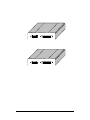
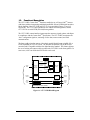
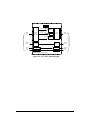
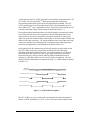
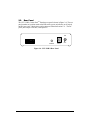
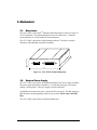
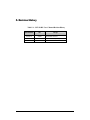
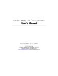
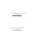
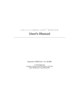
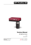
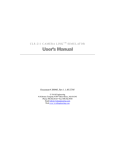
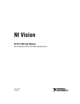
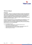
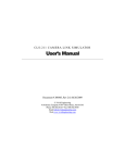
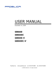
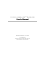
C LT- 3 5 1 R / L C A M E R A L I N K T M T R A N S L ATO R User’s Manual Document # 200162, Rev 1.1, 8/10/10 Vivid Engineering 418 Boston Turnpike #104 • Shrewsbury, MA 01545 Phone 508.842.0165 • Fax 508.842.8930 Table of Contents 1. Introduction 1 1.1. Overview 1 1.2. Features 3 1.3. Functional Description 4 1.3.1. Mode Switch Settings 8 1.4. Typical Application 9 1.5. Specifications 11 2. Interface 12 2.1. Front Panel Connections 12 2.1.1. Camera Connector Signals 14 2.1.2. Frame Grabber Connector Signals 14 2.1.3. Cable Shield Grounding 15 2.2. Rear Panel 44 3. Mechanical 45 3.1. Dimensions 45 3.2. External Power Supply 45 4. Regulatory Compliance 46 4.1. FCC Compliance Statement 46 4.2. Canadian Compliance Statement 46 5. Revision History 47 1. Introduction 1.1. Overview The CLT-351R and CLT-351L Camera LinkTM 1 Translators enable the use of newer Camera LinkTM cameras with frame grabbers incorporating traditional RS-422 and LVDS digital interfaces. The “R” and “L” versions support RS-422 and LVDS frame grabbers, respectively. The CLT-351’s incorporate an AIA standard 68-pin frame grabber interface2 to maximize the use of standard and existing cables. The CLT-351’s are extremely flexible and can translate a wide range of single-channel, dual-channel, and color “base” configuration Camera LinkTM cameras to AIA-standard parallel digital format using rear-panel mode switch settings. Housed in sturdy, compact aluminum enclosures, the CLT-351R/L Camera LinkTM Translators are well suited for industrial environments. The Camera LinkTM interface standard enables the interoperability of cameras and frame grabbers, regardless of vendor. The Automated Imaging Association (AIA) sponsors the Camera LinkTM program including the oversight Camera Link Committee, the self-certification program, and the product registry. The Camera LinkTM specification may be downloaded from the AIA website, found at www.machinevisiononline.org 1 Standard BSR/AIA A15.08/3-199X “Automated Vision Components - Cameras - AIA Monochrome Digital Interface Specification”. Available from Automated Imaging Association P.O. Box 3724, Ann Arbor, MI 48106 2 Camera LinkTM is a trademark of the Automated Imaging Association 1 Vivid Engineering CAMERA Vivid Engineering CAMERA Camera Link Translator CLT-351R RS-422 FRAME GRABBER Camera Link Translator LVDS FRAME GRABBER 2 CLT-351L 1.2. Features • Enable use of Camera LinkTM cameras with RS-422 and LVDS frame grabbers • Interfaces to a wide range of single-channel, dual-channel, and color Camera LinkTM cameras • AIA standard 68-pin frame grabber interface to maximize reuse of existing/standard cables • “R” version supports RS-422 frame grabbers • “L” version supports LVDS frame grabbers • 66 MHz max pixel clock rate for “L” version • 32 MHz max pixel clock rate for “R” version • Rear-panel switch mode selection • Programmable frame grabber pixel clock phase • Selectable frame grabber timing signal polarities • Sturdy, compact aluminum enclosure • External power supply included • 3-year warrantee 3 1.3. Functional Description The CLT-351R/L Camera LinkTM Translators enable the use of Camera LinkTM cameras with frame grabbers incorporating traditional parallel RS-422 and LVDS digital interfaces. Block diagrams of the CLT-351R and CLT-351L are provided in Figures 1-1 and 1-2, respectively. The CLT-351R is intended for use with RS-422 frame grabbers, and the CLT-351L for use with LVDS (EIA-644) frame grabbers. The CLT-351R/L camera interface incorporates the connector, signals, pinout, and chipset in compliance with the Camera LinkTM specification. The CLT-351R/L incorporates the “base” configuration signal set, consisting of video data, camera control, and serial communications. The frame grabber interface outputs video data in parallel digital format using RS-422 or LVDS, depending on CLT351 version. The interface incorporates a 68-pin SCSI-style connector and is compatible with the AIA digital interface standard. This feature supports the use of existing AIA camera cables to connect the CLT351R/L to the frame grabber. In some cases, a low cost off-the-shelf SCSI cable can be used Mode Select Switch Pixel Data Channel Link Receiver Frame Valid, Line Valid Polarity Select Serial Comm Link Video Data Phase Shifter Clock Camera Control RS-422 RS-422 RS-422 Receivers Receivers Xmtrs LVDS Transmitter RS-422 Receiver LVDS Rcvr RS-422 Xmtr LVDS Xmtr RS-422 Rcvr CLT-351R Camera LinkTM Translator Figure 1-1: CLT-351R Block Diagram 4 Camera Control Serial Comm Link To RS-422 Frame Grabber To Camera LinkTM Camera Video Data Pixel Alignment Mode Select Switch Pixel Data Channel Link Receiver Frame Valid, Line Valid Polarity Select Serial Comm Link Video Data Phase Shifter Clock Camera Control RS-422 RS-422 LVDS Receivers Receivers Xmtrs LVDS Transmitter LVDS Receiver LVDS Rcvr LVDS Xmtr LVDS Xmtr LVDS Rcvr CLT-351L Camera LinkTM Translator Figure 1-2: CLT-351L: Block Diagram 5 Camera Control Serial Comm Link To LVDS Frame Grabber To Camera LinkTM Camera Video Data Pixel Alignment A mode switch on the CLT-351R/L rear-panel is used to identify camera data format. The CLT-351R/L receives Camera LinkTM camera data and maps the pixels into the corresponding parallel format per the 68-pin AIA digital interface standard. The CLT351R/L supports 8/10/12/14/16-bit single-channel, 8/10/12-bit dual-channel, and 8-bit color Camera LinkTM “base” configuration cameras. Four mode switch positions are used to indicate camera data format. Switch settings are defined in Section 1.3.1. Frame grabber timing signal characteristics are selected using the rear-panel mode switch. One switch position is used to select the polarity of the line valid signal, and a second switch position is used to select the polarity of the frame valid signal. In most cases, a “high” state on the line enable and frame enable signals is used to envelope valid lines and frames of video data, respectively. The settings enable the user to select either active-high or active-low polarities for each timing signal. Note that the frame enable signal is not used in line scan applications. Switch settings are defined in Section 1.3.1. Frame grabber pixel clock characteristics are selected using the rear-panel mode switch. The CLT-351R/L incorporates a phase shifter to optimize the clock /data timing relationship for the frame grabber being used. Two switch positions are used to select pixel clock phase shift. In most cases, the 0 degree phase shift setting is used which centers the rising edge of the pixel clock within the valid pixel/timing data interval. Alternatively, clock phase shifts of 90, 180, and 270 degrees are supported. The pixel clock phase shifter characteristics are illustrated in Figure 1-3. Switch settings are defined in Section 1.3.1. Pixel Data & Timing Signals Valid Pixel & Timing Data Pixel Clock w/ 0o shift Pixel Clock w/ 90o shift Pixel Clock w/ 180o shift Pixel Clock w/ 270o shift Figure 1-3: Pixel Clock Phase Options The CLT-351R/L receives up-to four camera control signals from the frame grabber in RS-422 or LVDS, depending on CLT-351 version. The camera control signals are then 6 retransmitted to the Camera LinkTM camera using LVDS signaling. When the CLT351R/L is operated in one of the single-channel modes (1x8, 1x10, 1x12, 1x14, 1x16), all four camera control signals are received from the frame grabber and routed to the camera. In the dual-channel (2x8, 2x10, 2x12) and color (3x8) modes, the number of camera control lines in the frame grabber’s AIA interface is reduced to allow for added pixel data. In dual-channel and color modes, only one camera control signal (CC1) is supported. The CLT-351R/L routes the serial communication signals between the camera and the frame grabber. This supports host computer access to mode control and status registers in the Camera LinkTM camera via the serial link built-into the AIA interface. The CLT351R/L camera interface incorporates LVDS devices for the serial communication signals. The frame grabber interface serial signals are implemented using LVDS or RS-422 devices, depending on CLT-351 version. The CLT-351R/L is powered by an external wall plug-in power supply (included). 7 1.3.1. Mode Switch Settings The CLT-351R/L incorporates a rear-panel mode select switch. The switch allows the user to identify pixel data, timing signal, and clock characteristics. The mode switch has eight positions. The functional assignments are defined in Figure 1-4. 1 2 3 4 5 6 7 8 00 01 11 10 Clock Phase Shifter - 0o (most common) - 90o - 180o - 270o 0 1 Frame Valid Polarity - active-high (most common) - active-low 0 1 Line Valid Polarity - active-high (most common) - active-low 0000 0001 0010 0011 0100 1000 1001 1101 1101 Pixel Data Format - 8-bit, single-channel - 10-bit, single-channel - 12-bit, single-channel - 14-bit, single-channel - 16-bit, single-channel - 8-bit, dual-channel - 10-bit, dual-channel - 12-bit, dual-channel - 8-bit, color (8x3) 0 = "down" switch position 1 = "up" switch position Figure 1-4: CLT-351R/L Mode Switch Definition 8 1.4. Typical Application A typical CLT-351R/L application is shown in Figure 1-5. A Camera LinkTM camera is connected to the CLT-351R using a standard Camera LinkTM cable. The CLT-351R is then connected to the frame grabber using an existing camera cable incorporating the AIA-standard 68-pin connector. Note: If the frame grabber incorporates the AIA interface and supports the serial link, a standard low-cost SCSI cable may be used between the camera and the CLT-351R The Camera LinkTM “base” configuration camera in this example is, 8-bit, dual-channel, area-scan with a 20MHz pixel clock. The RS-422 frame grabber is programmed for area-scan, dual-channel, 8-bit mode. The frame enable and line enable timing signals are conventional active-high, and data is sampled using the rising clock edge. The pixel clock rate is set at 20MHz and video timing is set to match camera characteristics. Camera control signal CC1 is routed from the frame grabber, through the CLT-351R, to the camera for use as an EXSYNC pulse, exposure control, etc. If a serial port is built-into the frame grabber, it may be used to control and monitor camera functions. In some cases, the camera cable between the frame grabber and the CLT-351R may break-out the serial signals for connection to a separate serial communications port in the PC. CLT-351R Camera LinkTM Translator Vivid Engineering CAMERA Camera LinkTM Camera Camera Link Translator CLT-351R RS-422 FRAME GRABBER Existing Camera Cable or Standard SCSI Cable Camera LinkTM Cable Figure 1-5: CLT-351R/L Typical Application 9 RS-422 Frame Grabber 1 2 3 4 5 6 7 8 00 0 0 1 1000 Clock Phase Shifter - 0o (most common) Frame Valid Polarity - active-high (most common) Line Valid Polarity - active-high (most common) Pixel Data Format - 8-bit, dual-channel 0 = "down" switch position 1 = "up" switch position Figure 1-6: Example Mode Settings 10 1.5. Specifications Table 1-1: CLT-351R/L Specifications Feature Specification TM Camera Interface Camera Link Spec “base” configuration Camera Connector 26-pin MDR type Frame Grabber Interface AIA digital interface standard - “R” version = RS-422 - “L” version = LVDS (EIA-644) Frame Grabber Connector 68-pin HD type (SCSI-3) Frequency Range 20 - 66 MHz (“L” version) 20 - 32 MHz (“R” version) Mode Selection Rear-panel 8-position DIP switch Chipset National Semi. DS90CR286A Power Supply External 6 VDC Wall Transformer Power Jack 2.1 x 5.5 mm, center-positive Power Requirements - “R” version = 1100 mA at 6 VDC (typical) - “L” version = 400 mA at 6 VDC (typical) Cabinet Dimensions 5.28” (L) x 1.12” (H) x 6.13” (D) Weight 14 oz Operating Temperature Range 0 to 50° C Storage Temperature Range -25 to 75° C Relative Humidity 0 to 90%, non-condensing 11 2. Interface 2.1. Front Panel Connections A CLT-351R/L Camera LinkTM Translator front panel is shown in Figure 2-1 (CLT-351R shown). The front panel contains two video connectors; one for connecting to the camera and one for connecting to the frame grabber. The camera connector is a 26-pin MDR type (MDR-26), 3M p/n 10226-55G3PC as specified in the Camera LinkTM Spec. Figure 2-2 identifies the MDR-26 pin positions. The frame grabber connector is a 68-pin SCSI-3 type (HD68), Tyco p/n 5787170-7. Figure 2-3 identifies the HD68 pin positions. Vivid Engineering Camera Link Translator CAMERA RS-422 FRAME GRABBER Figure 2-1: CLT-351R Front Panel 12 CLT-351R pin 13 pin 1 pin 26 pin 14 Figure 2-2: MDR-26 Connector Pin Positions pin 34 pin 1 pin 68 pin 35 Figure 2-3: HD68 Connector Pin Positions 13 2.1.1. Camera Connector Signals The MDR-26 camera connector signal assignment is compliant with the Camera LinkTM Specification for the “base” configuration. Table 2-1 identifies the signal assignment for the MDR-26 camera connector. Note that the connector pin assignments are as defined for the frame grabber interface in the Camera LinkTM Specification. This provides compatibility with standard Camera LinkTM cables 2.1.2. Frame Grabber Connector Signals The HD68 frame grabber connector signal assignments are compatible with the AIA digital interface standard. The signal assignment is determined by the pixel data format, indicated with the mode switch. Tables 2-2 through 2-6 identify the HD68 frame grabber connector signal assignment for single-channel pixel data modes (1x8, 1x10, 1x12, 1x14, and 1x16). Tables 2-7 through 2-9 identify the signal assignment for dual-channel modes (2x8, 2x10, 2x12), and Table 2-10 identifies the signal assignment for color mode (3x8). Note that in the single channel modes, the CLT-351R/L receives four camera control signals from the frame grabber (CC1, CC2, CC3, CC4) and retransmits the signals to the camera. In the dual-channel and color modes, the CLT-351R/L only receives and retransmits CC1. 14 2.1.3. Cable Shield Grounding Camera and frame grabber cable “outer” shields are connected to the CLT-351R/L aluminum case. Case and endplate contacting surfaces are unpainted, providing a Faraday cage to shield internal circuitry. The case is isolated from the CLT-351R/L circuitry and the cable “inner” shields, avoiding possible safety concerns. The frame grabber cable “inner” shield connects to circuit digital ground, maintaining signal reference levels between the CLT-351R/L and the frame grabber. The Camera LinkTM Specification recommends that a provision be incorporated into frame grabbers that enable the inner shields be tied to digital ground either directly, or through a parallel R/C network. In the CLT-351R/L, the camera connector represents the Camera LinkTM frame grabber interface. To incorporate this flexibility, the CLT351R/L ties the inner shields from the camera connector to digital ground through 0ohm resistors. If necessary, the 0-ohm resistors may be replaced with a parallel RC network. 15 Table 2-1: Camera Connector Camera Connector Pin # (frame grabber pinout) Signal Direction Notes Inner shield 1 N/A tied to digital ground Inner shield 14 N/A tied to digital ground X0- 25 CAM → CLT351 X0+ 12 CAM → CLT351 TM Camera Link Signal Name X1- 24 CAM → CLT351 X1+ 11 CAM → CLT351 X2- 23 CAM → CLT351 X2+ 10 CAM → CLT351 Xclk- 22 CAM → CLT351 Xclk+ 9 CAM → CLT351 X3- 21 CAM → CLT351 1 1 X3+ 8 CAM → CLT351 SerTC+ 20 CLT351 → CAM serial comm, FG to cam SerTC- 7 CLT351 → CAM “ SerTFG- 19 CAM → CLT351 serial comm, cam to FG “ SerTFG+ 6 CAM → CLT351 CC1- 18 CLT351 → CAM CC1+ 5 CLT351 → CAM CC2+ 17 CLT351 → CAM single-channel modes only CC2- 4 CLT351 → CAM “ CC3- 16 CLT351 → CAM single-channel modes only CC3+ 3 CLT351 → CAM “ CC4+ 15 CLT351 → CAM single-channel modes only CC4- 2 CLT351 → CAM “ Inner shield 13 N/A tied to digital ground Inner shield 26 N/A tied to digital ground “FG” = Frame Grabber 1 See Section 2.1.3 16 1 1 Table 2-2: Frame Grabber Connector, 8-bit Single-Channel Mode Camera Interface Signal Name Camera Interface Connector Pin Signal Direction Notes Ground 1 N/A tied to digital ground Ground tied to digital ground 35 N/A 1 2 CLT351 → FG 1 A7 - 36 CLT351 → FG A6 + 3 CLT351 → FG A6 - 37 CLT351 → FG A5 + 4 CLT351 → FG A5 - 38 CLT351 → FG A4 + 5 CLT351 → FG A4 - 39 CLT351 → FG A3 + 6 CLT351 → FG A3 - 40 CLT351 → FG A2 + 7 CLT351 → FG A2 - 41 CLT351 → FG A1 + 8 CLT351 → FG A1 - 42 CLT351 → FG A0 + 9 CLT351 → FG A7 + A0 - 43 CLT351 → FG Unused Output 10 CLT351 → FG Unused Output 44 CLT351 → FG Unused Output 11 CLT351 → FG Unused Output 45 CLT351 → FG Ground 12 N/A tied to digital ground Ground 46 N/A tied to digital ground Unused Output 13 CLT351 → FG Unused Output 47 CLT351 → FG Unused Output 14 CLT351 → FG Unused Output 48 CLT351 → FG Unused Output 15 CLT351 → FG Unused Output 49 CLT351 → FG Unused Output 16 CLT351 → FG 17 Unused Output 50 CLT351 → FG Not Used 17 N/A Not Used 51 N/A Unused Output 18 CLT351 → FG CLT351 outputs logic “0” Unused Output 52 CLT351 → FG “ Unused Output 19 CLT351 → FG Unused Output 53 CLT351 → FG Unused Output 20 CLT351 → FG Unused Output 54 CLT351 → FG Unused Output 21 CLT351 → FG CLT351 outputs logic “0” Unused Output 55 CLT351 → FG “ Serial Control Out + 22 CLT351 → FG serial comm, cam to FG Serial Control Out - 56 CLT351 → FG “ Serial Control In + 23 FG → CLT351 serial comm, FG to cam Serial Control In - 57 FG → CLT351 “ Unused Output 24 CLT351 → FG CLT351 outputs logic “0” Unused Output 58 CLT351 → FG “ Frame Enable + 25 CLT351 → FG “frame valid” Frame Enable - 59 CLT351 → FG “ Line Enable + 26 CLT351 → FG “line valid” Line Enable - 60 CLT351 → FG “ Unused Output 27 CLT351 → FG CLT351 outputs logic “0” Unused Output 61 CLT351 → FG “ Unused Output 28 CLT351 → FG CLT351 outputs logic “0” Unused Output 62 CLT351 → FG “ Pixel Strobe + 29 CLT351 → FG “pixel clock” Pixel Strobe - 63 CLT351 → FG “ Mode Control 0 + 30 FG → CLT351 CC1 from FG Mode Control 0 - 64 FG → CLT351 ” Mode Control 1 + 31 FG → CLT351 CC2 from FG Mode Control 1 - 65 FG → CLT351 ” Mode Control 2 + 32 FG → CLT351 CC3 from FG Mode Control 2 - 66 FG → CLT351 ” Mode Control 3 + 33 FG → CLT351 CC4 from FG Mode Control 3 - 67 FG → CLT351 ” Ground 34 N/A tied to digital ground 18 Ground 68 N/A 1 Pixel Data MSB “FG” = Frame Grabber 19 tied to digital ground Table 2-3: Frame Grabber Connector, 10-bit Single-Channel Mode Camera Interface Signal Name Camera Interface Connector Pin Signal Direction Notes Ground 1 N/A tied to digital ground Ground tied to digital ground 35 N/A 1 2 CLT351 → FG 1 A9 - 36 CLT351 → FG A8 + 3 CLT351 → FG A8 - 37 CLT351 → FG A7 + 4 CLT351 → FG A7 - 38 CLT351 → FG A6 + 5 CLT351 → FG A6 - 39 CLT351 → FG A5 + 6 CLT351 → FG A5 - 40 CLT351 → FG A4 + 7 CLT351 → FG A4 - 41 CLT351 → FG A3 + 8 CLT351 → FG A3 - 42 CLT351 → FG A2 + 9 CLT351 → FG A9 + A2 - 43 CLT351 → FG A1 + 10 CLT351 → FG A1 - 44 CLT351 → FG A0 + 11 CLT351 → FG A0 - 45 CLT351 → FG Ground 12 N/A tied to digital ground Ground 46 N/A tied to digital ground Unused Output 13 CLT351 → FG Unused Output 47 CLT351 → FG Unused Output 14 CLT351 → FG Unused Output 48 CLT351 → FG Unused Output 15 CLT351 → FG Unused Output 49 CLT351 → FG Unused Output 16 CLT351 → FG 20 Unused Output 50 CLT351 → FG Not Used 17 N/A Not Used 51 N/A Unused Output 18 CLT351 → FG CLT351 outputs logic “0” Unused Output 52 CLT351 → FG “ Unused Output 19 CLT351 → FG Unused Output 53 CLT351 → FG Unused Output 20 CLT351 → FG Unused Output 54 CLT351 → FG Unused Output 21 CLT351 → FG CLT351 outputs logic “0” Unused Output 55 CLT351 → FG “ Serial Control Out + 22 CLT351 → FG serial comm, cam to FG Serial Control Out - 56 CLT351 → FG “ Serial Control In + 23 FG → CLT351 serial comm, FG to cam Serial Control In - 57 FG → CLT351 “ Unused Output 24 CLT351 → FG CLT351 outputs logic “0” Unused Output 58 CLT351 → FG “ Frame Enable + 25 CLT351 → FG “frame valid” Frame Enable - 59 CLT351 → FG “ Line Enable + 26 CLT351 → FG “line valid” Line Enable - 60 CLT351 → FG “ Unused Output 27 CLT351 → FG CLT351 outputs logic “0” Unused Output 61 CLT351 → FG “ Unused Output 28 CLT351 → FG CLT351 outputs logic “0” Unused Output 62 CLT351 → FG “ Pixel Strobe + 29 CLT351 → FG “pixel clock” Pixel Strobe - 63 CLT351 → FG “ Mode Control 0 + 30 FG → CLT351 CC1 from FG Mode Control 0 - 64 FG → CLT351 ” Mode Control 1 + 31 FG → CLT351 CC2 from FG Mode Control 1 - 65 FG → CLT351 ” Mode Control 2 + 32 FG → CLT351 CC3 from FG Mode Control 2 - 66 FG → CLT351 ” Mode Control 3 + 33 FG → CLT351 CC4 from FG Mode Control 3 - 67 FG → CLT351 ” Ground 34 N/A tied to digital ground 21 Ground 68 N/A 1 Pixel Data MSB “FG” = Frame Grabber 22 tied to digital ground Table 2-4: Frame Grabber Connector, 12-bit Single-Channel Mode Camera Interface Signal Name Camera Interface Connector Pin Signal Direction Notes Ground 1 N/A tied to digital ground Ground tied to digital ground 35 N/A 1 2 CLT351 → FG 1 A11 - 36 CLT351 → FG A10 + 3 CLT351 → FG A10 - 37 CLT351 → FG A9 + 4 CLT351 → FG A9 - 38 CLT351 → FG A8 + 5 CLT351 → FG A8 - 39 CLT351 → FG A7 + 6 CLT351 → FG A7 - 40 CLT351 → FG A6 + 7 CLT351 → FG A6 - 41 CLT351 → FG A5 + 8 CLT351 → FG A5 - 42 CLT351 → FG A4 + 9 CLT351 → FG A11 + A4 - 43 CLT351 → FG A3 + 10 CLT351 → FG A3 - 44 CLT351 → FG A2 + 11 CLT351 → FG A2 - 45 CLT351 → FG Ground 12 N/A tied to digital ground Ground 46 N/A tied to digital ground A1 + 13 CLT351 → FG A1 - 47 CLT351 → FG A0 + 14 CLT351 → FG A0 - 48 CLT351 → FG Unused Output 15 CLT351 → FG Unused Output 49 CLT351 → FG Unused Output 16 CLT351 → FG 23 Unused Output 50 CLT351 → FG Not Used 17 N/A Not Used 51 N/A Unused Output 18 CLT351 → FG CLT351 outputs logic “0” Unused Output 52 CLT351 → FG “ Unused Output 19 CLT351 → FG Unused Output 53 CLT351 → FG Unused Output 20 CLT351 → FG Unused Output 54 CLT351 → FG Unused Output 21 CLT351 → FG CLT351 outputs logic “0” Unused Output 55 CLT351 → FG “ Serial Control Out + 22 CLT351 → FG serial comm, cam to FG Serial Control Out - 56 CLT351 → FG “ Serial Control In + 23 FG → CLT351 serial comm, FG to cam Serial Control In - 57 FG → CLT351 “ Unused Output 24 CLT351 → FG CLT351 outputs logic “0” Unused Output 58 CLT351 → FG “ Frame Enable + 25 CLT351 → FG “frame valid” Frame Enable - 59 CLT351 → FG “ Line Enable + 26 CLT351 → FG “line valid” Line Enable - 60 CLT351 → FG “ Unused Output 27 CLT351 → FG CLT351 outputs logic “0” Unused Output 61 CLT351 → FG “ Unused Output 28 CLT351 → FG CLT351 outputs logic “0” Unused Output 62 CLT351 → FG “ Pixel Strobe + 29 CLT351 → FG “pixel clock” Pixel Strobe - 63 CLT351 → FG “ Mode Control 0 + 30 FG → CLT351 CC1 from FG Mode Control 0 - 64 FG → CLT351 ” Mode Control 1 + 31 FG → CLT351 CC2 from FG Mode Control 1 - 65 FG → CLT351 ” Mode Control 2 + 32 FG → CLT351 CC3 from FG Mode Control 2 - 66 FG → CLT351 ” Mode Control 3 + 33 FG → CLT351 CC4 from FG Mode Control 3 - 67 FG → CLT351 ” Ground 34 N/A tied to digital ground 24 Ground 68 N/A 1 Pixel Data MSB “FG” = Frame Grabber 25 tied to digital ground Table 2-5: Frame Grabber Connector, 14-bit Single-Channel Mode Camera Interface Signal Name Camera Interface Connector Pin Signal Direction Notes Ground 1 N/A tied to digital ground Ground tied to digital ground 35 N/A 1 2 CLT351 → FG 1 A13 - 36 CLT351 → FG A12 + 3 CLT351 → FG A12 - 37 CLT351 → FG A11 + 4 CLT351 → FG A11 - 38 CLT351 → FG A10 + 5 CLT351 → FG A10 - 39 CLT351 → FG A9 + 6 CLT351 → FG A9 - 40 CLT351 → FG A8 + 7 CLT351 → FG A8 - 41 CLT351 → FG A7 + 8 CLT351 → FG A7 - 42 CLT351 → FG A6 + 9 CLT351 → FG A13 + A6 - 43 CLT351 → FG A5 + 10 CLT351 → FG A5 - 44 CLT351 → FG A4 + 11 CLT351 → FG A4 - 45 CLT351 → FG Ground 12 N/A tied to digital ground Ground 46 N/A tied to digital ground A3 + 13 CLT351 → FG A3 - 47 CLT351 → FG A2 + 14 CLT351 → FG A2 - 48 CLT351 → FG A1 + 15 CLT351 → FG A1 - 49 CLT351 → FG A0 + 16 CLT351 → FG 26 A0 - 50 CLT351 → FG Not Used 17 N/A Not Used 51 N/A Unused Output 18 CLT351 → FG CLT351 outputs logic “0” Unused Output 52 CLT351 → FG “ Unused Output 19 CLT351 → FG Unused Output 53 CLT351 → FG Unused Output 20 CLT351 → FG Unused Output 54 CLT351 → FG Unused Output 21 CLT351 → FG CLT351 outputs logic “0” Unused Output 55 CLT351 → FG “ Serial Control Out + 22 CLT351 → FG serial comm, cam to FG Serial Control Out - 56 CLT351 → FG “ Serial Control In + 23 FG → CLT351 serial comm, FG to cam Serial Control In - 57 FG → CLT351 “ Unused Output 24 CLT351 → FG CLT351 outputs logic “0” Unused Output 58 CLT351 → FG “ Frame Enable + 25 CLT351 → FG “frame valid” Frame Enable - 59 CLT351 → FG “ Line Enable + 26 CLT351 → FG “line valid” Line Enable - 60 CLT351 → FG “ Unused Output 27 CLT351 → FG CLT351 outputs logic “0” Unused Output 61 CLT351 → FG “ Unused Output 28 CLT351 → FG CLT351 outputs logic “0” Unused Output 62 CLT351 → FG “ Pixel Strobe + 29 CLT351 → FG “pixel clock” Pixel Strobe - 63 CLT351 → FG “ Mode Control 0 + 30 FG → CLT351 CC1 from FG Mode Control 0 - 64 FG → CLT351 ” Mode Control 1 + 31 FG → CLT351 CC2 from FG Mode Control 1 - 65 FG → CLT351 ” Mode Control 2 + 32 FG → CLT351 CC3 from FG Mode Control 2 - 66 FG → CLT351 ” Mode Control 3 + 33 FG → CLT351 CC4 from FG Mode Control 3 - 67 FG → CLT351 ” Ground 34 N/A tied to digital ground 27 Ground 68 N/A 1 Pixel Data MSB “FG” = Frame Grabber 28 tied to digital ground Table 2-6: Frame Grabber Connector, 16-bit Single-Channel Mode Camera Interface Signal Name Camera Interface Connector Pin Signal Direction Notes Ground 1 N/A tied to digital ground Ground tied to digital ground 35 N/A 1 2 CLT351 → FG 1 A15 - 36 CLT351 → FG A14 + 3 CLT351 → FG A14 - 37 CLT351 → FG A13 + 4 CLT351 → FG A13 - 38 CLT351 → FG A12 + 5 CLT351 → FG A12 - 39 CLT351 → FG A11 + 6 CLT351 → FG A11 - 40 CLT351 → FG A10 + 7 CLT351 → FG A10 - 41 CLT351 → FG A69 + 8 CLT351 → FG A9 - 42 CLT351 → FG A8 + 9 CLT351 → FG A15 + A8 - 43 CLT351 → FG A7 + 10 CLT351 → FG A7 - 44 CLT351 → FG A6 + 11 CLT351 → FG A6 - 45 CLT351 → FG Ground 12 N/A tied to digital ground Ground 46 N/A tied to digital ground A5 + 13 CLT351 → FG A5 - 47 CLT351 → FG A4 + 14 CLT351 → FG A4 - 48 CLT351 → FG A3 + 15 CLT351 → FG A3 - 49 CLT351 → FG A2 + 16 CLT351 → FG 29 A2 - 50 CLT351 → FG Not Used 17 N/A Not Used 51 N/A Unused Output 18 CLT351 → FG CLT351 outputs logic “0” “ Unused Output 52 CLT351 → FG A1 + 19 CLT351 → FG A1 - 53 CLT351 → FG A0 + 20 CLT351 → FG A0 - 54 CLT351 → FG Unused Output 21 CLT351 → FG CLT351 outputs logic “0” Unused Output 55 CLT351 → FG “ Serial Control Out + 22 CLT351 → FG serial comm, cam to FG Serial Control Out - 56 CLT351 → FG “ Serial Control In + 23 FG → CLT351 serial comm, FG to cam Serial Control In - 57 FG → CLT351 “ Unused Output 24 CLT351 → FG CLT351 outputs logic “0” Unused Output 58 CLT351 → FG “ Frame Enable + 25 CLT351 → FG “frame valid” Frame Enable - 59 CLT351 → FG “ Line Enable + 26 CLT351 → FG “line valid” Line Enable - 60 CLT351 → FG “ Unused Output 27 CLT351 → FG CLT351 outputs logic “0” Unused Output 61 CLT351 → FG “ Unused Output 28 CLT351 → FG CLT351 outputs logic “0” Unused Output 62 CLT351 → FG “ Pixel Strobe + 29 CLT351 → FG “pixel clock” Pixel Strobe - 63 CLT351 → FG “ Mode Control 0 + 30 FG → CLT351 CC1 from FG Mode Control 0 - 64 FG → CLT351 ” Mode Control 1 + 31 FG → CLT351 CC2 from FG Mode Control 1 - 65 FG → CLT351 ” Mode Control 2 + 32 FG → CLT351 CC3 from FG Mode Control 2 - 66 FG → CLT351 ” Mode Control 3 + 33 FG → CLT351 CC4 from FG Mode Control 3 - 67 FG → CLT351 ” Ground 34 N/A tied to digital ground 30 Ground 68 N/A 1 Pixel Data MSB “FG” = Frame Grabber 31 tied to digital ground Table 2-7: Frame Grabber Connector, 8-bit Dual-Channel Mode Camera Interface Signal Name Camera Interface Connector Pin Signal Direction Notes Ground 1 N/A tied to digital ground Ground tied to digital ground 35 N/A 1 2 CLT351 → FG 1 A7 - 36 CLT351 → FG A6 + 3 CLT351 → FG A6 - 37 CLT351 → FG A5 + 4 CLT351 → FG A5 - 38 CLT351 → FG A4 + 5 CLT351 → FG A4 - 39 CLT351 → FG A3 + 6 CLT351 → FG A3 - 40 CLT351 → FG A2 + 7 CLT351 → FG A2 - 41 CLT351 → FG A1 + 8 CLT351 → FG A1 - 42 CLT351 → FG A0 + 9 CLT351 → FG A0 - A7 + 43 CLT351 → FG 2 10 CLT351 → FG 2 B7 - 44 CLT351 → FG B6 + 11 CLT351 → FG B7 + B6 - 45 CLT351 → FG Ground 12 N/A tied to digital ground Ground 46 N/A tied to digital ground B5 + 13 CLT351 → FG B5 - 47 CLT351 → FG B4 + 14 CLT351 → FG B4 - 48 CLT351 → FG B3 + 15 CLT351 → FG B3 - 49 CLT351 → FG B2 + 16 CLT351 → FG 32 B2 - 50 CLT351 → FG Not Used 17 N/A Not Used 51 N/A Unused Output 18 CLT351 → FG CLT351 outputs logic “0” “ Unused Output 52 CLT351 → FG B1 + 19 CLT351 → FG B1 - 53 CLT351 → FG B0 + 20 CLT351 → FG B0 - 54 CLT351 → FG Unused Output 21 CLT351 → FG Unused Output 55 CLT351 → FG Serial Control Out + 22 CLT351 → FG serial comm, cam to FG Serial Control Out - 56 CLT351 → FG “ Serial Control In + 23 FG → CLT351 serial comm, FG to cam Serial Control In - 57 FG → CLT351 “ Unused Output 24 CLT351 → FG CLT351 outputs logic “0” Unused Output 58 CLT351 → FG “ Frame Enable + 25 CLT351 → FG “frame valid” Frame Enable - 59 CLT351 → FG “ Line Enable + 26 CLT351 → FG “line valid” Line Enable - 60 CLT351 → FG “ Unused Output 27 CLT351 → FG CLT351 outputs logic “0” Unused Output 61 CLT351 → FG “ Unused Output 28 CLT351 → FG CLT351 outputs logic “0” Unused Output 62 CLT351 → FG “ Pixel Strobe + 29 CLT351 → FG “pixel clock” Pixel Strobe - 63 CLT351 → FG “ Expose + 30 FG → CLT351 CC1 from FG Expose - 64 FG → CLT351 ” Unused Output 31 CLT351 → FG Unused Output 65 CLT351 → FG Unused Output 32 CLT351 → FG Unused Output 66 CLT351 → FG Unused Output 33 CLT351 → FG Unused Output 67 CLT351 → FG Ground 34 N/A 33 tied to digital ground Ground 68 N/A 1 Pixel “A” MSB 2 Pixel “B” MSB “FG” = Frame Grabber 34 tied to digital ground Table 2-8: Frame Grabber Connector, 10-bit Dual-Channel Mode Camera Interface Signal Name Camera Interface Connector Pin Signal Direction Notes Ground 1 N/A tied to digital ground Ground tied to digital ground 35 N/A 1 2 CLT351 → FG 1 A9 - 36 CLT351 → FG A8 + 3 CLT351 → FG A8 - 37 CLT351 → FG A7 + 4 CLT351 → FG A7 - 38 CLT351 → FG A6 + 5 CLT351 → FG A6 - 39 CLT351 → FG A5 + 6 CLT351 → FG A5 - 40 CLT351 → FG A4 + 7 CLT351 → FG A4 - 41 CLT351 → FG A3 + 8 CLT351 → FG A3 - 42 CLT351 → FG A2 + 9 CLT351 → FG A2 - A9 + 43 CLT351 → FG 2 10 CLT351 → FG 2 B9 - 44 CLT351 → FG B8 + 11 CLT351 → FG B9 + B8 - 45 CLT351 → FG Ground 12 N/A tied to digital ground Ground 46 N/A tied to digital ground B7 + 13 CLT351 → FG B7 - 47 CLT351 → FG B6 + 14 CLT351 → FG B6 - 48 CLT351 → FG B5 + 15 CLT351 → FG B5 - 49 CLT351 → FG B4 + 16 CLT351 → FG 35 B4 - 50 CLT351 → FG Not Used 17 N/A Not Used 51 N/A Unused Output 18 CLT351 → FG CLT351 outputs logic “0” “ Unused Output 52 CLT351 → FG B3 + 19 CLT351 → FG B3 - 53 CLT351 → FG B2 + 20 CLT351 → FG B2 - 54 CLT351 → FG A1 + 21 CLT351 → FG A1 - 55 CLT351 → FG Serial Control Out + 22 CLT351 → FG serial comm, cam to FG Serial Control Out - 56 CLT351 → FG “ Serial Control In + 23 FG → CLT351 serial comm, FG to cam Serial Control In - 57 FG → CLT351 “ Unused Output 24 CLT351 → FG CLT351 outputs logic “0” Unused Output 58 CLT351 → FG “ Frame Enable + 25 CLT351 → FG “frame valid” Frame Enable - 59 CLT351 → FG “ Line Enable + 26 CLT351 → FG “line valid” Line Enable - 60 CLT351 → FG “ Unused Output 27 CLT351 → FG CLT351 outputs logic “0” Unused Output 61 CLT351 → FG “ Unused Output 28 CLT351 → FG CLT351 outputs logic “0” Unused Output 62 CLT351 → FG “ Pixel Strobe + 29 CLT351 → FG “pixel clock” Pixel Strobe - 63 CLT351 → FG “ Expose + 30 FG → CLT351 CC1 from FG Expose - 64 FG → CLT351 ” A0 + 31 CLT351 → FG A0 - 65 CLT351 → FG B1 + 32 CLT351 → FG B1 - 66 CLT351 → FG B0 + 33 CLT351 → FG B0 - 67 CLT351 → FG Ground 34 N/A 36 tied to digital ground Ground 68 N/A 1 Pixel “A” MSB 2 Pixel “B” MSB “FG” = Frame Grabber 37 tied to digital ground Table 2-9: Frame Grabber Connector, 12-bit Dual-Channel Mode Camera Interface Signal Name Camera Interface Connector Pin Signal Direction Notes Ground 1 N/A tied to digital ground Ground 35 N/A tied to digital ground A7 + 2 CLT351 → FG A7 - 36 CLT351 → FG A6 + 3 CLT351 → FG A6 - 37 CLT351 → FG A5 + 4 CLT351 → FG A5 - 38 CLT351 → FG A4 + 5 CLT351 → FG A4 - 39 CLT351 → FG A3 + 6 CLT351 → FG A3 - 40 CLT351 → FG A2 + 7 CLT351 → FG A2 - 41 CLT351 → FG A1 + 8 CLT351 → FG A1 - 42 CLT351 → FG A0 + 9 CLT351 → FG A0 - 43 CLT351 → FG 2 10 CLT351 → FG 2 B11 - 44 CLT351 → FG B10 + 11 CLT351 → FG B11 + B10 - 45 CLT351 → FG Ground 12 N/A tied to digital ground Ground 46 N/A tied to digital ground B9 + 13 CLT351 → FG B9 - 47 CLT351 → FG B8 + 14 CLT351 → FG 48 CLT351 → FG B8 1 15 CLT351 → FG A11 - 1 49 CLT351 → FG A10 + 16 CLT351 → FG A11 + 38 A10 - 50 CLT351 → FG Not Used 17 N/A Not Used 51 N/A B3 + 18 CLT351 → FG CLT351 outputs logic “0” “ B3 - 52 CLT351 → FG A9 + 19 CLT351 → FG A9 - 53 CLT351 → FG A8 + 20 CLT351 → FG A8 - 54 CLT351 → FG B7 + 21 CLT351 → FG B7 - 55 CLT351 → FG Serial Control Out + 22 CLT351 → FG serial comm, cam to FG Serial Control Out - 56 CLT351 → FG “ Serial Control In + 23 FG → CLT351 serial comm, FG to cam Serial Control In - 57 FG → CLT351 “ B2 + 24 CLT351 → FG CLT351 outputs logic “0” B2 - 58 CLT351 → FG “ Frame Enable + 25 CLT351 → FG “frame valid” Frame Enable - 59 CLT351 → FG “ Line Enable + 26 CLT351 → FG “line valid” Line Enable - 60 CLT351 → FG “ B1 + 27 CLT351 → FG CLT351 outputs logic “0” B1 - 61 CLT351 → FG “ B0 + 28 CLT351 → FG CLT351 outputs logic “0” B0 - 62 CLT351 → FG “ Pixel Strobe + 29 CLT351 → FG “pixel clock” Pixel Strobe - 63 CLT351 → FG “ Expose + 30 FG → CLT351 CC1 from FG Expose - 64 FG → CLT351 ” B6 + 31 CLT351 → FG B6 - 65 CLT351 → FG B5 + 32 CLT351 → FG B5 - 66 CLT351 → FG B4 + 33 CLT351 → FG B4 - 67 CLT351 → FG Ground 34 N/A 39 tied to digital ground Ground 68 N/A 1 Pixel “A” MSB 2 Pixel “B” MSB “FG” = Frame Grabber 40 tied to digital ground Table 2-10: Frame Grabber Connector, Color Mode Camera Interface Signal Name Camera Interface Connector Pin Signal Direction Notes Ground 1 N/A tied to digital ground Ground tied to digital ground 35 N/A 1 2 CLT351 → FG 1 R7 - 36 CLT351 → FG R6 + 3 CLT351 → FG R6 - 37 CLT351 → FG R5 + 4 CLT351 → FG R5 - 38 CLT351 → FG R4 + 5 CLT351 → FG R4 - 39 CLT351 → FG R3 + 6 CLT351 → FG R3 - 40 CLT351 → FG R2 + 7 CLT351 → FG R2 - 41 CLT351 → FG R1 + 8 CLT351 → FG R1 - 42 CLT351 → FG R0 + 9 CLT351 → FG R7 + R0 - 43 CLT351 → FG 2 10 CLT351 → FG G7 - 2 44 CLT351 → FG G6 + 11 CLT351 → FG G7 + G6 - 45 CLT351 → FG Ground 12 N/A tied to digital ground Ground 46 N/A tied to digital ground G5 + 13 CLT351 → FG G5 - 47 CLT351 → FG G4 + 14 CLT351 → FG G4 - 48 CLT351 → FG G3 + 15 CLT351 → FG G3 - 49 CLT351 → FG G2 + 16 CLT351 → FG 41 G2 - 50 CLT351 → FG Not Used 17 N/A Not Used 51 N/A B3 + 18 CLT351 → FG B3 - 52 CLT351 → FG G1 + 19 CLT351 → FG G1 - 53 CLT351 → FG G0 + 20 CLT351 → FG G0 - 54 CLT351 → FG 3 21 CLT351 → FG 3 55 CLT351 → FG B7 + B7 - Serial Control Out + 22 CLT351 → FG serial comm, cam to FG Serial Control Out - 56 CLT351 → FG “ Serial Control In + 23 FG → CLT351 serial comm, FG to cam Serial Control In - 57 FG → CLT351 “ B2 + 24 CLT351 → FG B2 - 58 CLT351 → FG Frame Enable + 25 CLT351 → FG “frame valid” Frame Enable - 59 CLT351 → FG “ Line Enable + 26 CLT351 → FG “line valid” Line Enable - 60 CLT351 → FG “ B1 + 27 CLT351 → FG B1 - 61 CLT351 → FG B0 + 28 CLT351 → FG B0 - 62 CLT351 → FG Pixel Strobe + 29 CLT351 → FG “pixel clock” Pixel Strobe - 63 CLT351 → FG “ Expose + 30 FG → CLT351 CC1 from FG Expose - 64 FG → CLT351 ” B6 + 31 CLT351 → FG B6 - 65 CLT351 → FG B5 + 32 CLT351 → FG B5 - 66 CLT351 → FG B4 + 33 CLT351 → FG B4 - 67 CLT351 → FG Ground 34 N/A 42 tied to digital ground Ground 68 N/A 1 Pixel “R” MSB (red) 2 Pixel “G” MSB (green) 3 Pixel “B” MSB (blue) “FG” = Frame Grabber 43 tied to digital ground 2.2. Rear Panel The CLT-351R/L Camera LinkTM Translator rear panel is shown in Figure 2-4. The rear panel contains an 8-position mode select DIP switch, power on indicator, on-off switch, and DC power jack. Mode select switch settings are defined in Section 1.3.1. The DC power jack accepts 6 volts DC, center-positive. ON POWER MODE 6 VDC Figure 2-4: CLT-351R/L Rear Panel 44 OFF 3. Mechanical 3.1. Dimensions The CLT-351R/L Camera LinkTM Translator cabinet dimensions are shown in Figure 3-1 (CLT-351R shown). Note that the dimensions are for the cabinet only. Connectors, switch, hardware, etc are not included in the measurements. The CLT-351R/L is housed in a sturdy aluminum enclosure. The body is extruded aluminum, with detachable front and rear endplates. Camera Link Translator CLT-351R 6. 1 1.12" 3" Vivid Engineering CAMERA RS-422 FRAME GRABBER 5.28" Figure 3-1: CLT-351R/L Cabinet Dimensions 3.2. External Power Supply The CLT-351R/L is powered by an external wall-mount 6 VDC power supply (included). The power supply incorporates a standard 2.1 x 5.5 mm DC power plug. Power plug polarity is center-positive. The power supply is UL and CSA listed. An EMI filter is located on the power cord near the DC power plug. The filter suppresses EMI emissions, ensuring regulatory limits are not exceeded. Do not remove the EMI filter. The CLT-351R/L is protected by an internal resettable fuse. 45 4. Regulatory Compliance 4.1. FCC Compliance Statement This equipment has been tested and found to comply with the limits for a Class A digital device, pursuant to Part 15 of the FCC Rules. These limits are designed to provide a reasonable protection against harmful interference when the equipment is operated in a commercial environment. Operation of this equipment in a residential area is likely to cause harmful interference in which case the user will be required to correct the interference at his/her own expense. Changes or modifications not expressly approved by the party responsible for compliance could void the user’s authority to operate the equipment. 4.2. Canadian Compliance Statement This digital apparatus does not exceed the Class A limits for radio noise emissions from digital apparatus set out in the Radio Interference Regulations of the Canadian Department of Communications. 46 5. Revision History Table 5-1: CLT-351R/L User’s Manual Revision History Document ID # Date Changes 200162-1.0 5/29/03 Initial release of manual 200162-1.1 8/10/10 Clarifies connector pin assignments 47