1
| CNC CONTROLS | DRIVE SYSTEMS | LASER SYSTEMS | SERVICE | TRAINING |
FASOPC Server
User’s Manual
D74C-0405-PB01 Edition 01
www.fanucfa.com
888-FANUC-US (888-326-8287)
January 2013
This page intentionally left blank.
FASOPC Server
User’s Manual
D74C-0405-PB01 Edition 01
This page intentionally left blank.
FANUC FA America
Software License Agreement
Version: __1.3__ Dated: _06/29/2011
Per PC Software License
User Site Software License
Site Licensed Software
PLEASE READ THIS SOFTWARE LICENSE AGREEMENT ("LICENSE") CAREFULLY BEFORE
USING THE FANUC FA America (“FANUC”) SOFTWARE. BY CLICKING ON THE "ACCEPT"
BUTTON, OPENING THE PACKAGE, DOWNLOADING THE PRODUCT, OR USING THE EQUIPMENT
THAT CONTAINS THIS PRODUCT, YOU ARE HEREBY CONSENTING TO BE BOUND BY THE
TERMS OF THIS LICENSE. IF YOU DO NOT AGREE TO THE TERMS OF THIS LICENSE, DO NOT
USE, OPEN OR DOWNLOAD THE SOFTWARE. IN SUCH EVENT, YOU MAY RETURN THE
SOFTWARE TO YOUR PLACE OF PURCHASE FOR A REFUND, IF APPLICABLE.
A. FANUC’S GRANT OF LICENSE
1. Types of Licenses:
a. Per PC Software License: Under this type of license, FANUC grants to you (“Customer”) a
nonexclusive, nontransferable and limited license to use and install the FANUC Software
(“Software”) in object code form solely on a single central processing unit (“CPU”) owned or
leased by Customer or otherwise embedded in equipment provided by FANUC. Customer
may not transfer the Software to any other machine except in the following three cases: (i)
when the licensed CPU becomes completely inoperative and unrepairable in which case the
new CPU becomes the sole licensed CPU, or (ii) when the licensed CPU is deemed
temporarily inoperative in which case transferring the Software to another machine is allowed
providing the user is the same user and providing the Software is removed from the
temporary CPU when the original CPU is operative, or (iii) when the Software is permanently
removed from the original CPU in which case the CPU transferred to becomes the sole
licensed CPU.
b. User Site Software License: Under this type of license, FANUC grants to Customer a
nonexclusive, nontransferable and limited license to use and install the Software in object
code form on multiple central processing units owned or leased by Customer or otherwise
embedded in equipment provided by FANUC at one dedicated location. Customer may not
transfer the Software to any other site or location without the prior written consent of FANUC.
c.
Site Licensed Software: Under this type of license, FANUC grants to you (“Customer”) a
nonexclusive, nontransferable and limited license to use and install the FANUC Software in
object code form on multiple central processing units owned or leased by Customer or
otherwise embedded in equipment provided by FANUC at one dedicated location. Customer
may not transfer the Software in any complete form. Certain portions of the Software may be
transferred or moved from the dedicated location as a part of a custom package, but only in
object code form. Any use of any part of the Software for the creation of any derivative,
modification or revised custom application development is strictly prohibited and subject to
applicable penalties as set forth herein.
2. Duplicates and Copies: Customer may make one (1) archival copy of the Software provided
Customer affixes to such copy all copyright, confidentiality, and proprietary notices that appear on
the original. EXCEPT AS EXPRESSLY AUTHORIZED ABOVE, CUSTOMER SHALL NOT:
COPY, IN WHOLE OR IN PART, SOFTWARE OR DOCUMENTATION; MODIFY THE
SOFTWARE; REVERSE COMPILE OR REVERSE ASSEMBLE ALL OR ANY PORTION OF
THE SOFTWARE; OR RENT, LEASE, DISTRIBUTE, SELL, OR CREATE DERIVATIVE WORKS
OF THE SOFTWARE.
3. Updates: If a Software update completely replaces (full install) a previously licensed version of
the Software, Customer may not use both versions of the Software at the same time nor may
Customer transfer them separately.
B. FANUC’S IP RIGHTS AND PROTECTION
Customer acknowledges and agrees that certain aspects of the licensed materials, including the specific
design and structure of individual programs, constitute trade secrets, copyrighted material and other
valuable intellectual property (collectively, “Intellectual Property”) of FANUC. Customer agrees not to
disclose, provide, or otherwise make available such Intellectual Property in any form to any third party
without the prior written consent of FANUC. Customer agrees to implement reasonable security measures
to protect such trade secrets and copyrighted material. Title to Software and documentation shall remain
exclusively with FANUC.
C. FANUC’S LIMITED WARRANTY
FANUC warrants that for a period of ninety (90) days from the date of shipment from FANUC: (i) the
media on which the Software is furnished will be free of defects in materials and workmanship under
normal use; and (ii) the Software substantially conforms to its published specifications. Except for the
foregoing, the Software is provided AS IS. This limited warranty extends only to Customer as the original
licensee. Customer's exclusive remedy and the entire liability of FANUC and its suppliers under this
limited warranty will be, at FANUC's sole and exclusive option, repair, or replacement, of the Software. In
no event does FANUC warrant that the Software is error free or that Customer will be able to operate the
Software without problems or interruptions.
This warranty does not apply if the software (a) has been altered or modified, except by FANUC, (b) has
not been installed, operated, repaired, or maintained in accordance with instructions supplied by FANUC,
(c) has been subjected to abnormal physical or electrical stress, misuse, negligence, or accident, or (d) is
used in ultra-hazardous activities.
EXCEPT AS SPECIFIED IN THIS WARRANTY, ALL EXPRESS OR IMPLIED CONDITIONS,
REPRESENTATIONS, AND WARRANTIES INCLUDING, WITHOUT LIMITATION, ANY IMPLIED
WARRANTY
OF
MERCHANTABILITY,
FITNESS
FOR
A
PARTICULAR
PURPOSE,
NONINFRINGEMENT OR ARISING FROM A COURSE OF DEALING, USAGE, OR TRADE PRACTICE,
ARE HEREBY EXCLUDED TO THE EXTENT ALLOWED BY APPLICABLE LAW.
IN NO EVENT WILL FANUC OR ITS SUPPLIERS BE LIABLE FOR ANY LOST REVENUE, PROFIT, OR
DATA, OR FOR SPECIAL, INDIRECT, CONSEQUENTIAL, INCIDENTAL, OR PUNITIVE DAMAGES
HOWEVER CAUSED AND REGARDLESS OF THE THEORY OF LIABILITY ARISING OUT OF THE
USE OF OR INABILITY TO USE THE SOFTWARE EVEN IF FANUC OR ITS SUPPLIERS HAVE BEEN
ADVISED OF THE POSSIBILITY OF SUCH DAMAGES. In no event shall FANUC's or its suppliers'
liability to Customer, whether in contract, tort (including negligence), or otherwise, exceed the price paid
by Customer up to a maximum of $50,000. The foregoing limitations shall apply even if the above-stated
warranty fails of its essential purpose. SOME STATES DO NOT ALLOW LIMITATION OR EXCLUSION
OF LIABILITY FOR CONSEQUENTIAL OR INCIDENTAL DAMAGES.
The above warranty DOES NOT apply to any beta software, any software made available for testing or
demonstration purposes, any temporary software modules or any software for which FANUC does not
receive a license fee. All such software products are provided AS IS without any warranty whatsoever.
D. TERMINATION OF LICENSE
This License is effective until terminated. Customer may terminate this License at any time by destroying
all copies of Software including any documentation. This License will terminate immediately without notice
from FANUC if Customer fails to comply with any provision of this License. Upon termination, Customer
must destroy all copies of Software.
E. EXPORT RESTRICTIONS
Software, including technical data, is subject to U.S. export control laws, including the U.S. Export
Administration Act and its associated regulations, and may be subject to export or import regulations in
other countries. Customer agrees to comply strictly with all such regulations and acknowledges that it has
the responsibility to obtain licenses to export, re-export, or import Software.
F. U.S. GOVERNMENT LICENSE RIGHTS
FANUC's software is provided to non-DOD agencies with RESTRICTED RIGHTS and its supporting
documentation is provided with LIMITED RIGHTS. Use, duplication, or disclosure by the Government is
subject to the restrictions as set forth in subparagraph "C" of the Commercial Computer Software Restricted Rights clause at FAR 52.227-19. In the event the sale is to a DOD agency, the government's
rights in software, supporting documentation, and technical data are governed by the restrictions in the
Technical Data Commercial Items clause at DFARS 252.227-7015 and DFARS 227.7202. Manufacturer
is FANUC FA America Corporation, 1800 Lakewood Boulevard, Hoffman Estates, Illinois 60192.
G. MISCELLANOUS PROVISIONS
This License shall be governed by and construed in accordance with the laws of the State of Illinois,
United States of America, as if performed wholly within the state and without giving effect to the principles
of conflict of law. This License shall not be governed by the United Nations Convention on Contracts for
the International Sale of Goods, the application which is expressly excluded. If any portion hereof is found
to be void or unenforceable, the remaining provisions of this License shall remain in full force and effect.
This License constitutes the entire License between the parties with respect to this License.
This page intentionally left blank.
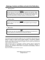
Warnings, Cautions and Notes as Used in this Publication
1. Warning notice:
WARNING
Warning notices are used in this publication to emphasize that hazardous voltages,
currents, temperatures, or other conditions that could cause personal injury exist in
this equipment or may be associated with its use. In situations where inattention could
cause either personal injury or damage to equipment, a warning notice is used.
2. Caution notice:
CAUTION
Caution notices are used in this publication where equipment might be damaged if
care is not taken.
3. Note notice:
NOTE
Note notices are used in this publication merely call attention to information that is
especially significant to understanding and operating the equipment.
This document is based on information available at the time of its publication. While efforts have been
made to be accurate, the information contained herein does not purport to cover all details or variations in
hardware or software, nor provide for every possible contingency in connection with installation,
operation, or maintenance. Features may be described herein which are not present in all hardware and
software systems. FANUC FA America assumes no obligation of notice to holders of this document with
respect to changes subsequently made.
FANUC FA America makes no representation or warranty, expressed, implied, or statutory with
respect to, and assumes no responsibility for the accuracy, completeness, sufficiency, or
usefulness of the information contained herein. No warranties of merchantability or fitness for
purpose shall apply.
No part of this manual may be reproduced in any form.
© 2013 FANUC FA America Corporation
All Rights Reserved
This page intentionally left blank.
FASOPC Server – User’s Manual
FANUC FA America
Table of Contents
1 General ...................................................................................................................... 1
1.1 Introduction to FASOPC Server ......................................................................................................2
1.2 CNC Requirements .........................................................................................................................3
1.2.1 Models Supported ............................................................................................................................... 3
1.2.2 Required Options ................................................................................................................................ 4
1.2.3 Additional Options ............................................................................................................................... 4
1.3 Supported Functions .......................................................................................................................5
1.3.1 System Data Access ........................................................................................................................... 5
1.4 PC Requirements ............................................................................................................................5
1.4.1 Hardware ............................................................................................................................................ 5
1.4.2 Software .............................................................................................................................................. 5
2 System Setup ............................................................................................................. 7
2.1 Installation .......................................................................................................................................8
2.1.1 Provided Hardware ............................................................................................................................. 8
2.1.2 Software Installation ............................................................................................................................ 8
2.1.3 License Installation............................................................................................................................ 12
2.2 System Confirmation .....................................................................................................................15
2.2.1
2.2.2
2.2.3
2.2.4
Confirm CNC Connection .................................................................................................................. 15
Confirm UI Operation ........................................................................................................................ 16
Confirm Server Connection ............................................................................................................... 23
Confirm Local Client Access ............................................................................................................. 25
3 FASOPC Configurator .............................................................................................. 29
3.1 OPC Explorer ................................................................................................................................31
3.1.1
3.1.2
3.1.3
3.1.4
3.1.5
Add Element ................................................................................................................................. 31
Delete Element
............................................................................................................................ 31
Refresh
....................................................................................................................................... 31
Expand Tree
............................................................................................................................... 31
Collapse Tree
.............................................................................................................................. 31
3.2 Property View
.........................................................................................................................32
3.2.1 Next Button
.................................................................................................................................. 32
3.2.2 Previous Button
........................................................................................................................... 32
3.3 Data View ......................................................................................................................................33
3.4 Server Status ................................................................................................................................34
3.5 Configuration Settings ...................................................................................................................36
3.5.1
3.5.2
3.5.3
3.5.4
3.5.5
3.5.6
3.5.7
3.5.8
Minimum Client Update Time ............................................................................................................ 36
Device Update Rate .......................................................................................................................... 36
Read Write Device Timeout .............................................................................................................. 36
Log File Open Time........................................................................................................................... 37
Log File Maximum Lifetime ............................................................................................................... 37
Log File Level .................................................................................................................................... 37
Security Private ................................................................................................................................. 37
Shutdown When Last Client Disconnects ......................................................................................... 37
3.6 Machine Configuration Wizard ......................................................................................................37
3.7 Point Configuration Wizard ...........................................................................................................40
3.7.1
3.7.2
3.7.3
3.7.4
3.7.5
CNC Position Point ........................................................................................................................... 40
CNC Program Number ...................................................................................................................... 43
CNC Alarms ...................................................................................................................................... 45
CNC System Data ............................................................................................................................. 47
CNC Macro Variables ....................................................................................................................... 49
D74C-0405-PB01/01
www.fanucfa.com
Page i
FASOPC Server – User’s Manual
FANUC FA America
3.7.6 CNC Offset Memory A ...................................................................................................................... 51
3.7.7 CNC Offset Memory B ...................................................................................................................... 54
3.7.8 CNC Offset Memory C ...................................................................................................................... 57
3.7.9 PMC Bit Point .................................................................................................................................... 60
3.7.10 PMC Byte Point ................................................................................................................................. 63
3.7.11 PMC 2Byte Point ............................................................................................................................... 65
3.8 Load New Server Configuration ....................................................................................................67
3.8.1 Save Configuration File ..................................................................................................................... 67
3.8.2 Restart the Server ............................................................................................................................. 67
3.8.3 Connect to Server from FASOPC Configurator ................................................................................. 68
4 FASOPC Server ....................................................................................................... 71
4.1 Statistics View ...............................................................................................................................72
4.1.1
4.1.2
4.1.3
4.1.4
4.1.5
4.1.6
4.1.7
4.1.8
Sample Period................................................................................................................................... 72
Number of Clients ............................................................................................................................. 72
Number of Groups............................................................................................................................. 72
Number of Items................................................................................................................................ 72
Number of Read Operations ............................................................................................................. 73
Number of Write Operations ............................................................................................................. 73
Number of Values Changed .............................................................................................................. 73
License Expirations ........................................................................................................................... 73
4.2 Trace Messages ............................................................................................................................73
4.2.1
4.2.2
4.2.3
4.2.4
Log File Settings ............................................................................................................................... 74
Log File Open Time........................................................................................................................... 74
Log File Maximum Lifetime ............................................................................................................... 74
Log File Level .................................................................................................................................... 74
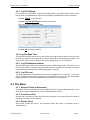
4.3 File Menu ......................................................................................................................................74
4.3.1 Request Clients to Disconnect .......................................................................................................... 74
4.3.2 Force Server Exit .............................................................................................................................. 74
4.3.3 Restart Server ................................................................................................................................... 74
4.4 Help Menu .....................................................................................................................................75
5 Troubleshooting ....................................................................................................... 77
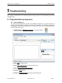
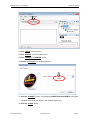
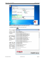
5.1 Expected Start-up Sequence ........................................................................................................78
5.1.1 Server Start-up .................................................................................................................................. 78
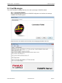
5.2 Fault Messages .............................................................................................................................81
5.2.1 Connection Failed ............................................................................................................................. 81
Appendix A – Revision History ..................................................................................... 84
D74C-0405-PB01/01
www.fanucfa.com
Page ii
FASOPC Server – User’s Manual
FANUC FA America
1 General
D74C-0405-PB01/01
www.fanucfa.com
Page 1
FASOPC Server – User’s Manual
FANUC FA America
1 General
This chapter provides general information about the intention, capabilities, and pre-requisites of the
FASOPC Server system.
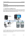
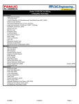
1.1 Introduction to FASOPC Server
The FASOPC Server was developed by FANUC FA America to provide access to data within FANUC
CNCs and translate it into the standard OPC format. This translated server data exposes an OPC
interface to multiple OPC clients through the Ethernet connection. This software package runs on a
Windows® based computer to provide access to FANUC CNC data on the factory floor. FASOPC
software is compliant with OPC data access standards 3.0, 2.0, and 1.0a.
FASOPC SERVER
CLIENT #1
(SAP SERVER)
OPC READ/WRITE DATA
FOCAS READ/WRITE DATA
ETHERNET
CLIENT #2
(PLC)
CLIENT #3
(Wireless PC)
CNC #1
CNC #2
The FASOPC Configurator software is an intuitive user interface which provides a database driven
collection of configuration wizards making it easy to setup the server and machine connections.
Additionally to configure machine data, a point wizard guides you through the setup of data collection by
specifying the machine, path, and point selections.
D74C-0405-PB01/01
www.fanucfa.com
Page 2
FASOPC Server – User’s Manual
FANUC FA America
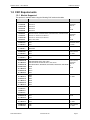
1.2 CNC Requirements
1.2.1 Models Supported
This product is available when using the following CNC series and models.
SERIES
SOFTWARE MINIMUM
CONNECTION
30i-Model B
G301/G311/G321/G331
Ethernet Board,
31i-Model B
G401/G411
31i-Model B5
G421/G431
Embedded
Ethernet,
32i-Model B
G501/G511
35i-Model B
G601/G611
30i-Model A
G001/G011/G021, G002/G012/G022, G003/G013/G023, G004/G014/G024
31i-Model A
G101/G111, G103/G113, G104/G114
Embedded
Ethernet,
31i-Model A5
G121/G131, G123/G133, G124/G134
or
32i-Model A
G201, G203, G204
HSSB
0i-M Model D
D4F1
Embedded, Board,
0i-T Model D
D6F1
or HSSB
0i-M Model C
D4B1
Ethernet Board
0i-T Model C
D6B1/D6D1
0i-M Model B
D4A1
Ethernet Board,
0i-T Model B
D6A1
or HSSB
0i-M Model A
D401
HSSB
0i-T Model A
D601
or
HSSB
Ethernet Board,
16i-M Model B
B0H1/B0HA/B0HK, B0K1, B0N1, B0M1
Ethernet Board,
16i-T Model B
B1H1/B1HA/B1HK, B1D4/B1D6, B1K1, B1N1, B1M1
18i-M Model B
BDH1/BDHA/BDHK, BDH5/BDHE, BDK1/BDK5, BDN1/BDN5, BDM1/BDM5
Embedded
Ethernet,
18i-M Model B5
BDHE
18i-T Model B
BEH1
21i-M Model B
DDHA
21i-T Model B
DEK1
16i-M Model A
B0FA
Ethernet Board,
16i-T Model A
B1D5
or HSSB
18i-M Model A
BDF4
18i-T Model A
BEFB
21i-M Model A
BH00
21i-T Model A
DEF4
16-M Model C
A0DA
HSSB
15i-M Model B
F0A3
HSSB
15i-T Model B
F6A2
15i-M Model A
F004
Ethernet Board,
15i-T Model A
F005
or HSSB
15-M Model B
A0B1
Ethernet Board,
15-T Model B
A2D1
or HSSB
or
HSSB
16-T Model C
18-M Model C
18-T Model C
D74C-0405-PB01/01
www.fanucfa.com
Page 3
FASOPC Server – User’s Manual
FANUC FA America
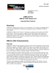
1.2.2 Required Options
The table below shows CNCs that require options to allow FASOPC server access to the CNC
data. Either the HSSB or Ethernet option will fulfill the requirement.
SERIES
DESCRIPTION
OPTION
15i Model A
Ethernet Function FOCAS1 + Extended Drivers and Libraries
A02B-0207-J647 + J801
15i Model B
HSSB Extended Drivers and Libraries
A02B-0207-J801
Ethernet Function FOCAS1 + Extended Drivers and Libraries
A02B-0207-S707 + J800
HSSB Extended Drivers and Libraries
A02B-0207-J800
Ethernet Function FOCAS1 + Extended Drivers and Libraries
A02B-0259-J862 + J847
HSSB Extended Drivers and Libraries
A02B-0259-J847
Ethernet Function FOCAS1 + Extended Drivers and Libraries
A02B-0207-S707 + J800
HSSB Extended Drivers and Libraries
A02B-0207-J800
0i Model A
HSSB Extended Drivers and Libraries
A02B-0207-J800
16/18 Model C
HSSB Extended Drivers and Libraries
A02B-0207-J800
15 Model B
HSSB Extended Drivers and Libraries
A02B-0207-J801
16i/18i/21i Model A
PowerMate-i
0i Model B
The controllers listed below are available with an embedded Ethernet port on the main board.
If the embedded Ethernet port is not installed, one of the following options is required.
Ethernet Function
A02B-0207-S707
HSSB Extended Drivers and Libraries
A02B-0207-J800
Ethernet Function
A02B-0308-S707
HSSB Extended Drivers and Libraries
A02B-0207-J900
0i Model C
Ethernet Function
A02B-0310-S707
0i Model D
HSSB Extended Drivers and Libraries
A02B-0207-J800
21i Model B
32i Model A
1.2.3 Additional Options
The 30i/31i/16iB/18iB controllers have an embedded Ethernet port on the CNC MAIN board. This
port may be used by FASOPC software; however greater performance may be realized utilizing
the Ethernet option board or HSSB option board fiber optic interface.
SERIES
DESCRIPTION
OPTION
30i/31i/32i Model A
Ethernet Function
A02B-0207-J647
30i/31i/32i Model B
HSSB Extended Drivers and Libraries
A02B-0207-J801
16i/18i/21i Model B
Ethernet Function
A02B-0207-S707
HSSB Extended Drivers and Libraries
A02B-0207-J800
D74C-0405-PB01/01
www.fanucfa.com
Page 4
FASOPC Server – User’s Manual
FANUC FA America
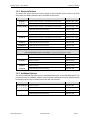
1.3 Supported Functions
This section details the functions provided by the FASOPC Server.
1.3.1 System Data Access
This product supports access to the following system data types.
TYPE
DESCRIPTION
CNC
Control System Information – model, type, and path count
CNC
Tool Offset – geometry, wear, tool life, tool management
RW
CNC
Work Offset – offset data, work shift, and extended work offsets
RW
CNC
Program Data – main program and active program numbers
CNC
Macro Variables – common and local variable (read/write)
CNC
Alarm Numbers and Messages – active CNC alarms
R
SERVO
Position Data = absolute, relative, machine, and distance to go
R
SERVO
Axis Info – axis names and axis count
R
PMC
SERVER
READ/WRITE
R
R
RW
RW
PMC Data – X,Y,G,F,R,D,A,C,T,K, (read/write)
Real-time server statistics
R
1.4 PC Requirements
This section details the minimum PC requirements for this software product.
1.4.1 Hardware
The following list details the appropriate hardware environment for the software.
ITEM
MINIMUM
RECOMMENDED
PROCESSOR
Single-core processor, 1.6Ghz
Quad-core processor, 2.8Ghz
RAM
1GB of working RAM memory
4GB of working RAM memory
HARD DISK
100Mb of free hard disk space
100Mb of free hard disk space
NETWORK
100base-T Ethernet adapter
100base-T Ethernet adapter
PCI SLOT
PCI slot is used if HSSB is used (fiber optic)
PCI slot is used if HSSB is used (fiber optic)
1024 x 768 SVGA video display resolution
1280 x 1024 XGA video display resolution
VIDEO
1.4.2 Software
This software will perform utilizing the following PC operating systems and support files.
ITEM
DESCRIPTION
OS
Windows 7 Professional 32bit or 64bit
OS
Windows XP Professional 32bit
OS
Windows 2008 Server R2 64bit
.NET
Microsoft ,NET Framework 4.0 Client
.NET
Microsoft .NET Framework 4.0 Extended
D74C-0405-PB01/01
www.fanucfa.com
Page 5
FASOPC Server – User’s Manual
FANUC FA America
This page intentionally left blank.
D74C-0405-PB01/01
www.fanucfa.com
Page 6
FASOPC Server – User’s Manual
FANUC FA America
2 System Setup
D74C-0405-PB01/01
www.fanucfa.com
Page 7
FASOPC Server – User’s Manual
FANUC FA America
2 System Setup
This chapter details the FASOPC Server software installation, basic setup, and confirmation.
2.1 Installation
This section details the steps of software installation for the Windows 7 operating system. Installation with
Windows XP is almost identical. You must be computer ADMINISTRATOR to perform this operation.
2.1.1 Provided Hardware
A DVD-ROM disk of the FASOPC Server software and a USB licensing key are provided.
ITEM
DESCRIPTION
DVD ROM
D72F-0405-PB00 – Software with activation key.
Provides unlimited* clients and 1 CNC connection.
* determined by number of CNC points and PC performance.
USB license key
D72F-0405-PQ02 – 10 additional CNC connections
D72F-0405-PQ03 – 20 additional CNC connections
D72F-0405-PQ04 – 30 additional CNC connections
D72F-0405-PQ05 – 40 additional CNC connections
D72F-0405-PQ06 – 50 additional CNC connections
D72F-0405-PQ07 – 100 additional CNC connections
2.1.2 Software Installation
This section details the installation of the FASOPC Server software. The standard installation
installs both the FASOPC Server and the FASOPC Configurator. If you select the CUSTOM
installation it is possible to choose installation of either component individually.
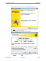
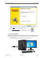
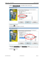
1) Insert the DVD-ROM into the PC. The InstallShield wizard will automatically start.
D74C-0405-PB01/01
www.fanucfa.com
Page 8
FASOPC Server – User’s Manual
FANUC FA America
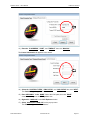
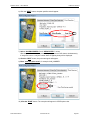
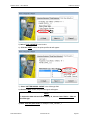
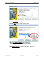
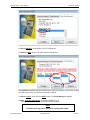
The install shield wizard will confirm you are installing FASOPC software.
2) Click “NEXT“ to continue the installation.
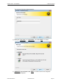
The license agreement window appears. Read the agreement.
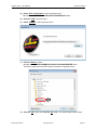
3) Click “I ACCEPT“ then click “NEXT“ to continue the installation.
D74C-0405-PB01/01
www.fanucfa.com
Page 9
FASOPC Server – User’s Manual
FANUC FA America
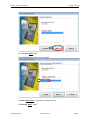
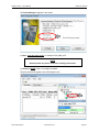
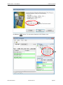
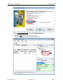
The customer information window appears…
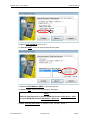
4) Enter your “user name“ and “organization”, then click “NEXT“ to continue.
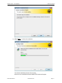
5) COMPLETE is pre-selected, click “NEXT“ to install the server and configurator.
Ready to install appears…
D74C-0405-PB01/01
www.fanucfa.com
Page 10
FASOPC Server – User’s Manual
FANUC FA America
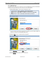
6) Click “NEXT“ to continue the installation.
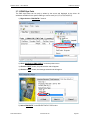
The software installation will take a few minutes…
When done, the InstallShield Wizard COMPLETED window will appear.
D74C-0405-PB01/01
www.fanucfa.com
Page 11
FASOPC Server – User’s Manual
FANUC FA America
7) Click “FINISH“ button to complete the installation.
8) The “FASOPC Configurator” icon will appear on the desktop.
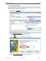
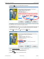
2.1.3 License Installation
Once installed, the software will run in demo mode for 30 days. A USB license key may be
purchased to license this software indefinitely. Follow these instructions to install the license.
1) Insert the USB key into the PC that will act as the FASOPC server.
D74C-0405-PB01/01
www.fanucfa.com
Page 12
FASOPC Server – User’s Manual
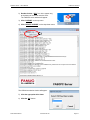
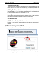
FANUC FA America
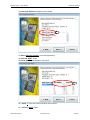
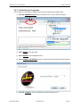
2) Double-click the “OPC” icon in the system tray,
at the bottom of the screen near the clock.
The FASOPC server window will appear.
3) Click “LICENSE“ on the top menu.
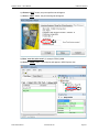
4) Click “UPDATE LICENSE“ on the drop-down menu.
The USB drive selection window will appear.
5) Click the appropriate drive letter.
6) Click the “OK“ button.
D74C-0405-PB01/01
www.fanucfa.com
Page 13
FASOPC Server – User’s Manual
FANUC FA America
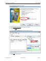
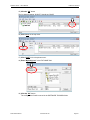
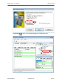
The LICENSE UPGRADE window will appear.
On the left side of this window the current license information is shown, on the right side are
the details of the new license that will be accepted when the COMMIT button is clicked.
7) Click the “COMMIT“ button to accept the new licensing values.
The confirmation window will appear.
8) Click the “OK“ button to complete the licensing process.
The FASOPC server will shut down and the new licensing will take affect the next time the
server is started. The server will restart if a client requests data or it may be restarted in the
FASOPC configurator software.
D74C-0405-PB01/01
www.fanucfa.com
Page 14
FASOPC Server – User’s Manual
FANUC FA America
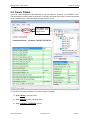
2.2 System Confirmation
The operation of the user interface must be performed as computer Administrator.
2.2.1 Confirm CNC Connection
This procedure confirms the network connection between the CNC and the FASOPC server. In
this example the OPC Server has an IP address of 192.168.5.50 and the CNC that is being
confirmed has an IP address of 192.168.5.100. This example assumes a 30i Model A control unit.
Operation may be slightly different on other control series or models.
1) Press the
button
on the MDI key pad.
2) Press the
soft key
to change the menu.
3) Choose
or
key.
The EMBED PORT is on the CNC main board.
The ETHER BOARD is an option board.
4) Confirm the IP ADDRESS is 192.168.5.100
and the SUBNET MASK is 255.255.255.0
5) Press the
soft key on the CNC
menu. Confirm the PORT NUMBER (TCP) is 8193.
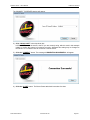
On the PC…
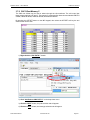
6) Choose START -> PROGRAMS -> ACCESSORIES -> COMMAND PROMPT
The command prompt window will appear.
7) Type “PING 192.168.5.100” then press “ENTER“ on the keyboard.
The connection will be tested four times. “REPLY FROM” indicates a good connection.
REPLY FROM = GOOD
D74C-0405-PB01/01
www.fanucfa.com
Page 15
FASOPC Server – User’s Manual
FANUC FA America
The integrity of the connection is tested four times. If the “REPLY FROM“ response is not
received, confirm the network switch/hub is connected appropriately and the IP addresses of the
FASOPC server and CNC are correct.
2.2.2 Confirm UI Operation
This section focuses on the basic setup and operation of the FASOPC software. More details are
provided in later sections of this manual.
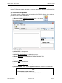
1) Double-Click the “FASOPC Configurator” icon on the desktop.
The user interface will open.
2) Click “FILE“ on the top menu.
3) Click “New Configuration“ on the drop-down menu.
4) Enter “MyConfig1” in the ENTER CONFIGURATION NAME field.
5) Click the “DONE” button.
6) Click “FILE” on the top menu.
7) Select “Save Configuration” on the drop-down menu.
8) Click the “SAVE” button. The file ‘myconfig1.fs2’ will be created in the default folder.
NOTE
The default save folder location is…
C:\PROGRAMDATA\FANUCFAS\FASOPCUI
D74C-0405-PB01/01
www.fanucfa.com
Page 16
FASOPC Server – User’s Manual
FANUC FA America
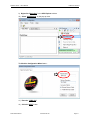
9) Right-click “MyConfig1” in the OPC Explorer window.
10) Select “Add Machine” on the pop-up menu.
The Machine Configuration Wizard starts…
11) Enter the “16iMA-100”
12) Click the “NEXT” button.
D74C-0405-PB01/01
www.fanucfa.com
Page 17
FASOPC Server – User’s Manual
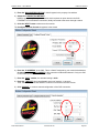
FANUC FA America
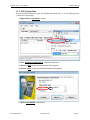
13) Enter the “IP ADDRESS”, “PORT”, and “TIMEOUT” then click “MANUAL”.
The Control Information tab appears in the wizard.
14) Select the “CONTROL TYPES”, “PMC PATHS”, and “CNC PATHS” then click “NEXT”.
The Path Naming tab appears in the wizard.
15) Enter “MEGAMILL” in the “NAME” field of this CNC path, then click “DONE”.
A machine now appears in OPC Explorer view.
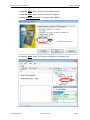
16) Right-click “16iMA-100” in the OPC Explorer window.
17) Select “Add Point to 16iMA-100” on the pop-up menu.
The Point Configuration Wizard starts…
D74C-0405-PB01/01
www.fanucfa.com
Page 18
FASOPC Server – User’s Manual
FANUC FA America
18) Click the “NEXT” button.
The PATH Selection tab appears in the wizard.
19) Select “CNC Path 1” in the path for data point list box.
20) Click the “NEXT” button. .
D74C-0405-PB01/01
www.fanucfa.com
Page 19
FASOPC Server – User’s Manual
FANUC FA America
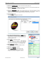
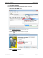
The Data Type Selection tab appears in the wizard.
21) Select “Absolute Position” in the data type list box,
22) Click the “NEXT” button.
The Point Specifics tab appears in the wizard.
23) Select “1” in the axis number and array size list boxes,
24) Click the “NEXT” button.
D74C-0405-PB01/01
www.fanucfa.com
Page 20
FASOPC Server – User’s Manual
FANUC FA America
The Point Naming tab appears in the wizard.
25) Enter “enter the point name”, for example: POS_ABS_X.
26) Click the “DONE” button.
A point now appears in OPC Explorer under the machine 16iMA-100
27) Click “FILE” on the top menu.
D74C-0405-PB01/01
www.fanucfa.com
Page 21
FASOPC Server – User’s Manual
FANUC FA America
28) Select “Save Configuration” on the drop-down menu.
This saves to ‘C:\PROGRAMDATA\FANUCFAS\FASOPCUI folder.
29) Click the “FILE” on the top menu.
30) Select “EXPORT” on the drop-down menu.
31) Click the “Browse” button.
Navigate to the ‘C:\PROGRAMDATA\FANUCFAS\FASOPCSERVER folder.
This is the location where the OPC Server will load it’s configuration from.
32) Click the “OK” button, then click the “OK” button. The export dialog window closes.
D74C-0405-PB01/01
www.fanucfa.com
Page 22
FASOPC Server – User’s Manual
FANUC FA America
2.2.3 Confirm Server Connection
The next step is to confirm the FASOPC Server will start. Follow the procedure below.
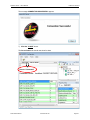
1) Click the “SERVER STATUS” tab next to Data View. The user interface will open.
2) Click “TOOLS” on the top menu.
3) Click “SERVER” on the drop-down menu.
4) Click “CONNECT TO SERVER” choice. Local Host is pre-selected in the drop-down box.
5) Click the “CONNECT” button to establish connection with the server.
D74C-0405-PB01/01
www.fanucfa.com
Page 23
FASOPC Server – User’s Manual
FANUC FA America
The message CONNECTION SUCCESSFUL appears.
7) Click the “CLOSE” button.
The Server Status tab should now show live data.
D74C-0405-PB01/01
www.fanucfa.com
Page 24
FASOPC Server – User’s Manual
FANUC FA America
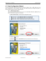
2.2.4 Confirm Local Client Access
This section details local client access to the FASOPC Server. In this example the Software
Toolbox OPC Quick Client freeware is explained.
1) Double-Click the “OPC QUICK CLIENT” icon on the desktop.
The user interface will open.
2) Click “EDIT” on the top menu.
3) Click “NEW SERVER CONNECTION” on the drop-down menu.
4) Under “LOCAL MACHINE” click on FASOPC.SERVER.0.
5) Click the “OK” button.
6) Click “EDIT” on the top menu.
7) Click “NEW GROUP” on the drop-down menu
D74C-0405-PB01/01
www.fanucfa.com
Page 25
FASOPC Server – User’s Manual
FANUC FA America
8) Enter “16iMA-100” in the NAME field.
9) Click the “OK” button.
10) Click “EDIT” on the top menu.
11) Click “NEW ITEM” on the drop-down menu.
12) Under FASOPC.SERVER.0 click on “16iMA-100.”
13) Click “POS ABS X” in the leaf browsing field.
14) Click the “ADD LEAVES” button.
D74C-0405-PB01/01
www.fanucfa.com
Page 26
FASOPC Server – User’s Manual
FANUC FA America
15) Click the “OK” button
The live data will appear, QUALITY should say GOOD.
16) Click “FILE” on the top menu.
17) Click “SAVE” on the drop-down menu.
18) Enter “MyConfig1.otc” in the FILE NAME field.
19) Click the “OK” button.
The configuration file will be saved in the SOFTWARE TOOLBOX folder.
D74C-0405-PB01/01
www.fanucfa.com
Page 27
FASOPC Server – User’s Manual
FANUC FA America
This page intentionally left blank.
D74C-0405-PB01/01
www.fanucfa.com
Page 28
FASOPC Server – User’s Manual
FANUC FA America
3 FASOPC Configurator
D74C-0405-PB01/01
www.fanucfa.com
Page 29
FASOPC Server – User’s Manual
FANUC FA America
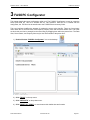
3 FASOPC Configurator
This chapter details the server configuration editor tool. The FASOPC Configurator is used to create the
server point data file. This file is created with an .FS2 extension. After the file is created with the
configurator, the .FS2 file must be transferred to the FASOPCServer directory folder.
This user interface simplifies the process of creating the server point data file. There are four primary
views within the UI, the Data view, OPC Explorer, Property view, and the Server Status view. The views
are dock able and can be arranged to the users liking by dragging them within the parent form. The Data
View, Server Status, and Property View may be also float outside of the parent form.
1) Double-Click the “FASOPC Configurator” icon on the desktop.
2) Click “TOOLS” on the top menu.
3) Click “DEFAULTS” on drop-down menu.
4) Click “RESET ALL VIEWS”, to reset views to their default size and location.
D74C-0405-PB01/01
www.fanucfa.com
Page 30
FASOPC Server – User’s Manual
FANUC FA America
3.1 OPC Explorer
The explorer view provides a tree view of the configured machines and points. This is where changes to
the configuration are initiated. The tool bar at the top of the window or the menu at the top of the parent
window may be used.
The hierarchy of this display is CONFIG MACHINE PATH POINT.
3.1.1 Add Element
The function of this toolbar button is
dependent on what is currently selected in
the window. When the window is blank the
system will assume you want to create a
new configuration. If the configuration is
currently selected, the system assumes you
want add a new machine. If a machine is
selected, the system assumes you want to
add a new point for that machine.
NOTE
Decimal points may not be used
when creating element names.
3.1.2 Delete Element
What will be deleted by this toolbar button
is dependent on what is currently selected
in the window. MACHINEs, PATHs, and
POINTs
may
be
deleted.
Entire
configurations may not. To delete a point,
click the point to highlight it, then click the
delete element tool button. A confirmation
window will appear before it is actually
deleted.
3.1.3 Refresh
This button initiates a manual refresh of the
OPC Explorer view. If a new element has
been added the view will automatically
refresh.
3.1.4 Expand Tree
This button fully expands the tree view to
expose all machines, paths, and point
currently configured in the active server
configuration. Clicking the
button to the left of any element will expand the tree to reveal all of
the related sub-elements.
3.1.5 Collapse Tree
This button fully collapses the tree view to expose only the root configuration. Clicking the
button to the left of any element will collapse only of the relative sub-elements.
D74C-0405-PB01/01
www.fanucfa.com
Page 31
FASOPC Server – User’s Manual
FANUC FA America
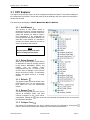
3.2 Property View
This window shows detail about the element that is currently selected in the OPC Explorer view.
Property View details the
element selected in the
OPC Explorer view.
3.2.1 Next Button
The NEXT button advances to the next item in the OPC Explorer view relative to the currently
selected item. The details of the selected element are displayed in the Property View.
3.2.2 Previous Button
The PREVIOUS button advances to the previous item in the OPC Explorer view relative to the
currently selected item. The details of the element are displayed in the Property View.
D74C-0405-PB01/01
www.fanucfa.com
Page 32
FASOPC Server – User’s Manual
FANUC FA America
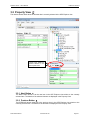
3.3 Data View
This window displays detail of the configured points under the configuration, CNC node, CNC Path, or
PMC path. Double-click the nodes to view the details of the configured sub-elements.
If the data view is not visible…
1) Click “VIEWS” on the top menu.
2) Click the “DATA VIEW” choice.
D74C-0405-PB01/01
www.fanucfa.com
Page 33
FASOPC Server – User’s Manual
FANUC FA America
3.4 Server Status
The server status window provides information to the user about the operation of the FASOPC server.
This information includes whether Configurator is currently connected to the server, licensing information
for the FASOPC server, and status flag information from the server.
Server Status details
the connection of the
FASOPC Server.
To view the server status information, the server must be connected.
1) Click “TOOLS” on the top menu.
2) Click “SERVER” on the drop-down menu.
3) Click “CONNECT TO SERVER” choice.
D74C-0405-PB01/01
www.fanucfa.com
Page 34
FASOPC Server – User’s Manual
FANUC FA America
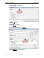
The CONNECT TO SERVER window will appear.
4) Click “LOCAL HOST” in the drop-down box.
LOCAL HOST means the server is the PC you are currently using, which is used in this example
initially to confirm the system is functioning correctly. Afterward this setting may be changed to
the server’s IP or network name to connect to a remote server.
5) Click the “CONNECT” button. The message ‘CONNECTION SUCCESSFUL’ will appear.
6) Click the “CLOSE” button. The Server Status tab should now show live data.
D74C-0405-PB01/01
www.fanucfa.com
Page 35
FASOPC Server – User’s Manual
FANUC FA America
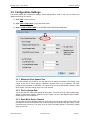
3.5 Configuration Settings
This section details the configuration settings. These settings will be used be the server to control the
update rate and log file creation.
1) Click “FILE” on the top menu.
2) Click “New Configuration” on the drop-down menu.
3) Enter <YOUR CONFIG NAME> in the ENTER CONFIGURATION NAME field.
3.5.1 Minimum Client Update Time
The client software you choose to use will also have an update time setting. This setting is the
master of the two, so if this setting is 1000mSec and the client is set to 100mSec, the client
setting will be overridden to 1000mSec. This value is set in units of milliseconds; default is 1000
which equals 1 second. Setting range is 0~2,147,483,647.
3.5.2 Device Update Rate
This is how often the CNC will be polled for information. This value is set in units of milliseconds;
default is 1000 which equals 1 second. For best results, use the CNC Ethernet option boards.
Setting range is 0~2,147,483,647.
3.5.3 Read Write Device Timeout
This sets the maximum allowable time from when the server sends the request to the CNC until
the response returns back from the CNC. If the round-trip time is greater than this setting, a CNC
connection time-out occurs. This value is set in units of seconds, default is 10 seconds. Setting
range is 0~32,767.
D74C-0405-PB01/01
www.fanucfa.com
Page 36
FASOPC Server – User’s Manual
FANUC FA America
3.5.4 Log File Open Time
This sets the maximum amount of time the current server log file will be used. At the end of this
period a new log file will be created and the old file will remain in the LOGS directory folder. This
value is set in units of minute, default is 90 minutes. Setting range is 0~2,147,483,647.
3.5.5 Log File Maximum Lifetime
This sets how long the log file will remain in the server LOGS directory folder. This value is set in
units of days, default is 14 days. Any log files that remain in the folder for more than 14 days will
be automatically deleted from the folder. Setting range is 0~32,767.
3.5.6 Log File Level
This setting determines how detailed the server log messages will be. Log level 1 is the least
amount of logging and is used for typical day to day operations. Log level 5 is the most detailed
logging level and is used when troubleshooting a connection or server problem.
3.5.7 Security Private
This checkbox enables OPC server connection security. Default setting is OFF.
3.5.8 Shutdown When Last Client Disconnects
This checkbox flags the FASOPC server to shut down when it detects no clients are connected.
Regardless of this setting, the server will automatically start when any client requests a
connection.
3.6 Machine Configuration Wizard
This wizard steps through the process of adding a new machine to the configuration file.
1) There are three ways to invoke the machine configuration wizard…
On main menu – TOOLS WIZARDS MACHINE CONFIGURATION
Explorer View – RIGHT-CLICK configuration and select ADD MACHINE
Explorer View – CLICK + toolbar button with the configuration pre-selected
2) Enter the “MACHINE NAME”, which can be any name the user wants. This will be the primary
node name displayed in explorer view.
D74C-0405-PB01/01
www.fanucfa.com
Page 37
FASOPC Server – User’s Manual
FANUC FA America
3) Enter the “MACHINE DESCRIPTION”, this will appear in the property view window.
4) Select the “CONNECTION METHOD”.
HSSB is a proprietary fiber optic connection which requires an option board in the CNC.
ETHERNET is a local network connection, ideally connected to the server through a switch.
5) Click the “NEXT” button to advance to the next tab.
The Configure Ethernet Control tab appears in the wizard.
6) Enter the “IP ADDRESS” of the CNC. This is a fixed IP assigned by your network administrator.
Or enter the HSSB “NODE NUMBER” if this connection method was selected. If only one CNC
is connected by HSSB, node number 0 is used.
7) Enter the “PORT” number, the standard setting is 8193.
8) Enter the “TIMEOUT” this is the allowable amount of inactivity, in seconds.
TEST CONNECTION and AUTOMATIC mode do not function in this beta version.
9) Click “MANUAL” to continue manual configuration of the CNC connection.
D74C-0405-PB01/01
www.fanucfa.com
Page 38
FASOPC Server – User’s Manual
FANUC FA America
10) Select the “CONTROL TYPE”, series and model in the drop-down box.
11) Select the “PMC PATHS” number, most controls only have one. The 30i series controllers have
options for three or up to five individual PMC ladders.
12) Select the “CNC PATHS” number, most controls only have one. This is the number of G-code
programs the control is capable of processing simultaneously. The 30i series controls are
capable of up to ten simultaneous paths; older series may have up to three paths.
13) Click the “NEXT” button.
The Path Naming tab appears in the wizard.
14) Enter MACHINE DESIGNATOR in the “NAME” field of
this CNC path. This name will appear to the right of the
CNC path node in parenthesis. The description text will
appears in property view.
15) Click “DONE” to complete the wizard.
The added machine now appears in OPC Explorer
view, and if selected by a mouse click the details that
have just been entered appear in the Property View.
16) Click “16iMA-100” in explorer.
Notice the property view shows the details entered.
17) Right-Click “16iMA-100” in explorer.
18) Select “EDIT 16iMA-100” on the pop-up menu.
This will start the wizard again so you can make
changes to the machine configuration if desired.
D74C-0405-PB01/01
www.fanucfa.com
Page 39
FASOPC Server – User’s Manual
FANUC FA America
3.7 Point Configuration Wizard
The point configuration wizard steps through the process of adding a CNC or PMC data point to the
server configuration file. After choosing a point type, the wizard will step you through the process of
entering all the properties required to define that point.
3.7.1 CNC Position Point
The CNC position data can be read by the server. The MACHINE, RELATIVE, ABSOLUTE, and
DIST TO GO position registers are accessible.
1) There are three ways to invoke the point configuration wizard…
On main menu – TOOLS WIZARDS POINT CONFIGURATION
Explorer View – RIGHT-CLICK CNC Path1 and select ADD POINT
Explorer View – CLICK + toolbar button with the machine pre-selected
2) Click the “NEXT” button.
3) Click the “NEXT” button, CNC PATH1 should be preselected in the PATH list box.
D74C-0405-PB01/01
www.fanucfa.com
Page 40
FASOPC Server – User’s Manual
FANUC FA America
4) Select “ABSOLUTE POSITION” in the SELECT DATA TYPE list box.
5) Click the “NEXT” button.
The Point Specifics tab appears in the wizard.
6) Select the “AXIS NUMBER=1” and “ARRAY SIZE=3” values.
The array size lets you view several axis absolute positions by using only one data point.
7) Click the “NEXT” button.
D74C-0405-PB01/01
www.fanucfa.com
Page 41
FASOPC Server – User’s Manual
FANUC FA America
The Point Naming tab appears in the wizard.
8) Enter “enter the point name”, for example: POS_ABS_XYZ.
NOTE
Decimal points may not be used when creating point names.
9) Click the “DONE” button, to complete the wizard.
The point should now appear in the OPC Explorer view.
D74C-0405-PB01/01
www.fanucfa.com
Page 42
FASOPC Server – User’s Manual
FANUC FA America
3.7.2 CNC Program Number
The main program and current program may be configured as read points. The MAIN program is
the primary program being executed. The CURRENT program is the sub-program that is currently
executing which was called from the MAIN program.
1) Right-click the “CNC PATH 1” branch.
2) Click “Add Point to CNC PATH 1” on the drop-down menu.
3) Click the “NEXT” button, the path selection tab will appear.
4) Click the “NEXT” button, the data type selection tab will appear.
5) Select “MAIN PROGRAM NUMBER” in the data type list box.
D74C-0405-PB01/01
www.fanucfa.com
Page 43
FASOPC Server – User’s Manual
FANUC FA America
6) Click the “NEXT” button, the point specifics tab will appear.
7) Click the “NEXT” button, the point naming tab will appear.
8) Enter “enter the point name”, for example: PROG_MAIN.
9) Click the “DONE” button. The new point will appear in OPC Explorer view.
D74C-0405-PB01/01
www.fanucfa.com
Page 44
FASOPC Server – User’s Manual
FANUC FA America
3.7.3 CNC Alarms
The CNC alarm numbers and messages may be read as points. An array of messages may also
be selected to read multiple messages if desired.
1) Right-click the “CNC PATH 1” branch.
2) Click “Add Point to CNC PATH 1” on the drop-down menu.
3) Click the “NEXT” button, the path selection tab will appear.
4) Click the “NEXT” button, the data type selection tab will appear.
5) Select “ALARM NUMBER” in the list box.
D74C-0405-PB01/01
www.fanucfa.com
Page 45
FASOPC Server – User’s Manual
FANUC FA America
6) Click the “NEXT” button, the point specifics tab will appear.
7) Select “ALARM NUMBER=1” and “ARRAY SIZE=3” values.
With array size 3 selected, this point will display up to three CNC alarms simultaneously.
If array size is set to 1 only the current alarm of highest priority will be displayed.
8) Click the “NEXT” button, the point naming tab will appear.
9) Enter “enter the point name”, for example: ALM_NUMBER.
10) Click the “DONE” button. The new point will appear in OPC Explorer view.
D74C-0405-PB01/01
www.fanucfa.com
Page 46
FASOPC Server – User’s Manual
FANUC FA America
3.7.4 CNC System Data
The CNC system details can be read. This includes CNC series (30i, 31i, or 32i), CNC type (M or
T), and axis count per path.
1) Right-click the “CNC PATH 1” branch.
2) Click “Add Point to CNC PATH 1” on the drop-down menu.
3) Click the “NEXT” button, the path selection tab will appear.
4) Click the “NEXT” button, the data type selection tab will appear.
11) Select “CNC SERIES” in the list box.
D74C-0405-PB01/01
www.fanucfa.com
Page 47
FASOPC Server – User’s Manual
FANUC FA America
12) Click the “NEXT” button, the point specifics tab will appear.
13) Click the “NEXT” button, the point naming tab will appear.
14) Enter “enter the point name”, for example: CNC_SERIES.
15) Click the “DONE” button. The new point will appear in OPC Explorer view.
D74C-0405-PB01/01
www.fanucfa.com
Page 48
FASOPC Server – User’s Manual
FANUC FA America
3.7.5 CNC Macro Variables
Local and common variables may be read and written using the client software.
1) Right-click the “CNC PATH 1” branch.
2) Click “Add Point to CNC PATH 1” on the drop-down menu.
3) Click the “NEXT” button, the path selection tab will appear.
4) Click the “NEXT” button, the data type selection tab will appear.
5) Select “CNC SERIES” in the list box.
D74C-0405-PB01/01
www.fanucfa.com
Page 49
FASOPC Server – User’s Manual
FANUC FA America
6) Click the “NEXT” button, the point specifics tab will appear.
7) Click the “NEXT” button, the point naming tab will appear.
8) Enter “enter the point name”, for example: CNC_SERIES.
9) Click the “DONE” button. The new point will appear in OPC Explorer view.
D74C-0405-PB01/01
www.fanucfa.com
Page 50
FASOPC Server – User’s Manual
FANUC FA America
3.7.6 CNC Offset Memory A
The CNC tool offsets may be read or written through the client software. The mill control has
three memory options A, B, and C. The memory A option has a single column labeled DATA.
By pressing the OFFSET button on the MDI keypad, then select the OFFSET soft key the tool
offset screen can be seen.
Cutter Radius - Wear
1) Right-click the “CNC PATH 1” branch.
2) Click “Add Point to CNC PATH 1” on the drop-down menu.
3) Click the “NEXT” button, the path selection tab will appear.
4) Click the “NEXT” button, the data type selection tab will appear.
D74C-0405-PB01/01
www.fanucfa.com
Page 51
FASOPC Server – User’s Manual
FANUC FA America
5) Select “TOOL OFFSETS” in the list box.
6) Click the “NEXT” button, the point specifics tab will appear.
7) Select “CUTTER RADIUS - WEAR” in the offset type field.
8) Click the “NEXT” button, the point naming tab will appear.
NOTE
To access the data with tool offset memory A, choose Cutter Radius – Wear as
the offset type.
9) Enter “enter the point name”, for example: TOOL_OFFSET_1.
D74C-0405-PB01/01
www.fanucfa.com
Page 52
FASOPC Server – User’s Manual
FANUC FA America
10) Click the “DONE” button. The new point will appear in OPC Explorer view.
D74C-0405-PB01/01
www.fanucfa.com
Page 53
FASOPC Server – User’s Manual
FANUC FA America
3.7.7 CNC Offset Memory B
The CNC tool offsets may be read or written through the client software. The mill control has
three memory options A, B, and C. The memory B option has two data columns labeled GEOM
and WEAR.
By pressing the OFFSET button on the MDI keypad, then select the OFFSET soft key the tool
offset screen can be seen.
Cutter Radius - Geometry
Cutter Radius - Wear
1) Right-click the “CNC PATH 1” branch.
2) Click “Add Point to CNC PATH 1” on the drop-down menu.
3) Click the “NEXT” button, the path selection tab will appear.
4) Click the “NEXT” button, the data type selection tab will appear.
D74C-0405-PB01/01
www.fanucfa.com
Page 54
FASOPC Server – User’s Manual
FANUC FA America
5) Select “TOOL OFFSETS” in the list box.
6) Click the “NEXT” button, the point specifics tab will appear.
7) Select “CUTTER RADIUS - WEAR” in the offset type field.
8) Click the “NEXT” button, the point naming tab will appear.
NOTE
With tool offset memory B, to access WEAR data choose Cutter Radius – Wear
to access GEOM data choose Cutter Radius – Geometry.
9) Enter “enter the point name”, for example: TOOL_OFFSET_WEAR_1.
D74C-0405-PB01/01
www.fanucfa.com
Page 55
FASOPC Server – User’s Manual
FANUC FA America
10) Click the “DONE” button. The new point will appear in OPC Explorer view.
D74C-0405-PB01/01
www.fanucfa.com
Page 56
FASOPC Server – User’s Manual
FANUC FA America
3.7.8 CNC Offset Memory C
The CNC tool offsets may be read or written through the client software. The mill control has
three memory options A, B, and C. The memory C option has four data columns labeled LENGTH
GEOM, LENGTH WEAR, RADIUS GEOM, and RADIUS WEAR.
By pressing the OFFSET button on the MDI keypad, then select the OFFSET soft key the tool
offset screen can be seen.
1) Right-click the “CNC PATH 1” branch.
2) Click “Add Point to CNC PATH 1” on the drop-down menu.
3) Click the “NEXT” button, the path selection tab will appear.
4) Click the “NEXT” button, the data type selection tab will appear.
D74C-0405-PB01/01
www.fanucfa.com
Page 57
FASOPC Server – User’s Manual
FANUC FA America
5) Select “TOOL OFFSETS” in the list box.
6) Click the “NEXT” button, the point specifics tab will appear.
7) Select “TOOL LENGTH - GEOMETRY” in the offset type field
or select the appropriate type for the column you want to access.
8) Click the “NEXT” button, the point naming tab will appear.
9) Enter “enter the point name”, for example: TOOL_LENGTH_GEOMETRY_1.
D74C-0405-PB01/01
www.fanucfa.com
Page 58
FASOPC Server – User’s Manual
FANUC FA America
10) Click the “DONE” button. The new point will appear in OPC Explorer view.
D74C-0405-PB01/01
www.fanucfa.com
Page 59
FASOPC Server – User’s Manual
FANUC FA America
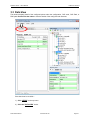
3.7.9 PMC Bit Point
The PMC bit status can be read or written by the server and displayed by the client. All addresses
available for the specific PMC type can be used (X,Y,G,F,A,C,D,E,K,M,N,T).
1) There are three ways to invoke the point configuration wizard…
On main menu – TOOLS WIZARDS POINT CONFIGURATION
Explorer View – RIGHT-CLICK on the machine or path and select ADD POINT
Explorer View – CLICK + toolbar button with the machine pre-selected
Since the machine was previously selected in the explorer view, the machine 16iMA-100
appears pre-selected in the MACHINE NAME list box.
2) Click the “NEXT” button. The path selection tab appears.
3) Select “PMC PATH” then click the “NEXT” button.
4) Select “PMC BIT” in the SELECT DATA TYPE list box.
D74C-0405-PB01/01
www.fanucfa.com
Page 60
FASOPC Server – User’s Manual
FANUC FA America
5) Select “PMC BIT” in the SELECT DATA TYPE list box.
6) Click the “NEXT” button. The point specifics tab appears.
The ACCESS field determines what operations the client may perform. R=read only, W=write
only, RW=read or write. Access RW is selected by default.
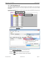
7) Select “F0 bit 7” then click the “NEXT” button. The Point Naming tab appears.
8) Enter “enter the point name”, for example: PMCBIT_F0_7.
This name will be used in the client point selection window.
NOTE
Decimal points may not be used when creating point names.
D74C-0405-PB01/01
www.fanucfa.com
Page 61
FASOPC Server – User’s Manual
FANUC FA America
9) Enter “CYCLE RUN STATUS” in the POINT DESCRIPTION field.
10) Click the “DONE” button, to complete the wizard.
The point should now appear in the OPC Explorer view.
D74C-0405-PB01/01
www.fanucfa.com
Page 62
FASOPC Server – User’s Manual
FANUC FA America
3.7.10 PMC Byte Point
The PMC byte status can be read or written by the server and displayed by the client. All
addresses available for the specific PMC type can be used (X,Y,G,F,A,C,D,E,K,M,N,T).
1) Right-click the “PMC PATH 1” branch.
2) Click “Add Point to PMC PATH 1” on the drop-down menu.
3) Click the “NEXT” button, the path selection tab will appear.
4) Click the “NEXT” button, the data type selection tab will appear.
5) Select “PMC BYTE” in the SELECT DATA TYPE list box.
D74C-0405-PB01/01
www.fanucfa.com
Page 63
FASOPC Server – User’s Manual
FANUC FA America
6) Click the “NEXT” button. The point specifics tab appears.
The ACCESS field determines what operations the client may perform. R=read only, W=write
only, RW=read or write. Access RW is selected by default.
The ARRAY SIZE setting allows you to view multiple addresses simultaneously while only
using one OPC server point. If ‘2’ is selected, byte data from D4 and D5 will be displayed.
7) Select “D4” and ARRAY Size “1” then click the “NEXT” button.
8) Enter “enter the point name”, for example: PMCBYTE_D4.
9) Enter “DATA 4” in the POINT DESCRIPTION field.
10) Click the “DONE” button, to complete the wizard.
D74C-0405-PB01/01
www.fanucfa.com
Page 64
FASOPC Server – User’s Manual
FANUC FA America
3.7.11 PMC 2Byte Point
The PMC 2byte status can be read or written by through the client. Naturally all D registers are 8
bits, but they may be concatenated to create data storage for larger numbers. PMC timers are
two bytes by default.
1) Right-click the “PMC PATH 1” branch.
2) Click “Add Point to PMC PATH 1” on the drop-down menu.
3) Click the “NEXT” button, the path selection tab will appear.
4) Click the “NEXT” button, the data type selection tab will appear.
5) Select “PMC 2BYTE” in the SELECT DATA TYPE list box.
D74C-0405-PB01/01
www.fanucfa.com
Page 65
FASOPC Server – User’s Manual
FANUC FA America
6) Click the “NEXT” button. The point specifics tab appears.
The ACCESS field determines what operations the client may perform. R=read only, W=write
only, RW=read or write. Access RW is selected by default.
The ARRAY SIZE setting allows you to view multiple addresses simultaneously while only
using one OPC server point. If ‘2’ is selected, byte data from D4 and D5 will be displayed.
7) Select “T2” and ARRAY Size “1” then click the “NEXT” button.
8) Enter “enter the point name”, for example: PMC2BYTE_T2.
9) Enter “TIMER 2” in the POINT DESCRIPTION field.
10) Click the “DONE” button, to complete the wizard.
D74C-0405-PB01/01
www.fanucfa.com
Page 66
FASOPC Server – User’s Manual
FANUC FA America
3.8 Load New Server Configuration
Any changes to the configuration file need to be saved and then exported to the server. The file is saved
in the C:\PROGRAMDATA\FANUCFAS\FASOPCUI folder as the working location, then it is exported to
the server in the directory C:\PROGRAMDATA\FANUCFAS\FASOPCServer on the serving PC.
3.8.1 Save Configuration File
Follow these steps to copy the configuration files to the server.
1) Click “FILE” on the top menu.
2) Click “Save Configuration” on the drop-down menu.
This will save myconfig2.FS2 file to the FASOPCUI directory folder of the local PC.
3) Click “FILE” on the top menu.
4) Select “EXPORT” on the drop-down menu.
5) Navigate to the “FASOPCServer” directory folder on the server PC.
The Default path is C:\PROGRAMDATA\FANUCFAS\FASOPCServer
6) Click the “OK” button.
The file ‘FASOPC.FS2’ will be created in the servers default folder.
This is required file name the OPC Server will load it’s configuration from.
3.8.2 Restart the Server
After the new FASOPC.FS2 file is exported to the FASOPCServer it must be restarted to initiate
the configuration changes. The server reads the new configuration file as it starts up.
1) Double-click the “OPC” icon in the system tray,
at the bottom near the clock.
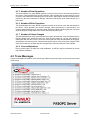
2) Click the “TRACE MESSAGES” tab, just below the drop-down menu.
3) Click “FILE” then “RESTART SERVER” on the drop-down menu.
Trace messages appear as the server restarts.
D74C-0405-PB01/01
www.fanucfa.com
Page 67
FASOPC Server – User’s Manual
FANUC FA America
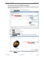
3.8.3 Connect to Server from FASOPC Configurator
The FASOPC configurator software is primarily used to create the server configuration file which
describes the machines and point data to collect. The configurator can connect to the server, to
show server status information also.
1) Click the “SERVER STATUS” tab next to the Data View tab.
2) Click “TOOLS” on the top menu.
3) Click “SERVER” on the drop-down menu.
4) Click “CONNECT TO SERVER” choice.
5) Click “LOCAL HOST” or enter the network path to your server, in the drop-down box.
6) Click the “CONNECT” button. The message CONNECTION SUCCESSFUL will appear.
D74C-0405-PB01/01
www.fanucfa.com
Page 68
FASOPC Server – User’s Manual
FANUC FA America
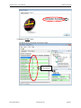
7) Click the “CLOSE” button.
The Server Status tab should now show live data.
Server Status
live data details.
D74C-0405-PB01/01
www.fanucfa.com
Page 69
FASOPC Server – User’s Manual
FANUC FA America
This page intentionally left blank.
D74C-0405-PB01/01
www.fanucfa.com
Page 70
FASOPC Server – User’s Manual
FANUC FA America
4 FASOPC Server
D74C-0405-PB01/01
www.fanucfa.com
Page 71
FASOPC Server – User’s Manual
FANUC FA America
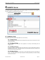
4 FASOPC Server
This chapter details the FASOPC Server user interface software. The server-side user interface is
provided to display current statistics and trace activity.
1) Double-Click the “FASOPC SERVER” icon in the Windows system tray.
The server user interface will open.
4.1 Statistics View
The statistics view shows real time data related to the server activity.
4.1.1 Sample Period
This is the number of milliseconds that must elapse before a point value is returned to the client
since the last update.
4.1.2 Number of Clients
This field indicates how many OPC client programs are currently communicating with this
FASOPC server.
4.1.3 Number of Groups
As points are added to subscription lists in the OPC server, they are placed within groups for
management by the server. This field indicates how many groups have been created on the
server by all currently connected clients.
4.1.4 Number of Items
The OPC server provides value to users when it returns data about points the client wishes to
receive. This field indicates how many total points are being requested by all clients currently
connected to the server.
D74C-0405-PB01/01
www.fanucfa.com
Page 72
FASOPC Server – User’s Manual
FANUC FA America
4.1.5 Number of Read Operations
This field indicates how many READ requests occurred on the server in the last data update to
the clients. Read operations are specific requests, either synchronous or asynchronous, but are
not part of the subscription data being sent by the server. Subscription data is information that is
reported by the server whenever it changes, rather than making the client continually ask for a
point value.
4.1.6 Number of Write Operations
This field indicates how many WRITE requests occurred on the server in the last data update to
the clients. Write operations are specific requests, either synchronous or asynchronous, and
must be called specifically by a connected client. Executing a write operation gives the connected
client the ability to change data on the device defined by the OPC point.
4.1.7 Number of Values Changed
This field indicates how many unsolicited data items were reported back to the connected client in
the last update cycle. Unsolicited items are items that are added to a group, and tagged for
subscription with the OPC server. The server, seeing that the client has subscribed to the group,
will publish a data set every time it determines that point values of the group have changed. Data
items sent consist only of those that have changed their value since they were last reported.
4.1.8 License Expirations
Demo license expires 30 days from initial installation. A USB key may be purchased to license
this software indefinitely.
4.2 Trace Messages
The trace messages tab shows a server activity log. Different log levels may be set to provide more detail
of the activity.
D74C-0405-PB01/01
www.fanucfa.com
Page 73
FASOPC Server – User’s Manual
FANUC FA America
4.2.1 Log File Settings
For everyday use a log level of 1 will provide enough detail to accurately indicate server activity.
During setup or troubleshooting a log level of 5 shows the greatest detail of server processing.
1) Click “TRACE” on the top menu.
2) Click “LOG FILE SETTINGS” on the drop-down menu.
The Log File Setting window will open…
3) Click “OK” to close the window.
4.2.2 Log File Open Time
This sets the maximum amount of time the current server log file will be used. At the end of this
period a new log file will be created and the old file will remain in the LOGS directory folder. This
value is set in units of minute, default is 90 minutes. Setting range is 0~2,147,483,647.
4.2.3 Log File Maximum Lifetime
This sets how long the log file will remain in the server LOGS directory folder. This value is set in
units of days, default is 14 days. Any log files that remain in the folder for more than 14 days will
be automatically deleted from the folder. Setting range is 0~32,767.
4.2.4 Log File Level
This setting determines how detailed the server log messages will be. Log level 1 is the least
amount of logging and is used for typical day to day operations. Log level 5 is the most detailed
logging level and is used when troubleshooting a connection or server problem.
4.3 File Menu
4.3.1 Request Clients to Disconnect
This selection sends a message to the connected OPC clients requesting they disconnect. This is
useful when a new configuration file (.FS2) is downloaded to the server.
4.3.2 Force Server Exit
Normally the server will not close while clients are connected. This function forces the server to
shut down even with clients connected.
4.3.3 Restart Server
This function restarts the server. The connected clients will notice a momentary delay in
information flow.
D74C-0405-PB01/01
www.fanucfa.com
Page 74
FASOPC Server – User’s Manual
FANUC FA America
4.4 Help Menu
The help menu currently has only one selection, which is ABOUT. The ABOUT box indicates the product
name, version, and licensing status.
1) Click “HELP” on the top menu.
2) Click “ABOUT” on the drop-down menu.
The ABOUT box will appear…
Version 1.0.0.0 is the first production release of this software.
D74C-0405-PB01/01
www.fanucfa.com
Page 75
FASOPC Server – User’s Manual
FANUC FA America
This page intentionally left blank.
D74C-0405-PB01/01
www.fanucfa.com
Page 76
FASOPC Server – User’s Manual
FANUC FA America
5 Troubleshooting
D74C-0405-PB01/01
www.fanucfa.com
Page 77
FASOPC Server – User’s Manual
FANUC FA America
5 Troubleshooting
This chapter provides details of the expected system startup sequence and troubleshooting when fault
messages occur.
5.1 Expected Start-up Sequence
5.1.1 Server Start-up
The server automatically starts running when FASOPC Configurator or any client attempts to
connect. Once the server is running, an OPC icon appears in the Windows system tray.
Depending on the Windows settings it may be necessary to mouse click in the system tray area
to see the OPC Server icon.
1) Double-Click the “FASOPC Configurator” icon on the desktop.
The user interface will open.
2) Click “FILE” on the top menu.
3) Click “Open Configuration” on the drop-down menu.
4) Select <your current configuration file>.
5) Click the “OPEN” button.
6) Click the “SERVER STATUS” tab next to the Data View tab.
D74C-0405-PB01/01
www.fanucfa.com
Page 78
FASOPC Server – User’s Manual
FANUC FA America
7) Click “TOOLS” on the top menu.
8) Click “SERVER” on the drop-down menu.
9) Click “CONNECT TO SERVER” choice.
10) Choose <your server> in the drop-down box.
11) Click the “CONNECT” button. The message CONNECTION SUCCESSFUL will appear.
The OPC icon should now appear in the Windows system tray.
12) Click the “CLOSE” button.
D74C-0405-PB01/01
www.fanucfa.com
Page 79
FASOPC Server – User’s Manual
FANUC FA America
The OPC icon should now appear in the Windows system tray.
13) Double-click the “OPC”’ icon in the system tray.
This is a sample
of the start-up
sequence when
the demo license
is applied.
Immediately after
this
sequence,
the server starts
loading
the
points/tags that
are configured in
the file.
A log file for the
client you are
using is probably
provided by the
client developer.
This file may also
have
relevant
status messages.
D74C-0405-PB01/01
www.fanucfa.com
Page 80
FASOPC Server – User’s Manual
FANUC FA America
5.2 Fault Messages
This section details the messages that may occur when operating the FASOPC software.
5.2.1 Connection Failed
When connecting to the server from the FASOPC Configurator user interface, the message
CONNECTION FAILED appears.
Open the server user interface and check the trace messages generated at this time.
D74C-0405-PB01/01
www.fanucfa.com
Page 81
FASOPC Server – User’s Manual
FANUC FA America
This page intentionally left blank.
D74C-0405-PB01/01
www.fanucfa.com
Page 82
FASOPC Server – User’s Manual
FANUC FA America
NOTES
D74C-0405-PB01/01
www.fanucfa.com
Page 83
FASOPC Server – User’s Manual
FANUC FA America
Appendix A – Revision History
Edition
01
Date
2013.01.22
D74C-0405-PB01/01
Comments
Original release
www.fanucfa.com
Section/
Related
Page
S/W
All
1.0.0.0
Page 84
FANUC FA America
Product Engineering Solutions
For questions on information in this manual: [email protected]
For CNC technical support: 888-FANUC-US (888-326-8287)
Find more FANUC CNC product information at www.fanucfa.com
Technical data is subject to change without prior notice. No part of this document may be reproduced in any form. All rights reserved.
© 2013 FANUC FA America Corporation
FANUC FA America
1800 Lakewood Boulevard
Hoffman Estates, IL 60192
Tel: 888-FANUC-US (888-326-8287)
Fax: 847-898-5001
[email protected]
Canada
6774-A Financial Dr.
Mississauga, ON LN5 7J6
Tel: 888-326-8287
Fax: 905-812-0053
Mexico
Av. Gustavo Baz # 2160 Edificio 4 PB
Col. Fracc. Ind. La Loma
Tlalnepantle, Mexico
Tel: 52 555-010-3400
Fax: 52 555-010-3410
Brazil
Av. Professor Celestino Bourroul 414
São Pailo, SP 02710-000, Brazil
Tel: 55 11-3952-8888
Fax: 55-11-3856-0848
Argentina
Av. Juan de Garay 2275/2283
C1256AAE Buenos Aires, Argentina
Tel: 54 11-4942-8504
Fax: 54 11-4942-1319
Atlanta, GA
Boston, MA
Charlotte, NC
Cincinnati, OH
Cleveland, OH
Dallas, TX
Denver, CO
Des Moines, IA
Detroit, MI
Ft. Wayne, IN
Hartford, CT
Houston, TX
Indianapolis, IN
Knoxville, TN
Long Island, NY
Los Angeles, CA
Milwaukee, WI
Minneapolis, MN
Nashville, TN
Philadelphia, PA
Phoenix, AZ
Pine Brook, NJ
Portland, OR
Rochester, NY
San Francisco, CA
Seattle, WA
St. Louis, MO
Tampa, FL
Tulsa, OK
Guelph
Montreal
Toronto
Monterrey
Querétaro
Belo Horizonte
Campinas
Caxias do Sul
Curitiba
Manaus
São Paulo
Buenos Aires
www.fanucfa.com
888-FANUC-US (888-326-8287)
All rights reserved.
© 2013 FANUC FA America Corporation