1
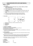
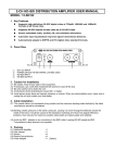
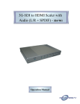
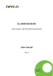
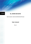
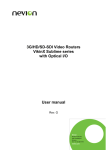
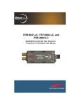
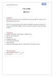
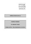
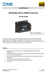
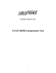
3G/HD/SD-SDI TO OPTICAL FIBER CONVERTER USER MANUAL MODEL: 15-SF101-10K / 15-SF101-30K 1. Key Features Built-in a SM fiber module that the HD-SDI could be transmitted between DVR side and camera over one fiber cable. Supports high-definition HD-SDI digital video at 720p60, 1080i60 and 1080p30 formats at all frame rates. Supports HD-SDI signals data rates up to 3G-SDI video. Passes embedded audio, ancillary ID, metadata information. Automatic input equalization improves signal transmission distances. Automatically adapts to SMPTE, ITU and DVB ASI digital video standard formats. 2. Panel View 1 ○ ①. ②. ③. ④. ⑤. 2 ○ 3 ○ 4 ○ 5 ○ 4 ○ 5 ○ 15-SF101T POWER IN, HD-SDI INPUT HD-SDI OUTNPUT (BUFFERED LOOP OUT) OPTICAL FIBER PLUG IN POWER ON, HD-SDI SIGNAL LOCKED LEDs 1 ○ 2 ○ 3 ○ 15-SF101R ①. ②. ③. ④. POWER IN, HD-SDI OUTPUT OPTICAL FIBER PLUG IN POWER ON, HD-SDI SIGNAL LOCKED LEDs 3. Caution for Installation 3.1 3.2 3.3 3.4 3.5 Be careful; never let any water in this equipment. If necessary, use a soft cloth moistened with alcohol to wipe off the dust. Be extra careful not to shake the unit. Avoid places where temperatures exceed 50°C or higher. Avoid places where there are frequent vibrations or shocks. When any abnormalities occur, make sure to unplug the unit and contact your local dealer. 4. Cable Installation 4.1 The coaxial cable is not squeezed at any position and the maximum bending radius defined by the cable manufacturer should be considered. 4.2 Bending creates pressure on the center conductor, causing it to move through the dielectric toward the inside of the bend. It would be caused to the impedance matching and return loss (signal reflection) problems, then reduces the maximum possible cable length and signal quality and reliability. 4.3 Avoid any BNC - adapter or any connectors in the BNC cable. Looping HD-SDI signals by BNC T-connectors to other devices is not possible. 5. Packing 5.1 3G-SDI to Fiber Transmitter 5.2 3G-SDI to Fiber Receiver 5.3 User Manual 5.4 Screws 5.5 Plastic-Conical-Anchor 5.6 Power Adaptor ×2 [Option] ×1 ×1 ×1 ×4 ×4 6. Specification 15-SF101-10K 15-SF101-30K MODEL 15-SF101T SDI Signal Formats Input Data Rata Min. Input Level Max. Input Level Output Level Distance Auto data rate detection Impedance Input Connector Output Connector Indicators Red LED Green LED Power Input Voltage Input Current Input Connector Optical Module COP Part Number Module Connector Type Fiber Connector Wavelength TX Power RX Sensitivity Mechanical & Environmental Weight Dimensions (W × L × H) Operation Temperature Storage Temperature 15-SF101R SD-SDI,HD-SDI, and 3G-SDI digital component video 270Mbps /1.485Gbps / 2.97Gbps 0.5Vp-p 1.2Vp-p 0.8Vp-p typical ■1.485Gbps: 170 m (550') using RG6 cable 120 m (400') using RG59 cable ■2.970Gbps: 100 m (330') using RG6 cable 70 m (230') using RG59 cable Yes 75Ω BNC × 1 N/A BNC × 1 Power On HD-SDI Locked 12 VDC <120 mA @ 12 VDC < 90 mA @ 12 VDC DC-JACK OD:2.0mm 34009110T1(15-SF101-10K) 3400961001 34009130T1(15-SF101-30K) SFP-type Single-mode(SM) LC 1310nm 1260 to 1620 nm 0 to -5 dBm N/A N/A 0 to -20 dBm < 175g (6.17 oz) < 170g (6.00 oz) 61 × 116 × 37 mm (2.40” × 4.57” × 1.45”) -10°C ~ 50°C -30°C ~ 85°C 7. Connection Diagram Q2012/12/20