1
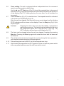
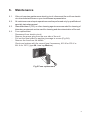
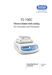
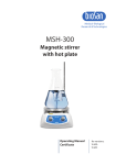
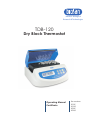
Medical–Biological
Research & Technologies
TDB-120
Dry Block Thermostat
Operating Manual
Certificate
for versions:
V.1AE
V.1AD
V.2AE
V.2AD
Contents
1.
Safety Precautions
2.
General Information
3.
Getting Started
4.
Operation
5.
Specifications
6.
Maintenance
7.
Warranty and Claims
8.
Declaration of Conformity
2
1.
Safety Precautions
The following symbols mean:
Caution!
Make sure you have fully read and understood the present
Manual before using the equipment. Please pay special
attention to sections marked by this symbol.
Caution!
Surfaces can become hot during use.
GENERAL SAFETY
·
Use only as specified in the Operating Manual provided.
·
The unit should be saved from shocks or falling.
·
After transportation or storage keep the unit under room temperature for 2-
3hrs before connecting to electric circuit.
·
Use only cleaning and decontamination methods recommended by the
manufacturer.
·
Do not make modifications to the design of the unit.
ELECTRICAL SAFETY
·
Connect only to electric circuit with voltage corresponding to that on the
serial number label.
·
Do not plug the unit into an ungrounded power socket, and do not use an
ungrounded extension lead.
·
Ensure that the switch and the plug are easily accessible during use.
·
If liquid penetrates into the unit, disconnect it from electric circuit and have it
checked by a repair and maintenance technician.
·
Disconnect the unit from electric circuit before moving.
·
Do not operate the unit in premises where condensation can form. Operating
conditions of the unit are defined in the Specifications section.
3
DURING OPERATION
Use only tubes of standard size.
·
·
Do not check the temperature by touch. Use a thermometer.
·
Do not leave the operating unit unattended.
·
Do not operate the unit in environments with aggressive or explosive
chemical mixtures. Please contact manufacturer for possible operation of the
unit in specific atmospheres.
Do not operate the unit if it is faulty or has been installed incorrectly.
·
Do not use outside laboratory rooms.
·
BIOLOGICAL SAFETY
·
It is the user's responsibility to carry out appropriate decontamination if
hazardous material is spilt on or penetrates into the equipment.
2. General Information
TDB-120 Dry-Block Thermostat has been designed for heating and
maintaining the set temperature in the aluminium block with special sockets for tubes.
TDB-120 Dry-Block Thermostat has obvious advantages when working with the
microquantities of the reagents used in the microtubes. The device possesses unprecedentedly high precision and uniformity of temperature distribution over the block.
Two models are available offering a choice of tube configurations to meet the
needs of many standard laboratory procedures:
·
Block A-53 21 x 0.5 ml + 32 x 1.5 ml microtubes
·
Block A-103 21 x 0.5 ml + 32 x 1.5 ml + 50 x 0.2 ml microtubes.
The TDB-120 device is applicable in:
for PCR analyses, for temperature
stabilisation in DNA/RNA restriction and
denaturation reaction;
·
BIOCHEMISTRY –
for the enzyme processes analyses;
·
MICROBIOLOGY –
for the anaerobic microorganism
cultivation,
·
CHEMISTRY –
for the preliminary heating of reagents in
chromatography (especially when
analysing chemical and biological
components of fatty acids, which
condense in cold microsyringes).
·
MOLECULAR AND GENE –
ENGINEERING, CELL BIOLOGY
4
3.
Getting started
3.1.
Unpacking.
Remove packing materials carefully and retain them for future shipment or
storage of the unit. Examine the unit carefully for any damage incurred during
transit. The warranty does not cover in-transit damage.
3.2.
Complete set. Package contents:
TDB-120 Thermostat with lid and aluminium block ..................................1 pce.
power cord ..............................................................................................1 pce.
spare fuse (inside fuse holder).................................................................1 pce.
Operating manual, Certificate.................................................................1 copy
3.3.
Set up:
place the unit upon even horizontal non-flammable surface at least 20 cm away
from any flammable materials;
remove protective film from the display;
plug the power cord into the socket on the rear side, and position the unit so that
there is easy access to the power switch and the plug.
5
4.
Operation
Recommendations during operation
Please check the tubes before using, be sure that tubes are thermoresistant.
Don't heat the tubes over the melting point of the material they are made of.
Remember that thin-walled tubes have a higher thermoconducting factor.
·
Tube caps can open under the action of high temperature (> 85°C) thus causing
sample volume shrinkage or potential health risk when working with infected
material. To prevent such cases it is recommended to use tubes with cap lock of
Safe-Lock® type.
·
Do not fill tubes more than 3-5 mm over the level they are immersed into the
heating block.
3
1
4
5
6
2
7
8
01:30
STOP
o
40.0 C
o
39.1 C
TDB-120
Fig.1 Control panel
4.1.
Connect the power cord to a grounded power socket and switch ON (position I)
the power switch located on the rear panel of the unit.
4.2.
The unit will turn on and the following readouts will be shown on the display:
previously set time and temperature in the upper line (Set);
timer indication STOP and current temperature in the lower line (Actual).
4.3.
Temperature setting. Use the p
and q
Temp. keys (Fig.1/6) to set the
required temperature, using as a guide the set temperature readouts shown in
the upper line of the display (Fig.1/3). Pressing the key for more than 2 s will
increase the increment.
4.4.
The unit will start heating. The actual temperature is shown in the lower line of
the display (Fig.1/4).
4.5.
When the required temperature is reached, open the heating block lid and place
tubes into the block sockets.
6
4.6.
Timer setting. The unit is equipped with an independent timer for convenient
control over the sample incubation time.
Use the p
and q
Time keys (Fig.1/5) to set the required time in hours and
minutes (hr:min), using as a guide the set time readouts shown in the upper line
of the display (Fig.1/1). Pressing the key for more than 2 s will increase the
increment.
4.7.
Press the Run key (Fig.1/7) to start the timer. The elapsed time will be indicated
in the lower line of the display (Fig.1/2).
After the set time elapses, the timer will give a sound signal and the blinking
STOP indication will be shown on the display. Press the Stop key (Fig.1/8) to
stop the signal.
Caution!
Stopping the timer does not stop the heating / temperature
maintenance process. The heating can be stopped by reducing
the temperature below 25°C using the q
T, C key (Fig. 1/6)
(OFF indication will be shown on the display, fig.1/3).
4.8.
The timer can be stopped before the set time elapses if required by pressing
Stop key. Pressing the Run key again will restart the timer with the same set
time interval.
4.9.
The set time interval can be changed at any time during the timer operation just stop the timer and make the changes required.
4.10. If the working time is set to 00:00, the unit will operate non-stop.
4.11. After finishing the operation turn OFF (position O) the unit with the power switch
at the rear panel and disconnect the unit from electric circuit.
7
5.
Specification
The unit is designed for operation in cold rooms, incubators and closed
laboratory rooms at ambient temperature from +4°C to +40°C in a non-condensing
atmosphere and maximum relative humidity 80% for temperatures up to 31°C
decreasing linearly to 50% relative humidity at 40°C.
5.1.
Temperature specifications
·
Setting range .......................................................................+25°C to +120°C
·
Control range .................................................5°C above ambient ... +120°C
·
Setting resolution ...................................................................................0.1°C
·
Stability at +37°C .................................................................................± 0.1°C
·
Uniformity at +37°C .............................................................................± 0.1°C
·
Over temperature protection .....................................internal thermal breaker
5.2.
General specifications
·
Digital time setting range ............................................................1 min–96 hrs
·
Display ..................................................................................LCD, 2õ16 signs
·
Dimensions .........................................................................230x210x110 mm
·
Working voltage .....................................120 V; 50/60 Hz or 230 V; 50/60 Hz
·
Consumed power (120 V/230 V) ....................200 W (1.7 A)/200 W (870 mA)
·
Weight* ..................................................................................................2.8 kg
*Accurate within ±10%.
TDB-120 with the built-in block
Catalogue number
A-53:
21 x 0.5 ml + 32 x 1.5 ml tubes
BS-010401-PAA
A-103:
21 × 0.5 ml + 32 × 1.5 ml + 50 × 0.2 ml tubes
BS-010401-QAA
Biosan is committed to a continuous programme of improvement and reserves
the right to alter design and specifications of the equipment without additional notice.
8
6.
Maintenance
6.1.
If the unit requires maintenance electric circuit, disconnect the unit from electric
circuit and contact Biosan or your local Biosan representative.
6.2.
All maintenance and repair operations must be performed only by qualified and
specially trained personnel.
6.3.
Standard ethanol (75%) or other cleaning agents recommended for cleaning of
laboratory equipment can be used for cleaning and decontamination of the unit.
6.4.
Fuse replacement
Disconnect from electric circuit.
Remove the power plug from the rear side of the unit.
Pull out the fuse holder by applying leverage in recess (Fig.2/A).
Remove the fuse from the holder.
Check and replace with the correct fuse if necessary, M 2 A for 230 V or
M 4 A for 120 V, (type M - time lag: Medium).
A
Fig.2 Fuse replacement
9
7.
Warranty and Claims
7.1.
The Manufacturer guarantees the compliance of unit with the requirements
of Specifications, provided the Customer follows the operation, storage and
transportation instructions.
7.2.
The warranted service life of unit from date of delivery to the Customer is 24
months. Contact your local distributor to check availability of extended
warranty.
7.3.
If any manufacturing defects are discovered by the Customer, an
unsatisfactory equipment report shall be compiled, certified and sent to the
local distributor address. Please visit www.biosan.lv, Technical support section
to obtain the claim form.
7.4.
The following information will be required in the event that warranty or postwarranty service comes necessary. Complete the table below and retain for
your records.
Model
Serial number
Date of sale
10
TDB-120 Dry Block Thermostat
8.
Declaration of Conformity
11
Biosan SIA
Ratsupites 7, build.2, Riga, LV-1067, Latvia
Phone: +371 67426137 Fax: +371 67428101
http://www.biosan.lv
Version 1-2.04 - January 2015