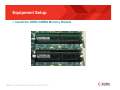
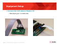
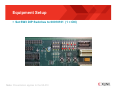
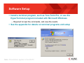
1
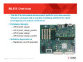
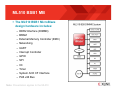
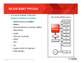
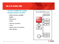
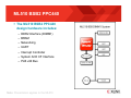
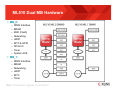
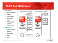
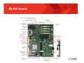
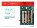
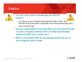
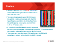
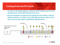
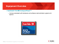
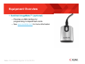
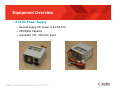
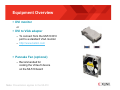
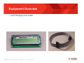
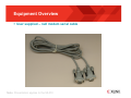
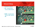
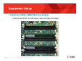
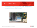
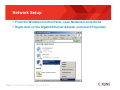
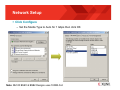
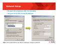
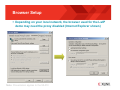
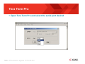
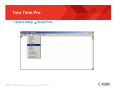
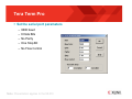
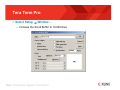
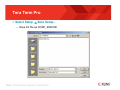
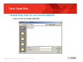
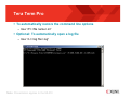
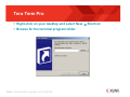
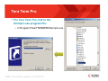
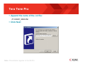
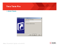
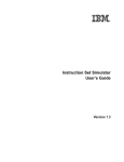
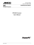
ML510 Overview and Setup Overview of the Hardware Designs and Software Applications How to set up the equipment, software, CompactFlash, network, and terminal programs May 2009 ML510 Overview ML510 Overview Equipment Overview Equipment Setup Software Setup CompactFlash Setup Network Setup Appendix ML510 Overview The ML510 embedded development platform provides several reference designs and a versatile hardware platform for rapid prototyping and system verification Hardware Designs – ml510_bsb1_design – ml510_bsb1_design_ppc440 – ml510_bsb2_design – ml510_bsb2_design_ppc440 Software Applications – Standalone non-OS applications Note: Presentation applies to the ML510 ML510 BSB1 MB The ML510 BSB1 MicroBlaze design hardware includes: – DDR2 Interface (DIMM0) – BRAM – External Memory Controller (EMC) – Networking – UART – Interrupt Controller – GPIO – SPI – IIC – Timer – System ACE CF Interface – PLB v46 Bus Note: Presentation applies to the ML510 ML510 BSB1 PPC440 The ML510 BSB1 PPC440 design hardware includes: – DDR2 Interface (DIMM0) – BRAM – External Memory Controller (EMC) – Networking – UART – Interrupt Controller – GPIO – SPI – IIC – System ACE CF Interface – PLB v46 Bus Note: Presentation applies to the ML510 ML510 BSB2 MB The ML510 BSB2 MicroBlaze design hardware includes: – DDR2 Interface (DIMM1) – BRAM – Networking – UART – Interrupt Controller – Timer – System ACE CF Interface – PLB v46 Bus Note: Presentation applies to the ML510 ML510 BSB2 PPC440 The ML510 BSB2 PPC440 design hardware includes: – DDR2 Interface (DIMM1) – BRAM – Networking – UART – Interrupt Controller – System ACE CF Interface – PLB v46 Bus Note: Presentation applies to the ML510 ML510 Dual MB Hardware MB_0: – – – – – – – – – DDR2 Interface BRAM EMC (Flash) Networking UART INTC & GPIO SPI & IIC Timer System ACE MB_1: – – – – – – DDR2 Interface BRAM Networking UART INTC Timer Note: Presentation applies to the ML510 ML510 Dual MB Hardware PPC440_0: – – – – – – – – DDR2 Interface BRAM EMC (Flash) Networking UART INTC & GPIO SPI & IIC System ACE PPC440_1: – – – – – DDR2 Interface BRAM Networking UART INTC Note: Presentation applies to the ML510 Also Available From Xilinx These items are not included with the ML510, but are available for purchase from Xilinx: – Xilinx IDS (ISE Design Suite) • Includes ISE and XPS – Platform Cable USB These items are required to run the ML510 presentations Note: Presentation applies to the ML510 IDS Software Requirements Xilinx ISE 11.1 software Xilinx EDK 11.1 software Note: Presentation applies to the ML510 ChipScope Software Requirements Xilinx ChipScope Pro 11.1 software Note: Presentation applies to the ML510 Optional Software Wind River Workbench 2.5 ML510 Board Features the Xilinx Virtex™-5 XC5VFX130T FPGA Note: Presentation applies to the ML510 ML510 Board 3.3V and 5V PCI Slots The ML510 has both 3.3V and 5V PCI Slots A 3.3V Slot can be identified by the board silkscreen (1) or by the 3.3V Key (2) 2 A 5V Slot can be identified by the board silkscreen (3) or by the 5V Key (4) 4 Note: Presentation applies to the ML510 1 3 Caution You will short-circuit and damage your ML510 board if – You plug in a non-compliant Universal PCI add-in card - one that has its 5V power pins connected to the VI/O special power pins into a 3.3V PCI slot You are responsible for ensuring that your Universal PCI addin card is compliant with the PCI Local Bus Specification version 2.3 (PCI v2.3), section 4.4.1. Xilinx is not responsible for any damage due to the use of non-compliant add-in cards. Note: Presentation applies to the ML510 Caution The ML510 board has both 3.3V and 5V PCI slots and can accept a Universal PCI add-in card into any slot To prevent damage to your ML510 board, the add-in card must comply with the PCI Specification and drive its I/O buffers from the VI/O special power pins and not from 3.3V or 5V power pins If your Universal PCI add-in card is powered by non-compliant power connections instead of VI/O connections, do not plug it into a PCI slot on the ML510 board You must test your Universal PCI add-in card for PCI v2.3 compliance before using it with the ML510 board Note: Presentation applies to the ML510 Testing Universal PCI Cards As seen in the drawing below, red pins are 5V; yellow pins are 3.3V; and blue pins are the VI/O special power pins. Use an ohmmeter to measure the impedance from VI/O to a 5V pin, and from VI/O to a 3.3V pin. If you find VI/O shorted to either 3.3V or 5V, do not use this add-in card with the ML510 board. Note: Presentation applies to the ML510 Equipment Overview SanDisk® 512 MB CompactFlash™ – Comes preloaded with hardware and software demonstration systems for ML510 Note: Presentation applies to the ML510 Equipment Overview SanDisk ImageMate™ (optional) – Provides a USB interface for programming CompactFlash cards – See www.sandisk.com for more information Note: Presentation applies to the ML510 Equipment Overview ATX PC Power Supply – Used to supply DC power to the ML510 – 250 Watts Capacity – Automatic 100 - 240 VAC Input Note: Presentation applies to the ML510 Equipment Overview DVI monitor or DVI to VGA adapter – To connect from the ML510 DVI port to a standard VGA monitor – http://www.belkin.com Pancake Fan (optional) – Recommended for cooling the Virtex-5 device on the ML510 board Note: Presentation applies to the ML510 Equipment Overview LCD Display and cable Note: Presentation applies to the ML510 Equipment Overview User supplied – null modem serial cable Note: Presentation applies to the ML510 Equipment Overview Ethernet cables Note: Presentation applies to the ML510 Equipment Overview User supplied – SATA “Crossover” Cable – Available at www.cable-connection.com • Part number C0003935 Note: Used in the IBERT Design Network Setup Connect the ML510 Ethernet port to a Gigabit Ethernet Adapter Top port is for PHY0 – MII and RGMII – BSB1 and Dual Designs Bottom port is for PHY1 – SGMII only – BSB2 and Dual Designs Note: Presentation applies to the ML510 Network Setup Set PHY0 Jumpers MII – Connect pins 1 & 2 on J50 and J28 RGMII – Connect pins 1 & 2 on J50; connect J49 Note: Refer to the ML510 User Guide – UG356 for details Equipment Setup Install the DDR2 DIMM1 Memory Module – Press down firmly on both ends; clips will snap into place Note: Presentation applies to the ML510 Equipment Setup Install the DDR2 DIMM0 Memory Module Note: Presentation applies to the ML510 Equipment Setup Connect the LCD cable to Header J13 – Red strip by pin 1 on both ends Note: Presentation applies to the ML510 Equipment Setup Set SW3 DIP Switches to 00010101 (1 = ON) Note: Presentation applies to the ML510 Software Setup Install a terminal program, such as Tera Term Pro, or use the HyperTerminal program included with Microsoft Windows – Required to input the commands, and view the results See the appendix for details on terminal programs and setup Note: Presentation applies to the ML510 CompactFlash Setup Insert the CompactFlash provided with the ML510 fully into the CompactFlash slot on the ML510 board Note: Presentation applies to the ML510 Network Setup From the Windows Control Panel, open Network Connections Right-click on the Gigabit Ethernet Adapter and select Properties Note: Presentation applies to the ML510 Network Setup Click Configure – Set the Media Type to Auto for 1 Gbps then click OK Note: ML510 BSB1 & BSB2 Designs uses 100Mb Full Network Setup Reopen the properties after the last step Set your host (PC) to this IP Address: Note: Some presentations use other IP addresses; change as directed Browser Setup Depending on your local network, the browser used for the LwIP demo may need the proxy disabled (Internet Explorer shown) Note: Presentation applies to the ML510 Appendix Terminal Programs – Tera Term Creating Desktop Shortcuts Terminal Programs Terminal programs are used to communicate with the processor Terminal programs in this setup use a serial interface Free programs are available – Tera Term Pro (recommended) • http://hp.vector.co.jp/authors/VA002416/teraterm.html Note: Presentation applies to the ML510 Tera Term Pro Open Tera Term Pro and select the serial port desired Note: Presentation applies to the ML510 Tera Term Pro Select Setup → Serial Port… Note: Presentation applies to the ML510 Tera Term Pro Set the serial port parameters – 9600 baud – 8 Data Bits – No Parity – One Stop Bit – No Flow Control Note: Presentation applies to the ML510 Tera Term Pro Select Setup → Window… – Increase the Scroll Buffer to 10,000 lines Note: Presentation applies to the ML510 Tera Term Pro Select Setup → Save Setup… – Save init file as COM1_9600.INI Note: Presentation applies to the ML510 Tera Term Pro Repeat these steps for your second COM port – Save init file as COM2_9600.INI Note: Presentation applies to the ML510 Tera Term Pro To automatically restore the command line options – Use “/F=<file name>.ini” Optional: To automatically open a log file – Use “/L=<log file>.log” Note: Presentation applies to the ML510 Tera Term Pro You can add shortcuts to your desktop for Tera Term Pro This works especially well for Tera Term Pro since the command line options can be added here – You can create different shortcuts to run the desired speed as seen below Note: Presentation applies to the ML510 Tera Term Pro Right-click on your desktop and select New → Shortcut Browse for the terminal program folder Note: Presentation applies to the ML510 Tera Term Pro For Tera Term Pro, link to the ttermpro.exe program file: – C:\Program Files\TTERMPRO\ttermpro.exe Note: Presentation applies to the ML510 Tera Term Pro Append the name of the .ini file: /F=COM1_9600.INI Click Next Note: Presentation applies to the ML510 Tera Term Pro Click Finish Note: Presentation applies to the ML510 Documentation Virtex-5 – Silicon Devices http://www.xilinx.com/products/devices.htm – Virtex-5 Multi-Platform FPGA http://www.xilinx.com/products/virtex5/index.htm – Virtex-5 Family Overview: LX, LXT, SXT, and FXT Platforms http://www.xilinx.com/support/documentation/data_sheets/ds100.pdf – Virtex-5 FPGA DC and Switching Characteristics Data Sheet http://www.xilinx.com/support/documentation/data_sheets/ds202.pdf Documentation Virtex-5 – Virtex-5 FPGA User Guide http://www.xilinx.com/support/documentation/user_guides/ug190.pdf – Virtex-5 FPGA Configuration User Guide http://www.xilinx.com/support/documentation/user_guides/ug191.pdf – Virtex-5 System Monitor User Guide http://www.xilinx.com/support/documentation/user_guides/ug192.pdf – Virtex-5 Packaging and Pinout Specification http://www.xilinx.com/support/documentation/user_guides/ug195.pdf Documentation Virtex-5 RocketIO – RocketIO GTP Transceivers http://www.xilinx.com/products/virtex5/lxt.htm – RocketIO GTP Transceiver User Guide – UG196 http://www.xilinx.com/support/documentation/user_guides/ug196.pdf – RocketIO GTX Transceivers http://www.xilinx.com/products/virtex5/fxt.htm – RocketIO GTX Transceiver User Guide – UG198 http://www.xilinx.com/support/documentation/user_guides/ug198.pdf Documentation Design Resources – IDS - ISE Design Suite http://www.xilinx.com/tools/designtools.htm – ISE Manuals http://www.xilinx.com/support/documentation/dt_ise11-1.htm – ISE Command Line Tools User Guide http://www.xilinx.com/support/documentation/sw_manuals/xilinx11/devref.pdf – ISE Development System Libraries Guide http://www.xilinx.com/support/documentation/ sw_manuals/xilinx11/virtex5_hdl.pdf Documentation Additional Design Resources – Customer Support http://www.xilinx.com/support – Xilinx Design Services: http://www.xilinx.com/xds – Titanium Dedicated Engineering: http://www.xilinx.com/titanium – Education Services: http://www.xilinx.com/education – Xilinx On Board (Board and kit locator): http://www.xilinx.com/products/devkits/boardsearch.htm Documentation Platform Studio – Embedded Development Kit (EDK) Resources http://www.xilinx.com/tools/platform.htm – Embedded System Tools Reference Manual http://www.xilinx.com/support/documentation/sw_manuals/xilinx11/est_rm.pdf – EDK Concepts, Tools, and Techniques http://www.xilinx.com/support/documentation/ sw_manuals/xilinx11/edk_ctt.pdf Documentation PowerPC 440 – Embedded Processor Block in Virtex-5 FPGAs Reference Guide – UG200 http://www.xilinx.com/support/documentation/user_guides/ug200.pdf – PPC440 Virtex-5 Wrapper – DS621 http://www.xilinx.com/support/documentation/ip_documentation/ ppc440_virtex5.pdf – DDR2 Memory Controller for PowerPC 440 Processors – DS567 http://www.xilinx.com/support/documentation/ip_documentation/ ppc440mc_ddr2.pdf Documentation MicroBlaze – MicroBlaze Processor http://www.xilinx.com/tools/microblaze.htm – MicroBlaze Processor Reference Guide – UG081 http://www.xilinx.com/support/documentation/sw_manuals/mb_ref_guide.pdf Documentation ChipScope Pro – ChipScope Pro 10.1i Serial IO Toolkit User Manual http://www.xilinx.com/ise/verification/chipscope_pro_siotk_10_1_ug213.pdf – ChipScope Pro 11.1i ChipScope Pro Software and Cores User Guide http://www.xilinx.com/support/documentation/ sw_manuals/xilinx11/chipscope_pro_sw_cores_11_1_ug029.pdf Documentation Memory Solutions – Demos on Demand – Memory Interface Solutions with Xilinx FPGAs http://www.demosondemand.com/clients/xilinx/001/page_new2/index.asp#35 – Xilinx Memory Corner http://www.xilinx.com/products/design_resources/mem_corner – Additional Memory Resources http://www.xilinx.com/support/software/memory/protected/index.htm – Xilinx Memory Interface Generator (MIG) 3.0 User Guide http://www.xilinx.com/support/documentation/ip_documentation/ug086.pdf – Memory Interfaces Made Easy with Xilinx FPGAs and the Memory Interface Generator http://www.xilinx.com/support/documentation/white_papers/wp260.pdf Documentation Ethernet – Virtex-5 Embedded Tri-Mode Ethernet MAC Wrapper Data Sheet http://www.xilinx.com/support/documentation/ip_documentation/ v5_emac_ds550.pdf – Virtex-5 Embedded Tri-Mode Ethernet MAC Wrapper Getting Started Guide http://www.xilinx.com/support/documentation/ip_documentation/ v5_emac_gsg340.pdf – Virtex-5 Tri-Mode Ethernet Media Access Controller User Guide http://www.xilinx.com/support/documentation/user_guides/ug194.pdf – LightWeight IP (lwIP) Application Examples – XAPP1026 http://www.xilinx.com/support/documentation/application_notes/xapp1026.pdf Documentation PCIe – LogiCORE Endpoint Block Plus for PCI Express Data Sheet http://www.xilinx.com/support/documentation/ip_documentation/ pcie_blk_plus_ds551.pdf – LogiCORE Endpoint Block Plus for PCI Express Designs http://www.xilinx.com/support/documentation/ip_documentation/ pcie_blk_plus_ug341.pdf – LogiCORE Endpoint Block Plus Getting Started Guide for PCI Express Designs http://www.xilinx.com/support/documentation/ip_documentation/ pcie_blk_plus_gsg343.pdf – Virtex-5 Integrated Endpoint Block User Guide for PCI Express Designs http://www.xilinx.com/support/documentation/user_guides/ug197.pdf Documentation System Generator – System Generator for DSP http://www.xilinx.com/tools/sysgen.htm – Xilinx System Generator for DSP Getting Started Guide – UG639 http://www.xilinx.com/support/documentation/ sw_manuals/xilinx11/sysgen_ref.pdf – Xilinx System Generator for DSP Getting Started Guide – UG639 http://www.xilinx.com/support/documentation/ sw_manuals/xilinx11/sysgen_gs.pdf – Virtex-5 XtremeDSP Design Considerations User Guide – UG193 http://www.xilinx.com/support/documentation/user_guides/ug193.pdf Documentation PLB v4.6 IP – Processor Local Bus (PLB) v4.6 – DS531 http://www.xilinx.com/support/documentation/ip_documentation/plb_v46.pdf – Multi-Port Memory Controller (MPMC) – DS643 http://www.xilinx.com/support/documentation/ip_documentation/mpmc.pdf – XPS Multi-CHannel External Memory Controller (XPS MCH EMC) – DS575 http://www.xilinx.com/support/documentation/ip_documentation/ xps_mch_emc.pdf – XPS LocalLink TEMAC – DS537 http://www.xilinx.com/support/documentation/ip_documentation/ xps_ll_temac.pdf Documentation PLB v4.6 IP – XPS LocalLink FIFO – DS568 http://www.xilinx.com/support/documentation/ip_documentation/ xps_ll_fifo.pdf – XPS IIC Bus Interface – DS606 http://www.xilinx.com/support/documentation/ip_documentation/xps_iic.pdf – XPS SYSACE (System ACE) Interface Controller – DS583 http://www.xilinx.com/support/documentation/ip_documentation/ xps_sysace.pdf – XPS Timer/Counter – DS573 http://www.xilinx.com/support/documentation/ip_documentation/xps_timer.pdf Documentation PLB v4.6 IP – XPS Interrupt Controller – DS572 http://www.xilinx.com/support/documentation/ip_documentation/xps_intc.pdf – Using and Creating Interrupt-Based Systems Application Note http://www.xilinx.com/support/documentation/application_notes/xapp778.pdf – XPS General Purpose Input/Output (GPIO) – DS569 http://www.xilinx.com/support/documentation/ip_documentation/xps_gpio.pdf – XPS External Peripheral Controller (EPC) – DS581 http://www.xilinx.com/support/documentation/ip_documentation/xps_epc.pdf Documentation PLB v4.6 IP – XPS 16550 UART – DS577 http://www.xilinx.com/support/documentation/ip_documentation/ xps_uart16550.pdf – XPS Thin Film Transistor (TFT) Controller – DS695 www.xilinx.com/support/documentation/ip_documentation/xps_tft.pdf – XPS PS2 Controller – DS707 www.xilinx.com/support/documentation/ip_documentation/xps_ps2.pdf – XPS Block RAM (BRAM) Interface Controller – DS596 www.xilinx.com/support/documentation/ip_documentation/ xps_bram_if_cntlr.pdf Documentation OPB Bridge IP – PLBV46 to OPB Bridge – DS403 http://www.xilinx.com/support/documentation/ip_documentation/ plbv46_opb_bridge.pdf – On-Chip Peripheral Bus V2.0 with OPB Arbiter – DS401 http://www.xilinx.com/support/documentation/ip_documentation/opb_v20.pdf Documentation IP – Local Memory Bus – DS445 http://www.xilinx.com/support/documentation/ip_documentation/lmb_v10.pdf – Block RAM Block – DS444 http://www.xilinx.com/support/documentation/ip_documentation/ bram_block.pdf – Microprocessor Debug Module – DS641 http://www.xilinx.com/support/documentation/ip_documentation/mdm.pdf – LMB Block RAM Interface Controller – DS452 http://www.xilinx.com/support/documentation/ip_documentation/ lmb_bram_if_cntlr.pdf Documentation IP – JTAGPPC Controller – DS298 http://www.xilinx.com/support/documentation/ip_documentation/ jtagppc_cntlr.pdf – Processor System Reset Module – DS402 http://www.xilinx.com/support/documentation/ip_documentation/ proc_sys_reset.pdf – Clock Generator v2.0 – DS614 http://www.xilinx.com/support/documentation/ip_documentation/ clock_generator.pdf Documentation IP – Utility Vector Logic – DS481 http://www.xilinx.com/support/documentation/ip_documentation/ util_vector_logic.pdf – Utility IO Multiplexer – DS694 http://www.xilinx.com/support/documentation/ip_documentation/ util_io_mux.pdf Documentation ML510 – ML510 Overview http://www.xilinx.com/ml510 – ML510 Evaluation Platform User Guide – UG356 http://www.xilinx.com/support/documentation/boards_and_kits/ug356.pdf – ML510 Reference Design User Guide – UG355 http://www.xilinx.com/support/documentation/boards_and_kits/ug355.pdf – ML510 QuickStart Tutorial http://www.xilinx.com/products/boards/ml510/docs/ml510_quickstart.pdf Documentation ML510 – ML510 Schematics http://www.xilinx.com/support/documentation/boards_and_kits/ ml510_schematics.pdf – ML510 Bill of Material http://www.xilinx.com/support/documentation/boards_and_kits/ ml510_bom.xls