1
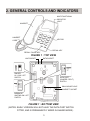
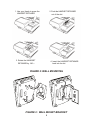
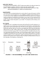
GEMINI SERIES
TELEPHONE
MODEL IQ330
OPERATING INSTRUCTIONS
16
CONTENTS
1. FEATURES ....................................................................... 2
2. GENERAL CONTROLS AND INDICATORS .................... 3
MULTIFUNCTIONAL INDICATOR LIGHT ............................................................................. 4
RINGER VOLUME SWITCH ................................................................................................. 4
ALPHA-NUMERIC KEYPAD ................................................................................................. 4
CRADLE SWITCH ................................................................................................................ 4
RECALL KEY ........................................................................................................................ 4
BASIC OPERATION .............................................................................................................. 5
REDIAL / PAUSE KEY .......................................................................................................... 5
HEARING-AID COMPATIBILITY ........................................................................................... 5
3. ADVANCED NETWORK OPERATION ............................. 6
PAUSE FUNCTION WHEN DIALING .................................................................................... 6
HOLDING AND TRANSFERRING CALLS ............................................................................ 6
4. INSTALLATION ................................................................. 7
UNPACKING ......................................................................................................................... 7
GENERAL SETTING-UP ....................................................................................................... 7
LOCATION ............................................................................................................................ 7
WALL MOUNTING ................................................................................................................ 7
LINE CONNECTION ........................................................................................................... 10
TECHNICAL ADJUSTMENTS - FOR CORRECT OPERATION ......................................... 10
MESSAGE WAITING LIGHT COMPATIBILITY ................................................................... 10
DATA PORT SWITCH ......................................................................................................... 11
SHARED MODE .................................................................................................................. 11
SPLIT MODE ....................................................................................................................... 11
5. GENERAL CARE AND MAINTENANCE ........................ 12
CLEANING .......................................................................................................................... 12
FAILURE TO OPERATE AND SERVICE DIFFICULTIES .................................................... 12
6. THUNDERSTORMS ....................................................... 13
7. WARRANTY - 3 YEARS ................................................. 13
8. SERVICE CENTRES ...................................................... 14
1
1. FEATURES
•
Tone dialing
•
Super bright LED ringer lamp allows visual ringing indication
•
Built-in switchable Message Waiting option to suit any neon (80 VDC) type message
waiting system AND Ericsson BP250 Message Waiting (other system types optional)
•
User selectable ringer volume
•
Redial and Pause functions
•
Recall facility with flash timing 100 mS
•
Switchable data port allows connection to a second line to enable simultaneous
voice and data
•
Compatible with direct lines, intelligent networks, PABXs and any analog line
•
Call Waiting compatible
•
Telstra Customnet compatible
•
Line powered, unaffected by mains power interruption
•
REN (Ringer Equivalence Number) = 0.68 allows multiple parallel devices on the
same line without loading incoming ring
•
Alpha-numeric keypad allows full access to services that require the entering of
numerals and letters
•
Fully modular connection provides maximum ease of installation on desk or wall
•
3 years warranty
•
Hearing Aid compatibility
2
2. GENERAL CONTROLS AND INDICATORS
MULTIFUNCTIONAL
INDICATOR
LIGHT
HANDSET
HANDSET
CORD
KEYPAD
RECALL KEY
REDIAL / PAUSE KEY
FIGURE 1 : TOP VIEW
LINE SOCKET
DATA SOCKET
RINGER
HI / LOW / OFF
SWITCH
DATA PORT
(SHARED / SPLIT)
SWITCH
WALL MOUNT HOLE
HANDSET SOCKET
MESSAGE
WAITING ON / OFF
SWITCH
FIGURE 1 : BOTTOM VIEW
(NOTES: EARLY VERSION WILL NOT HAVE THE DATA PORT SWITCH
FITTED, AND IS PERMANENTLY WIRED IN SHARED MODE.)
3
MULTIFUNCTIONAL INDICATOR LIGHT
There are two different functions:
Ring Indicator:
Flashes when the telephone rings with an incoming call
Message-Waiting Indicator: Illuminates when a message is waiting in your voicemail
system (depends on system compatibility). The built-in
Message Waiting option suits any neon (80 VDC) type
message waiting system and also the telephone has
Ericsson BP250 Message Waiting built-in (other system
types are optional extras).
RINGER VOLUME SWITCH
The three available positions allow selection of OFF (no sound), LOW volume, and
HIGH volume of the telephone's ringing sound during an incoming call.
ALPHA-NUMERIC KEYPAD
The standard numeric digits are available for normal dialing. The alphabetic characters
are provided to allow full access to services that require the entering of numerals and
letters.
CRADLE SWITCH
Located in the handset cradle, this plastic lever is depressed by the handset (when
placed in the cradle) to cut off the line. Note: Depressing this cradle lever too briefly
when intending to terminate a call may result in an accidental "hookflash" that will
inadvertently place the call on hold. This is known as "phantom calls" because the held
call will probably ring again at your extension within a few minutes (the other party will
have hung up, so it will seem as if you were called by a phantom, hence the name
"phantom calls"). If you experience this problem, when terminating your call please
depress the cradle lever a little longer before making/receiving your next call (i.e. it is
not a system or telephone fault).
RECALL KEY
For use with host telephone systems to invoke special network facilities such as callhold or call-transfer available in your system.
4
BASIC OPERATION
The telephone can be used as a normal telephone; lift the HANDSET to answer an
incoming call, or lift the HANDSET and dial on the KEYPAD to commence an outgoing
call. Please refer to the appropriate sections to learn more about advanced operating
instructions.
REDIAL / PAUSE KEY
Redial Function
Press to redial the last number previously dialed, which may be up to 32 digits long.
Dialing more than 32 digits during one call will cause erasure of the entire number from
the redial memory.
EXAMPLE : TO REDIAL LAST NUMBER
1. Lift HANDSET,
2. Press REDIAL .
Pause Function
The Pause command may be needed if your phone is connected to any network where
a pause is required (e.g. between internal and external dial tones).
For manual dialing:
1. Lift HANDSET.
2. Dial any digits required before the pause
3. Press PAUSE
4. Dial the remaining digits.
DATA PORT AND SWITCH
The data port provides access to the telephone line for computers (with a modem),
answering machines and cordless phones. The Data Port switch (see figure 4 & 5)
determines whether the Data Port shares the line with the telephone (position shared)
or has its own line (position split).
(Note: EARLY VERSION WILL NOT HAVE THE DATA PORT SWITCH FITTED, AND
PERMANENTLY WIRED IN SHARED MODE.)
HEARING-AID COMPATIBILITY
Provided as a standard feature for users with a “T switch” type hearing-aid.
5
3. ADVANCED NETWORK OPERATION
Where this telephone is used on an intelligent network such as Easycall, Customnet,
Centel, a PABX or other network the following information may be useful.
PAUSE FUNCTION WHEN DIALING
Depending on your telephone system, this may or may not be required. If in doubt,
check with your system supplier or Interquartz dealer, as failure to observe your system's
requirements may lead to difficulty in making outgoing external calls. If you have
determined that a pause is required by your host system, please refer to the PAUSE
Function section to ensure correct usage of the PAUSE button.
HOLDING AND TRANSFERRING CALLS
The method used for these functions is dependent on your system type, so you will
need to check your system's Extension User Guide. The RECALL KEY is typically used
to transfer calls.
6
4. INSTALLATION
UNPACKING
The carton contains the following :
• Telephone body and handset
• Coiled cord and line cord
• This User Manual.
GENERAL SETTING-UP
1. Fit the COILED CORD to the appropriate sockets in the HANDSET and the telephone
base
2. Fit the LINE CORD to the rear socket and to your telephone network outlet
3. Set the Ringer Volume
4. See following sections to complete the installation.
LOCATION
The telephone should be placed on a desk, table or shelf where it is not likely to be
pushed off. If the unit is to be wall mounted, it should be seated securely on the WALL
MOUNTING BRACKET. Avoid excessive heat, damp, dust, direct sunlight, vibration,
and other appliances or devices that may transmit or emit electrical or electromagnetic
radio frequency noise or signals (e.g. computers, welders, pagers).
WALL MOUNTING
1. Fit the WALL MOUNT BRACKET (optional, not supplied) to the wall and attach the
WALL MOUNT BRACKET to the underside of telephone (see Figure 2)
2. To enable the HANDSET to be supported in the cradle, follow the procedure shown
in (Figure 2) to reverse the HANDSET RETAINER.
3. NOTE: The WALL MOUNT BRACKET and MODULAR WALL JACK illustrated in
(Figure 2) are available from your authorised Interquartz dealer and can be ordered
as "Wall Mount Kit No.3".
7
1. Use your thumb to press the
2. Push the HANDSET RETAINER
HANDSET RETAINER
out of the slot.
3. Rotate the HANDSET
4. Insert the HANDSET RETAINER
RETAINER by 180
back into its slot.
FIGURE 2: WALL MOUNTING
FIGURE 2 : WALL MOUNT BRACKET
8
WALL-MOUNT BRACKET (OPTIONAL NOT INCLUDED WITH PHONE)
LUG "B"
LUG "A"
MOUNTING
HOLE "E"
PIVOT FOR SWING-OUT
PLATE USED FOR
MODEL IQTEL 25
LUG "C"
LUG "D"
MOUNTING HOLE "F"
Please note:
1. This wall bracket may be secured onto the wall by using mounting holes "E" and "F"
2. Lugs to break off before wall mounting the phone.
TELEPHONE MODELS
IQ 90
IQ 150
IQ 250
IQ 260
IQ 360
IQ 350
IQ 450
IQ 550
IQ E2
IQ E3
BREAK OFF LUGS
IQTEL 80
IQTEL 300
IQTEL 500
IQTEL E1
IQTEL E2
IQTEL E3
IQTEL ET
STUDIO 20
GEMINI IQ33X SERIES
"B" and "D"
IQTEL 25
"A" and "C"
IQ 300
9853 XT
9835 MKII
9836
9837
"A" ONLY
FIGURE 3
9
LINE CONNECTION
This telephone is supplied with a RJ45 Plug as the wall plug, with the centre pair being
reserved for speech and signaling. Other types of plugs and cords are available on
request.
TECHNICAL ADJUSTMENTS - FOR CORRECT OPERATION
MESSAGE WAITING LIGHT COMPATIBILITY
Located in the Multifunctional Indicator Light, the Message Waiting Light can be optionally
configured at time of order to be compatible with most host telephone systems on the
Australian market. The standard factory fitted message waiting light is a neon style
circuit suitable for minimum 80V DC signaling and is compatible with NEC, FUJITSU,
ALCATEL, later HYBREX and NORTEL PABX systems. The Message Waiting Light
switch is located on the telephone's underside which enables or disables the light, and
is factory set in the ON position.
If this telephone is configured to “message waiting” mode please note that it is only for
PABX systems (contact your vendor for clarification). If so, it may not be connected to
any other telephone system or network without the authority of the Australian
Telecommunications Authority. For direct line use, please disable the message waiting
feature using the switch on the telephone’s underside.
LINE SOCKET
DATA SOCKET
RINGER
HI / LOW / OFF
SWITCH
DATA PORT
(SHARED / SPLIT) SWITCH
WALL MOUNT HOLE
HANDSET SOCKET
MESSAGE
WAITING ON / OFF
SWITCH
FIGURE 4
(Note: EARLY VERSION WILL NOT HAVE THE DATA PORT SWITCH FITTED,
AND PERMANENTLY WIRED IN SHARED MODE.)
10
DATA PORT SWITCH
The data port switch (SHARED or SPLIT) determines whether the data port shares the
line with telephone (position “shared”) or has its own line (position “split”)
(NOTE: EARLY VERSION WILL NOT HAVE THE DATA PORT SWITCH FITTED,
AND ARE PERMANENTLY WIRED IN SHARED MODE.)
SHARED MODE
This mode uses one analog telephone line and provides the user with access to a Data
Port, but in this mode the telephone’s voice capability is disabled while the Data Port is
in use.The line cord as supplied is terminated with RJ45 at the wall end. For Shared
mode the telephone line should be terminated on pins 4 and 5 of the matching RJ45
compatible wall socket. Different plug or cord types can be provided to suit your wall
socket - please contact Interquartz or your dealer. The telephone will be factory set in
Shared mode.
SPLIT MODE
To enable the user to simultaneously access both the Data Port and the telephone (i.e.
“Split” mode) a second analog line must be allocated to the Data Port, and the Data Port
Mode Switch must be set to Split mode. The line cord as supplied is terminated with
RJ45 at the wall end, with the voice pair in the middle (pins 4 and 5) and the dedicated
data line pair (for “Split” mode) on pins 3 and 6. For Split mode the telephone line pair
should be terminated on pins 4 and 5 of the matching RJ45 compatible wall socket. The
new dedicated analog DATA line pair must be terminated on pins 3 and 6 of the RJ45
compatible wall socket where the voice pair is also located. Different plug or cord types
can be provided to suit your wall socket - please contact Interquartz or your dealer. The
telephone will be factory set in Shared mode. The Data Port Mode Switch is found on
the underside of the telephone. (See figure 5)
FIGURE 5 PIN ASSIGNMENT OF RJ45 LINE CORD PLUG
11
5. GENERAL CARE AND MAINTENANCE
This telephone is a precision electronic instrument. While in use and storage, care should
be taken to avoid rough handling, extreme temperature, and damp or dirty environments.
CLEANING
NEVER use aerosol sprays or other chemical agents or substances that leaves a residue
(furniture polish for example).
Use a mild detergent and a damp, clean cloth when cleaning. Do not allow moisture to
enter the telephone's interior - damage may result!
FAILURE TO OPERATE AND SERVICE DIFFICULTIES
If telephone service problems occur at any time, it is recommended that the installation
procedure described in this manual be re-checked.
If a fault occurs, try to determine if the fault is with the telephone, or with the network or
system to which the telephone is connected:
Disconnect the "suspect" telephone, and test the line with a substitute telephone. If the
telephone service then operates satisfactorily, the fault is in the "suspect" telephone.
Test the "suspect" telephone on a known good line. If the fault still occurs, the fault is in
the "suspect" telephone.
Consult your Interquartz dealer for further advice if necessary.
12
6. THUNDERSTORMS
The telephone, in common with household electrical appliances, can be a source of
electric and acoustic shock during thunderstorms. The possibility of a telephone user
experiencing a shock is minimal. Nevertheless, customers should be aware of some
simple precautions to follow during thunderstorms:
Use your telephone only for calls of the utmost urgency. Keep these calls brief.
Whilst using your telephone keep clear of electrical appliances and metal fixtures such
as: stoves, air conditioners, refrigerators, window frames and sinks.
7. WARRANTY - 3 YEARS
Interquartz (A'Asia) Pty Ltd warrants the original purchaser against failure, under normal
usage and in the environment and network for which it was designed, resulting from
defective material and workmanship at time of manufacture for a period of THREE
YEARS from the date of purchase. Proof of purchase and date of purchase are required
for determining validity of this warranty. This warranty does not cover defects or damage
due to normal wear and tear, negligence, accidents, exposure to radiation, misuse,
obsolescence, incompatibility, improper maintenance, lightning strikes or unauthorised
repairs or modifications and excludes freight or postage costs to/from your local
authorised service centre unless otherwise arranged. Consequential loss not included.
Notification of any defect must be made within the warranty period before a warranty
repair can be effected. This guarantee is in addition to all other Warranties or Guarantees
expressed or implied by the Trade Practices Act or other Commonwealth or State laws
and all other obligations and liabilities on the part of Interquartz (A'Asia) Pty. Ltd.
13
8. SERVICE CENTRES
Please call Modern Communication Systems 5522 2222
to arrange service or repair of your telephone.
14
Manufactured by
International Quartz Limited
A Subsidiary of Chiaphua Industries Ltd.
3C933001-03B
©Copyright INTERNATIONAL QUARTZ LTD. 2002
15