1
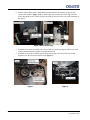
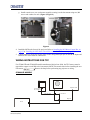
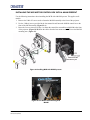
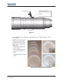
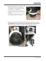
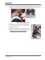
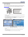
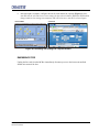
M25 Motorized Lens Mount
Instruction Sheet
INTRODUCTION
Use the following instructions to replace or upgrade existing non-motorized lens mounts on CP2000XB/SB and CP2000-ZX models with the M25 Motorized Lens Mount, which incorporates stepper
motors for horizontal/vertical offsets, zoom and focus.
The entire procedure requires removal of the lamp (in CP2000-XB) some re-wiring between the Touch
Panel Controller (TPC) and projector (in CP2000-XB/SB), adding a new lens boot (in CP2000-ZX),
adding a zoom gear and stepper motor to the projection lens, installing the M25 Motor Control Box
(MCB), and performing boresight alignment.
This procedure should be completed by a qualified service technician. Depending on your projector
model, it can take up to 2 hours to complete a full lens mount replacement and setup.
IMPORTANT: Make sure your projector has been upgraded with the latest software to ensure the
motorized lens mount will function properly. Main software v2.9 is required for CP2000-XB/SB, and
v2.2 is required for CP2000-ZX projectors. Visit www.christiedigital.com for the latest software
downloads.
KITS REQUIRED
To install a M25 Motorized Lens Mount:
• 108-127101-01 M25 Motorized Lens Mount Kit for CP2000-ZX
• 108-340108-01 M25 Motorized Lens Mount Kit for CP2000-SB
• 108-341109-01 M25 Motorized Lens Mount Kit for CP2000-XB
To upgrade a non-motorized Lens Mount: (applies to CP2000-ZX (116-001113-xx), CP2000-SB(106-004116-xx),
CP2000-XB(101-001113-xx)
• 108-128102-01 M25 Motor Upgrade Kit (includes 3 stepper motors and wiring to upgrade an existing nonmotorized lens mount, choke assembly)
M25 Motorized Lens Mount Instruction Sheet
020-100309-03 (12-2009)
1 of 21
TOOLS REQUIRED
•
•
•
•
•
•
#1, #2 Phillips screwdrivers, and small flathead screwdrivers
3 & 5 mm hex keys
13mm ratchet
wire cutters
Christie Protective Clothing Safety Kit P/N 598900-095 (required when accessing and removing the lamp)
Ruler (to measure distance between lens mount and projector front bezel)
SAFETY WARNINGS AND GUIDELINES
Always power down and disconnect all power sources to the projector before
servicing or cleaning.
For CP2000-XB/SB: Wear authorized protective clothing whenever the lamp
door is open. Never attempt to remove the lamp directly after use. The lamp is under increased
pressure when hot and may explode, causing personal injury and/or property damage.
Refer to the product user manual for complete lamp safety and removal
instructions.
NOTICE: When adjusting the M25 Motorized Lens Mount on a projector that has a Motorized
Auxiliary Lens Mount (MALM), swing the MALM completely out of the way to ensure it does not
collide with the lens as it is being adjusted.
NOTICE: Always perform a Lens Reset (in software) after adjusting the Horizontal and Vertical offset
knobs to bring the lens mount back to a zero position before proceeding with other adjustments.
Failure to do so may limit the range of motion of the lens mount.
INSTALLATION INSTRUCTIONS
INSTALLING THE M25 MOTORIZED LENS MOUNT
1. Remove the projection lens from the projector and set aside in an area where it cannot be damage.
Refer to the User Manual for instructions.
2. Remove the existing lens mount.
a. If applicable, swing the MALM completely out of the way so it will not interfere with the
installation of the new lens mount.
b. Center the lens mount vertically and horizontally.
c. Remove the 3 screws securing the lens mount to the front of the projector.
d. For CP2000-XB/SB models, unwrap the aluminum tape securing the rubber boot to the lens
mount. Note: Keep the tape for reuse with the new lens mount. Remove the lens mount.
2 of 21
M25 Motorized Lens Mount Instruction Sheet
020-100309-03 (12-2009)
3. For CP2000-ZX models,
e. Remove the six, M4 screws securing the rubber boot to
the front plate. Retain for the installation of the new lens
boot.
f. Remove the six copper fingers, then remove the rubber
boot.
g. Install the new rubber boot provided in the kit using the
clamp ring and the six, M4 screws from Step 3.e. Do not
remove the loops of tape from the lens boot as they are
required when installing the new lens mount. (Figure
1)
Figure 1 CP2000-ZX - New
Lens Boot Installed
h. Thread the extra length of tape provided in the kit
through the loops of tape as shown in (Figure 2).
This tape will seal off the overlap between the lens
boot and lens mount (see Step 6.).
Figure 2 CP2000-ZX - Add extra
tape through loops
4. For CP2000-XB/SB projectors manufactured before June 2009, upgrade wiring to the TPC. Refer
to Wiring Instructions for TPC, on page 7.
5. For all projector models, install the MCB to the front of the projector. Refer to Installing the M25
Motor Control Box, on page 12. If you have a MALM installed, refer to Installing the M25 Motor
Control Box with a MALM Present, on page 15
6. Install the new lens mount.
a. Use the neck strap provided with your projector to hold the new lens mount while you slide the
lens boot cover over the lens mount.
b. For CP2000-ZX, push the lens barrel as far forward on the lens boot as possible making sure
the lens boot does not get wedged in between the lens barrel and the front plate. Reach your
hand inside the lens mount to adjust. (Figure 3)
M25 Motorized Lens Mount Instruction Sheet
020-100309-03 (12-2009)
3 of 21
c. Seal off the overlap between the lens boot and lens mount
using the tape on the lens boot for ZX and reusing the
aluminum tape from the old lens boot for CP2000-XB/SB
models.
Figure 3
d. Secure the lens mount to the projector reusing the
hardware from the old lens mount. IMPORTANT: The
distance between the lens mount and projector front
plate must measure 20 mm for CP2000-ZX and 19 mm
for CP2000-XB/SB. The figure on the right has been
provided in the event a ruler is not available during
installation. Cut out the portion applicable to your
model and do a quick measurement to ensure the
correct distance is achieved.
e. Install the Zoom motor assembly to the lens. Refer to
described later in this document.
7. Install the projection lens.
8. Calibrate the lens and perform boresight alignment.
4 of 21
Note: This document may not print to scale on some
printers. Use caution when using the ruler provided. If in
doubt, try and locate an actual ruler.
M25 Motorized Lens Mount Instruction Sheet
020-100309-03 (12-2009)
UPGRADING A NON-MOTORIZED LENS MOUNT
The following figure identifies all the parts and hardware required for upgrading a non-motorized lens
mount. Note: Part numbers are subject to change.
Figure 4 Motorized Lens Mount Exploded
1. Remove the projection lens from the projector and set aside in an area where it cannot be damage.
Refer to the User Manual for instructions.
2. For CP2000-XB/SB projectors manufactured before June 2009, upgrade wiring to the TPC. Refer
to Wiring Instructions for TPC, on page 7.
3. Install Focus and Offset motor assemblies:
a. Remove the focus and offset adjustment knobs from the lens mount. Keep focus knob
mounting hardware for later use.
b. Insert an adapter shaft (Figure 5) into each of the vacant mounting
holes from which the vertical and horizontal adjustment knobs were
removed in the previous step. This adapter resizes the opening to allow
for the installation of the offset motor assembly.
c. Install the vertical and horizontal offset motor assemblies by threading
the rod into the lens mount and then securing the bracket with 2, M6
screws and washers.
Figure 5
M25 Motorized Lens Mount Instruction Sheet
020-100309-03 (12-2009)
5 of 21
d. Install a sensor flag to each vertical and horizontal offset motor assembly using two, M3
screws with washers. (Figure 6) Do a visual inspection to ensure the sensor flag will move
freely through the sensor. Failure for the sensor flag to clear the sensor can result in damage to
the sensor.
Figure 6 Offset Sensor Flag
e. Install the focus motor assembly to the front of the lens mount reusing two, M4 screws with
washers that mounted the manual focus adjustment knob.
f. Install the focus sensor assembly and the focus sensor flag to the front of the lens mount.
Requires two, M3 screws and washer each. (Figure 7)
Figure 7
6 of 21
Figure 8
M25 Motorized Lens Mount Instruction Sheet
020-100309-03 (12-2009)
g. Install a metal cover over each motor assembly securing it to the lens mount using two, M4
screws and washers for each. (Figure 8, Figure 9)
Figure 9
4. Install the MCB to the front of the projector. Refer to Installing the M25 Motor Control Box, on
page 12 or Installing the M25 Motor Control Box with a MALM Present, on page 15.
5. Connect harnesses from each stepper motor to their designated input port on the MCB. Inputs and
harnesses are color coded for convenience.
WIRING INSTRUCTIONS FOR TPC
For CP2000-XB and CP2000-SB models manufactured before June 2009, the TPC harness must be
upgraded to support a serial link to the lens mount’s MCB. This must be done before installing the new
lens mount.
Remove the lamp before performing any projector re-wiring.
CP2000-XB MODELS
TPC
Projection Head
001-100411-xx
001-111028-xx
001-100132-xx
001-100155-xx
Belly Pan
MCB
001-111029-xx
M25 Motorized Lens Mount Instruction Sheet
020-100309-03 (12-2009)
7 of 21
1. Disconnect the TPC harness from the projector’s rear connector panel.
2. Remove the two screws securing the TPC connector.
Disconnect TPC harness and
remove TPC connector
3. Remove the projector belly pan.
a. Remove the eight screws from both the left
and right sides of the belly pan (Figure 10),
as well as the six screws along the back of
the belly pan.
4. Remove the lamp. Refer to the projector’s User
Manual for safety and installation instructions.
5. This step requires two people. One person
must carefully tilt the projector from the front
projection head in order for the other person to
have the required clearance to remove the belly
pan out from underneath the projector. Once the
belly pan is removed the wiring running
underneath the projector can be accessed.
Figure 10 Remove Projector’s Belly Pan
6. Remove the TPC harness from the projector: Unlock all
the P-clips used to secure the wire bundles under the
projector (Figure 11).
b. Using wire cutters, remove all tie-wraps from the
wire bundles.
c. Disconnect the TPC harness running underneath the
projector.
d. Carefully, pull the TPC harness out through the TPC
connector opening on the rear connector panel.
7. Disconnect the black Ethernet cable from the internal
ethernet hub. Carefully, pull the Ethernet cable through
the TPC connector opening on the rear connection panel.
8 of 21
Figure 11 Unlock P-Clips
M25 Motorized Lens Mount Instruction Sheet
020-100309-03 (12-2009)
8. Remove the nut securing the ground wire to the back
of the rear connector panel. (Figure 12)
9. Insert the TPC harness assembly (001-100155-xx)
through the TPC connector opening on the rear
connector panel. Note: This is a breakout cable that
includes the TPC power cable, the Ethernet cable,
ground wire and an RS232 cable.
a. Connect the TPC power cable to the connector
under the projector.
b. Plug the Ethernet connector into the internal
ethernet hub.
c. Secure the ground wire to the back of the rear
Figure 12 Remove Ground Wire
connector panel.
d. Secure the TPC connector to the rear connector panel.
10. Secure each of the P-clips loosened in Step 6. Tie-wrap each of the wire bundles.
11. Feed the TPC Cross RS232 harness (001-111029-xx) through the front of the projector, and over
top of the belly pan by the fold mirror access plate. Connect it to the loose RS232 connector on the
TPC harness assembly installed in Step 9. above. The other RS232 end connects to the Motor
Control Box (MCB).
12. Remove and re-wire the TPC (Figure 13):
a. Slide the TPC back cover off by
snapping it out of the two tabs at the
back.
b. Disconnect the LAN connector.
c. Using a small flathead screwdriver,
remove the two screws securing the
terminal block.
Figure 13 Upgrade TPC Wiring
M25 Motorized Lens Mount Instruction Sheet
020-100309-03 (12-2009)
9 of 21
d. Remove the three screws securing the green, black and red
wires in the terminal block. (Figure 14)
e. Unsnap the ferrite from the wire bundle.
Figure 14 Remove
Terminal Block Wires
f. Remove the TPC harness connector from the TPC.
Figure 15 Remove TPC
Connector
g. Feed the TPC Case harness assembly (001-100411-xx) through
the opening in the TPC, then connect the RS232 end to the
RS232 end of the TPC RS232 cable (001-111028-xx).
h. Secure the TPC connector end to the TPC.
i. Snap the ferrite around the new wire assembly.
j. Connect the RS232 connector to COMM1.
k. Connect the LAN.
l. Insert the red, black and green wires into the terminal block and
tighten the three screws.
Figure 16 TPC Case and
m. Tighten the two screws on the terminal block.
RS232 Harnesses
13. Replace the TPC back cover. Re-mount the TPC to the projector.
DO NOT reuse the existing power cable.
14. Connect the TPC Rear Panel Harness Assembly (001-100132-xx) to the TPC and the projector’s
rear connector panel TPC port.
10 of 21
M25 Motorized Lens Mount Instruction Sheet
020-100309-03 (12-2009)
FOR CP2000-SB MODELS
1. Open pedestal door to access the Communications and Source Connection panel located on the
underside of the projection head, near the front.
2. Disconnect the TPC harness from the internal Ethernet hub and 24V power supply.
3. Feed the TPC harness through the hole in the rear of the pedestal. Remove the TPC.
4. Re-wire the TPC (Same as Step 12. in CP2000-XB):
a. Slide the TPC back cover off by snapping it out of the two tabs at the back.
b. Disconnect the LAN connector.
c. Using a small flathead screwdriver, remove the two screws securing the terminal block.
d. Remove the three screws securing the green, black and red wires in the terminal block.
e. Unsnap the ferrite from the wire bundle.
f. Remove the TPC harness connector from the TPC.
g. Feed the TPC Case harness assembly (001-100411-xx) through the opening in the TPC, then
connect the RS232 end to the RS232 end of the TPC RS232 cable (001-111028-xx).
h. Secure the TPC connector end to the TPC.
i. Snap the ferrite around the new wire assembly.
j. Connect the RS232 connector to COMM1.
k. Connect the LAN.
l. Insert the red, black and green wires into the terminal block and tighten the three screws.
m. Tighten the two screws on the terminal block.
5. Connect the TPC-to-Ethernet harness assembly (001-100371-xx) to the internal Ethernet hub, and
the TPC power supply in the pedestal. Connect ground. Route the TPC connector end through the
hole in the rear of the pedestal.
6. Replace the TPC back cover. Re-mount the TPC to the projector.
7. Connect the TPC connector from the TPC-to-Ethernet harness assembly (Step 5) to the TPC.
M25 Motorized Lens Mount Instruction Sheet
020-100309-03 (12-2009)
11 of 21
INSTALLING THE M25 MOTOR CONTROL BOX
The Motor Control Box (MCB) is installed at the front of the projector using the same mounting holes
traditionally reserved for the MALM. However, the MCB and MALM can simultaneously be
mounted, if required. Refer to Installing the M25 Motor Control Box with a MALM Present, on page
15.
The MCB is wired to the projector with an RS-232 harness.
CP2000-XB/SB MODELS
1. Mount the MCB assembly.
a. Using the hardware provided,
mount the MCB assembly to
the two far left mounting
holes on the front panel. These
mounting holes are also used
for mounting the optional
Motorized Auxiliary Lens
Mount. (Figure 17)
2. Connect the harness from the
projector to the MCB COMM
port.
Figure 17 MCB Assembly Installed (CP2000-XB shown)
3. For CP2000-SB models only, connect the choke
assembly harness to the MCB power supply output
connector. (Figure 18)
4. Connect the power supply to MCB POWER 24
VDC port.
5. Connect the four lens mount motor harnesses to the
MCB faceplate. For example, connect the harness
from the X-axis motor (labeled red) to the X (also
labeled in red) on the MCB etc. Harnesses and
motors are color coded for easier installation. Note:
No connection is made to the optional AUX port. It
is for future use.
6. Connect a power cable from the MCB to a nearby
wall outlet.
Figure 18 Add DC Common Mode
Choke Assembly (CP2000-SB)
12 of 21
M25 Motorized Lens Mount Instruction Sheet
020-100309-03 (12-2009)
7. For CP2000-SB models only, open the pedestal door and verify that a snap on ferrite clamp is
secured around the ballast output leads. If the clamp is missing, install the one that has been
provided in the kit. Install as shown in Figure 19.
Figure 19 Snap on Ferrite Clamp Installed (CP2000-SB)
8. Secure a cable tie above and below the clamp. (Figure 19)
CP2000-ZX MODELS
1. Mount the MCB. (Figure 20)
a. Using the hardware provided,
mount the MCB assembly to
the two far left mounting
holes on the front panel.
These mounting holes are also
used for mounting the
optional Motorized Auxiliary
Lens Mount.
Figure 20 MCB Assembly Installed (CP2000-ZX shown)
M25 Motorized Lens Mount Instruction Sheet
020-100309-03 (12-2009)
13 of 21
2. Connect one end of the RS232 harness (016-101699-xx) to the MCB COMM port and the other
end to the RS232 B port located on the Projector Control Module (PCM). Proper routing of this
harness is under the projector along the track in the base plate and then up through the opening
near the PCM.
3. Connect the power supply to MCB POWER 24 VDC port.
4. Connect the all lens mount motor harnesses to the MCB faceplate. For example, connect the
harness from the X-axis motor (labeled red) to the X (also labeled in red) on the MCB etc.
Harnesses and motors are color coded for easier installation. Note: The optional AUX port is for
future use.
5. Connect the line cord from the MCB to a nearby wall outlet.
CONNECTION TO A PC (FOR ALL MODELS):
If you require a connection to a PC, use a female-to-female DB9 null modem cable from your PC or
laptop to the MCB COMM port.
NOTE: Depending on the computer being used, you may
need to manually wire transmit, receive and ground only. In
this case, connect pin 5 on both DB9’s together, connect pin
2 on the first end to pin 3 on the other, pin 3 on the first end
to pin 2 on the other.
6
7
8
9
1
5
2
4
3
3
4
2
5
1
9
8
7
6
Figure 21 Null Modem Cable
14 of 21
M25 Motorized Lens Mount Instruction Sheet
020-100309-03 (12-2009)
INSTALLING THE M25 MOTOR CONTROL BOX WITH A MALM PRESENT
Use the following instructions when installing the MCB with a MALM present. This applies to all
models.
1. Remove the 2 M6 x25 screws used to fasten the MALM assembly to the front of the projector.
2. Use the 2 M6x10 screws provided in the lens mount kit and fasten the MALM control box to the
front of the MCB assembly. (Figure 22-A)
3. Reuse the 2 screws removed in Step 1 to fasten the control box assemblies and MALM to the front
of the projector. (Figure 22-B) Route the cables from the lens mount to the MCB over the MALM
mounting arm. (Figure 23).
Figure 22 Installing MCB with MALM present
Figure 23 Lens Mount Cable Routing with
MALM
M25 Motorized Lens Mount Instruction Sheet
020-100309-03 (12-2009)
15 of 21
MOUNT ZOOM MOTOR ASSEMBLY TO LENS
Use the following procedure to install the Zoom Motor Assembly (Figure 24) to the lens you will be
using with the projector. This procedure applies to any of the available lenses for your projector model.
1. Attach the zoom motor assembly to the lens. Ensure the
center of the motor is aligned with the top of the lens
(use UP label as reference) and that the adjustment
screw on the clamp is positioned on the left side of the
UP label (see Figure 24).
2. Adjust the position of lens:
• Position the following lenses against the front of the
motor mount (see Figure 25):
> 1.6-2.4
> 1.8-3.0
> 2.15-3.6
• Position the following lens against the back of the motor
mount (see Figure 26):
> 1.45-2.5
Figure 24 Zoom Motor
and Clamp
For all other lenses, adjust the position of the lens so that a small gap is left between the lens zoom
ring and the motor mount to prevent rubbing and deterioration of the two components.
Figure 25
16 of 21
M25 Motorized Lens Mount Instruction Sheet
020-100309-03 (12-2009)
Figure 26
3. Use a 3 mm hex driver to tighten the clamp around the lens - Torque setting of 1 in-lb.
recommended.
4. Install the zoom gear ring and
zoom gear spacer suited for
your lens type. Spacers snap
into the grooves on the ring.
(Figure 27)
• Use the small adapter with
the 1.8-3.0 lens.
• Use the larger adapter with
the 1.45-2.05, and 2.15-3.6
lenses.
• No adapter required for other
lenses.
Figure 27 Zoom Ring and Zoom Gear Spacer
M25 Motorized Lens Mount Instruction Sheet
020-100309-03 (12-2009)
17 of 21
5. Slide the zoom gear ring over the zoom ring on the
lens. Tighten the screw on the zoom gear ring Torque setting of 3 in-lb. recommended. DO NOT
over-tighten this screw. (Figure 28)
6. Looking down at the lens rotate the zoom ring
clockwise until it stops (reaches the end of its range
of motion).
7. Line up the motor’s gear with the last few teeth on
the corresponding end of the lens ring gear.
Figure 28 Tighten Zoom Gear Ring
8. Rotate the zoom gear ring back and forth to ensure it runs smoothly and that the gear always
remains engaged with the zoom gear ring. The sensor flag should always remain in line with the
ring (Figure 29). Do a visual inspection to ensure the sensor flag will move freely through the
sensor. Failure for the sensor flag to clear the sensor can result in damage to the sensor.
Figure 29 Engage Gear
18 of 21
M25 Motorized Lens Mount Instruction Sheet
020-100309-03 (12-2009)
9. To prevent premature wear of the gear motor and zoom gear ring, check if there is a small gap
between the teeth of these parts. If fine tuning is required, loosen the screw on the gear motor in
small increments until a small gap between the teeth is evident. (Figure 30)
Figure 30 Fine Tuning Gear Position
10. Install the safety cover over the motor assembly (Figure 31).
Note: The harness on the sensor may need to be carefully bent
back a little to install the cover.
11. Install the projection lens.
12. Connect the harness from the lens into the M25 Motor Control
Box. This procedure varies for different projector models. Refer
to Installing the M25 Motor Control Box, on page 12.
Figure 31 Safety Cover
M25 Motorized Lens Mount Instruction Sheet
020-100309-03 (12-2009)
19 of 21
BASIC OPERATION
Before you begin operating the projector with the new lens mount, it is important that you perform
some basic optical alignment procedures to achieve optimized images on the screen. Refer to the User
Manual for more information on lens control options. Updated User Manuals can be found at
www.christiedigital.com.
Horizontal
Boresight
Bolt
Motorized
Vertical
Offset
Anchor
Bolt
Lock/
Unlock
Lens
Motorized
Horizontal
Offset
Focus
IMPORTANT!
Horizontal and Vertical Offset knobs are for
emergency use only. If the lens mount is
adjusted using these knobs, perform a Lens
Reset (in software) first to bring the lens
mount back to a zero position before
proceeding with other lens mount
adjustments. Failure to do this may limit the
range of motion of the lens mount.
Vertical
Boresight
Bolt
1. If applicable, swing the MALM out of the way to ensure it does not collide with the projection lens
as it is being adjusted.
2. From the Advanced>Lens menu, select the lens type installed. This step is extremely important to
allow the full range of motion for that lens. (Figure 32)
3. From the Advanced>Lens menu, select ILS Installed (default). Select Calibrate, to electronically calibrate the lens. (Figure 32)
CP2000-XB/SB
CP2000-ZX
Figure 32 Advanced Lens Menu
4. Once lens calibration is complete, display a “framing” test pattern or something equivalent with
crosshairs.
5. Adjust boresight to ensure the lens and lens mount are precisely adjusted in relation to the
projector’s internal optics:
a. Refer to the boresight instructions provided in the product User Manual.
20 of 21
M25 Motorized Lens Mount Instruction Sheet
020-100309-03 (12-2009)
6. After boresight is complete, configure the lens for each channel as required. (Figure 33) Note:
Auto ILS must be selected to over-write settings for the selected channel. With Auto ILS disabled,
changes made to lens settings are temporary and will be lost once Auto ILS is selected again.
CP2000-XB/SB
CP2000-ZX
Figure 33 Customizing Lens Settings for a Specific Channel
EMERGENCY STOP
Unplug the line cord from the MCB to immediately disconnect power to the lens mount and halt
further movement of the lens.
M25 Motorized Lens Mount Instruction Sheet
020-100309-03 (12-2009)
21 of 21