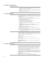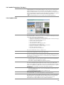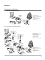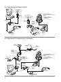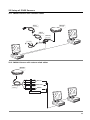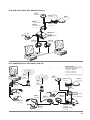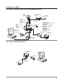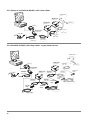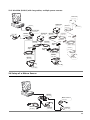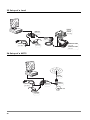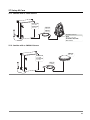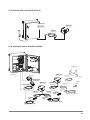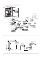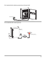
1
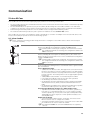
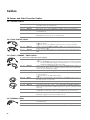
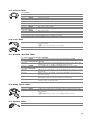
Structural Monitoring Equipment List Table of Contents Overview 1 5 Monitoring Systems 5 1.1 1.2 1.3 5 5 6 Main Components Setups Stable Reference Points Software 2 GeoMoS 2.1 2.2 2.3 2.4 2.5 2.6 2.7 2.8 2.9 2.10 3 7 GeoMoS Modules GeoMoS Monitor GeoMoS Monitor Options Sensor License GeoMoS Analyzer GeoMoS Analyzer Options GeoMoS Adjustment GeoMoS Demo (1 year) GeoMoS Evaluation (30 days) GeoMoS Web 7 7 8 8 9 9 10 10 10 11 11 Leica GNSS Spider 12 3.1 3.2 12 12 Required Options for Real Time Monitoring (RT Positioning Products) Required Options for Post Processed Monitoring (PP Positioning Products) 4 Leica GeoMoS HiSpeed 12 5 Leica SpiderQC 13 6 Leica CrossCheck 13 Sensors 7 8 14 Geodetic Sensors 14 7.1 7.2 7.3 7.4 7.5 7.6 7.7 7.8 7.9 7.10 7.11 7.12 7.13 7.14 7.15 7.16 7.17 14 14 14 14 14 14 14 15 15 15 16 16 16 17 17 17 17 TM30/TS30 Standard Reflectors Monitoring Reflectors 360° Reflectors Precision Reflectors Mini Reflectors Tribrachs Carriers Handles GNSS Sensors Holder and Mounting Kits for GR10/GM10 Choke ring geodetic reference station antenna Non-choke ring geodetic reference station antennas Compact geodetic antennas Memory Devices Supported Sensors Staffs Geotechnical Sensors 18 8.1 8.2 18 18 Inclination Sensors Meteo Sensors Communication 9 19 Leica M-Com 19 9.1 9.2 19 20 Leica ComBox Leica MonBox 10 Slot-in Devices for GR10/GM10 21 11 External Serial Devices 22 11.1 11.2 11.3 22 22 22 12 2 Satelline Radio Modems TCPS28 Modems Antennas for Radio Modems Mobile Phone 23 12.1 12.2 23 23 Mobile Phones Antennas for Mobile Phones 13 Third Party 23 13.1 13.2 13.3 13.4 13.5 13.6 13.7 23 23 23 23 23 24 24 Converter Wireless modem Digital IO card Datalogger Wireless Ethernet Radio Mini adapter Meteo sensors Power 14 15 25 Power supply 25 14.1 14.2 25 25 Mains Power supply for GPS1200 and NIVEL sensors Mains Power supply for TPS sensors Switchbox 25 Cables 16 26 Power and Data Transfer Cables 26 16.1 16.2 16.3 16.4 16.5 16.6 16.7 16.8 16.9 16.10 16.11 26 26 26 26 27 27 27 27 27 28 28 ComBox Cables Total Station Cables GNSS / GMX902 / GM10 Cables GMX901 Cables Antenna Cables Level Cables Nivel210 / Nivel220 Cables Meteo Sensor Cables Satelline Cables TCPS28 Cables Adapter Support - Service 17 29 CCP - Software 29 18 Extended warranty for GMX900 receivers 29 19 Other Services 29 Licenses Examples 20 Sensor Licenses - Examples Setups 21 22 23 30 30 31 Setup of a Total Station 31 21.1 21.2 21.3 21.4 31 31 32 32 Total Station Total Station Total Station GNSS Sensor with direct serial with Radio (GFU14) with Radio (TCPS28) co-located with a Total Station Setup of GNSS Sensors 33 22.1 22.2 22.3 22.4 22.5 22.6 33 33 34 35 35 36 GMX901 Sensor with standard cables GMX901 Sensor with custom wired cables GMX901 Sensor with Radio (GFU-14) Real-time GNSS with GMX902 Sensors GMX902 Sensor with Radio (GFU-14) Setup of post processing GNSS with GR10/GM10/GRX1200Pro Sensors Setup of a NIVEL 37 23.1 23.2 23.3 23.4 23.5 37 37 38 38 39 Setup of a Nivel210 with GR10/GM10/GRX1200Pro Series Setup of a Nivel210 (RS232) Setup of a Nivel220 (RS485) with Leica cables Nivel220 (RS485) with long cables, single power source Nivel220 (RS485) with long cables, multiple power sources 24 Setup of a Meteo Sensor 39 25 Setup of a Level 40 26 Setup of a MC75 40 27 Setup M-Com 41 27.1 27.2 27.3 41 41 42 ComBox with a Total Station ComBox with a GMX901 Sensor ComBox10 with a GMX902 Sensor 3 27.4 27.5 27.6 27.7 27.8 27.9 27.10 27.11 27.12 28 4 ComBox20 with a GMX902 Sensor ComBox with a Nivel210 (RS232) ComBox10 with a Nivel220 (RS485) ComBox20 with a Nivel220 (RS485) ComBox with a Meteo Sensor ComBox20 with a Webcam powered over Ethernet (PoE) ComBox20 with a Warning Device MonBox with a ComBox Setup of a stand-alone MonBox 42 43 43 44 44 45 45 46 46 Setup of Third Party Devices 47 28.1 28.2 28.3 28.4 28.5 28.6 47 47 48 48 49 49 Total Station with a wireless Modem (e.g. NB2210) Total Station with Radio (ELPRO 805U-E) GMX901 with Radio (ELPRO 805U-E) GMX902 with Radio (ELPRO 805U-E) Nivel210 with Radio (ELPRO 805U-E) Multiple Nivel220 with Radio (ELPRO 805U-E) Overview 1 Monitoring Systems 1.1 Main Components Each monitoring project has specific measurement and accuracy requirements. If you are going to prepare a monitoring project or plan to offer a quotation for a monitoring tender, the following five sections have to be considered: 1. PC and Software • Robust PC with supported operating system, serial and Ethernet ports and GeoMoS, GeoMoS Web, GNSS Spider, GeoMoS HiSpeed, Spider QC or CrossCheck. 2. Sensors • • • • • • Total stations, prisms and mounting GNSS Sensors, antennas and mounting Inclination Sensors, shelters and mounting Meteo Sensors, mounting Geotechnical sensors (e.g. extensometers, piezometers, strain gauges, tiltmeters, thermometers, barometers, rain gauges, ...) Other Sensors 3. Communication • Cables, radio modems, wireless modems, converters 4. Power • • • • Reliable power source with backup Direct power Separate units Solar panels 5. Miscellaneous • • • • • Measurement hut to protect the total station and PC from the elements for example rain, sun, dust, snow Pillars and monumentation Climate control system (avoid temperature expansion, moisture, condensation and uneven heating of the instrument) Security Access (physical and remote) 1.2 Setups Combine Leica software, geodetic, geotechnical and meteorological sensors to match the needs of your monitoring challenge. Basic examples are given in the Setups section to provide an idea of monitoring setups and options. 5 1.3 Stable Reference Points GeoMoS is an integrated solution that supports total station, GNSS receivers, levels and geotechnical sensors for an overall understanding of structural movements. In large monitoring projects total stations and GNSS receivers can be combined in many different ways to match the requirements and use a stable reference. Total station with co-located GNSS sensor: • • • • • • A total station standpoint can be placed in an unstable area. A GNSS antenna can be mounted on the top of the measurement hut and applied to the total station standpoint with a three-dimensional offset. The total station orientation can be measured and calculated with an orientation to a reference point inside the unstable area. A GNSS antenna must be mounted on the top of the reference point prism inside the unstable area. The GNSS antenna results must be applied to the reference point inside the unstable area with a height offset. The GNSS antenna needs a reference station so that baselines can be computed. ΔY Δ H2 ΔX ▲ ● ∆ H, ∆ X, ∆ Y Stable reference point Unstable monitoring point Offsets to be set in GeoMoS Reference points with co-located GNSS sensors • • • • • A total station standpoint can be placed in an unstable area. The total station standpoint can be measured and calculated with a free station or distance intersection to reference points inside the unstable area. A GNSS antenna must be mounted on the top of the reference point prism inside the unstable area. The GNSS antenna results must be applied to the reference point inside the unstable area with a height offset. The GNSS antenna needs a reference station so that baselines can be computed. ▲ ● ∆ H, ∆ X, ∆ Y Stable reference point Unstable monitoring point Offsets to be set in GeoMoS Reference station • • 6 A GNSS antenna can be placed in a stable area as a reference station. The reference station should be as close as possible (<3km) to the monitoring area so that the baselines can be computed with the highest accuracy. Software 2 GeoMoS 2.1 GeoMoS Modules 774 119 GeoMoS Monitor 774 120 GeoMoS Analyzer 774 121 GeoMoS Adjustment 780 059 GeoMoS Demo (1 year) 774 328 GeoMoS Evaluation (30 days) GeoMoS Monitor GeoMoS Analyzer GeoMoS Adjustment GeoMoS Demo (1 year) GeoMoS Evaluation (30 days) Monitor Option 1 (Computation) 774 135 - - ● ● Monitor Option 2 (Limit checks/Messaging) 774 136 - - ● ● Monitor Option 3 774 137 (Export Service for GeoMoS Adjustment) - ● - ● Sensor License 774 134 - - ● ● Analyzer Option 1 (TPS Post-Processing) 774 138 - - ● ● DVD-ROM included ● ● ● ● ● 723 367 ● Included: automatically, not removable Optional - Not available Upgrades / Updates CCP Update from GeoMoS Version 3.0, 3.1, 4.0, 4.1, 5.0, 5.1 to Version 5.2 (inclusive Upgrade from all Options). For more information about Customer Care Packages (CCPs) please refer to the section CCP - Software. 6004463 GeoMoS Upgrade Bundle. The prices for the GeoMoS Upgrade Bundles are calculated based on the included Upgrades (780 056, 780 057 and 780 058) purchased by the customer. 780 056 GeoMoS Monitor Upgrade to 5.2. Upgrade from GeoMoS Version 3.0 (and higher) to Version 5.2 (inclusive Upgrade from existing GeoMoS Options to new GeoMoS 5.2 Options). The GeoMoS Monitor Upgrade must be ordered through the GeoMoS Upgrade Bundle. 780 057 GeoMoS Analyzer Upgrade to 5.2. Upgrade from GeoMoS Version 3.0 (and higher) to Version 5.2 (inclusive Upgrade from existing GeoMoS Options to new GeoMoS 5.2 Options). The GeoMoS Analyzer Upgrade must be ordered through the GeoMoS Upgrade Bundle. 780 058 GeoMoS Adjustment Upgrade to 1.6. Upgrade from GeoMoS Adjustment Version 1.2, 1.3, and 1.5 to Version 1.6. The GeoMoS Adjustment Upgrade must be ordered through the GeoMoS Upgrade Bundle. 7 2.2 GeoMoS Monitor 774 119 GeoMoS Monitor GeoMoS Monitor is the monitoring software for the normal use of the customer. The customer can collect and store data. • Connection to sensors (serial or TCP/IP) with valid Sensor Licenses (includes the GeoCOM Robotics and GeoCOM Imaging license) • Project management • User levels • Learn points • Manual total station coordinate determination with Free Station, Distance Intersection or GNSS Update • Automatic measurements with various options • Blunder tolerance checks on raw data • Information about the current system and measurement status • Calculation of GNSS displacements and daily average results • Automatic database export • SQL Server 2005 Express database included Leica GeoMoS makes use of the Microsoft SQL database. With Leica GeoMoS the free version Microsoft SQL Server 2005 Express is provided and will be installed, if no SQL server is available. 2.3 GeoMoS Monitor Options GeoMoS Monitor Option 1 774 135 Computation • Automatic total station coordinate determination with different methods (Free Station, Distance Intersection or GNSS Update) • Calculation of any total station results including coordinates, displacements, profiles, distance reduction • Calculation of any total station correction with Free Station, Distance Intersection, Orientation, PPM and Vz Correction groups and associated point group properties • Calculation of daily average results for total stations • Computation of virtual sensors with constants, mathematical functions and/or logic operators GeoMoS Monitor Option 2 774 136 Limit checks and Messaging • Automatic computation of limit checks • Multiple levels of limit checks (yellow, orange, red) • Limit Level 1, 2 and 3 can be assigned independent actions • Four different types of limit check computation (absolute, short time, long time and regression) • Allows emails and SMS to be sent, applications to be run, the database to be queried and digital outputs to be set when defined messages are generated by the system GeoMoS Monitor Option 3 774 137 8 Export Service for GeoMoS Adjustment • Manual and automatic GeoMoS data export in XML format 2.4 Sensor License 774 134 Sensor License The sensor license concept means that the software scales with the number and type of sensors you have connected. Additional sensor licenses can easily be added later should your needs change. For each sensor you need to order a special amount of Sensor Licenses. The required amount of sensor licenses per sensor is listed below: Amount required per sensor TPS Sensor 30 GNSS Sensor (NMEA) 10 Connection to a GNSS Spider Site Server with all Spider RT Positioning Products 10 Connection to a GNSS Spider Site Server with all Spider PP Positioning Products 10 Nivel200 Sensor 3 Digital Level 3 Temperature / Pressure Sensor (DTM STS) 1 Temperature / Pressure / Humidity (WuT) 1 Vaisala sensor 3 Geotechnical Sensor connected via Campbell Scientific Datalogger 1 Note that each sensor requires sensor licenses even though the sensor is connected with a bus system (Nivel220) or Campbell Scientific datalogger (geotechnical sensor) to GeoMoS. For more information about connectable sensors offering with GeoMoS Monitor please contact your local Leica Geosystems organization or distribution partner. For more detailed information about Sensor Licenses please refer to the section Licenses Examples. 2.5 GeoMoS Analyzer 774 120 GeoMoS Analyzer GeoMoS Analyzer is an analysis tool that can be used to view data collected by any GeoMoS Monitor. • Graphical and numerical visualization of results • More than one installation of Analyzer may access the data and do analysis simultaneously • Project management • User levels • Outlier detection algorithm • Set results invalid/valid • Enter comments • Customizable graphics • Customizable reports with filter and search mechanism • Manual database import and export • Export to other systems e.g. ASCII, DXF and BMP • SQL Server 2005 Express database included For online analysis using GeoMoS Analyzer at a remote location there needs to be continual connection between GeoMoS Monitor and GeoMoS Analyzer computers. 9 2.6 GeoMoS Analyzer Options GeoMoS Analyzer Option 1 744 138 TPS post processing • Re-processing of the coordinate system, distance reduction, meteo model and all values modified in the Data Editor • Data Editor to modify additive constants, reflector heights, temperature and pressure • Re-processing of the profile directions, instrument height and null coordinate together with GeoMoS Monitor 2.7 GeoMoS Adjustment 774 121 GeoMoS Adjustment Leica GeoMoS Adjustment is an add-on analysis software that can be used to compute network adjustment and deformation analysis data collected by any GeoMoS Monitor. • Manual and automatic import of GeoMoS XML files • Network adjustment computation as minimal constraint network, reference points as fixed or absolute fixed • Automatic outlier detection and removal • Deformation analysis based on the two-step method • Detect stable and unstable reference points • Combination of total stations and/or GPS/GNSS • Numerical and graphical analysis of the network adjustment and deformation analysis data • Statistically qualified data with precision and reliability • Display the magnitude, precision pattern and statistically significance of movements • Display unstable reference points • Compare the results of different measurement epochs • Simulate different topological scenario for achieving the optimal network geometry, accuracy and reliability GeoMoS Monitor Option 3 is required to export data for GeoMoS Adjustment. The GeoMoS Monitor Option 3 license must be available where GeoMoS Monitor is running. Extended Analysis Service Consultation, training and data analysis services are available from our partner company Technet GmbH. Technet’s highly qualified engineers have over 15 years of experience in high precision deformation surveys, network adjustment and deformation analysis in a wide range of projects. One-Time Service Adjustment Problem Solution within 24 hours per processing. All-Time Service Adjustment Problem Solution within 24 hours per year (10 processing's max). Interpretation Service Expert Interpretation and Report based on a Monitoring System Project for 2 Epochs. 2.8 GeoMoS Demo (1 year) 780 059 GeoMoS Demo (1 year) GeoMoS Demo is for demonstration purposes only and is not for commercial sale. GeoMoS Demo has the same functionality as GeoMoS Monitor, GeoMoS Analyzer and GeoMoS Adjustment, but cannot be used for permanent monitoring. GeoMoS Monitor: The automatic measurement will only run for a limited time (TPS Sensor measurements = 100, geotechnical measurements = 500). GeoMoS Analyzer: All functionality included. GeoMoS Adjustment: The automatic computation will only run for a limited time (epochs = 3). The manual computation will only run for a limited number of adjustments (15 points, 55 total station measurements, 20 GNSS baselines). The design mode will only run for a limited number of points (15 points) and with XML file import. GeoMoS HiSpeed: All functionality included. 10 GeoMoS Demo does not include GeoMoS Monitor Option 3. 2.9 GeoMoS Evaluation (30 days) 774 328 GeoMoS Evaluation (30 days) GeoMoS Evaluation is for demonstration purposes only and is not for commercial sale. GeoMoS Evaluation has the same functionality as GeoMoS Monitor and GeoMoS Analyzer. GeoMoS Evaluation can be used for a period of 30 days for permanent monitoring demonstration. The automatic measurement will not be stopped. The long term use of GeoMoS Evaluation will be reviewed by Monitoring Support Staff. GeoMoS Evaluation does not include Leica GeoMoS Adjustment. 2.10 GeoMoS Web GeoMoS Web Leica GeoMoS Web is a web based service for visualization and analysis of monitoring data collected by GeoMoS Monitor. • Easy access through standard web browsers • Graphical and visualization of monitoring data (graphs and webcam images) • Automatic reporting with PDF documents • Remove outliers from any graph • User levels (admin, viewer) • Save raw data to comma separated files • Personalized and secure data access • No need to maintain IT infrastructure and software • Physical and electronic security of data • Protection against misusage • Easy translation based on XML files The Leica GeoMoS Web service is composed of: 5001892 Setup Fee For the initial configuration of the service. Once only. 5302475 GeoMoS Web Quarterly Subscription Per Point For access to the web service for a period of three months (90 days). One article is required for each monitoring point to be shown in the web. A minimum of 5 X Article 5302475 is required. Billing • An invoice will be sent each month or quarter for the amount of Quarterly Subscription Per Point’s that were ordered. • The service is paid per billing period (month / quarter). Service Change Requests The amount of Quarterly Subscription Per Point’s of the Leica GeoMoS Web service can be changed at a month’s notice for the next billing period. An administration fee (5001893) of 200.- CHF is incurred each time the number of points is increased. It is not possible to decrease the number of points. Cancellation • The Leica GeoMoS Web service can be cancelled with a month’s notice for the next billing period. • The cancellation notice must be given in written form. Customer Care Package License Leica GeoMoS Web is a service that requires no extra CCP License. Leica GeoMoS Web Evaluation License For existing and new Leica GeoMoS customers we offer a “Leica GeoMoS Web Evaluation License”. This program offers an exclusive chance to access Leica GeoMoS Web for a 30 day trial period. Please contact your local Leica Geosystems sales representative for more detailed information. 11 3 Leica GNSS Spider All active RT Positioning Products (with the "Send To" option set to GeoMoS) and PP Positioning Products configured in GNSS Spider can be used in GeoMoS. Thus many GNSS sensors maybe connected using a single entry in the GeoMoS Sensor Manager. Positioning Site Licences are cumulative between RT and PP Positioning Products. For example, to use 10 sites simultaneously in both RT and PP Positioning Products requires 20 Positioning Site Licences. There is no limit to the number of Positioning Products (baselines) that may be configured if the number of sites used (including reference and rover sites) does not exceed the number of Positioning Site Licences. 3.1 Required Options for Real Time Monitoring (RT Positioning Products) 740 244 Leica GNSS Spider 744 912 GNSS Reference Station Software, general license. With documentation. Supports full receiver control and configuration, manual downloads and firmware upgrade. Not protected. Leica GNSS Spider, Positioning Site license. Required for each GNSS site/sensor that shall be used for the Spider position processing. A minimum of two of these licenses is needed for Positioning. 3.2 Required Options for Post Processed Monitoring (PP Positioning Products) 740 244 Leica GNSS Spider GNSS Reference Station Software, general license. With documentation. Supports full receiver control and configuration, manual downloads and firmware upgrade. Not protected. 744 912 Leica GNSS Spider, Positioning Site license. Required for each GNSS site/sensor that shall be used for the Spider position processing. A minimum of two of these licenses is needed for Positioning. 744 904 Leica GNSS Spider, File Products Service (FPS) option. Provides automated data download and management for multiple sites with automated RINEX conversion, quality control, event logging, FTP transfer for distributing Spider product files on the Internet. Option includes one site/sensor license. For more site/sensor licenses for a Spider FPS, order one or more Spider, FPS Additional Site License as required. 734 613 Leica GNSS Spider, FPS Additional Site License. Required for each GNSS site/sensor that shall be used with Spider File Product Service in addition to the default one site/sensor, which is included as standard. 4 Leica GeoMoS HiSpeed Leica GeoMoS HiSpeed is a professional software tool for sophisticated and reliable deformation analysis of high rate data. 12 788 239 Leica HiSpeed GeoMoS HiSpeed (high-speed data acquisition for NIVEL200 and GNSS sensors, Real-time data analyzes (NIVEL200, GNSS NMEA and Spider Products), display offline graphics. 788 240 GeoMoS HiSpeed Option 1 GeoMoS HiSpeed Option 1 ( (Limit Check and Messaging, e.g. E-Mail). GeoMoS HiSpeed Free Version GeoMoS HiSpeed (high-speed data acquisition for NIVEL200, Real-time data analyzes (NIVEL200). 5 Leica SpiderQC Leica SpiderQC can be used as an alternative to GeoMoS as a high speed analyzer for use together with Leica GNSS Spider for GNSS monitoring and tilt sensors. Required Options for Analysis of Real Time and Post Processed Positioning Data from Spider 749 319 751 824 Leica SpiderQC GNSS Reference Station software with documentation. For data analysis and quality control of GNSS reference station data. Dongle protected. GNSS QC, Advanced Coordinate Analysis option. High speed calculation and graphing of displacement, messaging and limit checks for real time NMEA and GNSS Spider Post Processing coordinate data. Dongle protected. 6 Leica CrossCheck Leica CrossCheck is a web based service for GPS/GNSS reference network coordinate calculation, integrity monitoring and deformation monitoring. Monitoring Service The Monitoring Service provides detection and warning of antenna movements in near real time for networks of GNSS reference stations or monitoring receivers. Site coordinates are calculated at a user defined interval. The solution is tailored to the needs of the customers network/project, including the processing interval, processing strategy, coordinate datum, limit checks and content of the secure online web service. An email messaging service is offered to provide warning when a significant movement occurs. The Monitoring Service consists of a one-time setup fee and then a quarterly subscription comprised of a base fee and a per site fee. 5002094 CrossCheck Monitoring Setup Fee For the initial configuration of the service. Once only. 5302771 CrossCheck Quarterly Subscription Base Fee For access to the web service for a period of three months (90 days). One article is required for each web service. 5302772 CrossCheck Quarterly Subscription Per Site For access to the web service for a period of three months (90 days). One article is required for each monitoring receiver. Billing • The initial setup fee will be invoiced after sending the entitlement number. • The Single Computation Service will be invoiced once the service has been completed. • The Monitoring Service will be invoiced quarterly at the end of the period, if not cancelled. Service Change Requests The amount of Quarterly Subscription Per Site of the Leica CrossCheck Monitoring Service can be changed at a month’s notice for the next billing period. An administration fee (5002120) is incurred each time the number of points is increased or decreased. Cancellation • The Leica CrossCheck Monitoring Service can be cancelled with a month’s notice for the next quarter. • The cancellation notice must be given in written form. 13 Sensors 7 Geodetic Sensors 7.1 TM30/TS30 Only automated TPS can be used with GeoMoS. Instruments with ATR are recommended. 757 129 TM30 0.5” (0.15mgon), total station with reflectorless EDM (R1000), automatic target recognition, communication sidecover, internal memory, laser plummet, 1 keyboard, standard applications, user manuals, and upright container. 764 824 TM30 1” (0.3mgon), total station with reflectorless EDM (R1000), automatic target recognition, communication sidecover, internal memory, laser plummet, 1 keyboard, standard applications, user manuals, and upright container. 757 130 TS30 0.5” (0.15mgon), total station with reflectorless EDM (R1000), automatic target recognition, Power Search, communication sidecover, internal memory, laser plummet, 2 keyboard, electronic guide light EGL, standard applications, user manuals, and upright container. 7.2 Standard Reflectors 641 617 GPR121 Circular prism, with metal holder and target plate. 7.3 Monitoring Reflectors 726 295 GPR112 Monitoring-Mining Prism, with M8 internal thread in the back for direct mounting and 5/8" adapter. 726 296 GHT112 Mounting set for GPR112 with M8 and 5/8" internal thread adapters, suitable for direct fixing systems on nearly every surface, prism is adjustable and fixable in two axes. 727 406 GDZ112 Rain shelter for Monitoring Mining Prism GPR112. Full availability of the prism even in rainy conditions. The rain shelter protects the prism front against rain drops and dust. 7.4 360° Reflectors 639 985 GRZ4 360° reflector. 754 384 GRZ122 360° reflector with 5/8" thread adapter for mounting of GPS antenna. 7.5 Precision Reflectors GPH1P Single-prism precision reflector. 641 662 GMP101 Mini prism, incl. bubble, target plate and spike, in bag, also suitable for GLS11 and GRT44 (same height as GPH1, additive constant +17.5mm). 641 762 GMP104 Mini prism, with L-bar, for fixed installations. 443 603 GDF21 Tribrach for TPS1000 Series, without optical plummet, light green. 667 304 GDF121 Tribrach for TPS1200 Series, TM30/TS30, without optical plummet, pale green. 555 631 7.6 Mini Reflectors 7.7 Tribrachs 14 7.8 Carriers Carriers with 5/8" screw 667 216 GRT146 Carrier with 5/8 inch screw, GNSS antenna screws on directly. Carriers with stub 667 313 GRT144 Carrier with stub, pale green. 667 217 GAD31 Screw-to-stub adapter for fitting GPS antenna on carriers with stub and poles with stub. 765 237 GAD107 Holder for GFU radio and prism on TPS1200/TM30/TS30. 796 574 GM10 Basic GM10 Basic, Single Frequency Monitoring Receiver, 120 channels with GPS L1. Multiple 1Hz raw data logging, data streaming and Ethernet. 796 575 GM10 Performance GM10 Performance, GNSS Monitoring Receiver, 120 channels with GPS/GLONASS L1+L2, Multiple 20Hz raw data logging, data streaming and Ethernet. 796 576 GM10 Professional GM10 Professional, High Frequency Monitoring Receiver, 120 channels with GPS/GLONASS L1+L2, Multiple 20 Hz raw data logging, data streaming and Ethernet, RINEX onboard and FTP push 7.9 Handles 7.10 GNSS Sensors GM10 Basic GM10 Performance GM10 Professional Supported GNSS Systems GPS L1 ● GPS L1 & L2 (including L2C) ● ● GLONASS L1 & L2 ● ● Galileo E1/E5a/E5b/AltBoC ● Position update & data recording 1Hz logging and streaming ● ● 2-20Hz logging and streaming ● ● 50Hz logging and streaming RINEX logging ● ● Additional features FTP Push ● Standard, Optional Purchasable Options for GM10 782 366 GRL119 Dual Frequency option for the GM receiver. 774 422 GRL101 GLONASS_L1+L2 option for GM GNSS receiver. 774 424 GRL103 Galileo_L1_E5ab_AltBOC option for GM GNSS receiver. 774 428 GRL107 RINEX option for GM GNSS receiver. 774 432 GRL111 FTP Push option for GM GNSS receiver. 774 430 GRL109 2-20Hz logging and streaming option for GM GNSS receiver. 774 431 GRL110 50Hz logging and streaming option for GM GNSS receiver. Requires GRL109. 15 Monitoring Receiver 755 231 GMX901 GPS Single Frequency smart antenna for Monitoring Applications. 758 600 GMX902 GG GNSS Dual Frequency receiver for Monitoring Applications. 773 974 GMX902 GNSS GPS/GLONASS/Galileo Triple Frequency receiver for Monitoring Applications. GNSS Sensors for Direct Connection to GeoMoS (RTK) 771 510 GS10 Leica GS10 Performance receiver. 771 511 GS10 Leica GS10 Professional receiver. GNSS Sensors for Connection via GNSS Spider 766 730 GRX1200+ Triple Frequency GPS Reference Station Receiver, Professional, with Event Input, PPS Output, External Oscillator Input and Ethernet connectivity. Includes L2C. 766 733 GRX1200+ GNSS GPS/GLONASS/Galileo Triple Frequency Reference Station Receiver, Professional, with Event Input, PPS Output, External Oscillator Input and Ethernet connectivity. Includes L2C. Requires separate software options for full time GPS L5/GLONASS and Galileo. 774 409 GR10 Basic L1/L2 GPS reference receiver, 1Hz logging and streaming, 120 channels, external oscillator input and ethernet connectivity. Includes L2C/L2P tracking in parallel. 777 848 GR10 Performance L1/L2 GPS reference receiver, 1Hz logging and streaming, 120 channels, external oscillator input and ethernet connectivity. Includes L2C/L2P tracking in parallel. Includes as standard the RINEX, FTP Push and Multi-Client options. 778 849 GR10 Professional L1/L2/L5 GPS/GLONASS/Galileo reference receiver, 1Hz logging and streaming, 120 channels, external oscillator input and ethernet connectivity. Includes L2C/L2P tracking in parallel. Includes as standard the RINEX, FTP Push, MultiClient, GPS L5, GLONASS and Galileo options. For detailed description and article numbers see Equipment lists for Leica Viva GNSS and Equipment list for GNSS Networks and Reference Stations. The particular of model of that GNSS that is recommended depends on how the sensor connection is made to GeoMoS. If the GNSS is to be directly connected to GeoMoS (computation done on the sensor), RTK rover GNSS must be used. If the position computation is to be done by Leica GNSS Spider (recommended) then reference station GNSS or monitoring receivers should be used. 7.11 Holder and Mounting Kits for GR10/GM10 Mounting kits for GR10/GM10 receiver 774 439 GEV249 Rack Mount Kit for GR10/GM10 receiver. For fitting the receiver to standard IT rack (requires 2 U in the rack). 774 440 GEV250 Wall Mount Kit for GR10/GM10 receiver. For attaching the receiver to a wall bench, table or cabinet. Adjustable Tilt Monument Mount 2072-33 SECO 2072-33 Adjustable Tilt Monument Mount. Stainless steel adapter with brass 5/8 x 11 adapted. Can be levelled by three adjusting screws with a tilt range of +/- 7 degrees. Adjustable in azimuth to permit orientation of the antenna to north. This is a third party product of SECO Manufacturing Company Incorporated. 7.12 Choke ring geodetic reference station antenna 765 733 AR25 GNSS choke ring antenna for GPS/GLONASS/Galileo/Compass receivers. Includes Galileo E6 and L-Band signals. Dorne-Margolin antenna element. 765 734 GVP653 Weather-protection radome for AR25 GNSS choke ring antenna. 7.13 Non-choke ring geodetic reference station antennas 773 758 16 AR10 GNSS reference station antenna for GPS/GLONASS/Galileo/Compass receivers. Includes Galileo E6 and L-Band signals. Built-in ground plane. 7.14 Compact geodetic antennas 770 701 AS10 GPS/GLONASS/Gallileo triple frequency antenna. 7.15 Memory Devices SD Cards 767 856 MSD1000 SD memory card 1GB for GR10/GM10 receiver. 776 232 MSD04 SD memory card 4GB for GR10/GM10 receiver. 789 139 MSD08 SD memory card 8GB for GR10/GM10 receiver. CompactFlash card 256MB for GRX1200+ receiver. CF Cards 733 257 MCF256 745 995 MCF1000 CompactFlash card 1GB for GRX1200+ receiver. 772 567 MCF8000 CompactFlash card 8GB for GRX1200+ receiver. 7.16 Supported Sensors 723 289 DNA03 0.3mm, precision digital level, magnetically-damped compensator, with user manual and container. 726 540 DNA10 0.9mm, digital level, magnetically-damped compensator, with user manual and container. 762 630 SPRINTER 150M Electronic level with internal memory, standard deviation 1.5 mm, includes container, strap, adjustment tools, user manual, 4 AA batteries, USB cable, CD. 762 631 SPRINTER 250M Electronic level with internal memory, standard deviation 1.0 mm, includes container, strap, adjustment tools, user manual, 4 AA batteries, USB cable, CD. 7.17 Staffs DNA Staffs 560 271 GPCL3 Invar bar code levelling staff, 3m, with circular level. 560 274 GPCL3L+T Invar bar code levelling staff, 3m, with circular level, with expansion coefficient certificate and length calibration certificate. 563 659 GPCL2 Invar bar code levelling staff, 2m, with circular level. 632 313 GWCL92 Industrial bar code levelling staff, 92 cm, invar staff with circular bubble and 2 interchangeable bases. 563 733 GWCL60 Invar bar code scale, 60 cm. 522 793 GKNL4F Dual face levelling staff, 13.3ft, 3 sections, code/ft graduation, with handles and circular bubble, in transport bag. 667 113 GTL4C Telescopic levelling staff, 4m, aluminium, bar code/mm-graduation, with bull’seye bubble, in transport bag Sprinter Staffs 741 882 GSS111 Dual face telescopic levelling staff, 5m, 4 sections, SPRINTER barcode / E-Scale cm-graduation, with circular bubble, in transport bag (Standard version). 741 883 GSS111-1 Dual face telescopic levelling staff, 5m (16.4ft), 4 sections, SPRINTER barcode / ft-graduation, with circular bubble, in transport bag, (Imperial version). 741 884 GSS112-3 Dual face telescopic levelling staff, 4m, 4 sections, SPRINTER barcode / E-Scale cm-graduation, with circular bubble, in transport bag (UK version). 741 885 GSS111-2 Dual face telescopic levelling staff, 5m, 4 sections, SPRINTER barcode / 5mm graduation, with circular bubble, in transport bag (Japan version). 741 886 GSS112-5 Dual face telescopic levelling staff, 4m, 4 sections, SPRINTER barcode / 2mm graduation, with circular bubble, in transport bag (Spain version). 746 613 GSS112 Dual face telescopic levelling staff, 4m, 4 sections, SPRINTER barcode / E-Scale cm-graduation, with circular bubble, in transport bag (Standard version). 746 614 GSS122-3 Dual face telescopic (Fibreglass) levelling staff, 4m, 4 sections, SPRINTER barcode / E-Scale cm-graduation, with circular bubble, in carry case (UK version). 764 452 GSS113 Fibreglass dual face staff, 3 m, 1 section, Sprinter barcode/E-scale cm-graduation, with circular bubble, transport bag. 17 8 Geotechnical Sensors 8.1 Inclination Sensors The Nivel20 and Nivel200 are a series of highly precise inclination sensors from Leica Geosystems. Nivel Sensors 576 198 NIVEL210 Inclination sensor with RS232 interface. 576 199 NIVEL220 Inclination sensor with RS485 interface. Accessories 749 031 GHT59 575 869 Wall Mounting Kit for NIVEL200. Terminator for RS485. One terminator must be ordered and installed for each installation with Nivel220 sensors. 8.2 Meteo Sensors 667 726 DTM STS meteo sensor, combined pressure and temperature sensor, 2.0m cable with Lemo 1. For more third party geotechnical sensors see chapter "13 Third Party". 18 Communication 9 Leica M-Com The Leica M-Com series are the first compact plug & play solutions for monitoring communication. • • • • The Leica ComBox provides the communication from the sensors in the field to the Internet via a mobile communication provider (GSM/UMTS/HSDPA/HSUPA). The Leica MonBox30, as an optional accessory in the ComBox, allows running the Leica GeoMoS Software on an embedded computer in the field. This ensures that the monitoring system runs continuously during possible communication breakdowns. Full monitoring functionality installed in one Leica ComBox creates a simply mobile monitoring solution. The results and information produced by such a system are visualized over Leica GeoMoS Web service. The Leica M-Com series offers easy installation, reliable communication, connection of multiple sensors and external devices. This increases the mobility for periodic or short term monitoring systems. 9.1 Leica ComBox Please contact the Heerbrugg product management before ordering the Leica ComBox devices outside of the European Economic Area (EEA). 772 180 ComBox10 Communication box, providing the connection of up to 2 sensors to the mobile Internet. User Manual and configuration software CD-ROM included. 772 181 ComBox20 ComBoxes will be delivered pre-configured. The customer has to finish the configuration with his local settings, the configuration software CDROM is to be used. Communication box, providing the connection of up to 4 sensors to the mobile Internet, including two access points for warning devices, three Power over Ethernet (PoE) access points and a meteo sensor. User Manual and configuration software CD-ROM included. ComBoxes will be delivered pre-configured. The customer has to finish the configuration with his local settings, the configuration software CDROM is to be used. Condition To use a ComBox the following items are essential and must be organised locally prior to installation: From a Mobile Provider: • a SIM card for the wireless router, that supports the connection from the Internet to the wireless router via a public IP address. The SIM card with the correct data contract for accessing mobile Internet must be organized from the customer. The mobile provider needs to support public dynamic IP addresses. • a GPRS/UMTS breakout number or a standard telephone number • if essential, the knowledge about an user name and a password • the knowledge about the Access Point Name • the knowledge about the authentication method: Challenge Handshake Authentication Protocol (CHAP) or Password Authentication Protocol (PAP) • the knowledge about PPP (Point-to-Point Protocol) DNS query: Specification whether a DNS request to the provider is made or not. From Dynamic Network Services Inc. (www.dyndns.com): • a DynDNS Account with following details: an user name, a password, a host name (e.g. “myComBox.dyndns.org”), a server address (normally “members.dyndns.org” is used) and a server port (normally 80 or 8245). This DynDNS Account is required to convert dynamic IP addresses to a static DynDNS name. Additional hardware: • a personal computer with a monitor, a keyboard, a PC mouse and an Ethernet cable in order to configure the ComBox. • an isolated screwdriver size 0 in order to connect the sensor cables with the ComBox tools in order to mount the ComBox. The appropriate Cables to connect the Sensors must be separately ordered. 19 9.2 Leica MonBox The Leica MonBox30 is an energy-efficient Intel® based mini-industrial computer where Leica Geosystems monitoring software is running. 772 182 MonBox30 An energy-efficient Intel® based mini-industrial computer with a robust housing. User Manual, USB memory stick with the images of the operating system and monitoring software, CompactFlash (CF) card and power supply unit included. ONBox_010 MonBoxes will be delivered pre-configured. The customer has to finish the configuration with his local settings, the User Manual is to be used. GeoMoS Software must be separately purchased and can be only activated with a valid Entitlement ID. Running software Following software programs run on the MonBox30 respectively CF-card: • Leica GeoMoS Monitor • Leica GeoMoS Analyzer • Leica GeoMoS Adjustment • Leica Configuration Tools (NIVEL Tool, GMX902 Config Tool, etc.) • Leica License Management System (Client License Manager) • Microsoft® SQL Server® Express • Microsoft® SQL Server® Management Studio • Windows® Internet Explorer® • RealVNC Free Edition GeoMoS Software must be separately purchased and can be only activated with a valid Entitlement ID. Note • The MonBox30 can be used as an optional accessory in the ComBox or as a stand-alone monitoring solution in the field or in the office. • An integrated MonBox30 in a ComBox is accessible over the mobile Internet. The remote access from office to field is realized with a VNC application. • The operation system and all monitoring software is delivered on a Leica memory stick. Before the MonBox30 can be used the operating system and the appropriate software has to be installed from the supplied memory stick on the CF-card once. The memory stick can be used to recover the CF-card. • GeoMoS Software must be separately purchased and can be only activated with a valid Entitlement ID. Please refer to the chapter Sensor License. • In order to activate the GeoMoS Software an Internet connection to the MonBox is required. Trademarks • Intel is a registered trademark of Intel Corporation. • CompactFlash and CF are registered trademarks of SanDisk Corporation. • Windows is a registered trademark of Microsoft Corporation. • SQL Server is a registered trademark of Microsoft Corporation. • Internet Explorer is a registered trademark of Microsoft Corporation. • RealVNC Free Edition is a registered trademark of RealVNC Limited. Accessories 20 779 496 MCF16GBF CompactFlash card 16 GB for the MonBox30, industrial grade, fixed disk. 779 498 GEV248 Power supply unit for MonBox30, for indoor use only, input 100-240 VAC 50-60 Hz, output 19 VDC. 779 497 MS16MON USB memory stick, contains the images with the operating system and monitoring software, 16 GB. 10 Slot-in Devices for GR10/GM10 For use with GR10/GM10 for transmitting RTK or DGPS corrections. Satelline radio modules 776 233 SLR1-2 Satelline TA11 403-470 MHz TXO radio. RTK transmitting only UHF radio module to be easily plugged into the GR/GM receiver. 788 725 SLR5-1 Satelline M3-TR1 403-470 MHz transmit/receive UHF radio module to be easily plugged into the GR/GM receiver. 6002544 Configuration tool kit for programming Satelline SLR RTK radio modules; includes programming cable GEV231 and configuration software CD ROM. SLR radios will be delivered pre-configured according to country-specific radio regulations. In countries where radios need to be configured locally, the configuration tool kit is to be used. Mobile phone modules 776 236 SLG1-2 5-Band (850/900/1800/1900/2100 MHz) Telit 3G GSM/GPRS/UMTS module. Provides full flexibilty due to 5-band technology, supports all GSM, GPRS, EDGE and UMTS network providers. Can easily plugged into the GR/GM receiver. 776 237 SLG2-2 4-Band (850/900/1800/1900 MHz) MC75i GSM/GPRS/EDGE module. Universal 4band technology, supports GSM, GPRS and EDGE network providers. Can easily plugged into the GR/GM receiver. External high power radios such as Satelline Epic Pro (10, 35W), Pacific Crest (2, 35W) or GFU radios can be used for RTK communication instead of the slot-in RTK modems. 21 11 External Serial Devices 11.1 Satelline Radio Modems Satelline modems 733 275 GFU14-0 Satelline 3AS radio modem (433.525MHz, 25.0kHz channel spacing, 0.5W) already intergrated into housing, fits on GAD104 SmartAntenna adapter. User manual and CE Declaration of Conformity included. 733 276 GFU14-1 Satelline 3AS radio modem (406.425MHz, 25.0kHz channel spacing, 1.0W) already intergrated into housing, fits on GAD104 SmartAntenna adapter. User manual and CE Declaration of Conformity included. 738 272 GFU14-2 Satelline 3AS radio modem (445.000MHz, 12.5kHz channel spacing, 1.0W) already intergrated into housing, fits on GAD104 SmartAntenna adapter. User manual and CE Declaration of Conformity included. 738 273 GFU14-3 Satelline 3AS radio modem (443.000MHz, 12.5kHz channel spacing, 1.0W) already intergrated into housing, fits on GAD104 SmartAntenna adapter. User manual and CE Declaration of Conformity included. 738 274 GFU14-4 Satelline 3AS radio modem (440.550MHz, 25.0kHz channel spacing, 0.5W) already intergrated into housing, fits on GAD104 SmartAntenna adapter. User manual and CE Declaration of Conformity included. 738 275 GFU14-5 Satelline 3AS radio modem (458.150MHz, 12.5kHz channel spacing, 1.0W) already intergrated into housing, fits on GAD104 SmartAntenna adapter. User manual and CE Declaration of Conformity included. 738 276 GFU14-6 Satelline 3AS radio modem (439.8625MHz, 12.5kHz channel spacing, 1.0W) already intergrated into housing, fits on GAD104 SmartAntenna adapter. User manual and CE Declaration of Conformity included. 753 928 GFU14-7 Satelline 3AS radio modem (464.5000MHz, 25.0kHz channel spacing, 1.0W) already intergrated into housing, fits on GAD104 SmartAntenna adapter. User manual and CE Declaration of Conformity included. 756 623 GFU14-8 Satelline 3AS radio modem (458.6000MHz, 25.0kHz channel spacing, 0.5W) already intergrated into housing, fits on GAD104 SmartAntenna adapter. User manual and CE Declaration of Conformity included. 772 301 TCPS28B Radio modem (base) with antenna, user manual. Used as radio modem for TPS1200+ and TS30/TM30 instruments to communicate with CS10 & CS15 field controller (frequency range 2402 - 2452MHz). 772 302 TCPS28R Radio modem (remote) with antenna, user manual. Used as external radio to establish radio connection with TCSP28B (frequency range 2402 - 2452MHz). 11.2 TCPS28 Modems 11.3 Antennas for Radio Modems 22 639 964 GAT1 Gainflex radio antenna (frequence range 400-435MHz). 667 243 GAT2 Gainflex radio antenna (frequence range 435-470MHz). 12 Mobile Phone 12.1 Mobile Phones 750 242 GFU24 Housing with Siemens MC75 GSM/GPRS module (Quad-Band GSM 850/900/1800/1900MHz), fits on GAD104 SmartAntenna adapter. 12.2 Antennas for Mobile Phones 782 500 GAT18 Multiband GSM/UMTS Antenna for 850/1900MHz, for 900/1800MHz and for 2100MHz mobile networks. 13 Third Party 13.1 Converter RS232/RS485 Converter I-7520 RS232/Ethernet Converter RS232 to RS485 converter for Nivel220 sensors. This is a product of ICP DAS Co. 1 serial port, 3 serial ports RS232 to Ethernet converter for total stations and Nivel210 sensors. MOXA 5110 RS232 to Ethernet converter for total stations and Nivel210 sensors. This is a product of Wiesemann & Theis GmbH. This is a product of Moxa Inc. 13.2 Wireless modem NB2210 The NB2210 connects Ethernet enabled equipment to the internet over a mobile network (GSM/GPRS/EDGE). This is a product of NetModule Inc. 13.3 Digital IO card Web IO ICP DAS I/O Card The Web IO (2x Digital Input, 2x Digital Output) connects digital input and output ports of industrial 24V technology to the network. This is a product of Wiesemann & Theis GmbH. This is a product of ICP DAS Co. The PCI-P16R16 provides 16 optically isolated inputs and 16 Relay outputs. The PCI-P16R16 has those two 37-pin D-Sub connector. It can be installed in a 5 V PCI slot. 13.4 Datalogger CR1000, Multiplexer CR1000 Measurement and control module C/W CR1000WP AM16/32A 16/32 channel relay Multiplexer C/W SPARK GAPS. This is a product of Campbell Scientific Ltd. 13.5 Wireless Ethernet Radio ELPRO 805U-E The ELPRO 805U connects serial or Ethernet devices by industrial wireless radio modems. This is a product of ELPRO Technologies. 23 13.6 Mini adapter Null modem or RS232 reverser A null modem (or RS232 reverser) reroutes wiring. Specification A null modem crosses pins 2 and 3, so that pin 2 on one side is connected to pin 3 on the other. Gender changer A gender changer is a small hardware device or adapter that is used to correct the connector mismatches of cables. Specification Pins connected 1:1 W&T WebThermoHygrobarograph W&T Web-Thermo-Hygrobarograph The sensor measures air temperature, relative humidity and air pressure. Vaisala WXT520 sensor The sensor measures air temperature, relative humidity, barometric air pressure, wind speed, wind direction, rain and hail. The Vaisala sensor comes along with accessories (cables, mounting, etc.). Please check the Vaisala order form. 13.7 Meteo sensors 24 This is a product of Wieseman & Theis GmbH. This is a product of Vaisala. Power 14 Power supply 14.1 Mains Power supply for GPS1200 and NIVEL sensors Power supply for GR10/GM10, GRX1200+, Nivel210, Nivel220 722 409 774 437 Power supply unit for GRX1200+, GR10/GM10 or GMX902 receiver, for indoor use only, input 100V-240VAC 50-60HZ, output 12VDC, cable with 5-pin Lemo to connect to receiver. Standard mains/line cable select from following list. GEV242 Power supply for GR10/GM10 receiver, for indoor use only, input 100V-240VAC 50-60HZ, output 24VDC, cable with 5-pin Lemo to connect to receiver. Standard mains/line cable select from following list. Power cords 731 772 1.5m power cable. Allows receiver to be externally powered via the power jack. Usable in the US. 731 773 1.5m power cable. Allows receiver to be externally powered via the power jack. Usable in the EU. 734 232 1.5m power cable. Allows receiver to be externally powered via the power jack. Usable in the UK. 734 233 1.5m power cable. Allows receiver to be externally powered via the power jack. Usable in Australia. 738 586 1.5m power cable. Allows receiver to be externally powered via the power jack. Usable in Switzerland. 14.2 Mains Power supply for TPS sensors Power supply for TPS 749 279 GEV208 Power supply unit for TPS, for indoor use only, input 100V-240VAC 50-60HZ, output 12VDC, cable with 5-pin Lemo to connect power cables. Standard mains/line cable select from following list. Power cords 731 772 1.5m power cable. Allows receiver to be externally powered via the power jack. Usable in the US. 731 773 1.5m power cable. Allows receiver to be externally powered via the power jack. Usable in the EU. 734 232 1.5m power cable. Allows receiver to be externally powered via the power jack. Usable in the UK. 734 233 1.5m power cable. Allows receiver to be externally powered via the power jack. Usable in Australia. 738 586 1.5m power cable. Allows receiver to be externally powered via the power jack. Usable in Switzerland. 15 Switchbox 744 793 GDZ67 Switchbox with a 2.0m cable for TPS1000/TPS1100/TPS1200/TS15 (Lemo 0) and GeoMoS. 772 630 GEV239 Switchbox with a 2.0m cable for TM30/TS30 (Lemo 1) and GeoMoS. 25 Cables 16 Power and Data Transfer Cables 16.1 ComBox Cables 772 184 GEV241 Interface Cable, 3 m, connects TPS (1000/1100/1200/TS15 and Meteo Sensor) to ComBox. (Lemo to unterminated) 772 183 GEV240 Interface Cable, 3 m, connects TS30/TM30 to ComBox. (Lemo to unterminated) 779 138 GEV247 Power cable, 2 m, connects GMX902 to ComBox. (Lemo to unterminated) 750 073 GEV212 Interface Cable, 5m, connects GMX901 to ComBox or custom installation. (Lemo to unterminated). 748 489 GEV207 1.8m communication cable, connects Nivel220 to ComBox, terminal strip or RS232/RS485 converter. (Lemo to unterminated). 16.2 Total Station Cables 439 038 GEV71 4m car battery cable, connects TPS, GPS receiver or DNA (Lemo-1, 5 pin, female) to 12V car battery. 734 698 GEV187 Y-cable, connects TPS1000/TPS1100/TPS1200 to PC (9-pin RS232 serial) and external battery, 2.0m. 759 257 GEV220 Y-cable, connects TM30/TS30 to PC (9-pin RS232 serial) and external battery, 2.0m. For TPS e.g. the additional cable 734 698 or 759 257 is required. 16.3 GNSS / GMX902 / GM10 Cables To connect two independent power supplies 733 298 774 438 GEV172 GEV243 2.8m Y-cable, connects GPS Receiver with two external power supplies. For GR10/GM10 this cable should only be used to connect any combination of 722 409 power supply or external batteries. To connect one 774 437 power supply, use the 774 438 Y cable. Y Cable, 2.8m, connects GR10/GM10 to 774 437 GR10/GM10 power supply and external battery. One Lemo-1, 5 pin male connector, two Lemo-1,5 pin female connectors or 722 409 power supply. To connect battery, car battery or alternate power supply 439 038 560 130 GEV71 GEV97 722 411 4m car battery cable, connects TPS, GPS receiver or DNA (Lemo-1, 5 pin, female) to 12V car battery. For GPS e.g. the 560 130 is required. 1.8m cable, connects GEB171 external battery to GPS1200 receiver. Lemo-1, 5 pin, male to Lemo-1, 5 pin, male. Cable with protection fuse to connect 12V power supply to GPS receiver. To transfer data between sensor and GNSS Spider 733 280 GEV160 Serial data transfer cable, 2.8m, connects GRX1200+, GR10/GM10, GMX902 or CS09 to PC for data transfer, firmware upload etc. Lemo 8 to 9 pin RS232 serial connector. 563 809 GEV113 2.8m Modem cable. Connects GRX1200+ receiver Ports 1, 2 and 3, GR10/GM10 or GMX902 to modem (Lemo 8 pin to 9 pin RS232 male serial connector). 733 290 GEV168 5.0m network cable. Connects GRX1200+ or GR10/GM10 receiver with Ethernet LAN / RJ45 (ruggedised connector to GNSS receiver). 750 073 GEV212 Interface Cable, 5m, connects GMX901 to ComBox or custom installation. (Lemo to unterminated). 743 389 GEV197 Y-cable, 2.8m, GMX901 to RS232 and external Leica power supply. 16.4 GMX901 Cables 26 16.5 Antenna Cables Short cables 667 200 GEV141 1.2m antenna cable. 667 201 GEV142 1.6m extension for antenna cable. 724 969 GEV194 1.8m antenna cable. 788 145 GEV253 2m antenna cable (11mm). Medium cables 636 959 GEV120 2.8m antenna cable. 632 372 GEV119 10m antenna cable. 788 146 GEV254 10m antenna cable (11mm). Extra Long cables 632 390 GEV108 30m antenna cable. 664 813 GEV134 50m antenna cable. 713 483 70m antenna cable. Longer antenna cables and signal amplifiers can be supplied on request 16.6 Level Cables 439 038 734 698 GEV71 GEV187 4m car battery cable, connects TPS, GPS receiver or DNA (Lemo-1, 5 pin, female) to 12V car battery. For Levels e.g. the 734 698 is required. Y-cable, connects TPS to PC (9-pin RS232 serial) and external battery, 2.0m. 16.7 Nivel210 / Nivel220 Cables To connect a Nivel210 directly to GPS1200 749 916 GEV209 1.8m communication and connection cable, Nivel210 to GPS1200. To connect a Nivel210 directly to PC 802 902 748 335 1.0m connection cable, connects Nivel210 sensor ports 1 or 2 to PC for data communication etc., Lemo-0 to 9 pin RS232 serial connector. GEV204 Power supply-cable for NIVEL210 and NIVEL230. (Lemo -Lemo), 1.8m. To connect a Nivel220 802 906 5.0m connection cable RS485. Connects two Nivel220 sensor ports 1 or 2, Lemo0 to Lemo-0. 802 907 20.0m connection cable RS485. Connects two Nivel220 sensor ports 1 or 2, Lemo-0 to Lemo-0. 748 488 GEV206 0.8m power supply cable, connects power supply unit (722 409) to RS232/RS485 converter, Lemo-0 to 2 wires to terminal strip. 748 489 GEV207 1.8m communication cable, to ComBox, terminal strip or RS232/RS485 converter. (Lemo to unterminated). 16.8 Meteo Sensor Cables 764 328 GEV222 Adapter cable DTM sensor, Lemo-1 (female) to Lemo-0 (female), 3.0m. 734 698 GEV187 Y-cable, connects TPS to PC (9-pin RS232 serial) and external battery, 2.0m. 439 038 GEV71 4m car battery cable, connects TPS or GPS receiver (Lemo-1, 5 pin, female) to 12V car battery. For DTM meteo sensor e.g. the additional cable 734 698. 16.9 Satelline Cables 733 297 GEV171 1.8m cable to program the Satelline 3AS radio modem inside the GFU14 housing. 27 16.10 TCPS28 Cables 734 697 GEV186 Y-cable, connects TCPS28 to TPS1000/1100/1200 and external battery, 1.8m. 771 057 GEV236 Y-cable, connects TCPS28 to TM30/TS30 and external battery, 2m. 707 525 GK1 Lemo Canon converter 30°, for PC. 16.11 Adapter 28 Support - Service 17 CCP - Software A wide selection of comprehensive Customer Care Packages (CCPs) is available bundling Hardware Maintenance, Software Maintenance, Customer Support and Extended Warranty. For more information about the CCP offering in your country please contact your local Leica Geosystems organization or distribution partner. 18 Extended warranty for GMX900 receivers GMX902 GG and GMX902 GNSS 89332 1 year extended warranty for GMX902 GG/GNSS. 5301720 2 year extended warranty for GMX902 GG/GNSS 5301721 Additional 1 year GMX902 GG/GNSS Warranty Extension GMX901 5301722 1 year extended warranty for GMX901 5301723 2 year extended warranty for GMX901 5301724 Additional 1 year GMX901 Warranty Extension 19 Other Services The following services are available on request at daily rates: • • • Training at customer site Installation support Customizing Information on article numbers are available on request. 29 Licenses Examples 20 Sensor Licenses - Examples Example 1: Your customer wants to use a total station and a temperature sensor for monitoring with GeoMoS. How many Sensor Licenses must he order? 1x TPS Sensor 30 1x Temperature Sensor (DTM STS) 1 Sensor Licenses (774 134) 31 Example 2: Your customer wants to use a Nivel220 bus system with five sensors for monitoring with GeoMoS. How many Sensor Licenses must he order? 5x Nivel200 Sensor 5x3 Sensor Licenses (774 134) 15 Example 3: Your customer wants to use a combined TPS/GNSS monitoring system with a total station and GNSS Spider RT positioning products for monitoring with GeoMoS. Therefore five GNSS sensors are connected as passive LB2 and two GNSS sensors as active data streams to GNSS Spider. How many Sensor Licenses must he order? 1x TPS Sensor 30 1x Connection to a GNSS Spider Site Server with all Spider RT Positioning Products 10 Sensor Licenses (774 134) 40 The Spider RT Positioning Products computation requires additional Spider Positioning Site Licenses. Example 4: Your customer wants to use a combined TPS/GNSS monitoring system with a total station and GNSS Spider RT and PP positioning products for monitoring with GeoMoS. The customer has 12 GNSS sensors are connected to GNSS Spider. How many Sensor Licenses must he order? 1x TPS Sensor 30 1x Connection to a GNSS Spider Site Server with all Spider RT Positioning Products 10 1x Connection to a GNSS Spider Site Server with all Spider PP Positioning Products 10 Sensor Licenses (774 134) 50 The Spider RT and PP Positioning Products computation requires additional Spider Positioning Site Licenses and Spider File Products Service (FPS) option. Example 5: Your customer wants to use a Campbell Scientific Datalogger with different geotechnical sensors for monitoring with GeoMoS. How many Sensor Licenses must he order? 30 Setup A 1 sensor measuring one value type (e.g. wind speed) 01 Setup B 1 sensor measuring three value types (e.g. temperature, pressure and humidity) 03 Setup C 1 sensor measuring one value type (e.g. wind speed) and 1 sensor measuring one value type (e.g. rain fall) 02 Setup D 5 sensors measuring three value types (e.g. temperature, pressure and humidity) 15 Sensor Licenses (774 134) 21 Setups 21 Setup of a Total Station 21.1 Total Station with direct serial GEV220 759 257 GEV187 734 698 Geodetic Sensors TM30 757 129, 764 824 TPS1000/1100/1200/ TS15 Series GEV239 772 630 GDZ67 744 793 GEV71 439 038 GEV208 749 279 21.2 Total Station with Radio (GFU14) Radio Modem GAT1 639 964 GAT2 667 243 GAT1 639 964 GAT2 667 243 GEV171 733 297 GEV71 439 038 GEV171 733 297 Mini Adapter GEV208 749 279 GFU14-0 - GFU14-8 733 275, 733 276, 738 272, 738 273, 738 274, 738 275, 738 276, 753 928, 756 623 GEV220 759 257 GEV187 734 698 GEV71 439 038 GEV71 439 038 GEV208 749 279 GEV239 772 630 GDZ67 744 793 Geodetic Sensors TM30 757 129, 764 824 TPS1000/1100/1200/ TS15 Series GEV208 749 279 31 21.3 Total Station with Radio (TCPS28) Geodetic Sensors TCPS28 772 301 GK1 707 525 TM30 757 129, 764 824 TPS1000/1100/1200/ TS15 Series TCPS28 772 302 GEV186 734 697 GEV236 771 057 GEV186 734 697 GEV71 439 038 GEV71 439 038 GEV208 749 279 GEV208 749 279 GEV239 772 630 GDZ67 744 793 21.4 GNSS Sensor co-located with a Total Station AS10 770 701 GVP653 765 734 GEV119 632 372 (10m) GEV108 632 390 (30m) AR10 773 758 AR25 765 733 Geodetic Sensors 722 409 GEV160 733 280 L e ic a TM30 757 129, 764 824 TPS1000/1100/1200/ TS15 Series GMX902 GG 758 600 GMX902 GNSS 773 974 GeoM oS GEV220 759 257 GEV187 734 698 GEV239 772 630 GDZ67 744 793 GEV71 439 038 GEV208 749 279 32 22 Setup of GNSS Sensors 22.1 GMX901 Sensor with standard cables GMX901 755 231 GEV71 439 038 GEV97 560 130 oS GeoM L e ic a N SS Q C G L e ic a GEV197 743 389 722 409 L e ic a e r id S Sp G NS 22.2 GMX901 Sensor with custom wired cables GMX901 755 231 3 4 blue green Data In 5 black Data Out GND GND GEV212 750 073 7 red Data In Data Out PWR In GND PWR In Solar panel battery oS GeoM L e ic a N SS Q C G a L e ic L e ic a e r id S Sp G NS 33 22.3 GMX901 Sensor with Radio (GFU-14) GMX901 755 231 GEV71 439 038 GEV97 560 130 GEV197 743 389 Solar panel / Battery GAT1 639 964 GAT2 667 243 Mini Adapter GEV71 439 038 GEV171 733 297 GEV171 733 297 GEV71 439 038 GAT1 639 964 GAT2 667 243 Radio Modem GEV208 749 279 GFU14-0 - GFU14-8 733 275, 733 276, 738 272, 738 273, 738 274, 738 275, 738 276, 753 928, 756 623 oS GeoM L e ic a N SS Q C G a L e ic L e ic a e r id S Sp G NS 34 22.4 Real-time GNSS with GMX902 Sensors AS10 770 701 GVP653 765 734 GEV119 632 372 (10m) GEV108 632 390 (30m) AR10 773 758 AR25 765 733 GMX902 GG 758 600 GMX902 GNSS 773 974 722 409 GEV113 563 809 GEV160 733 280 oS GeoM L e ic a N SS Q C G L e ic a L e ic a e r id S Sp G NS Modem 22.5 GMX902 Sensor with Radio (GFU-14) Radio Modem GFU14-0 - GFU14-8 733 275, 733 276, 738 272, 738 273, 738 274, 738 275, 738 276, 753 928, 756 623 GAT1 639 964 GAT2 667 243 GEV171 733 297 AS10 770 701 GAT1 639 964 GAT2 667 243 AR10 773 758 GVP653 765 734 AR25 765 733 722 409 GEV71 439 038 GEV71 439 038 GEV171 733 297 GEV113 563 809 GEV119 632 372 (10m) GEV108 632 390 (30m) GEV208 749 279 GEV208 749 279 GMX902 GG 758 600 GMX902 GNSS 773 974 35 22.6 Setup of post processing GNSS with GR10/GM10/GRX1200Pro Sensors AS10 770 701 GEV119 632 372 (10m) GEV108 632 390 (30m) GVP653 765 734 AR25 765 733 GM10 796 574, 796 575, 796 576 GR10, GRX1200 Series GEV242 774 437 24V 722 409 12V AR10 773 758 Memory Device SD Cards MSD1000 767 856 1GB MSDO4 776 232 4GB MSDO8 789 139 8GB CF Cards MCF256 733 257 MCF1000 745 995 MCF8000 772 567 GEV168 733 290 GEV113 563 809 GEV160 733 280 oS GeoM L e ic a N SS Q C G a ic Le LAN / WAN L e ic a e r id S Sp G NS 36 Modem 23 Setup of a NIVEL 23.1 Setup of a Nivel210 with GR10/GM10/GRX1200Pro Series AS10 770 701 GVP653 765 734 GEV119 632 372 (10m) GEV108 632 390 (30m) AR10 773 758 AR25 765 733 Memory Device SD Cards MSD1000 767 856 1GB MSDO4 776 232 4GB MSDO8 789 139 8GB CF Cards MCF256 733 257 MCF1000 745 995 MCF8000 772 567 GM10 796 574, 796 575, 796 576 GR10, GRX1200 Series GEV242 774 437 24V 722 409 12V GEV209 749 916 NIVEL210 576 198 GEV168 733 290 23.2 Setup of a Nivel210 (RS232) NIVEL210 576 198 802 902 722 409 GEV204 748 335 37 23.3 Setup of a Nivel220 (RS485) with Leica cables NIVEL220 567 199 NIVEL220 567 199 575 869 NIVEL220 567 199 RS232 802 906 or 802 907 RS232/485 Converter 722 409 802 906 or 802 907 GEV206 748 488 GEV207 748 489 23.4 Nivel220 (RS485) with long cables, single power source NIVEL220 567 199 NIVEL220 567 199 RS232 GEV207 748 489 RS232/485 Converter 722 409 NIVEL220 567 199 GEV206 748 488 GEV207 748 489 Terminal strip GEV207 748 489 GEV207 748 489 GEV207 748 489 38 Terminal strip Terminal strip Terminal strip Terminal strip CAT6 cable CAT6 cable 575 869 CAT6 cable 23.5 Nivel220 (RS485) with long cables, multiple power sources NIVEL220 567 199 NIVEL220 567 199 RS232 GEV207 748 489 575 869 RS232/485 Converter 722 409 NIVEL220 567 199 GEV206 748 488 GEV207 748 489 Terminal strip GEV207 748 489 GEV207 748 489 Terminall strip Terminal strip GEV207 748 489 Terminal strip CAT6 cable GEV206 748 488 Terminal strip CAT6 cable CAT6 cable GEV206 748 488 GEV206 748 488 722 409 722 409 722 409 24 Setup of a Meteo Sensor GEV187 734 698 Meteo Sensor 667 726 GEV71 439 038 GEV208 749 279 GEV222 764 328 39 25 Setup of a Level DNA03 723 289 DNA10 726 540 GEV187 734 698 GDZ67 744 793 GEV71 439 038 SPRINTER 150M 762 630 SPRINTER 250M 762 631 GEV208 749 279 26 Setup of a MC75 GAT18 782 500 GEV171 733 297 GEV71 439 038 GFU24 750 242 SIM card GEV208 749 279 40 27 Setup M-Com 27.1 ComBox with a Total Station ComBox10 772 180 ComBox20 772 181 GEV240 772 183 GEV241 772 184 Geodetic Sensors TM30 757 129, 764 824 TPS1000/1100/1200/ TS15 Series 27.2 ComBox with a GMX901 Sensor GMX901 755 231 ComBox10 772 180 ComBox20 772 181 GEV212 750 073 41 27.3 ComBox10 with a GMX902 Sensor GVP653 765 734 AS10 770 701 AR25 765 733 AR10 773 758 GEV160 733 280 ComBox10 772 180 GEV247 779 138 GEV119 632 372 (10m) GEV108 632 390 (30m) GMX902 GG 758 600 GMX902 GNSS 773 974 27.4 ComBox20 with a GMX902 Sensor GVP653 765 734 AS10 770 701 AR25 765 733 GEV119 632 372 (10m) GEV108 632 390 (30m) AR10 773 758 CoMBox20 772 181 GEV160 733 280 GMX902 GG 758 600 GMX902 GNSS 773 974 GEV247 779 138 42 27.5 ComBox with a Nivel210 (RS232) ComBox10 772 180 ComBox20 772 181 NIVEL210 576 198 GEV207 748 489 27.6 ComBox10 with a Nivel220 (RS485) NIVEL220 567 199 ComBox10 772 180 NIVEL220 567 199 RS232 GEV207 748 489 RS232/485 Converter NIVEL220 567 199 Power cable GEV207 748 489 Terminal strip GEV207 748 489 GEV207 748 489 GEV207 748 489 575 869 Terminal strip Terminal strip Terminal strip CAT6 cable Terminal strip CAT6 cable CAT6 cable 43 27.7 ComBox20 with a Nivel220 (RS485) NIVEL220 567 199 ComBox20 772 181 NIVEL220 567 199 RS232 GEV207 748 489 575 869 RS232/485 Converter NIVEL220 567 199 Power cable GEV207 748 489 Terminal strip GEV207 748 489 GEV207 748 489 GEV207 748 489 Terminal strip Terminal strip Terminal strip Terminal strip CAT6 cable CAT6 cable 27.8 ComBox with a Meteo Sensor ComBox10 772 180 ComBox20 772 181 Meteo Sensor 667 726 GEV241 772 184 GEV222 764 328 44 27.9 ComBox20 with a Webcam powered over Ethernet (PoE) Webcam PoE ComBox20 772 181 Ethernet cable 27.10 ComBox20 with a Warning Device ComBox20 772 181 Cable Warning device 45 27.11 MonBox with a ComBox MCF16GBF 779 496 MS16MON 779 497 ComBox20 772 181 MCF16GBF 779 496 MS16MON 779 497 ComBox10 772 180 LAN cable MonBox30 772 182 MonBox30 772 182 LAN cable Power supply Power supply 27.12 Setup of a stand-alone MonBox Monitor GEV248 779 498 GEV248 Keyboard MonBox30 772 182 USB Mouse Ethernet cable MS16MON 779 497 46 MCF16GBF 779 496 28 Setup of Third Party Devices 28.1 Total Station with a wireless Modem (e.g. NB2210) GEV220 759 257 GEV187 734 698 Geodetic Sensors TM30 757 129, 764 824 TPS1000/1100/1200/ TS15 Series Internet GEV71 439 038 NB GEV239 772 630 GDZ67 744 793 GEV208 749 279 Mini Adapter 28.2 Total Station with Radio (ELPRO 805U-E) GEV206 748 488 722 409 ELPRO antenna ELPRO Mini Adapter GEV220 759 257 GEV187 734 698 Ethernet cable Geodetic Sensors TM30 757 129, 764 824 TPS1000/1100/1200/ TS15 Series ELPRO antenna ELPRO GEV71 439 038 GEV208 749 279 722 409 GEV239 772 630 GDZ67 744 793 GEV206 748 488 47 28.3 GMX901 with Radio (ELPRO 805U-E) GMX901 755 231 722 409 GEV197 743 389 Ethernet cable ELPRO antenna ELPRO antenna ELPRO ELPRO Mini Adapter GEV206 748 488 722 409 GEV206 748 488 722 409 28.4 GMX902 with Radio (ELPRO 805U-E) ELPRO antenna GEV206 748 488 722 409 ELPRO Mini Adapter ELPRO antenna Ethernet cable ELPRO 722 409 GEV206 748 488 GEV160 733 280 GMX902 GG 758 600 GMX902 GNSS 773 974 722 409 48 28.5 Nivel210 with Radio (ELPRO 805U-E) ELPRO antenna ELPRO Mini Adapter ELPRO antenna Ethernet cable GEV206 748 488 802 902 NIVEL210 576 198 ELPRO GEV204 748 335 722 409 722 409 28.6 Multiple Nivel220 with Radio (ELPRO 805U-E) ELPRO GEV206 748 488 NIVEL220 567 199 722 409 NIVEL220 567 199 NIVEL220 567 199 575 869 ELPRO antenna 802 906 ELPRO Ethernet cable GEV207 748 489 GEV206 748 488 802 907 802 906 or 802 907 722 409 49 Whether you monitor the movement of a volcanic slope, the structure of a long bridge or track the settlement of a dam; whether you measure, analyse and manage the structures of natural or man-made objects: the monitoring systems by Leica Geosystems provide you with the right solution for every application. Our solutions provide reliable, precise data acquisition, advanced processing, sophisticated analysis and secure data transmission. Using standard interfaces, open architectures and scaleable platforms, the solutions are customizable to meet individual requirements - for permanent and temporary installations, for single sites and monitoring networks. When it has to be right. Illustrations, descriptions and technical specifications are not binding and may change. Printed in Switzerland - Copyright Leica Geosystems AG, Heerbrugg, Switzerland, 2012. 729323-4.0.0en - VI.12 Total Quality Management our commitment to total customer satisfaction. The Bluetooth® word mark and logos are owned by Bluetooth SIG, Inc. and any use of such marks by Leica Geosystems AG is under license. Other trademarks and trade names are those of their respective owners. SD is a trademark of the SD Card Association. Microsoft is a registered trademark of Microsoft Corporation. Leica Geosystems AG Heinrich-Wild-Strasse CH-9435 Heerbrugg Switzerland Phone +41 71 727 31 31 www.leica-geosystems.com