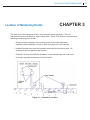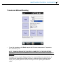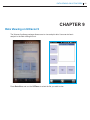
1
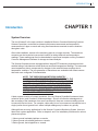
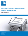
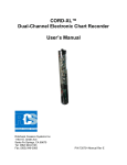
ULTRACORR®2 CORROSION MONITORING SYSTEM User Manual Rohrback Cosasco Systems, Inc. 11841 E. Smith Avenue Santa Fe Springs, CA 90670 Tel: (562) 949-0123 (800) 635-6898 Fax: (562) 949-3065 www.cosasco.com P/N:U-CORR2-MANUALrevC © 2012 Rohrback Cosasco Systems, Inc. All rights reserved. Ultracorr® is a trademark of Rohrback Cosasco Systems, Inc. Windows® is a trademark of Microsoft Corporation. Bluetooth® is a trademark of Bluetooth SIG, Inc. No part of this manual may be reproduced or transmitted in any form or by any means, electronic or mechanical, including photocopying and recording, for any purpose, without the express written permission of Rohrback Cosasco Systems, Inc. ULTRACORR®2 CORROSION MONITORING SYSTEM USER MANUAL Table of Contents Chapter 1 Introduction ............................................................................1 System Overview........................................................................................ 1 System Diagram........ ...................................................................................2 Major Components........................... ............................................................2 UST2 Transducer..............................................................................2 Signal Cabling...................................................................................3 Reading Point...................................................................................3 Ultracorr2 Instrument .......................................................................3 Smart Phone.....................................................................................4 Corrdata® II Software .................................................................4 Installation Toolkit..............................................................................4 Chapter 2 Specification ...........................................................................5 System........................................................................................................5 Ultracorr2 Instrument..................................................................................6 Chapter 3 Location of Monitoring Points ...........................................9 Chapter 4 Transducer Connection and Signal Cabling ................11 Cabling ......................................................................................................11 Local Mount Junction Box .......................................................................12 Chapter 5 Ultracorr2 Instrument ...........................................................15 Unpacking .................................................................................................15 Battery Installation ...................................................................................... 15 i ii TABLE OF CONTENTS Chapter 6 Smartphone.............................................................................17 Key Features..............................................................................................17 Smart Phone Software................................................................................18 Windows Vista/Windows 7..........................................................................18 Windows Mobile Device Center................................................................18 Windows XP...............................................................................................22 Microsoft ActiveSync..................................................................................22 Chapter 7 Smartphone/Ultracorr2 Configuration................................25 Smartphone & Ultracorr2 Communication..................................................25 Transducer Manual Reading....................................................................27 Transducer Saving.....................................................................................28 Ultracorr2 Test Mode..................................................................................28 Datalogger Mode.......................................................................................29 Registered Devices...................................................................................30 Transducer Calibration...............................................................................31 Chapter 8 Transfer Readings from Ultracorr2 to the Corrdata® II..................................................................33 Copying UC Files from SmartPhone to PC............................................33 Run Corrdata II.........................................................................................33 Chapter 9 Data Viewing on Ultracorr 2..................................................40 Appendix A Manufacturer’s Declaration of Conformity.........................43 CSA International (CSA) Certification .......................................................46 IEC Ex Certification - Ultracorr2 Ultrasonic Transmitter ...........................49 IEC Ex Certification - UST2 Ultrasonic Transducer ..................................54 ATEX Certification - Ultracorr2 Ultrasonic Transmitter ...................................58 ATEX Certification - UST2 Ultrasonic Transducer...........................................62 ULTRACORR®2 CORROSION MONITORING SYSTEM USER MANUAL Figures and Drawings Figure Page Figure 1.1 - System Overview......................................................................2 Figure 1.2 - UST2 Transducer (Typical)......................................................3 Figure 1.3 - Ultracorr2 Instrument...............................................................4 Figure 1.4 - Smartphone (Typical)...............................................................4 Figure 2.1 - Ultracorr2 Instrument Specifications...........................................7 Figure 3.1 - Transducer Location.................................................................9 Figure 4.1 - Weather Resistant Connector.................................................11 Figure 4.2 - Pole Mount Junction Box........................................................12 Figure 4.3 - Wall Mount Junction Box........................................................13 Figure 5.1 - Battery Cover of Ultracorr2 Instrument...................................16 iii iv TABLE OF CONTENTS INTRODUCTION CHAPTER 1 Introduction System Overview The new Ultracorr2 is the next evolution in handheld Ultracorr Corrosion Monitoring Systems. Ultracorr2 provides a cost effective ultrasonic thickness measurement and temperature measurement of a pipe or vessel wall using fixed transducers mounted at various locations throughout a site. After initial installation, access to the monitoring point is no longer required. The transducer connector can be located at a convenient location for taking thickness and temperature readings. These readings can then be downloaded to a personal computer running Corrdata II Corrosion Management Software for storage and trend analysis. The Ultracorr2 transducers are equipped with an integral RTD measuring temperature which enables taking of simultaneous metal thickness and metal temperature readings. The instrument uses temperature data to compensate for changes in the metal thickness readings due to temperature variations. The new generation of transducers are embedded with smart sensors that retain user configured ID characteristics. NOTE: THE CORROSION MONITORING INDUSTRY COMMONLY USES THE TERM “PROBE” TO REFER TO THE CORROSION MEASUREMENT SENSOR, WHICH COULD BE AN ULTRASONIC “PROBE”. IN THE NON-DESTRUCTIVE TESTING INDUSTRY, IT IS COMMON TO SEE THE TERM ULTRASONIC TRANSDUCER USED. FOR THE PURPOSES OF THIS MANUAL, THESE TERMS ARE EQUIVALENT AND MAY BE USED INTERCHANGEABLY. A basic system consists of a smart transducer, the new Ultracorr2 handheld instrument, data collection device, and Corrdata II Software package. Since it will often be advantageous to take a reading of the transducer from some remote point, there are numerous cabling options to connect these two items. For example, cables may be run from numerous transducers into a single junction box at ground level, where multiple readings may be taken very quickly. Although there are many applications for the Ultracorr Corrosion Monitoring System, there are three basic system applications. Refer to chapter 4 and 5 for installation procedures for various placement options. 1. Above ground insulated pipelines or vessels. 2. Above ground uninsulated pipelines or vessels. 3. Below ground, buried pipelines or vessels. 1 2 ULTRACORR®2 CORROSION MONITORING SYSTEM Figure 1.1 - System Overview System Diagram Figure 1.1 illustrates a typical installation of the Ultracorr2 Corrosion Monitoring System. The major components are described below. A UST2 Ultracorr Transducer B Signal Cabling C Reading Point D Ultracorr2 Instrument E Smartphone for control and data collection F PC Running Corrdata II Software Major Components UST2 Ultracorr Transducer The transducer (probe) is a small (1.2 inch diameter by 1.8 inch high) sensor which is permanently mounted to the monitoring point. This is accomplished using a special adhesive which also acts as an ultrasonic couplant. The transducer has a magnetic base to aid in holding it in position while the adhesive cures. The temperature sensor on the transducer allows for automatic correction of acoustic velocity as a result of the metal temperature. This provides a significantly more accurate reading of thickness. These newest generation transducers also have the capability of storing and transmitting location and configuration information to the Ulltracorr-2 instrument, for ease of operation and to eliminate operator errors. NOTE: PREVIOUS GENERATION TRANSDUCERS ARE COMPATIBLE, BUT NOT HAZARDOUS RATED FOR USE WITH THE ULTRACORR2. INTRODUCTION Figure 1.2 - UST2 Transducer (Typical) Signal Cabling Two types of cables are available to bring the reading point to a convenient location. For example, if a monitoring point is on a vessel 20 feet above the ground, then access to the monitoring point location is only required for the initial installation of the transducer. A cable may then be run from the transducer to a junction box located at ground level. Each installation must be evaluated for the proper type of cable installation. Standard cables have a weather resistant polyurethane jacket. Reading Point There are various options available for a remote reading site. For a location with a single monitoring point, the transducer cable is fitted with a weather resistant connector. An optional NEMA 4X junction box with provision for up to seven connectors is available. Larger junction boxes are also available. For underground applications, standard above ground or flush-withgrade monitoring locations are available. Ultracorr2 Instrument The Ultracorr2 instrument is the heart of the Ultracorr Corrosion Monitoring System. The intrinsically safe Class 1 Zone 1 rated, single Ultracorr2 instrument may be used to periodically take individual time and date stamped wall thickness, signal and temperature readings of up to 255 sensors. It will store up to 2000 readings for each of these sensors. Refer to Chapter 5 for more information. 3 4 ULTRACORR®2 CORROSION MONITORING SYSTEM Figure 1.3 - Ultracorr2 Instrument Smartphone The hazardous approved smart phone has two primary uses: One is to custom configure the Ultracorr2 Instrument which in turn will configure the UST2 smart transducer, and two is to allow for recent data from the Ultracorr2 Instrument to be collected from the Reading Point in the field. The smartphone has an easy to use application that interfaces with the Ultracorr2 instrument via Bluetooth communication. Once data has been saved onto the smart phone, the data can then be easily downloaded onto a PC for analysis with the Corrdata II Corrosion Management Software. Figure 1.4 - Smartphone (Typical) Corrdata II Software The Corrdata II Corrosion Management Software is a powerful application that can perform various functions. The software can be used to compare and analyze data with graphing tools, while also allowing for data to be converted into a CSV (comma separated value) format if exporting into a spreadsheet program. The Corrdata II software can also integrate other data process parameters such as CORROSOMETER and CORRATER instruments. Refer to Transfer Readings from Smart Phone to the Corrdata II section for more information on transferring and analyzing data on a personal computer. Installation Toolkit Toolkits containing all the tools for uncoated and coated pipeline installations are available, or tools may be ordered on an individual basis. The toolkits contains such items as a cordless drill with a spare battery and charger, tools for paint removal and surface preparation, and the required epoxy to attach the transducer to the pipeline. Please contact RCS for further details. SPECIFICATIONS CHAPTER 2 Specifications Ultracorr2 Instrument Battery Requirements: 2 x 3.6V AA Lithium Cells (RCS P/N 095820) Battery Life: Over 6000 readings Operating Temperature: -40°F to 158°F (-40°C to 70°C) Storing Temperature: -40°F to 158°F (-40°C to 70°C) Dimensions: 6”H x 3.25”W x 1.25”D (152.4 mm x 82.55 mm x 31.75 mm) Weight: 1 lb. ( 0.45 kg ) Intrinsic Safety rated for USA, Canada, and Europe: For USA/Canada: Ex ib IIC T4: Class I, Zone 1 AEx ib IIC T4 For Europe: II 2G Ex ib IIC T4 Gb Ta = -40°C to +70°C UST2 Ultrasonic Sensor Thickness Measurement: Range: 0.2 (0.1 for special orders) to 2.0 inches, up to 25 ft. cable Resolution: 0.0001 inch Accuracy: ± 0.0002 inch at constant temperature ± 0.0005 inch from -40°C to +70°C (Instrument) ± 0.0003 inch from -40°C to +150°C (Metal Surface of Transducer) 5 6 ULTRACORR®2 CORROSION MONITORING SYSTEM Transducer Temperature: Range: Ambient: -40°F to +158°F (-40°C to +70°C) Metal Surface: -40°F to +305°F (-40°C to +150°C) Temperature Compensation: -0.0002 inch/inch/°C Temperature Differential Error: -0.0001 inch/inch/°C difference (inside to outside of wall) Temperature Measurement: Range: -40°C to +150°C Resolution: 0.1°C Accuracy: ±2°C (Transducer) ±2°C (Instrument) Data Storage: Memory Type: Probes: Readings/Probes: Nonvolatile 255 2000 Time and Date Stamped Interface: Bluetooth® Transducer Type: Contact Transducer Cable: RG-174 up to 25 ft. Hardware Supplied: Ultracorr2 Instrument 2 AA Lithium batteries CD-ROM or Flash Drive Software Supplied: Ultracorr2 Corrosion Monitoring System User Manual Window XP/Window7/Windows Drivers Corrdata II Corrosion Management Software SPECIFICATIONS 6” 3.25” 1.25” Figure 2.1 Ultracorr2 Instrument Specifications 7 8 ULTRACORR®2 CORROSION MONITORING SYSTEM LOCATION OF MONITORING POINTS Location of Monitoring Points CHAPTER 3 The small size of the transducer allows it to be mounted almost anywhere. The only requirement is a two inch diameter area of clean metal. Some of the factors to consider when selecting a monitoring point include: • Access must be provided to the monitoring point for the initial transducer installation. After installation, access to the monitoring point is not required. • Insulated vessels must have the insulation removed at the monitoring point. An access port can be installed at that location. • Generally, the most cost effective installation is the shortest cable run to the most convenient and safe man access to the test station. Figure 3.1 - Transducer Location 9 10 ULTRACORR®2 CORROSION MONITORING SYSTEM TRANSDUCER CONNECTION AND SIGNAL CABLING Transducer Connection and Signal Cabling 11 CHAPTER 4 Cabling The standard transducer is fitted with a weather resistant connector (see figure 4.1). This connector is suitable for outdoor environments, and therefore can be left at a convenient reading point without any further protection. If required, cable can be run through conduit to its desired location. Conduit must be 1-1/4” or larger, to accommodate the 1.25” diameter connector housing. Two types of cable are available. The standard has a thick, black polyurethane outer jacket, and is suitable for most environments. For more severe applications, this same cable is available with a braided, stainless steel armor jacket. Figure 4.1 - Weather Resistant Connector 12 ULTRACORR®2 CORROSION MONITORING SYSTEM Local Mount Junction Box An alternative to leaving the connector exposed is to mount one or more connectors inside a NEMA 4X box. There are several advantages to doing this, including additional protection, security, and the ability to run multiple connections to a single point for rapid measurements. Two standard box configurations are available. RCS part number 744014 is designed to mount on a two inch pipe and has provisions for up to 7 transducer connectors (see figure 4.2). This configuration is particularly suitable for buried pipeline applications, as the cables can be run from the buried pipe, through the 2” supporting pipe and into the box. Figure 4.2 - Pole Mount Junction Box TRANSDUCER CONNECTION AND SIGNAL CABLING RCS part number 744017 is the same size box, but is configured for the transducer connectors to mount on the bottom of the box. Mounting ears are provided on the box for wall or pole mounting. This box may be more suitable for above ground transducer applications (see figure 4.3). Figure 4.3 - Wall Mount Junction Box 13 14 ULTRACORR®2 CORROSION MONITORING SYSTEM ULTRACORR®2 INSTRUMENT Ultracorr®2 Instrument 15 CHAPTER 5 The intrinsically safe, Class I, Zone I rated Ultracorr2 utilizes high sensitivity ultrasonic technology to provide nonintrusive, cost effective monitoring of corrosion and erosion. The instrument can be used to provide periodic time and date stamped measurements of wall thickness and temperature of up-to 50 transducers. The thickness and temperature data can then be downloaded to a personal computer running Corrdata II Corrosion Management Software for storage and trend analysis. NOTE: EACH ULTRACORR2 INSTRUMENT IS CAREFULLY TESTED, INSPECTED AND PACKAGED PRIOR TO SHIPMENT. BEFORE UNPACKING THE INSTRUMENT, PLEASE INSPECT THE PACKAGED MATERIALS FOR SHIPPING DAMAGE AND RETAIN ALL DAMAGED PACKAGED MATERIALS TO SUPPORT ANY CLAIM AGAINST YOUR FREIGHT CARRIER SHOULD THIS BECOME NECESSARY. Unpacking Carefully remove the instrument from its package. Included in the package you should find: • Handheld Ultracorr2 instrument • USB with Ultracorr2 Corrosion Monitoring System User Manual, and Corrdata II Corrosion Management Software and User Manual • 2 AA Lithium batteries Battery Installation The Ultracorr2 is supplied with a set of two 3.6 Volt lithium batteries (RCS PN 095820). To install these batteries, remove the access panel on the back of the unit (see below) and install the batteries with the polarities as indicated on the unit. Replace the back cover when finished. 16 ULTRACORR-2 CORROSION MONITORING SYSTEM Figure 5.1 - Battery Cover of Ultracorr2 Instrument SMARTPHONE CHAPTER 6 Smartphone The Smartphone is the essential wireless shuttle that will allow the Ultracorr2 Instrument to transmit all relevant information from the UST2 probes in the field on to a PC. The Smartphone is more unique than your average multi-band phone. It’s rugged makeup can be operated in explosion hazardous areas rated up to Class I, Zone 2, or Class I, Zone I for North American certified smart phones. The phone is also Dustproof and Waterproof with an IP 65 rating. The phone has the capabilities of using various Microsoft Windows applications because of its Windows Mobile 6.5 Operating System. The Smartphone is user friendly and allows a user to use Bluetooth to download and store a large amount of data quickly from many UST2 locations and transfer all your data back to a PC via micro USB cable or Bluetooth. NOTE: PHONE MODEL MAY VARY DEPENDING ON LOCATION OF USE AND HAZARDOUS REQUIREMENTS Key Features • • • • • • 17 UL/CSA Class I, Zone I and Zone 2 (for North America) ATEX Hazardous Rated Class I, Zone 2 Dustproof and Waterproof (IP 65) Touch Screen GPS/Wi-Fi/Bluetooth Compatible with Windows XP/Windows Vista/Windows 7 18 ULTRACORR®2 CORROSION MONITORING SYSTEM Smartphone Software In many cases, the following steps will not be needed to begin functioning the Smartphone with the Ultracorr2 system because the phone will likely be pre-configured by Rohrback Cosasco Systems for the customer to turn on and begin use. In the event that a smartphone needs to be restored with a fresh installation of Ultracorr2 software, the following instructions will guide you through proper software installation. The main thing to consider is which operating system you will be running in order to properly run the appropriate software. Please note, some windows geniune authentication may be required in order to run the installation software. Windows Vista/Windows 7/ Windows 8 For systems using Windows Vista/7, likely Windows Mobile Device Center will be included within the operating system and everything should run seamlessly once your smartphone is connected to the PC. If not, files have been provided on an RCS USB Flash drive to install the appropriate drivers for the operating system you use. Windows Mobile Device Center The following screens will guide you through proper installation: Connect without setting up your device 19 Browse the content of your device Explore directory \My Documents\Personal\UC Copy the Ultracorr2 distribution package from the RCS Flash Drive into this directory 20 ULTRACORR®2 CORROSION MONITORING SYSTEM Start the Explorer on the mobile computer and navigate to My Documents\Personal and Click Installation file “UC2Setup to begin Installation. 21 Once installation is complete, the RCS Ultracorr2 icon will appear in the file explorer. 22 ULTRACORR®2 CORROSION MONITORING SYSTEM Windows XP For Windows XP users, there is a two step process to accessing the phone file explorer and running the Ultracorr2 software. Step one, install the provided Microsoft Activesync software on to the PC. Step two, plug in your phone via USB cable and allow for Activesync to detect and install the appropriate drivers. Microsoft ActiveSync The following screens will guide you through the installation process: 23 Once ActiveSync has been completely installed, connect the Smartphone to the PC and wait for ActiveSync to install the appropriate drivers. The phone should automatically be detected, and steps should be repeated from pages 19-21, in order to have Ultracorr2 functional on the Smartphone. 24 ULTRACORR®2 CORROSION MONITORING SYSTEM SMARTPHONE/ULTRACORR®2 CONFIGURATION Smartphone/Ultracorr-2 Configuration 25 CHAPTER 7 This chapter covers the various steps involved in Ultracorr2 communications and functionality testing. In order to successfully test the instrument, the Smartphone must be charged with bluetooth active and Ultracorr2 software installed. Also, the UST2 probe must be connected to the Ultracorr2 Instrument. Smartphone & Ultracorr2 Communication NOTE: PROBE TO ULTRACORR2 MUST BE CONNECTED! • Run the Ultracorr 2 application on your Windows Mobile Smartphone. • Click the Search button to search for a device that’s in range and wait 10 seconds. If a device is not found but connected correctly, search again before attempting to do further troubleshooting. 26 ULTRACORR®2 CORROSION MONITORING SYSTEM • Connect to Device and pairing will begin automatically. The pairing will retrieve all relevant information from the smart transducer which is connected to the Ultracorr2. • The standard RCS configurations read from the transducer are Tag name, ID, and Alloy type.Once a configuration is changed, you MUST click Menu and Write Configuration to save. To edit Tag or ID fields, click the T9 icon to activate the virtual keyboard. Note: Keyboard and OK buttons on bottom menu are Windows Mobile buttons! SMARTPHONE/ULTRACORR®2 CONFIGURATION Transducer Manual Reading • To read the transducer, click Read to acquire the Thickness measurement, Temperature, Gain, and Battery level. NOTE: TRANSDUCER MUST BE PROPERLY CONNECTED TO THE PIPE BEFORE READING THE PROBE, THE BETTER THE CONNECTION, THE MORE ACCURATE THE READING! • Readings that have a higher dB gain will have less accurate thickness measurements. As a rule of thumb, anything above 40dB should be re-calibrated. Ways of getting a better reading are by sanding down the surface of the pipe more or adjusting the transducer mating. 27 28 ULTRACORR®2 CORROSION MONITORING SYSTEM Transducer Saving • To save a reading, click the Save button to save the most recent reading of that probe. • To do continuous testing, click the Test button to continuously take measurements every second. Ultracorr2 Test Mode SMARTPHONE/ULTRACORR®2 CONFIGURATION Datalogger Mode • Click Logger to access Datalogger Mode. Click Data to Download all the data to the Phone. • Type “00” to disable Logger. To enable Logger, enter a value between 10-1440 minutes and click Store. To erase all data, click Menu, Erase Logger.. 29 30 ULTRACORR®2 CORROSION MONITORING SYSTEM Registered Devices The Ultracorr 2 software allows users to register or unregister an Ultracorr 2 device. This tool allows for by passing the search command and directly connecting to a known device. Registering New Device: Simply click on “Add Device” to add a new device after it has been discovered. The new addition will be permenantly stored on the phone. Unregistering Device: Simply click on the “Remove Device” button to remove from the preferred device list. Once a device is registered, the application can connect to an Ultracorr 2 instrument directly. SMARTPHONE/ULTRACORR®2 CONFIGURATION Transducer Calibration Transducers are pre-calibrated before being shipped to a customer. NOTE: DO NOT attempt to calibrate a transducer without notifying RCS. In most cases your transducer will not require a field calibration. If transducer calibration is required, please contact your closest RCS regional office location for assistance. Information on the latest software version will be required. • To confirm the latest software revision press Menu>About 31 32 ULTRACORR®2 CORROSION MONITORING SYSTEM • To Access the transducer’s calibration parameters press Menu > Calibration To contact RCS technical support go to: [email protected] or call toll free 1-800-635-6898 TRANSFER READINGS FROM ULTRACORR-2 TO THE CORRDATA II Transfer Readings from Ultracorr®2 to the CORRDATA II CHAPTER 8 The most recent reading for any probe may be displayed on the Ultracorr2 Smartphone. For maximum functionality and data management, all the data contained in the smartphone may be downloaded to a personal computer running Corrdata II Corrosion Management Software package. The Corrdata II package is a flexible corrosion data management system that allows integration of all corrosion monitoring parameters. Refer to the Corrdata II Corrosion Management Software documentation for installation, site setup, capabilities and other details. Copying UC Files from SmartPhone to PC Once phone is connected to PC, browse the phone and copy the My Documents\Personal\UC directory to a known location on the local PC hard drive. This will avoid possible data corruption when importing from the PC, rather than directly from the SmartPhone. Run Corrdata II After a database has been created, click on Equipment Layout + Selection Tool Icon. Follow instructions below to add the Ultracorr2 Points. 1. 2. 3. 4. 33 Click Item Palette Icon to add Instument Add System by dragging System Icon onto Equipment Layout. (Adding offline subsystem is optional. Add Device by dragging Device Icon onto System Select Mate then click on Ultracorr2 as shown below 34 ULTRACORR®2 CORROSION MONITORING SYSTEM 5. Ultracorr2 Phone will be displayed. Highlight Ultracorr 2 phone and click on green downwards arrow Icon that allows to Import Ultracorr2 Data. 6. Once browsing import, the directory should be browsed to your local drive where files have been copied and not from the SmartPhone. TRANSFER READINGS FROM ULTRACORR®2 TO THE CORRDATA II 35 36 ULTRACORR®2 CORROSION MONITORING SYSTEM 7. Select the file ID that correctly matches the created point and click Open. TRANSFER READINGS FROM ULTRACORR®2 TO THE CORRDATA II 8. Transducer data should now be imported successfully 37 38 ULTRACORR®2 CORROSION MONITORING SYSTEM 9. Right-click on probe, once data has been imported to verify ID, Tag and Alloy are correct. 10. Drag the Probe from the Equipment Layout to the Selection Tool. The parameters should be copied into the Selection Tool allowing for graphing. of Data. TRANSFER READINGS FROM ULTRACORR®2 TO THE CORRDATA II 11. The parameters can be overlayed or plotted individually. 12. Right-clicking on probe and selecting Data Entry (Manual) will allow you to see the raw data. Load Data must be clicked to refresh data from database. 39 40 ULTRACORR®2 CORROSION MONITORING SYSTEM DATA VIEWING ON ULTRACORR2 41 CHAPTER 9 Data Viewing on Ultracorr2 The Ultracorr2 software package allows users to view and plot data. Users can do basic analysis in the field utilizing this tool. Press Data View, and use the UP/Down to select the file you wish to view 42 ULTRACORR®2 CORROSION MONITORING SYSTEM Graph View Click and drag around the area you want to zoom in Table View On table view mode the data is arranged by date (Month/day/Year), time and thickness (inches) MANUFACTURER’S DECLARATION OF CONFORMITY Manufacturer’s Declaration of Conformity 43 APPENDIX A Product Name: ULTRACORR2 Ultrasonic Transmitter Model: ULTRACORR2 Approved Manufacturing Location Rohrback Cosasco Systems, Inc. — Santa Fe Springs, California USA European Union (EU) Directives ATEX Certification Sira 12ATEX2083X II 2G Ex ib IIC T4 Gb Ta = -40°C to +70°C For use only with AA Lithium cells: P/N 095818 ATEX Directive 94/9/EC The ULTRACORR2 complies with the European ATEX Directive and the following standards: IEC 60079-0:2011 Ed. 6, Electrical Apparatus for Explosive Gas Atmospheres - Part 0: General Requirements EC 60079-11:2011-06 Ed. 6, Electrical Apparatus for Explosive Gas Atmospheres - Part 11: Intrinsic Safety “ i ” The ULTRACORR2 complies with the European EMC Directive and the following standards: EN 61326:2006, Electrical Equipment for Measurement and Control EN 61000-4-2:2008, EMC: Electrostatic Discharge Immunity EN 61000-4-3:2006, A1:2008, EMC: Radiated Radio Frequency Immunity EN 61000-4-4:2004, Electrical Fast Transient Immunity EN 61000-4-6:2004, Conducted RF Immunity EN55011:2009, A1:2010 (CISPR 11:2009, A1:2010), EMC, Industrial, scientific and medical devices – Limits and methods of measurement. 44 ULTRACORR®2 CORROSION MONITORING SYSTEM IEC Ex Certification Sira IECEx SIR 12.0028X Ex ib IIC T4 Gb Ta = -40°C to +70°C For use only with AA Lithium cells: P/N 095818 The ULTRACORR2 complies with the following IEC standards: IEC 60079-0:2011 Ed. 6, Electrical Apparatus for Explosive Atmospheres - Part 0: General Requirements EC 60079-11:2011-06 Ed. 6, Electrical Apparatus for Explosive Atmospheres - Part 11: Equipment protection by Intrinsic Safety “ i ” CSA International (CSA) Certification The ULTRACORR2 has been examined and tested to determine that the design meets basic electrical, mechanical and fire protection requirements by CSA, a Nationally Recognized Testing Laboratory (NRTL) as accredited by the Federal Occupational Safety and Health Administration (OSHA). North American Certifications Ex ib IIC T4: Class I, Zone 1 AEx ib IIC T4 For use only with AA Lithium cells: P/N 095818 The ULTRACORR2 complies with the following North American standards: CSA C22.2 No. 0-10, General Requirements – Canadian Electrical Code, Part II CAN/CSA-C22.2 No. 60079-0:11, Explosive atmospheres — Part 0: Equipment — General requirements CAN/CSA-C22.2 No. 60079-11:11, Explosive atmospheres — Part 11: Equipment protection by intrinsic safety “i” ANSI/ISA-60079-0 (12.00.01)-2009, Electrical Apparatus for Explosive Gas Atmospheres Part 0: General Requirements ANSI/ISA-60079-11 (12.02.01)-2011, Electrical apparatus for Explosive Gas Atmospheres Part 11: Intrinsic Safety “i” Federal Communications Commission (FCC) and Industry Canada (IC) This device complies with Part 15 of the FCC Rules. Operation is subject to the following conditions: This device may not cause harmful interference. This device must accept any interference received, including interference that may cause undesired operation. This device must be installed to ensure a minimum antenna separation of 20 cm from all persons. MANUFACTURER’S DECLARATION OF CONFORMITY Telecommunication Compliance All wireless devices require certification to ensure that they adhere to regulations regarding the use of the radio frequency (RF) spectrum. Nearly every country requires this type of product certification. RCS is working with governmental agencies around the world to supply fully compliant products and to remove the risk of violating country directives or laws governing wireless device usage. Place and Date of Issue: October 17, 2012 RohrbackCosasco Systems, Inc. Santa Fe Springs, CA 90670 Authorized Signature: Steven L. Stricklin Quality Assurance Manager 45 46 ULTRACORR®2 CORROSION MONITORING SYSTEM MANUFACTURER’S DECLARATION OF CONFORMITY 47 48 ULTRACORR®2 CORROSION MONITORING SYSTEM MANUFACTURER’S DECLARATION OF CONFORMITY IEC Ex Certification - Ultracorr2 Ultrasonic Transmitter 49 50 ULTRACORR®2 CORROSION MONITORING SYSTEM MANUFACTURER’S DECLARATION OF CONFORMITY 51 52 ULTRACORR®2 CORROSION MONITORING SYSTEM MANUFACTURER’S DECLARATION OF CONFORMITY 53 54 ULTRACORR®2 CORROSION MONITORING SYSTEM IEC Ex Certification - UST2 Ultrasonic Transducer MANUFACTURER’S DECLARATION OF CONFORMITY 55 56 ULTRACORR®2 CORROSION MONITORING SYSTEM MANUFACTURER’S DECLARATION OF CONFORMITY 57 58 ULTRACORR®2 CORROSION MONITORING SYSTEM ATEX Certification - Ultracorr2 Ultrasonic Transmitter MANUFACTURER’S DECLARATION OF CONFORMITY 59 60 ULTRACORR®2 CORROSION MONITORING SYSTEM MANUFACTURER’S DECLARATION OF CONFORMITY 61 62 ULTRACORR®2 CORROSION MONITORING SYSTEM ATEX Certification - UST2 Ultrasonic Transducer MANUFACTURER’S DECLARATION OF CONFORMITY 63 64 ULTRACORR®2 CORROSION MONITORING SYSTEM MANUFACTURER’S DECLARATION OF CONFORMITY 65 66 ULTRACORR®2 CORROSION MONITORING SYSTEM