1
RC-12BP
User´s Manual
PN 77203 - 2
OPERATING
INSTRUCTIONS
SORVALL RC12 BP
®
TM
High-Capacity
Lowspeed
Refrigerated
Centrifuge
Thermo Scientific
Asheville, North Carolina
U.S.A.
PN 77203-2
Issued February 2007
SORVALL® Centrifuges
Table of Contents
This manual is a guide to the use of the
SORVALL® RC12BP
High-Capacity Lowspeed Refrigerated Centrifuge
Information herein has been verified and is believed adequate for the intended use of the centrifuge.
Because failure to follow the recommendations set forth in this manual could produce personal injury
or property damage, always follow the recommendations set forth herein. Thermo Scientific
does not guarantee results and assumes no obligation for the performance of centrifuges
or other products that are not used in accordance with the instructions provided. This publication is
not a license to operate under, nor a recommendation to infringe upon, any process patents.
Publications prior to the Issue Date of this manual may not contain data in apparent conflict with that
provided herein. Please consider all data in this manual to be the most current.
WARNING, CAUTION, and NOTE within the text of this manual are used to emphasize
important and critical instructions.
WARNING informs the operator of a hazard or an unsafe practice that could result in
personal injury, affect the operator’s health, or contaminate the environment.
CAUTION informs the operator of an unsafe practice that could result in damage of
equipment.
NOTE highlights essential information.
WARNING and CAUTION are accompanied by a hazard symbol
sidebar near the information they correspond to.
!
and appear in the left
IBM is a registered trademark of International Business Machines Corporation; Pentium is a
registered trademark of Intel Corporation; Microsoft, MS, DOS, Windows, Windows 95, and
Windows NT are registered trademarks of Microsoft Corporation.
© 1998, 1999 by Thermo Scientific
ii
RC12BP™
Table of Contents
Important Safety Information
Certain potentially dangerous conditions are inherent to the use of all centrifuges. To ensure safe operation
of this centrifuge, anyone using it should be aware of all safe practices and take all precautions described below
and throughout this manual.
!
WARNING
When using radioactive, toxic, or pathogenic materials, be aware of all characteristics of the materials and the hazards
associated with them in the event leakage occurs during centrifugation. If leakage does occur, neither the centrifuge nor
the rotor can protect you from particles dispersed in the air. To protect yourself, we recommend additional precautions be
taken to prevent exposure to these materials, e.g., use of controlled ventilation or isolation areas.
Always be aware of the possibility of contamination when using radioactive, toxic, or pathogenic materials. Take all
necessary precautions and use appropriate decontamination procedures if exposure occurs.
In the future, if biocontainment products are added, the use of sealed rotors, buckets, and/or sample containers will
offer increased protection from contamination during routine operation. However, these items will not guarantee
protection from accidents resulting from damage to the rotor or buckets. Do run hazardous materials in the centrifuge
unless placed in a biohazard enclosed and operated using all appropriate safety precautions.
Never use any materials capable of producing flammable or explosive vapors, or creating extreme exothermic reactions.
Use SORVALL® rotors only. Use of another manufacturer's rotor can cause rotor failure which could result in personal
injury or centrifuge damage.
Never exceed the maximum rated speed of the installed rotor; to do so can cause rotor failure.
Always reduce (derate) rotor speed as instructed in this manual whenever:
• the rotor speed/temperature combination exceeds the solubility of the gradient material and causes it to precipitate.
• the compartment load exceeds the maximum allowable compartment load specified. See Chapter 4, page 4-14.
Failure to reduce rotor speed under these conditions can cause rotor failure.
Centrifuges routinely deal with high energy levels and could move suddenly in the unlikely event of rotor failure.
During centrifuge operation, never lean on or move the centrifuge, keep the surrounding area clear of objects (including
all hazardous materials), and do not work on top of or next to the centrifuge.
Do not attempt to open the chamber door when the rotor is spinning; never override or otherwise disable any of the
safety systems of the centrifuge.
!
CAUTION
Do not run or precool/preheat a rotor at the critical speed, as this will have a detrimental effect on centrifuge component
life. See Chapter 4, Rotor Temperature Equilibration, page 4-13.
Do not operate the centrifuge with a rotor out of balance. To do so can cause damage to the centrifuge drive assembly.
Do not operate centrifuge without a rotor properly installed and locked to the drive, and the rotor cover (if any) must
be properly installed. See rotor instruction manual.
Locate the centrifuge on a level floor to avoid rotor imbalance during operation.
The centrifuge can be damaged if connected to the wrong voltage. Check the voltage before plugging the centrifuge
into a power source. Thermo is not responsible for incorrect installation.
Always maintain the centrifuge in the recommended manner. See Chapter 5, Maintenance.
iii
SORVALL® Centrifuges
Table of Contents
Table of Contents
Page
Safety Information Page
iii
Chapter 1. INTRODUCTION & DESCRIPTION
Centrifuge Description .............................................................. 1-1
Centrifuge Specifications .......................................................... 1-4
Parts Supplied ............................................................................ 1-5
Optional Computer Interface Package ...................................... 1-6
Chapter 2. INSTALLATION
Inspection .................................................................................. 2-1
Electrical Requirements ............................................................ 2-1
Location ..................................................................................... 2-2
Installation ................................................................................. 2-3
Chapter 3. CONTROLS, INDICATORS,
and DISPLAYS
RUN Display .................................................................................... 3-2
SET Display .............................................................................. 3-3
HOME Screen ...................................................................... 3-3
Main POWER and KEYPAD LOCK ........................................ 3-4
Primary Function Keys and HOME Screen Fields ................... 3-5
MENU Key and OPTIONS ....................................................... 3-8
Numeric Keypad ........................................................................ 3-12
START and STOP Keys ............................................................ 3-13
SET Display Advisory Messages .............................................. 3-14
Problem Conditions .............................................................. 3-14
Terminal Conditions ............................................................. 3-18
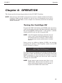
Chapter 4. OPERATION
Turning the Centrifuge ON ....................................................... 4-1
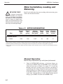
Rotor Installation, Loading, and Balancing .............................. 4-2
Normal Operation ...................................................................... 4-2
Programmed Operation ............................................................. 4-4
Using Advanced Features (Options) .......................................... 4-6
Temperature Control ................................................................. 4-12
Rotor Temperature Equilibration .............................................. 4-13
iv
RC12BP™
Table of Contents
Page
Running Hazardous Material..................................................... 4-14
Reducing Speed for Rotor Compartment Loads
in Excess of Design Mass ..................................................... 4-14
Chapter 5. MAINTENANCE
Inspection and Cleaning ............................................................ 5-1
Lubrication ................................................................................ 5-2
Customer Control Inspection .................................................... 5-3
Emergency Sample Recovery .................................................... 5-5
Parts Ordering Information ....................................................... 5-6
Service Decontamination Policy ............................................... 5-7
APPENDIX
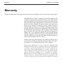
Warranty
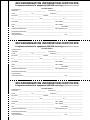
Decontamination Certificates
List of Illustrations
Figure
1-1.
2-1.
2-2.
2-3.
3-1.
4-1.
5-2.
Page
Parts Location and Identification ................................. 1-2
RC12BP™ Electrical Requirements ............................ 2-2
Centrifuge Dimensions................................................. 2-3
Front Locking Stabilizer Adjustment ........................... 2-4
Control Panel and Displays .......................................... 3-1
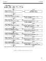
Advanced Feature Option Screens ............................... 4-7
Location of Mechanical Door Override ....................... 5-5
List of Tables
Table
Page
4-1.
Rotor Information ........................................................ 4-2
v
v/vi
Introduction & Description
SORVALL® Centrifuges
RC12BP™
Introduction & Description
Chapter 1: INTRODUCTION & DESCRIPTION
This manual contains information required to operate and maintain the SORVALL® RC12BP™ HighCapacity Lowspeed Refrigerated Centrifuge. If you require additional information regarding operation or
maintenance, please contact Thermo for assistance. In the United States, call toll-free 1-800-522-7746.
Outside the United States, contact your local representative for SORVALL® products.
Centrifuge Description
The SORVALL® RC12BP™ is a microprocessor controlled, highcapacity lowspeed refrigerated centrifuge designed for use in regulated environments (such as those found in blood banking, biotechnology, or pharmaceutical arenas). The control panel, designed to be
easy to use and easy to clean, allows simple input through a positivefeedback keypad with visual verification of set parameters and current
run conditions. The control panel also prompts users for correct entry
and displays user messages. The control panel introduces automation
of quality control runs, an optional computer interface package
enables automatic, on-line, quality control run and production run
data logging.
The RC12BP™ operates at speeds* up to 4700 rpm, and is capable of
producing relative centrifugal force up to 7333g. It uses a balanced,
high-torque brushless dc motor designed to deliver optimal
performance with smooth, quiet operation over its full speed range,
with long bearing life. Advanced capabilities of this motor offer
precise control of acceleration and deceleration, regardless of rotor
load, for exceptional run reproducibility. Directly connected to the
motor is a heavy-duty gyro-action drive with a square spindle that
accepts the SORVALL® H-12000 high-capacity swinging bucket
rotor. A viewing port in the chamber door permits speed confirmation
using an optical tachometer.
Precise temperature control is made possible by a refrigeration system
that is capable of delivering both cooling and heating. The highcapacity system is charged with environmentally-friendly CFC-free
refrigerant. The microprocessor-controlled system consists of a lowtemperature evaporator, a hermetically-sealed thermally-protected
compressor, and a fan-cooled finned condenser.
* Speed in revolutions per minute (rpm) is related to angular velocity, ω, according to the following:
ω = (rpm)
( )
2π
= (rpm) (0.10472)
60
Where ω = rad/s. All further references in this manual to speed will be designated as rpm.
1-1
SORVALL® Centrifuges
Introduction & Description
The RC12BP™ has the following safety features: a protective armor
plate steel guard within the cabinet; automatic shutoff of the drive
motor for overspeed protection; circuit breakers on the main power
and the control panel circuits; and a door interlock which prevents
starting the drive while the chamber door is open, or opening the door
while the rotor is in motion.
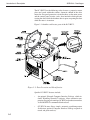
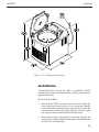
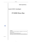
Figure 1-1 identifies and locates parts of the RC12BP™.
Figure 1-1. Parts Location and Identification
Specific RC12BP™ features include:
1-2
•
An optional Network Computer Interface Package, which includes WatchLog Network™ software, allows automatic computerized logging of centrifuge QC RUN and production run data
via RS485/RS232 communication hardware.
•
QC RUN feature allows simple, automatic speed/temperature
verification (optional Computer Interface Package required to
record and print run data).
RC12BP™
Introduction & Description
•
A user-friendly, easy to clean control panel with an interactive
backlit LCD SET display that prompts appropriate input and
displays advisory messages, option selection indicators, and a
separate, large LED RUN display for across-the-room viewing.
•
Programming capability allows saving (to a battery backed-up
memory) up to 9 sets of run parameters plus 6 step run sequences, allowing simple recall and error-free run reproducibility. The SAVE RUN sequence alerts users before overwriting
programs, to eliminate inadvertent loss. A convenient RECALL
key allows access to saved parameters for selection or reference.
•
STEP RUN capability allows the linking-together of up to three
sets of run parameters to automatically perform innovative step
run protocols. The step run sequences may be saved in program
memory for future use.
•
KEYPAD LOCK, a 3-position keyswitch with a removable key,
that is designed to limit control panel access. Besides allowing
full functionality, the keyswitch can be set so that run parameters
cannot be changed, or so that only parameters from saved
programs may be run – in either case, greatly reducing the chance
for operator error or unauthorized changes.
•
Run duration controlled by TIME (minutes:seconds), by HOLD
(for continuous runs), or by Accumulated Centrifugal Effect™
(ACE). Because rotor load differences, fluctuations in voltage, or
slight mechanical differences affect how quickly centrifuges
reach set speed, ACE calculates the effect of speed in relation to
time, and adjusts run duration to account for differences in
acceleration, thereby improving separation consistency and run
reproducibility – run after run, from centrifuge to centrifuge.
•
Rotor SPEED controlled by RPM (revolutions per minute), or by
the RCF (relative centrifugal force, or g-force).
•
SLOW START chooses gentle acceleration from 0 to 250 rpm (at
250 rpm, acceleration transitions to the normal, maximum rate),
with the slow start rate defined by the selection of one of ten
different acceleration profiles.
•
SLOW STOP chooses gentle deceleration from 500 to 0 rpm
(normal braking from set speed transitions to a more gradual rate
at 500 rpm), with the rate defined by selection of one of ten
different braking profiles.
1-3
SORVALL® Centrifuges
Introduction & Description
NOTE Selecting BRAKE OFF will affect SLOW STOP.
•
BRAKE OFF deactivates normal braking for a coasting stop
from a user-specified transition speed.
•
Automatic sample temperature calculation considers the run
speed, run time, set temperature and measured chamber temperature to estimate and maintain sample temperature.
•
Automatic self-test performed by the microcomputer each time
the centrifuge power is turned on, to ensure proper performance.
•
Automatic diagnostics, so that if a system malfunction occurs, a
message appears in the SET display to alert you of the condition.
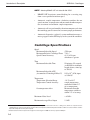
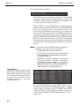
Centrifuge Specifications
Speed
Maximum Selectable Speed
4700 rpm
Maximum Relative Centrifugal Force 7333 g
Speed Control Accuracy
±1% or 20 rpm,
whichever is greater
Time
Maximum Selectable Time
Maximum Selectable ACE
(Accumulated Centrifugal Effect™)
Temperature
Temperature Selection Range
Temperature Control Accuracy
Overtemperature Alert
99 minutes, 99 seconds
(or HOLD for indefinite
length of time, timed up
to 300:00)
9.99 x 1030 (∫ω2dt, input
as 9.99e30)
–10°C to 40°C
sample temperature
controlled within 2°C
of set temperature*
Maximum allowable
temperature settable to
within 2°C of set temp
Maximum Noise Level
< 65 dB**
Maximum Average Heat Output
5.3 kW
* With sample, rotor, and chamber temperatures equal to SET temperature at the start of the run, or, during a run, after those components reach
equilibrium. Control range is reduced if run speed/ run time/set temperature/ambient temperature variables combine to create an extreme condition
beyond the temperature control system capacity.
** Measured 3 feet from the front panel at a height of four feet using an H-12000 rotor at its top speed of 4700 rpm.
1-4
RC12BP™
Introduction & Description
Weight (uncrated, without rotor)
Dimensions
Width
Depth
Height, top of control console
Length, power cord (minimum)
Other
Depth, back of door to back panel
Height, top of open door
Height, rotor installation lift-over
Diameter, chamber opening
Supply Power Requirements
Supply Configurations (AC)
Recommended Supply Current
Single Phase
Polyphase
Supply Power Receptacle
Standard
230 V, 50 Hz, 1Ø
230 V, 50 Hz, 3Ø
517 kg (1139 lb)
83.8 cm (33 inch)
106.7 cm (42 inch)
112.8 cm (44.4 inch)
244 cm (96 inch)
21.8 cm (8.6 inch)
170.4 cm (67.1 inch)
90.2 cm (35.5 inch)
66.8 cm (26.3 inch)
200 V, 60 Hz, 1Ø
208 V, 60 Hz, 1Ø
220 V, 60 Hz, 1Ø
230 V, 60 Hz, 1Ø
240 V, 60 Hz, 1Ø
200 V, 50 Hz, 1Ø
220 V, 50 Hz, 1Ø
230 V, 50 Hz, 1Ø (CE)
230 V, 50 Hz, 3Ø (CE)
240 V, 50 Hz, 1Ø
50 A
32 A/phase
NEMA 6-50R
CEE-17 (63A, 2-pole
and earth, 1Ø)
CEE-17 (32A, 3-pole
neutral and earth, 3Ø)
Parts Supplied
Parts supplied with your RC12BP™ Centrifuge include:
77203
77204
56418
68025
22001
Operating Instructions Manual, RC12BP™
Condensed Operating Instructions, RC12BP™
Program Log Pad, RC3BP™ & RC12BP™
Wrench, Open-End, 9/16-inch
Preinstallation Kit (supplied separately)
Refer to Table 4-1 (on page 4-2), for rotor information. For more
information, refer to a current SORVALL® Product Guide, or
contact Thermo or your local representative for SORVALL®
products.
1-5
Introduction & Description
SORVALL® Centrifuges
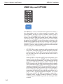
Optional Computer Interface Package
An optional Network Computer Interface Package (Catalog No.
77017 for 100-120Vac; Catalog No. 77018 for 200-240Vac) is
available for use of the QC RUN feature and automatic run data
logging. The requirements for the user-supplied computer are:
A dedicated (one per 16 centrifuges) IBM®-compatible
computer with Pentium® processor running at 75 MHz (or
faster) with an available serial communications port. The
computer must have at least 100MB of free hard drive space,
and be running Microsoft® Windows® V3.1 or 3.11 with at
least 8MB RAM, Windows 95® with at least 16MB RAM, or
Windows NT® V4.0 with at least 16MB RAM. The computer
requires a monitor, keyboard, mouse, and printer with
Windows®-compatible driver.
NOTE A dedicated, directly connected computer is required;
WatchLog Network™ software will not operate correctly
as a network server-based application. Also, running
other software applications, accessories or utilities while
WatchLog Network™ is in use is not advised.
The RC12BP™ Centrifuge is compatible with WatchLog
Network™ systems (revisions below 2.0 require a software
upgrade), but is not compatible with older WatchLog™
software.
1-6
RC12BP™
Installation
Chapter 2: INSTALLATION
This chapter contains instructions to prepare the SORVALL® RC12BP™ centrifuge for operation.
Inspection
1.
When you receive your centrifuge, carefully inspect it for any
signs of shipping damage. If you find damage, report it
immediately to the transportation company and file a damage
claim, then notify Thermo.
2.
Check the parts received against the shipping list; if any parts are
missing, contact Thermo (see back cover).
3.
Remove all packing material, and remove any remaining items
from inside the rotor chamber (where this manual was).
Electrical Requirements
NOTE The centrifuge should be connected to an Overvoltage
Category II circuit, and should have a means of power
interruption at a remote location.
The RC12BP™ has specific power requirements and must be connected to the correct supply for proper performance. The nameplate
on the back panel of the cabinet specify a voltage and frequency
corresponding to one of the following AC supplies:
200 V, 50 Hz, 50 A, single Ø
220 V, 50 Hz, 50 A, single Ø
230 V, 50 Hz, 50 A, single Ø
230 V, 50 Hz, 32 A/P, poly Ø
240 V, 50 Hz, 50 A, single Ø
200 V, 60 Hz, 50 A, single Ø
208 V, 60 Hz, 50 A, single Ø
220 V, 60 Hz, 50 A, single Ø
230 V, 60 Hz, 50 A, single Ø
240 V, 60 Hz, 50 A, single Ø
The supply voltage should be checked with a voltmeter, then you
should verify that the voltage indicated on the nameplate on the back
panel is in agreement with the measured line voltage.
!
CAUTION
The centrifuge can be damaged if it is connected to the wrong
voltage. Check the voltage listed on
the nameplate, and measure the voltage at the power source before plugging in the power cord. Thermo is not
responsible for incorrect installation.
If the measured line voltage is not within 10% of the voltage specified
on the nameplate, do not connect the power cord and operate the
centrifuge or damage to the centrifuge may result. Contact Thermo or
your local representative of SORVALL® products to see if the
centrifuge can be modified for your voltage. The centrifuge system
includes a ground wire with 50 A circuit protector on each positive
power lead.
2-1
SORVALL® Centrifuges
Installation
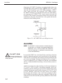
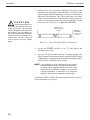
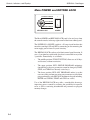
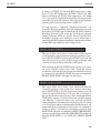
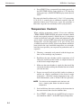
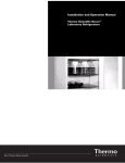
Single phase RC12BP™ Centrifuges are equipped with a three-wire
cord with three-prong connector to fit a NEMA 6-50P (50A, 2-pole
and earth, 1Ø) receptacle, or, on 230V 50Hz centrifuges, a CEE-17
(63A, 2-pole and earth, 1Ø) receptacle. 230V 50Hz polyphase
RC12BP™ Centrifuges are equipped with a four-wire cord with fivepin connector to fit a CEE-17 (32A, 3-pole, neutral and earth, 3Ø)
receptacle. This cord may be changed to meet local electrical code
requirements; the green and yellow wire is the ground and must be
connected to the centrifuge frame.
50 AMP CIRCUIT
PROTECTOR
WALL
OUTLET
MEASURED
LINE
VOLTAGE
50 AMP CIRCUIT
PROTECTOR
Figure 2-1. RC12BP™ Electrical Requirements
Location
NOTE The RC12 BP™ is to be installed in a Pollution Degree 2
environment at an altitude not exceeding 2000 meters
(6560 feet), and is a Class A product not intended for
home use (operation in a domestic environment could
cause radio interference).
!
CAUTION
Locate the centrifuge on a
level floor to avoid rotor imbalance
during operation.
Locate the RC12BP™ on a level floor. For the centrifuge to function
properly, ambient temperature and air circulation are very important.
To ensure free air circulation, the centrifuge must be positioned so that
no air vents are blocked, allowing for its physical size (see figure 22) plus an additional 15 cm (6 inches) on each side, and a minimum
of 5 cm (2 inches) behind the centrifuge (10 cm [4 inches] or more is
desired).
Ambient air temperature at the centrifuge air inlets must be between
5°C to 40°C (41°F to 104°F), with relative humidity ≤90% noncondensing, for the centrifuge to operate. Ideal ambient temperature
to meet all performance specifications is between 20°C to 35°C (68°F
to 95°F), therefore, avoid areas near heat sources (for example,
heating pipes and radiators). Also, avoid close grouping of centrifuges or other heat-producing laboratory equipment. Generally, the
cooler the location, the better the operating conditions will be for the
centrifuge.
2-2
RC12BP™
Installation
Figure 2-2. Centrifuge Dimensions
Installation
A Preinstallation Kit (Catalog No. 22001) is supplied for UL/CE
compliance. Install the Preinstallation Kit according to instructions
supplied with the kit.
To install the RC12BP™:
1.
Position the RC12BP™ in an operating location that satisfies the
criteria specified in the previous Location paragraph. With the
Preinstallation Kit installed, the operating location is so that the
two tabs (under the front edge of the centrifuge) are flush against
and aligned with the preinstalled hold-down brackets.
2.
Secure the centrifuge to the brackets by installing a shackle and
a locking bolt (supplied with the kit) through each tab/hold-down
bracket eyelet and tightening.
2-3
SORVALL® Centrifuges
Installation
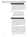
3.
!
CAUTION
The locking stabilizers must
be used as explained to lift the front
caster off the floor. The centrifuge
can be damaged if it is operated when
the stabilizers are not properly adjusted. After adjusting the stabilizers,
make sure that the centrifuge is reasonably level, and that it does not
rock on three of the four support
points.
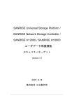
By hand, lower the two locking stabilizers in the front of the
centrifuge until they lightly contact the floor. Use the 9/16-inch
wrench (supplied with the centrifuge) to rotate each stabilizer an
additional two revolutions. This will raise the front caster about
3 mm (1/8 inch) off the floor. Check that the centrifuge does not
rock on its four support points, the two front stabilizers and the
two rear casters (see figure 2-3). Read the CAUTION.
APPROX. 3 mm
(1/8 inch) OFF THE
FLOOR
LOCKING
STABILIZER
(9/16 inch HEX
[≈ 14 mm])
Figure 2-3. Front Locking Stabilizer Adjustment
4.
Be sure the POWER switch is set to "O", then plug in the
centrifuge power cord.
5.
Optional: To be certain the centrifuge is working properly, turn
to the Customer Control Inspection paragraph located in Chapter
5, Maintenance, and perform the procedures listed under Speed
Control, Timer, and Temperature Control.
NOTE If the centrifuge is to be connected with the optional
Network Computer Interface Package for automatic quality control and run logging capability, Thermo or a local
representative for SORVALL® products will install the
package components as described in the WatchLog
Network™ User's Manual (supplied in the package).
After the RC12BP™ satisfies the inspection/performance criteria, it
can be considered ready for use.
2-4
RC12BP™
Controls, Indicators, and Displays
Chapter 3: CONTROLS, DISPLAYS
and INDICATORS
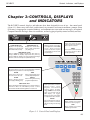
The RC12BP™ controls, displays and indicators have been designed for ease of use – the control panel
(figure 3-1) allows entry with visual verification of set parameters and current conditions, prompts action
if an entry is inappropriate (remains blinking), and communicates status with user messages. An optional
Computer Interface Package allows for automatic, on-line logging of quality control and daily run data.
RUN DISPLAY
SPEED (RPM / RCF)
TEMPERATURE (°C)
Displays the current calcuDisplays rotor speed (rpm)
or RCF, g force, during a run
lated sample temperature
(when RCF indicator is lit).
(°C) during a run.
TIME (MIN:SEC / ACE)
During a TIME run, displays remaining run time (min:sec);
during a HOLD run, displays elapsed run time (min:sec);
during an ACE run, displays current Accumulated Centrifugal
Effect™ coefficient and exponent (ACE indicator lit).
SET DISPLAY
Displays currently selected basic run parameters in the HOME
screen, advanced feature
screens (for selection of options
or programming), and user advisory messages.
OPTION INDICATORS
Lights show advanced feature
selection status. If an indicator is
lit, the option is selected.
MENU
Accesses the advanced feature
screens (for selection of options
and programming).
PRIMARY FUNCTION KEYS
These keys allow access to the corresponding fields of the SET
display for the specification of new run parameters.
ROTOR
(Future use) To allow selection of the rotor to be used.
SPEED
Allows changing desired
speed (rpm) or RCF (g force).
TEMP
Allows changing desired calculated sample temperature.
RECALL
Allows viewing and selecting
programmed parameters.
TIME / HOLD / ACE
Allows changing desired run duration; runs continue until specified min:sec times out, until STOP is pressed, or until a
specified Accumulated Centrifugal Effect™ is achieved.
NUMERIC KEYPAD
Inputs speed, time, and temperature values; selects
programs and advanced
features (options, programming). CLEAR removes an input
value or a message from the
SET display; +/– toggles
between positive and negative
for temperature value selection.
ENTER
Places input values in memory.
Bypasses advanced features
without selecting or deselecting
them.
START
Starts centrifuge run. Indicator
is lit when a run is in progress.
STOP
Stops centrifuge run. Indicator
is lit during deceleration.
Figure 3-1. Control Panel and Displays
3-1
SORVALL® Centrifuges
Controls, Indicators, and Displays
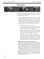
RUN Display
RCF
The RUN display is to the left of the control panel, and is comprised
of three fields of large red LEDs that indicate the current measured/
calculated conditions during a run:
•
The run SPEED (RPM/RCF) field indicates either the current
measured rotor speed (in rpm) or, if RCF is selected (RCF
indicator lit), the relative centrifugal force (or g-force) that is
currently being generated at the maximum radius of the selected
rotor. The rpm values are rounded to 10s above 200 rpm. At run
completion (zero speed, after the door has been unlocked) the
display will show the word "End" until the door is opened.
•
The run TIME (MIN:SEC/ACE) field indicates:
–
If controlled by TIME, the display counts down from set
time, showing the time remaining (in minutes and seconds)
until the run terminates and deceleration begins,
–
If controlled by HOLD (indicated in the control panel SET
display), the display during a run counts up, showing the
time elapsed (expressed in minutes and seconds, up to a
maximum of 300:00) since START was pressed, or
–
If controlled by ACE (Accumulated Centrifugal Effect™,
ACE indicator lit), the RUN display shows the current
calculated ACE value (∫ω2dt). When the set ACE value is
reached, the run terminates and decelerates to a stop. The
displayed value continues to calculate the centrifugal effect
during deceleration to zero to show total accumulation.
Monitoring run duration in alternative terms
During a run, if an alternative run duration key is pressed once (for
example, pressing TIME during an ACE run), the RUN display
will change to show an accumulating value in terms of the newly
selected method. The SET display and ACE indicator will not
change, but will continue to show the control method and value
that was in effect when START was pressed. Run duration will be
controlled by the SET display value, regardless of the alternative
value showing in the RUN display. If that same alternative key is
pressed a second time, the SET display will change to show a
flashing value (from the previous run) expressed in that control
method – entry will change duration control to that method and the
RUN display will continue counting based on the new entry.
Pressing START resets the run.
3-2
RC12BP™
Controls, Indicators, and Displays
Between runs, the RUN display shows the previous run duration
value, viewable in each control mode:
– TIME shows the MIN:SEC value at termination (the SET
display shows the last TIME input value).
– HOLD shows the MIN:SEC value after deceleration to zero.
– After an ACE controlled run, ACE shows the total ACE value
after deceleration to 0 (the SET display shows the termination
value). If the previous run was not controlled by ACE, pressing
ACE shows the ACE value at termination (the SET display
shows the last ACE input value).
•
The run TEMPERATURE (°C) field indicates the current
calculated sample temperature in degrees Celsius, based on rotor
selected, rotor speed, run time, set temperature, and measured
temperature (the calculation assumes that the sample temperature,
rotor temperature, and SET temperature are all equal at the start
of the run).
SET Display
ROTOR
H12000
SPEED
4700
TIMED
04:00
DEG C
22
PROG #
1
The SET display is a 2-line LCD array located at the top of the
control panel. The SET display is used to input and display basic
run parameters, to select options or other advanced features, and
to display advisory messages. The display's contents are referred
to in this manual as a screen; for example, the HOME screen
(described below) displays basic run parameters that correspond
to the (Primary Function) keys below the display.
•
The HOME screen (pictured above) displays currently selected
values for the basic run parameters: ROTOR, SPEED/RCF,
TIMED/HOLD/ACE, DEG C and, if displaying a recalled
program, PROG #. The HOME screen appears in the SET display
after the centrifuge power has been set ON and the diagnostic test
has been completed. In addition, if MENU is pressed to access
the options screens, pressing MENU again will return the HOME
screen to the display.
The SET display is the primary interactive screen on the control
panel, and has a role in all aspects of centrifuge use. Following is
a detailed description of all HOME Screen fields as they relate to
the Primary Function Key functionality, followed by option
selection screens and advanced feature functionality. At the end of
this chapter is a listing of the SET Display advisory messages,
what they mean, and recommended action.
3-3
SORVALL® Centrifuges
Controls, Indicators, and Displays
Main POWER and KEYPAD LOCK
RUN SINGLE PROGRAM
I
ON
FULL FUNCTION
I
O
OFF
RUN ANY PROGRAM
O
KEYPAD LOCK
POWER
The Main POWER and KEYPAD LOCK panel is located away from
the control console, in the top-right corner of the front cabinet panel.
The POWER I/O (ON/OFF) switch is a 50-amp circuit breaker that
turns the centrifuge ON and OFF by connecting or disconnecting the
main supply power from all system circuitry.
The KEYPAD LOCK can be used to limit control panel function. It
uses a 3-position keyswitch with a key that is removable in any of the
3 positions. Functionality is as follows:
•
The middle position, FULL FUNCTION, allows use of all keys
and features, without restriction;
•
The upper position, RUN SINGLE PROGRAM, minimizes
functionality so that set parameters cannot be changed (START,
STOP, and CLEAR are the only active keys);
•
The lower position, RUN ANY PROGRAM, makes it so that
users may only perform runs using run parameters recalled from
program memory (only RECALL, the numeric keypad including
ENTER and CLEAR, START and STOP are active).
Use of the KEYPAD LOCK may offer a considerable advantage,
improving process control by reducing the possibility for operator
error, as well as restricting unauthorized run parameter or program
memory changes.
3-4
RC12BP™
Controls, Indicators, and Displays
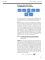
Primary Function Keys
and HOME Screen Fields
ROTOR
TIME
SPEED
HOLD
TEMP
RECALL
ACE
The Primary Function Keys are the keys below the SET display. Each
key is positioned below a corresponding field in the HOME screen,
allowing simple, direct access to basic run parameter controls:
ROTOR (reserved for future use) would be pressed to specify a
different rotor than the one shown in the SET display, which would
be necessary if the rotor or bucket/carrier system installed in the
centrifuge were to change. Because there is only one rotor that is
compatible with the centrifuge at this time, the ROTOR key presently
has no function. As future rotors are added, they will be listed by rotor
name, and the ROTOR key would be pressed to scroll through the
compatible rotors for selection. Correct identification of an installed
rotor is required to establish set SPEED limits, correctly calculate
RCF, and accurately control sample temperature. If a rotor is able to
use buckets/carriers with different maximum radii, each configuration will be listed for selection, to calculate the different RCF. The
ROTOR key is not active when a run is in progress.
NOTE In the future (only after new rotors have been added),
ensure that the installed rotor is correctly identified by
changing the SET rotor name immediately after changing
the installed rotor.
SPEED is pressed to specify a different rotor speed in revolutions per
minute (rpm) or relative centrifugal force (RCF, also known as gforce) than the value shown in the SET display. Speed is selectable
from 150 to 4700 rpm (the maximum rated speed for the H-12000
rotor), or as an equivalent RCF calculated at the maximum radius of
the rotor (rotor geometry only). Changing from rpm to RCF or RCF
to rpm is done by repeatedly pressing SPEED: pressing once causes
the value to flash so a change can be made in the existing mode,
pressing again changes to the other mode and displays a value
equivalent to the previous, pressing again causes that value to flash so
a change can be made, and so on. An entered value will continue to
flash (prompting input) when it is out of range for the rotor. The
formula used to calculate RCF is:
2
RCF = 11.17 x radius in cm x
( )
rpm
1000
3-5
SORVALL® Centrifuges
Controls, Indicators, and Displays
NOTE When changing mode, rpm/RCF values may appear a
digit or two off from the original set value. The centrifuge
translates set RCF values to rpm whole numbers for
speed control purposes, then calculates that rpm whole
number to the closest RCF value. There is no cause for
concern; speed control accuracy is not compromised,
and the slight value difference will not affect the run.
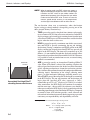
The run duration (from start to termination, when deceleration
begins) setting or control method is changed by pressing one of the
three grouped Primary Function keys:
SPEED
TERMINATION
SET POINT
123456789012345678901234567890121234567890123
123456789012345678901234567890121234567890123
123456789012345678901234567890121234567890123
RUN
123456789012345678901234567890121234567890123
123456789012345678901234567890121234567890123
123456789012345678901234567890121234567890123
TOTAL
123456789012345678901234567890121234567890123
123456789012345678901234567890121234567890123
123456789012345678901234567890121234567890123
123456789012345678901234567890121234567890123
123456789012345678901234567890121234567890123
123456789012345678901234567890121234567890123
123456789012345678901234567890121234567890123
123456789012345678901234567890121234567890123
123456789012345678901234567890121234567890123
123456789012345678901234567890121234567890123
123456789012345678901234567890121234567890123
123456789012345678901234567890121234567890123
123456789012345678901234567890121234567890123
123456789012345678901234567890121234567890123
123456789012345678901234567890121234567890123
123456789012345678901234567890121234567890123
TIME
Accumulated Centrifugal Effect™
calculating the area under the curve
•
TIME is pressed to specify a length of time (minutes and seconds,
to a maximum of 99:99) from run start to termination. In the RUN
display, minutes and seconds begin counting down from the input
value when START is pressed. The run terminates and deceleration
begins when the timer reaches zero.
•
HOLD is pressed to specify a continuous run which, once started,
runs until STOP is pressed (terminating the run and initiating
deceleration). During a continuous run, HOLD will be in the SET
display, and the time elapsed from when START was pressed will
appear in the RUN display. The timer will accumulate up to 300
minutes – if a run continues beyond that, displayed run time will no
longer reflect elapsed time, but will remain fixed at 300:00. Whenever
it is possible for such an extended run to occur, an external timing
method is recommended.
•
ACE is pressed to specify an Accumulated Centrifugal Effect™
value. When ACE control is selected, the centrifuge calculates the
effect of speed in relation to time (the shaded area in the illustration
at left), adjusting run duration to account for acceleration variation.
This variation can be attributed to rotor load/configuration differences
(affecting inertia), fluctuations in line voltage (affecting motor
power), or slight mechanical differences including normal wear.
When START is pressed, the realizedACE value begins to accumulate
in the RUN display. The run will terminate and deceleration will
begin when the specified ACE value (expressed as ∫ω2dt*,
controllable up to 9.99 x 1030 [displayed as 9.99e30]) is reached.
After termination, the RUN display will continue to accumulate
until the rotor stops – this run total is for reference; care should be
taken not to confuse the RUN display's final accumulation with the
controlling input/timeout value, found in the SET display. Compared
to control by time, ACE selection provides a more advanced and
relevant form of run duration control, thereby improving separation
consistency, run reproducibility, and dependability of results.
* The integral value can be calculated deriving the following formula:
∫w2dt = w2∫dt = ω2∆t
Where:
∆t = Change in time (seconds)
and ω2 = Angular speed
= 2π [n/60]
n = Speed (rpm)
3-6
RC12BP™
Controls, Indicators, and Displays
During a run, to view in an alternative duration control mode (for
example, to monitor accumulating TIME when an ACE run is in
progress), press one of the other two duration control keys once – this
changes the RUN display to show an accumulating value in that alternative
mode without altering the way duration is controlled. In this viewing
condition, the SET display field header does not change, nor will the
status of the ACE indicator (both continuing to indicate the set control
mode), but the SET value will change to show the last value entered in the
alternative mode. If you press the same key a second time, the run will then
change to that control method, using the value that was in the SET display
as the controlling value until a different one is entered. Pressing START
resets the run.
NOTE If you change the duration control mode to TIME during a
run, time will begin to count down from the set value the
moment the change is made (unless the run was previously controlled by time and you are returning, in which
case the run resumes counting from the value that was
remaining when TIME was exited). If you change to ACE
control, the last-set ACE value that is displayed the moment the change is made will control termination, so that if
you change to ACE when the run has already exceeded
the value, the run will terminate immediately.
Between runs, the RUN display shows the previous run duration
values, viewable in each control mode. Pressing TIME shows the
MIN:SEC value at termination (the SET display shows the last TIME
input value). HOLD shows the total MIN:SEC value after deceleration
to zero. After an ACE controlled run, ACE shows the total ACE value
after deceleration to zero (the termination value is in the SET display).
If the previous run was not controlled by ACE, pressing ACE shows
the ACE value at termination (the SET display shows the last ACE
input value). Always be sure of the control method and value before
pressing START.
TEMP is pressed to change desired calculated sample temperature
(°C, settable from –10 to 40) that is controlled by the centrifuge during
a run. The centrifuge automatically considers the rotor selected, rotor
speed, run time, set temperature, and measured temperature to
calculate and maintain sample temperature during the run. The
calculation assumes that the sample temperature, rotor temperature,
and SET temperature are all equal at the start of the run (as they must
be any time that temperature control is critical).
RECALL is pressed to access program memory. Saved parameters
are recalled by inputting a specific program number. By pressing
START, you begin a run using the run parameters displayed. Also,
programs can easily be recalled and modified to create new run
parameters without fear of damaging the original program, because
information that is saved in memory cannot be overwritten by using
the RECALL key (modifying or replacing a program is reserved for
the SELECT SAVE RUN option under the MENU key).
3-7
SORVALL® Centrifuges
Controls, Indicators, and Displays
MENU Key and OPTIONS
The MENU key accesses advanced feature options listed above it,
plus other features such as saving parameters to memory. After
pressing MENU, pressing 1 accesses a secondary screen to view or
enter values, plus confirm option selection; pressing 0 deselects
options; pressing ENTER steps through options without changing
selections or settings, and on secondary screens, enters values to select
the option. Pressing MENU again exits the options and returns to the
HOME screen without entering/selecting a flashing value. Automatic
logging of QC RUN and daily run data is possible using WatchLog
Network™ software (packaged with the optional network computer
interface package) on a dedicated computer.
•
QC RUN allows simple, automatic quality control run speed/
temperature verification when used with the optional computer
interface package. The QC RUN feature will run and document
the data from each set of parameters that has been saved in
program memory.
When QC RUN is selected, the SET screen will prompt you to
prepare for the run and press START to begin – the centrifuge
will start running program number 1, and systematically run each
program in-order through program number 9. While the QC
RUN is in progress, the parameters of the program that is running
will be in the SET display. At the end of each program, the data
from that segment of the QC RUN sequence will be written to the
QC RUN log. If STOP is pressed while a QC RUN is in progress,
the data collected up through the last program completed before
termination will be logged (data from the program that was in
progress will be logged and labelled incomplete). If a system
fault occurs while a QC RUN is in progress (other than a
computer failure, disabling WatchLog Network™), the data
would be logged as if STOP was pressed, and a fault type will be
recorded.
3-8
RC12BP™
Controls, Indicators, and Displays
If, during the QC RUN, an observed RUN display temperature is
not within ±2°C of SET temperature (as could be the case when
there is a significant temperature change with a short run), the
centrifuge will continue to repeat that step of the QC RUN
sequence until the observed temperature is within range. The
data will not be logged until the programmed run is completed
successfully, at which time the centrifuge will move on to the
next set of programmed parameters.
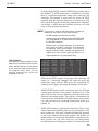
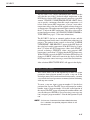
NOTE If you plan on using the QC RUN feature, consider the
following as you save runs to program memory:
• QC RUN programs should not use HOLD.
• Programs with factory default settings of SPEED=400
rpm, TIME=00:00, and TEMP=40 will be ignored in
the QC RUN sequence.
• Although you may choose otherwise, to minimize the
time it takes to perform a QC RUN, we recommend
the following: Starting with program 1, save runs to
program memory in order – sorted first by temperature
(highest first), then, if there is more than one run at a
single temperature, by speed (lowest first).
ROTOR SPEED
H12000 2900
H12000 4000
H12000 3800
H12000 4700
H12000
400
FOR EXAMPLE :
The programs at right are listed in correct
order for using QC RUN; PROG # 5 (with
factory default settings) will be ignored
by the centrifuge when performing the
run (program values shown are for
example purposes only, actual set
parameters will vary).
TIMED
04:00
03:00
03:45
05:30
00:00
DEG C PROG #
22
1
22
2
4
3
4
4
40
5
While the QC RUN sequence is in progress, the centrifuge will
output (to a connected computer) the observed speed and
temperature along with the SET speed and temperature for
automatic data logging and simple performance verification.
•
SLOW START chooses gentle acceleration from 0 to 250 rpm
(acceleration transitions to the normal, maximum rate at 250
rpm), with the slow start rate defined by selection of one of ten
different acceleration profiles. The profiles are numbered for
ease of selection, with number 1 being the slowest, most gradual
rate, and each successive rate being incrementally faster up to
number 10.
•
SLOW STOP chooses gentle deceleration from 500 to 0 rpm
(normal deceleration braking from set speed transitions to the
more gradual rate at 500 rpm), with the rate defined by selection
of one of ten different deceleration profiles. The profiles are
numbered for ease of selection, with number 1 being the slowest,
most gradual rate, and each successive rate incorporating
incrementally more braking up to number 10. Particularly when
3-9
SORVALL® Centrifuges
Controls, Indicators, and Displays
establishing blood bank protocols, for optimized braking with minimal
resuspension, we recommend starting at setting 5 and adjusting
up or down as needed. Selection of BRAKE OFF will have an
affect on SLOW STOP (see the NOTE under BRAKE OFF).
•
BRAKE OFF deactivates normal deceleration braking for a
coasting stop from any specified speed (in rpm) between 4700
and 0. BRAKE OFF transition speed is set independently of set
run speed, and is not affected by changes to set run speed. If the
transition speed is set higher than the set run speed, at run
termination, the centrifuge will coast to a stop from set speed.
NOTE If SLOW STOP and BRAKE OFF are both selected:
– If the BRAKE OFF transition speed is set to 500 rpm
or higher, the SLOW STOP selection will be ignored.
– If the BRAKE OFF transition speed is set below 500
rpm, the centrifuge will decelerate with full braking to
500, transition to the specified SLOW STOP rate,
then change to a coasting stop when the specified
BRAKE OFF transition speed is reached.
•
EXAMPLE:
If you have a set temperature of 22
and set the maximum temperature to
24, an overtemperature alert will occur
if the calculated sample temperature
reaches 25. If the set temperature is
then changed to 4, the maximum
temperature setting will automatically
change to 6, based on the previously
calculated offset value.
CHANGE OVERTEMPERATURE LIMIT allows changing the
maximum allowable sample temperature to establish a new
overtemperature offset value. The centrifuge calculates the
difference between the set and the maximum temperatures, and
retains that value as an offset to apply to future runs, until it is
changed. The retained offset will apply to any normal (manualentry) runs as well as to any recalled program runs (specific
overtemperature limit settings cannot be saved in run programs).
See the EXAMPLE at left.
During a run, if the calculated sample temperature in the RUN
display goes above the maximum allowable sample temperature,
a SAMPLE TEMPERATURE OVER LIMIT message will appear
in the SET display, and an alarm will sound. This may indicate
a condition requiring simple corrective action, or it could indicate
a refrigeration problem (see "SAMPLE TEMPERATURE OVER
LIMIT" on page 3-16).
This overtemperature alert is not activated and a precool mode
begins if the RUN display temperature is more than 2°C over the
SET value when START is pressed, or when a temperature change
between programs occurs in a STEP RUN. In each case, a SAMPLE
OVERTEMP – PRE-COOLING message will appear and an alarm
will sound. Pressing CLEAR removes the message and shuts off the
alarm, allowing the run to continue as a precool run (P-COOL
replaces DEG C as the field header in the SET display during precool
mode). A precool mode is automatic during a QC RUN; the message
and alarm are disabled, and the program is repeated until temperature
is within 2° of set.
3-10
RC12BP™
Controls, Indicators, and Displays
•
EXAMPLE:
If you have a set temperature of 22
and set the minimum temperature to
20, an undertemperature alert will
occur if the calculated sample
temperature goes down to 19. If the
set temperature is then changed to 4,
the minimum temperature setting will
automatically change to 2, based on
the previously established offset value.
CHANGE UNDERTEMPERATURE LIMIT allows changing
the minimum allowable sample temperature to establish a new
undertemperature offset value. The centrifuge calculates the
difference between the set and the minimum temperatures, and
retains that value as an offset to apply to future runs, until it is
changed. The retained offset will apply to any normal (manualentry) runs as well as to any recalled program runs (specific
undertemperature limit settings cannot be saved in run programs).
See the EXAMPLE at left.
During a run, if the calculated sample temperature in the RUN
display goes below the minimum allowable sample temperature,
a SAMPLE TEMPERATURE UNDER LIMIT message will
appear in the SET display, and an alarm will sound. This may
indicate a condition requiring simple corrective action, or it
could indicate a refrigeration problem (see "SAMPLE
TEMPERATURE UNDER LIMIT" on page 3-16).
This undertemperature alert is not activated and a preheat mode
begins if the RUN display temperature is more than 2°C under the
SET value when START is pressed, or when a temperature change
between programs occurs in a STEP RUN. In each case, a SAMPLE
UNDERTEMP – PRE-HEATING message will appear and an
alarm will sound. Pressing CLEAR removes the message and shuts
off the alarm, allowing the run to continue as a preheat run (P-HEAT
replaces DEG C as the field header in the SET display during preheat
mode). A preheat mode is automatic during a QC RUN; the message
and alarm are disabled, and the program is repeated until temperature
is within 2° of set.
•
STEP RUN allows the linking-together of up to three sets of
programmed run parameters to automatically perform step run
protocols. When step run is selected, the specified programs must
specify the same rotor at similar temperatures. Step runs can be
saved to program memory (program numbers 10-15) for simple
recall in future use (see SAVE RUN below).
•
SAVE RUN allows pre-programming of up to 15 different sets of
run parameters (9 standard runs, and 6 step runs) for simple recall
and error-free run reproducibility. In addition to basic parameters,
all option selections and settings (excluding rotor name,
overtemperature limit, and undertemperature limit) will also be
saved to program memory. To eliminate inadvertent loss of
existing programs, the save run sequence alerts users before
overwriting. The convenient RECALL key allows browsing
through existing programs for selection or reference.
NOTE If you plan to use the QC RUN feature, specific guidelines
should be considered when saving parameters to memory
(see QC RUN on page 3-8).
3-11
SORVALL® Centrifuges
Controls, Indicators, and Displays
Numeric Keypad
The Numeric Keypad is used to input speed, time, and temperature
values into the HOME screen and to select the advanced features. The
ENTER key enters newly inputted speed, time, temperature, and RCF
values into memory; it also allows you to bypass options in the
OPTIONS sequence without selecting or deselecting them. The
CLEAR key sets a blinking value to zero in the SET display, clears
entry errors or fault messages, and if the barcoding accessory is used
and the door is open, deletes barcode data input after the last run was
completed (keypad lock must be set to FULL FUNCTION). The +/–
key is used to toggle between positive (+) and negative (–) temperature
values.
3-12
RC12BP™
Controls, Indicators, and Displays
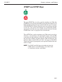
START and STOP Keys
The green START key is used to start the centrifuge run. When the
START key is pressed, the green LED status indicator on the key will
blink until the rotor begins to spin (which could take up to 20 seconds
if SLOW START is selected). Once the rotor starts spinning, the light
on the key will remain ON through run termination (during
deceleration) until the rotor stops spinning and door unlocks. Pressing
START when a run is in progress resets run duration.
The red STOP key is used to terminate a run. When stop is pressed (or
whenever a run terminates and deceleration begins), the red LED
status indicator light on the key will be ON, and will remain ON until
the rotor stops spinning and door unlocks. When that happens, the
indicator light is turned OFF, and "End" will appear in the RUN
Temperature display to prompt the user to open the chamber door and
remove sample.
NOTE The START and STOP keys are usable only when the
HOME screen is in the SET display. If any other screen
is in the display, the keys are disabled.
3-13
SORVALL® Centrifuges
Controls, Indicators, and Displays
SET Display Advisory Messages
When the RC12BP™ detects a system fault or a situation requiring
operator action, an advisory message appears in the SET display and an
alarm will sound to alert the operator. In most cases, pressing CLEAR
shuts off the alarm and removes the message from the display (if not, in
almost all other cases, turning the main POWER switch OFF and back
ON will do so). The messages can be divided into two types, Problem
Conditions and Terminal Conditions. Possible messages are listed here by
message type, sorted alphabetically, with a description of the condition
and the appropriate action.
Problem Conditions
Problem Condition messages alert the user to a situation that will
not terminate a run in progress (except for ROTOR IMBALANCE, NO ROTOR, or POWER FAILURE), but may prevent a
run from starting. In many cases, a Problem Condition will force
action to be taken, but can be remedied by the user.
DOOR MUST BE OPENED BETWEEN RUNS
START was pressed, but the chamber door had not been
opened since the previous run ("End" will remain in the RUN
Temperature display until the door has been opened). The
centrifuge will not start. Open the door (if you had not
accessed the chamber since the last run, remove previous
sample and reload the rotor), then close the door and press
START. If the message reappears when START is pressed, it
indicates a door switch failure – remove all sample from the
rotor, unplug the centrifuge and contact Thermo Service.
DOOR OPEN – RUN NOT STARTED
START was pressed, but the centrifuge did not detect that the
chamber door was closed. The centrifuge will not start. Close
the chamber door and press START. If the message then appears
when the door is closed, it indicates a door switch failure. In that
case, remove all sample from the rotor, then unplug the centrifuge and contact Thermo Service.
MEMORY FAILURE – CONTACT SERVICE
A memory problem was discovered during the centrifuge
startup routine. All run information that had been saved to
program memory has been lost and overwritten with
SPEED=400 rpm, TIME=00:00, DEG C=40, Options OFF.
3-14
RC12BP™
Controls, Indicators, and Displays
A MEMORY FAILURE fault could indicate a processing
problem, but typically means that the battery has gone dead.
Press CLEAR, turn the main power switch OFF and back
ON to see if the fault recurs, then contact Thermo Service.
Until the condition is repaired, the centrifuge will not communicate to WatchLog Network™ (logging run data will not
occur), but the centrifuge should still be operational. If
programmed operation is desired, resave the run parameters,
but leave the main power switch ON until the condition is
repaired, so that saved programs are not lost.
NO ROTOR DETECTED
When START was pressed, a rapid increase in rpm was
detected (that could occur if no rotor was installed), and the
run was terminated immediately. After the door unlocks,
install a rotor and restart the run. (In future use, if rotors are
added: If a rotor was installed, check to be sure that it was
correctly identified in the SET display. If not, either change
the rotor or change the setting so that they match, then restart
the run.) If a correctly identified rotor was installed, it
indicates either that the drive shaft is damaged or that a
tachometer problem exists. Remove all sample from the
rotor, unplug the centrifuge and contact Thermo Service.
(WatchLog Network™ record: NO ROTOR.)
POWER FAILURE – RUN RESTARTED
A momentary power failure occurred during the run, and the
rotor speed was still within 200 rpm of SET speed when the
power was restored. The automatic restart feature resumed
the run in progress. (WatchLog Network™ does not document this occurrence.)
POWER FAILURE – RUN TERMINATED
A power failure occurred during the run, and the rotor
speed was not within 200 rpm of SET speed when power
was restored, disabling automatic restart. The run in
progress was terminated. (If power is restored before zero
speed, WatchLog Network™ record: POWER FAIL. If
power is restored after zero speed, there will be no record
of the run.)
ROTOR IMBALANCE – BALANCE ROTOR
Excessive rotor vibration was detected; the run in progress
was terminated. Rebalance the rotor according to directions
in the rotor instruction manual, then restart the run. WatchLog
Network™ record: IMBALANCE.)
3-15
Controls, Indicators, and Displays
SORVALL® Centrifuges
SAMPLE OVERTEMP – PRE-COOLING
The RUN display temperature was more than 2°C above the
SET temperature either when START was pressed, or during
a STEP RUN at a moment when the programmed SET
temperature changed. Press CLEAR to continue the run as a
Precool run, or press STOP to terminate the run to remove
sample before precooling the chamber to SET temperature.
During a Precool run, P-COOL replaces the DEG C field
header in the SET display until RUN temperature is within
2°C of SET value.
SAMPLE TEMPERATURE OVER LIMIT
During a run, when the pre-cool feature was not active (see
SAMPLE OVERTEMP – PRE-COOLING, above), the RUN
display temperature went above the maximum allowable
(overtemperature limit) setting. Check all possible causes:
a. SET temperature too low for rotor/speed combination,
b. overtemperature limit too close to the SET temperature (see
page 3-10, CH
c. ambient air temperature at the centrifuge inlet > 35°C,
d. centrifuge air inlet blocked or proper clearance not observed
(see page 2-2, Location).
Check all possible causes before contacting Thermo Service. (WatchLog
Network™ record: OVERTEMP.)
SAMPLE TEMPERATURE UNDER LIMIT
During a run, when the preheat feature was not active (see
SAMPLE UNDERTEMP – PRE-HEATING below), the RUN
display temperature went below the minimum allowable
(undertemperature limit) setting. The limit setting may be
too close to the SET temperature (see page 3-11, CHANGE
UNDERTEMPERATURE LIMIT) – try setting a lower
undertemperature limit. If the problem persists, there may be
a refrigeration system problem. Contact Thermo Service.
(WatchLog Network™ record: TEMP. UNDER LIMIT.)
SAMPLE UNDERTEMP – PRE-HEATING
The RUN display temperature was more than 2°C below the
SET temperature either when START was pressed, or during
a STEP RUN at a moment when the programmed SET
temperature changed. Press CLEAR to continue the run as a
Preheat run, or press STOP to terminate the run to remove
sample before preheating the chamber to SET temperature.
During a Preheat run, P-HEAT replaces the DEG C field
header in the SET display until RUN temperature is within
2°C of SET value.
3-16
RC12BP™
Controls, Indicators, and Displays
THE SET SPEED EXCEEDS ROTOR MAX
- ENTER A LOWER SET SPEED
(Future use, if rotors are added.) START was pressed, but the
centrifuge detected a set SPEED value that was too high for
the SET rotor. The centrifuge will not start. This can occur if
you change the SET rotor, but the SET speed is too high for
the newly specified rotor, or if you recall a program that was
saved based on the use of a different, higher-speed rotor.
Make sure the SET rotor specified is the installed rotor, then
enter an rpm or RCF value that does not exceed the maximum allowable for the rotor, or install and specify a different
rotor, and press START.
THE SET SPEED EXCEEDS ROTOR MAX
- RUN TERMINATED
(Future use, if rotors are added.) This can occur when a QC
RUN or STEP RUN is in progress, and a program is encountered that has a higher set speed than the maximum speed of
the SET rotor (indicating that the program was saved based
on the use of a different, higher-speed rotor). The SET rotor
cannot be used with the programs as saved. Make sure the
SET rotor is installed, change to an acceptable rotor or
review and change the programs saved before reattempting.
(WatchLog Network™ record: SET SPEED.)
THE SET TIME = 0:00 - ENTER A VALID TIME
START was pressed with a set run duration value of zero.
The centrifuge will not start. Press one of the three run
duration control keys (TIME/HOLD/ACE), input a value,
then press START.
3-17
SORVALL® Centrifuges
Controls, Indicators, and Displays
Terminal Conditions
Terminal Condition messages alert the user to a serious fault condition. Runs are disallowed or terminated. These conditions typically
cannot be remedied by the user; the centrifuge should be removed
from service until it is repaired by Thermo Service.
Alternate Tach Failure
!
WARNING
Do not open the chamber
door when the rotor is spinning.
In the event of a tachometer failure
(or any failure where RUN speed does
not register), the brake will not operate
and the rotor will coast to a stop –
from high speed, deceleration to 0
could take as long as 30 minutes.
Before using the mechanical override
to open the chamber door, use the
viewing port in the door to make sure
that the rotor has stopped spinning.
Opening a chamber door when a rotor
is spinning exposes hazardous
energy; contact with a spinning rotor
could cause personal injury.
During a run, the primary tachometer signal was indicating
2000 rpm or more while the secondary tachometer signal
was indicating 0 rpm. Wait for the rotor to stop spinning (this
could take as long as 30 minutes), then use the mechanical
override to remove all sample from the rotor, unplug the
centrifuge and contact Thermo Service. Read the WARNING. (WatchLog Network™ record: TACH FAULT.)
AIR TEMP SENSOR FAILURE
The chamber air temperature sensor indicated either an open
circuit, or a temperature above 45°C. The fault indicates a
sensor failure or a refrigeration system problem. After the
rotor stops and the chamber door is opened, note if the
chamber is warm – if so, the rotor may be too hot to touch.
Unplug the centrifuge and contact Thermo Service. (WatchLog
Network™ record: AIR SENSOR.)
COMPRESSOR FAILURE
While the refrigeration compressor was working to cool, the
chamber air temperature sensor detected an increase of 10°C
or more from when the compressor first turned on. The fault
indicates a refrigeration system problem. After the rotor
stops and the chamber door is opened, note if the chamber is
warm – if so, the rotor may be too hot to touch. Unplug the
centrifuge and contact Thermo Service. (WatchLog Network™ record: COMPRESSOR.)
COMPRESSOR SOLENOID FAILURE
While the refrigeration compressor was working to heat, the
chamber air temperature sensor detected a decrease of 10°C
or more from when the compressor first turned on. The fault
indicates a refrigeration solenoid/valve problem. Unplug the
centrifuge and contact Thermo Service. (WatchLog Network™ record: COMP. SOLENOID.)
3-18
RC12BP™
Controls, Indicators, and Displays
CONDENSER PRESSURE TOO HIGH
The refrigeration system's high side pressure sensor indicated either an open circuit, or an internal pressure above
450 psi. The fault typically indicates a refrigeration system
problem. Possible causes include:
•
user repairable items such as ambient air temperature too
high, centrifuge air inlet blocked or proper clearance not
observed (see page 2-2, Location);
•
Thermo Service repairable items such as a blocked condenser, condenser fan failure, system overcharge, or pressure sensor malfunction.
Check user repairable causes before unplugging the centrifuge and contacting Thermo Service. (WatchLog Network™
record: COMPRESSOR.)
DOOR CLOSED SWITCH FAILURE
A run was in progress when the door closed switch opened,
indicating a circuit failure. Remove all sample from the rotor
after it stops, then unplug the centrifuge and contact Thermo
Service. (WatchLog Network™ record: DOOR.)
DOOR LOCK SWITCH FAILURE
A run was in progress when the door lock switch opened,
indicating a circuit failure. Remove all sample from the rotor
after it stops, then unplug the centrifuge and contact Thermo
Service. (WatchLog Network™ record: DOOR.)
DOOR LOCK SWITCH SHORTED
At run completion, the door lock switch did not open, indicating a circuit failure. The interlock motor is de-energized;
another run will not start. Remove all sample from the rotor,
then unplug the centrifuge and contact Thermo Service.
DOOR NOT LOCKED – CONTACT SERVICE
After START was pressed, the door lock switch did not close,
indicating a circuit failure. The run will not start and the interlock motor is de-energized. Remove all sample from the rotor,
unplug the centrifuge and contact Thermo Service.
DRIVE BOX FAULT
The microcomputer detected that the drive box was not
responding, possibly indicating an error internal to the drive
box electronics, or a brake resistor overheat condition. Wait
for the rotor to stop spinning (this could take as long as 30
minutes), then use the mechanical override to remove all
sample from the rotor, unplug the centrifuge and contact
Thermo Service. Read the WARNING on page 3-18.
(WatchLog Network™ record: DRIVE.)
3-19
Controls, Indicators, and Displays
SORVALL® Centrifuges
DRIVE FAULT AT START-UP
After START was pressed, the microcomputer detected that
the tachometer was not responding as power was applied to
the drive motor, without any indication of a drive fault. May
indicate a motor problem or, if it occurs at same time as Tach
Fault, a tachometer problem. Wait for the rotor to stop
spinning (this could take a few minutes), then use the mechanical override to remove all sample from the rotor, unplug the centrifuge and contact Thermo Service. Read the
WARNING on page 3-18. (WatchLog Network™ record:
DRIVE.)
DRIVE FAULT DETECTED – CALL SERVICE
The microcomputer detected either that the drive motor was
not responding, or that the tachometer circuit failed. Wait for
the rotor to stop spinning (this could take as long as 30
minutes), then use the mechanical override to remove all
sample from the rotor, unplug the centrifuge and contact
Thermo Service. Read the WARNING on page 3-18.
(WatchLog Network™ record: DRIVE.)
DRIVE FAULT DURING BRAKING
After run termination while the rotor is decelerating and the
drive was working to reverse, either the drive box stopped
responding or a speed increase was detected. Wait for the
rotor to stop spinning (this could take as long as 30 minutes),
then use the mechanical override to remove all sample from
the rotor, unplug the centrifuge and contact Thermo Service.
Read the WARNING on page 3-18. (WatchLog Network™
record: DRIVE.)
FLOOR TEMP SENSOR FAILURE
The chamber floor temperature sensor has indicated either a
temperature above 55°C, or an open circuit. The fault indicates a sensor failure or a refrigeration problem. After the
rotor stops and the chamber door is opened, note if the
chamber is warm – if so, the rotor may be too hot to touch.
Unplug the centrifuge and contact Thermo Service. (WatchLog
Network™ record: FLOOR SENSOR.)
MOTOR CURRENT FEEDBACK FAULT
The microprocessor has detected that the feedback current
returning from the drive motor was improbable based on the
current sent to the motor. The fault indicates a motor/drive
box, power supply, or tachometer problem. Wait for the rotor
to stop spinning (this could take as long as 30 minutes), then
use the mechanical override to remove all sample from the
rotor, unplug the centrifuge and contact Thermo Service.
Read the WARNING on page 3-18. (WatchLog Network™
record: DRIVE.)
3-20
RC12BP™
Controls, Indicators, and Displays
MOTOR OVERHEAT DETECTED - CALL SERVICE
Indicates that high motor temperature has tripped its thermal
switch, or that the motor temp circuit is otherwise open. Wait
for the rotor to stop spinning, remove all sample from the
rotor, unplug the centrifuge and contact Thermo Service.
(WatchLog Network™ record: MOTOR SENSOR.)
ROTOR OVER MAX SPEED – CONTACT SERVICE
Speed was more than 200 rpm higher than the rotor's
maximum rated speed, indicating improper speed control
or a faulty tachometer circuit. Wait for the rotor to stop
spinning (this could take as long as 30 minutes), then use
the mechanical override to remove all sample from the
rotor, unplug the centrifuge and contact Thermo Service.
Read the WARNING on page 3-18. (WatchLog Network™
record: ROTOR OVERSPEED.)
SHUNT OVERHEAT DETECTED - CALL SERVICE
Indicates that high brake resistor temperature has tripped its
thermal switch (indicating that the resistor was energized
when it should not have been), or that the brake circuit is
otherwise open. Wait for the rotor to stop spinning, remove
sample from the rotor, unplug the centrifuge and contact
Thermo Service. (WatchLog Network™ record: SHUNT
OVERDRIVE.)
TACH FAULT DETECTED – CALL SERVICE
During a run, the tachometer signal was lost, indicating
that the tachometer circuit has failed, or that the drive
shaft is damaged. Wait for the rotor to stop spinning (this
could take as long as 30 minutes), then use the mechanical
override to remove all sample from the rotor, unplug the
centrifuge and contact Thermo Service. Read the WARNING on page 3-18. (WatchLog Network™ record: TACH
FAULT.)
UNEXPECTED ISR – CALL SERVICE
The microprocessor has detected erroneous information or
encountered a processing problem. The run in progress may
or may not be terminated; the controls and displays might
lock-up. Turn the main power switch OFF and back ON. If
the fault recurs, turn the main power switch OFF. Wait for
the rotor to stop spinning (this could take as long as 30
minutes), then use the mechanical override to remove sample
from the rotor, unplug the centrifuge and contact Thermo
Service. Read the WARNING on page 3-18. (WatchLog
Network™ may not record: UNEXPECTED ISR.)
3-21/3-22
Controls, Indicators, and Displays
SORVALL® Centrifuges
RC12BP™
Operation
Chapter 4: OPERATION
This chapter provides the operating procedures for the RC12BP™ Centrifuge.
NOTE Before turning on the RC12 BP™ for the first time, be sure it is properly installed (see Chapter 2,
Installation). Before using the RC12 BP™ for the first time, we recommend that you read all
WARNINGS and CAUTIONS, as well as Chapter 3 to familiarize yourself with the centrifuge
controls and features.
Turning the Centrifuge ON
To turn the RC12BP™ ON, find the main POWER switch, located on a
small recessed panel in the upper right corner of the front cabinet panel,
then rock the POWER switch up to the "I" (ON) position – watch the
control panel LEDs to be sure that all segments light.
NOTE If any LED segments do not light, note which ones and
contact a local Thermo Service Representative. Continued operation when the centrifuge is unable to display
all run information correctly could mislead an unaware
observer.
During start-up (in addition to lighting all LEDs), the centrifuge
microprocessor performs a short diagnostic routine and the SET
display will appear as follows:
******** SORVALL RC12BP V X.XX ******
Self Test in Progress...
If an error is detected, an error message will appear in the SET display.
If no error is found, the SET display will automatically display the
HOME screen that was displayed when the centrifuge was turned
OFF. All OPTIONS selections will also be the same as when the
centrifuge was turned OFF.
NOTE Do not attempt to open the door unless End is in the
SPEED display. Doing so when the interlock is to be
moving could cause the interlock to bind, requiring cycling the main POWER switch several times.
4-1
SORVALL® Centrifuges
Operation
Rotor Installation, Loading and
Balancing
!
WARNING
If maximum compartment
mass is exceeded, the maximum
speed must be lowered (see Reducing Speed for Rotor Compartment
Loads in Excess of Design Mass,
page 4-14). Failure to do so can cause
rotor failure which could result in personal injury or centrifuge damage.
Install, load, and balance the rotor according to the instructions given
in the rotor instruction manual.
Table 4-1. ROTOR INFORMATION
Rotor
Maximum
Speed
(rpm)
Maximum
RCF
(g-force)1
Maximum
Compartment
Mass (grams)2
Balance
Margin
(grams)
Critical
Speed
(rpm)
Biohazard
Containment
Available
4700
7333
47263
50
400
no
SWINGING BUCKET
H-12000
1 Values reflect the centrifuge's calculation rounding, are based on the rotor's maximum radius, and do not consider any tube, bottle or adapter geometry.
2 Maximum allowable at maximum speed (see Reducing Speed for Rotor Compartment Loads in Excess of Design Mass, page 4-13).
3 Value includes the mass of the bucket, adapter (if used), blood bags or bottle, and sample; value for contents only (not including the bucket) is
2160 grams.
Normal Operation
Read the Safety Information Page at the front of this manual.
1
4-2
Check all OPTION LED indicators – if selection changes are
required, press MENU, then press ENTER to access each option
screen in succession (see figure 4-1 on page 4-7). As you step
through each screen, you may select or deselect, and change or
accept the previous setting. To check an existing selection setting
(Slow Start/Stop rates, Brake Off speed, Overtemperature Limit
or Step Run sequence), press 1 to display the option's secondary
screen, then view the displayed value. When finished with all
changes, press MENU to return to the HOME screen.
RC12BP™
Operation
NOTE Do not attempt to open the door unless End is in the
SPEED display. Doing so when the interlock is to be
moving could cause the interlock to bind, requiring cycling the main POWER switch several times.
2.
Prepare the rotor according to the rotor manual. Open the
chamber door, wipe the chamber and drive spindle dry (if wet)
and install the rotor, making sure the rotor is fully seated and
locked to the drive spindle. Load the rotor, install its cover, and
close the chamber door. (In future use, if new rotors have been
added) make sure that the SET rotor specifies the installed rotor.
If not, press ROTOR repeatedly until it does.
3.
Check the settings in all other fields in the SET display – input
changes to specific parameters as follows:
4.
a.
If you require a change to the SPEED (rpm) or RCF (g force)
field, press SPEED and input the desired value. Values in
excess of the maximum for the specified rotor will not be
accepted (the value will continue to blink). To change mode
from rpm to RCF, or from RCF to rpm, press SPEED more
than once; an equivalent value will be calculated (based on
the maximum radius of the specified rotor) and displayed.
b.
If you require a change to the TIMED/HOLD/ACE field,
press TIME, HOLD, or ACE to select a run duration control
method and, if you did not select HOLD, input a desired
termination value (in minutes and seconds up to 99:99, or in
ACE up to 9.99e30 [9.99 x 1030]). Always be sure of the
control method and value before starting the run.
c.
If you require a change to the DEG C field, press TEMP and
input the desired sample temperature between –10 and
40°C.
Read the sections regarding Temperature Control and
Rotor Temperature Equilibration found on pages 4-11
and 4-12.
If using WatchLog Network™ run logging software, be sure it is
running, then press START (START indicator will blink, then
stay lit once the rotor starts to spin).
The rotor will accelerate to the set run parameters, and continue until
run termination. At termination, the STOP indicator will light and the
rotor will decelerate to a stop. After it stops, START and STOP
indicators will turn off, and "End" will appear in the RUN TEMP
display and remain there until the door is opened.
NOTE Do not attempt to open the door unless End is in the
SPEED display. Doing so when the interlock is to be
moving could cause the interlock to bind, requiring cycling the main POWER switch several times.
4-3
SORVALL® Centrifuges
Operation
Programmed Operation
A. Storing Selections to Program Memory
1.
Establish all desired run parameters as explained in steps 1 and
3 of the previous section, Normal Operation.
NOTE If you plan on using the QC RUN feature, consider the
following as you save runs to program memory:
• QC RUN programs should not use HOLD.
• Programs with factory default settings of SPEED=400
rpm, TIME=00:00, and TEMP=40 will be ignored in
the QC RUN sequence.
• Although you may choose otherwise, to minimize the
time it takes to perform a QC RUN, we recommend
the following: Starting with program 1, save runs to
program memory in order – sorted first by temperature
(highest first), then, if there is more than one run at a
single temperature, by speed (lowest first).
FOR EXAMPLE :
The programs at right are listed in correct
order for using QC RUN; PROG # 5 (with
factory default settings) will be ignored
by the centrifuge when performing the
run (program values shown are for
example purposes only, actual set
parameters will vary).
2.
ROTOR
H12000
H12000
H12000
H12000
H12000
SPEED TIMED
2900 04:00
4000 03:00
3800 03:45
4700 05:30
400
00:00
DEG C PROG #
22
1
22
2
4
3
4
4
40
5
Press MENU to access the advanced features screens, then press
ENTER (seven times after first accessing the advanced features)
until the following screen is in the SET display:
SAVE TO PROGRAM MEMORY?
(1=YES, O=NO; ENTER=DO NOT CHANGE)
3.
Input 1. The following screen will appear in the SET display:
ENTER PROG
# . . . . . . . . . . . . . . . : 00
(SINGLE RUNS, 1-9; STEP RUNS, 10-15)
NOTE Single-digit program numbers 1-9 are for storing sets of
standard run parameters; double-digit program numbers 10-15 are for storing step-runs.
3.
Input a program number, then press enter. The SET display will
then return to the HOME screen, and that program number will
appear in the PROG # field as confirmation:
ROTOR
H12000
SPEED TIMED DEG C
2900
04:00
22
PROG #
1
Record saved information on the Program Log Pad (supplied).
4-4
RC12BP™
Operation
NOTE To prevent accidental erasure of established programs,
if the entered program number has been previously
assigned, the following message will appear:
IN USE - OVERWRITE?
(1=YES, O or ENTER=NO)
To review stored programs before overwriting, refer to
your Program Log Pad or press RECALL. If you press
RECALL, you will have to go back and reestablish the
run parameters before you can store them to memory.
B. Performing a Programmed Run
Read the Safety Information Page at the front of this manual.
1.
Press RECALL – the HOME screen will change to display a
program number flashing in the PROG # field.
2.
Input the desired program number, then press ENTER – the SET
display and options indicators change to reflect the run parameters that were saved to that program number.
3.
Prepare the rotor according to the rotor manual instructions.
4.
Open the chamber door, wipe the chamber and drive spindle dry
(if moisture is present), and install the rotor, making sure that the
rotor is fully seated and locked to the drive spindle. Install the
rotor cover, if any, then close the chamber door.
NOTE Rotor names are not saved or recalled – (in future use, if
new rotors have been added) be sure that the installed
rotor is correct for the recalled program; make sure that
the SET rotor identifies the installed rotor.
5.
If using WatchLog Network™ run logging software, be sure it is
running, then press START (START indicator will blink, then
stay lit once the rotor starts to spin).
The rotor will accelerate according to the recalled parameters, and
continue until run termination. At termination, the STOP indicator
will light and the rotor will decelerate to a stop. After it stops, START
and STOP indicators will turn off, and "End" will appear in the RUN
TEMP display and remain there until the door is opened.
NOTE Do not attempt to open the door unless End is in the
SPEED display. Doing so when the interlock is to be
moving could cause the interlock to bind, requiring cycling the main POWER switch several times.
4-5
Operation
SORVALL® Centrifuges
Using Advanced Features (Options)
The advanced features of the RC12BP™ allow for: performing
quality control runs, changing speed or time control ranges, changing
acceleration/deceleration or overtemperature alert settings, linkingtogether programmed run parameters, and saving run parameters to
program memory for simple recall. Detailed description of each of the
advanced features can be found in Chapter 3.
Advanced feature selection is usually reflected by LED option status
indicators – when a feature has been selected, the corresponding
indicator will be lit (although specific settings for several features can
only be checked by reselecting the feature in the options screens). If
changes to advanced feature selection are required (other than to
RPM/RCF or TIME/HOLD/ACE status, which are accessible through
primary function keys), the features are accessed by pressing MENU
and then pressing ENTER until the selection screen of the particular
feature appears in the SET display.
Pressing ENTER steps through the options screen sequence without
changing preexisting selection status (unless a new value is input).
Selections are made by inputting 1 or 0, then entering any required
setting values that may be prompted on a subsequent screen for that
option.
After the last option in the options screen sequence (SAVE TO
PROGRAM MEMORY?), the HOME screen will reappear in the
SET display. If you wish to exit the sequence before that, MENU may
be pressed at any time to return to the HOME screen.
4-6
RC12BP™
Operation
NOTE Pressing MENU again will return to the HOME SCREEN from anywhere in the advanced feature option screen sequence.
Figure 4-1. Advanced Feature Option Screens
4-7
SORVALL® Centrifuges
Operation
Use specific options as follows:
SELECT QC RUN?
The QC RUN feature is considered usable only if the centrifuge
is equipped with the optional computer interface package. The
connected computer should have WatchLog Network™ software running before starting a QC RUN.
When QC RUN is selected, the SET screen will prompt you to
prepare for the run and press START to begin. When START is
pressed, the centrifuge will start with program number 1, and
systematically step through each successive set of saved parameters until it has run every program saved to PROG # positions 19 (programs will be skipped if they are programmed to factory
settings: SPEED=400 rpm, TIME=00:00, and TEMP=40). QC
RUN data will automatically be recorded by the WatchLog
Network™ software so that centrifuge performance with respect
to the SET speed and temperature is documented, and can be
verified.
NOTE If you plan on using the QC RUN feature, consider the
following as you save runs to program memory:
• QC RUN programs should not use HOLD.
• Programs with factory default settings of SPEED=400
rpm, TIME=00:00, and TEMP=40 will be ignored in
the QC RUN sequence.
• Although you may choose otherwise, to minimize the
time it takes to perform a QC RUN, we recommend
the following: Starting with program 1, save runs to
program memory in order – sorted first by temperature
(highest first), then, if there is more than one run at a
single temperature, by speed (lowest first).
FOR EXAMPLE :
The programs at right are listed in correct
order for using QC RUN; PROG # 5 (with
factory default settings) will be ignored
by the centrifuge when performing the
run (program values shown are for
example purposes only, actual set
parameters will vary).
ROTOR
H12000
H12000
H12000
H12000
H12000
SPEED
2900
4000
3800
4700
400
TIMED
04:00
03:00
03:45
05:30
00:00
DEG C
22
22
4
4
40
PROG #
1
2
3
4
5
To select the QC RUN feature, press MENU, input 1, install
the correct rotor, make sure WatchLog Network™ is running
on the connected computer, and press START. The QC RUN
sequence will begin, running program number 1, and the run
status will be displayed on the WatchLog Network™ computer screen.
4-8
RC12BP™
Operation
If, during a QC RUN, the observed RUN temperature is more
than 2°C over SET temperature, the DEG C field in the SET
display will change to P-COOL. If the temperature is not within
2°C as a program is completed, the centrifuge will automatically
repeat that step of the QC sequence. That program will continue
repeating until observed temperature is within 2°C.
As each program is completed, WatchLog Network™ will
record the observed conditions from the completed program in
the database. If STOP is pressed during the QC RUN sequence,
WatchLog Network™ will record the data from the program
running at the time STOP was pressed, but will label that data
incomplete. After the rotor decelerates to zero and the door is
opened, the QC RUN option will return to a deselected condition,
and the LED status indicator will no longer be lit.
SELECT SLOW START?
This screen allows you to select a starting rotor acceleration rate
(to 250 rpm) that is more gentle than normal, maximum acceleration. If SLOW START is selected when START is pressed, the
rotor will accelerate at a more gradual rate up to 250 rpm, then
transition to normal, full acceleration to SET speed.
After selecting the SLOW START option, entering 1-10 selects
one of ten available starting rates, with 1 being the slowest
acceleration, and each successive setting incrementally faster, up
to a setting of 10. After SLOW START selections are completed,
SELECT SLOW STOP? will appear in the display.
SELECT SLOW STOP?
This screen allows you to select a slow stop deceleration rate
(from 500 rpm) that is more gentle than a normal, full braking
stop. If SLOW STOP is selected, at run termination the rotor will
decelerate under full braking to 500 rpm, then transition to a
more gradual deceleration rate to stop. After selecting the SLOW
STOP option, entering 1-10 selects one of ten available stopping
rates. Entering 1 selects the slowest rate, and each successive
setting incorporates incrementally more braking up to a setting
of 10. Particularly when establishing blood bank protocols, for
optimized braking with minimal resuspension, we recommend
starting at setting 5 and adjusting up or down as needed. After
SLOW STOP selections are completed, SELECT BRAKE OFF?
will appear in the display. Selection of BRAKE OFF will have an
affect on SLOW STOP (see the NOTE under SELECT BRAKE
OFF?).
4-9
SORVALL® Centrifuges
Operation
SELECT BRAKE OFF?
This screen allows you to select a speed (in rpm) at which, after
termination, deceleration will transition from braking to a coasting stop. The amount of time it takes for the rotor to stop depends
on the transition speed, windage and inertia of the rotor. BRAKE
OFF transition speed is set independently of set run speed, and
is not affected by changes to set run speed. If the transition speed
is set higher than the set run speed, at run termination, the
centrifuge will coast to a stop from set speed. After selection,
CHANGE OVERTEMPERATURE LIMIT? will appear in the
display.
NOTE If SLOW STOP and BRAKE OFF are both selected:
– If the BRAKE OFF transition speed is set to 500 rpm
or higher, the SLOW STOP selection will be ignored.
– If the BRAKE OFF transition speed is set below 500
rpm, the centrifuge will decelerate with full braking to
500, transition to the specified SLOW STOP rate,
then change to a coasting stop when the specified
BRAKE OFF transition speed is reached.
CHANGE OVERTEMPERATURE LIMIT?
The RC12BP™ has sample overtemperature protection that
alerts the user if the calculated sample temperature in the RUN
display exceeds SET temperature by more than a specified
amount. CHANGE OVERTEMPERATURE LIMIT allows you
to specify a maximum allowable sample temperature as it relates
to the current SET temperature, to create a new overtemperature
offset value that will be applied to future changes to set temperature. The overtemperature limit cannot be set below 2°C over the
SET temperature. The offset value will be retained until overwritten. (See CHANGE OVERTEMPERATURE LIMIT on
page 3-10 for more information.)
The RC12BP™ also has an automatic precool feature, and this
overtemperature alert feature is disabled when precooling is in
progress. The precool feature sounds an alarm and "SAMPLE
OVERTEMP – PRE-COOLING" appears in the SET display if
the calculated sample temperature in the RUN display is more
than 2°C above the SET temperature, either when START is
pressed, or during a STEP RUN, when a new program's SET
temperature is more than 2°C lower than the RUN temperature.
When CLEAR is pressed, the DEG C field in the SET display will
change to P-COOL, which will remain in the display until the
RUN temperature comes into range, or the run terminates.
After selection, CHANGE UNDERTEMPERATURE LIMIT?
will appear in the display.
4-10
RC12BP™
Operation
CHANGE UNDERTEMPERATURE LIMIT?
The RC12BP™ has sample undertemperature protection that
will alert the user if the calculated sample temperature in the
RUN display is below SET temperature by more than a specified
amount. CHANGE UNDERTEMPERATURE LIMIT allows
you to specify a minimum allowable sample temperature as it
relates to the current SET temperature, to create a new undertemperature offset value that will be applied to future changes to
set temperature. The undertemperature limit cannot be set higher
than 2°C below the SET temperature. The offset value will be
retained until overwritten. (See CHANGE UNDER-TEMPERATURE LIMIT on page 3-11 for more information.)
The RC12BP™ also has an automatic preheat feature, and this
undertemperature limit feature is disabled when preheating is in
progress. The preheat feature sounds an alarm and "SAMPLE
UNDERTEMP – PRE-HEATING" appears in the SET display if
the calculated sample temperature in the RUN display is more
than 2°C below the SET temperature, either when START is
pressed, or during a STEP RUN, when a new program's SET
temperature is more than 2°C higher than the RUN temperature.
When CLEAR is pressed, the DEG C field in the SET display will
change to P-HEAT, which will remain in the display until the
RUN temperature comes into range, or until the run terminates.
After selection, SELECT STEP RUN? will appear in the display.
SELECT STEP RUN?
This screen allows you to link together up to three sets of run
parameters from program memory to create a step run. If the
desired parameters have not been entered into memory, you must
save each desired set of parameters to memory before continuing
with step run creation.
To create a step run, input a program number 1-9 for the first
portion of the step run. The SET screen will prompt for another
number, input a program number 1-9 for the second portion of
the step run. The SET screen will prompt for another number, and
you can either press ENTER (if you are creating a two-stage step
run), or input a program number 1-9 for the third portion of your
run.
NOTE (In future use, if new rotors have been added) when step
run is selected, the specified programs should all use
the same rotor.
4-11
SORVALL® Centrifuges
Operation
So that runs are not inadvertently corrupted, whenever STEP
RUN has been selected (indicator lit), changes to run parameters
will be ignored unless STEP RUN is deselected before START
is pressed. Because of this, the only changes that could be made
without deselecting would be if a different step run was recalled
from program memory (program numbers 10-15).
After STEP RUN selection, SAVE TO PROGRAM MEMORY?
will appear in the display. For future use, step runs may be saved
to program memory, and can occupy program number 10-15.
SAVE TO PROGRAM MEMORY?
This screen allows pre-programming of up to 15 different sets of
run parameters (9 standard runs, and 6 step runs) for simple recall
and error-free run reproducibility of frequently used protocols.
To eliminate inadvertent loss of existing programs, the storage
sequence alerts users before overwriting. The convenient RECALL key allows browsing through existing programs for
selection or reference.
NOTE If you plan to use the QC RUN feature, specific guidelines
should be considered when saving parameters to memory
(see QC RUN on page 3-8).
To save a run, all run parameter selections should be made before
selecting this option. After SAVE TO PROGRAM MEMORY
selection and assignment of a program number, the SET display
will return to the HOME screen. See Programmed Operation on
page 4-4.
Temperature Control
The RC12BP™ controls calculated sample temperature during a run
based on the rotor selected, rotor speed, run time, SET temperature
and measured chamber temperature. The complex calculation the
centrifuge performs must assume, however, that the sample and the
rotor are at SET temperature at the start of the run. The centrifuge
makes precise calculated adjustments to control temperature of
equilibrated components; the control adjustments will not precisely
compensate for the error introduced if a rotor or its contents are not
at SET temperature at the start of a run (although, eventually,
components will equilibrate and control will be appropriate).
NOTE When temperature control is critical, the sample, SET
temperature, rotor (body, buckets, adapters, and cover),
and rotor chamber should all be at the same temperature when START is pressed.
4-12
RC12BP™
Operation
To equilibrate rotor temperature before operation, either store the
rotor in a controlled temperature environment (such as refrigerator or
cold room), or precool/preheat the rotor in the centrifuge chamber,
until the rotor is the same temperature as the sample and the required
SET temperature.
Temperature control needs can vary with the application. In many
cases, the RC12BP™ Centrifuge will be used to run large volumes of
sample for short amounts of time. Over the course of a short run, if all
components have been equilibrated, it would be difficult to significantly change the sample temperature – even if the centrifuge's
temperature control performance was reduced.
Rotor Temperature Equilibration
To equilibrate the rotor temperature in the centrifuge chamber:
1.
Install the rotor in the rotor chamber, place empty buckets in all
positions, and install the rotor cover.
2.
Close the chamber door.
3.
Turn off all options (access with MENU key).
4.
(Future use, if rotors are added) Check to be sure that the correct
rotor name is in the ROTOR field of the SET display – if not,
press ROTOR until it is.
5.
Press SPEED. If you are precooling the rotor, input 1500 rpm; if
you are preheating the rotor, input the rotor's maximum rated
speed (the maximum rated speed of an H-12000 rotor is 4700
rpm).
6.
Press HOLD to select a continuous run.
7.
Press TEMP and enter the desired rotor temperature.
8.
Press START to begin rotor temperature equilibration. The
centrifuge will alert you that a sample overtemperature or undertemperature condition exists, and that pre-cooling or pre-heating
is taking place – press CLEAR.
9.
Monitor progress of the value in the RUN TEMPERATURE
display, and note the time when the displayed RUN temperature
reaches the SET temperature. From when it does, allow the run
to continue for an additional 30 minutes, then press STOP.
4-13
SORVALL® Centrifuges
Operation
Running Hazardous Material
!
WARNING
If using pathogenic, toxic,
or otherwise hazardous materials in
the RC12 BP™, we recommend that
the centrifuge be located in a biohazard safety enclosure and operated
with all appropriate safety precautions.
The RC12BP™ Centrifuge is designed with a refrigeration system
that operates independently of the laboratory environment. Because
the centrifuge chamber is not designed for biocontainment, some
vapors or aerosols released from uncapped, leaking or broken tubes
may leak from the chamber during operation. Once a run is completed
and the chamber door is opened, the vapors or aerosols which have
concentrated in the chamber will be released into the laboratory area.
For this reason, when materials which are pathogenic, toxic, or
otherwise hazardous in nature are to be run, the centrifuge should be
located in a biohazard safety enclosure and operated with all appropriate safety precautions. Read the WARNING regarding hazardous
materials found on the Safety Information Page in the front of this
manual.
Use appropriate decontamination procedures should exposure to any
hazardous material occur. See Chapter 5 for the procedure to follow
if a centrifuge or rotor that has been used with a hazardous material
must be serviced by Thermo personnel or returned to our service
facilities for repair.
Reducing Speed for
Rotor Compartment Loads
in Excess of Design Mass
There is a maximum allowable compartment mass established for
each centrifuge rotor (see Rotor Information Table on page 4-2). To
prevent rotor failure, the total contents of any compartment, including
specimen, tubes or bottles, cover, and any adapters or bucket liner
(future rotors, if added, may also include the mass of the bucket), must
not exceed the maximum allowable compartment mass unless rotor
speed is reduced proportionately.
Strict adherence to the maximum allowable compartment mass or
reduced speed (see below) is required to prevent rotor failure. Read
the WARNING on the Safety Information Page in front of this
manual.
If the actual compartment mass (total contents as explained above) is
more than that specified for the rotor, the reduced speed can be
determined by using the following formula:
Reduced
Maximum
Speed = Rotor Speed x
(rpm)
(rpm)
4-14
Maximum Compartment Mass
Actual Compartment Mass
RC12BP™
Maintenance
Chapter 5: MAINTENANCE
This section describes routine maintenance procedures that should be performed on a regular basis. As the
user, it is your responsibility to make certain that these activities are followed when necessary. To keep your
centrifuge in good working condition and ensure accurate test results, we recommend that you have the
centrifuge serviced annually by a Thermo Service Representative or other Thermo-qualified service
personnel. If further service is needed, contact Thermo Service or your local representative for SORVALL®
products.
!
WARNING
There are no user-serviceable items inside the centrifuge. Because of the high voltages in the centrifuge, anyone who is not properly
trained in electronics must not test or
repair the electrical circuits.
!
WARNING
If hazardous materials have
been processed in the centrifuge, observe all necessary precautions when
cleaning or servicing the centrifuge
to avoid contamination.
!
CAUTION
Before using any cleaning
or decontamination methods other
than those recommended by Thermo,
users should check with Thermo or
the local representative of SORVALL®
products that the proposed method
will not damage the equipment.
MAINTENANCE ACTIVITY
FREQUENCY
Inspect for general cleanliness
Once a week
Clean the rotor chamber
As required and immediately after a spill
Wash the drive spindle
When the rotor is removed
Clean the cabinet panels
As required and after a spill
Defrost the rotor chamber
When ice buildup occurs
Check the door gas springs
and brackets
Once a month
Check speed, timer, and
temperature controls
Twice a year or as procedures dictate
Have the motor/ gyro inspected,
ground continuity tested, the
condenser cleaned, the latch
inspected, and the imbalance
detector checked.
Once a year when centrifuge is serviced
Inspection and Cleaning
a. Inspection
Inspect the centrifuge each week for encrusted biological deposits,
and general cleanliness.
b. Cleaning
Rotor Chamber
The rotor chamber should be kept clean and, if condensation
builds up, should be wiped dry to maintain efficient temperature
control. When necessary, the rotor chamber may be washed using
a mild, nonalkaline detergent such as dishwashing liquid. Rinse
with water and dry with a soft absorbent cloth.
5-1
SORVALL® Centrifuges
Maintenance
!
CAUTION
Chlorides are extremely
harmful to aluminum alloy rotors and
can cause stress corrosion cracking.
Therefore, if chlorides are used to
disinfect the chamber, be sure to rinse
the chamber thoroughly with water to
remove all of the chloride cleanser.
Use 70% ethanol to disinfect the rotor chamber or a 2% glutaraldehyde solution to sterilize it. For general radioactive decontamination, use a solution of equal parts of 70% ethanol, water, and 10%
SDS. Follow with ethanol rinses, then deionized water rinses. Dry
with a soft absorbent cloth. Dispose of wash solution in proper
radioactive waste containers. Read the CAUTION.
In normal operation, it is not unusual for moisture in the air to
condense on the cool walls of the rotor chamber, so that the
chamber must be wiped dry. When the chamber gets colder, frost
can collect on the chamber walls and, as it builds up, act as an
insulator between the chamber air and the refrigerant. If frost
collects on the chamber walls, you should periodically defrost
the chamber to maintain efficient cooling. To defrost the chamber, remove the rotor, close the chamber door, and change the
SET temperature to 25. When the displayed RUN temperature
reaches 20, open the door and wipe all parts of the chamber dry.
Then wipe the rotor dry, reinstall it, close the chamber door and
enter a desired SET temperature.
Drive Spindle
Wipe the spindle with a soft cloth before a rotor is installed to
reduce the chance of the rotor sticking to the spindle. If necessary, to remove deposits, the spindle may be washed with warm
water; make sure it is wiped dry before installing the rotor.
Cabinet
The enameled cabinet panels may be cleaned with a household
wax cleaner. A mild, nonalkaline detergent and water may be
used to clean the top deck and the chamber door.
Door Gas Springs
!
WARNING
The door gas springs must
be checked periodically for proper
functioning. If gas pressure is not sufficient the door will not stay open and
possible injury could result.
Monthly, check that the two door gas springs are functioning
properly by opening the chamber door and making sure it
remains open. The gas springs counterbalance the weight of the
door and hold it in the open position. Also, check that the
connecting ends of each gas spring and the brackets they are
connected to have not developed cracks. If the chamber door will
not stay in the open position, or a gas spring or bracket is cracked,
contact your local Service Representative.
Lubrication
All components are prelubricated and require no further lubrication.
The refrigeration unit is hermetically sealed and the ball bearings in
the gyro-action drive assembly and the centrifuge motor are permanently lubricated.
5-2
RC12BP™
Maintenance
Customer Control Inspection
To keep your centrifuge in good working condition and ensure
accurate and consistent results, we recommend that you use the
following procedures to check the speed control, timer control and
temperature control at least twice a year or more often as your
procedures dictate.
If any of these control checks reveal a control inaccuracy, contact
Thermo Service or your local representative for SORVALL® Products
to arrange to have a qualified service technician recalibrate the
controls.
Speed Controls
1.
Prepare a sample of test fluid. Load and balance the rotor
according to the instructions in the rotor manual.
2.
Install the rotor in the chamber and close the chamber door.
3.
If the RCF or SLOW START indicators are lit, press
MENU, then press ENTER until the correct selection screen
appears. Press 0 to deselect each option (indicator will turn
OFF), then press MENU to return to the HOME screen.
4.
Set the run parameters for a commonly used protocol, with
SPEED controlled by rpm, and run duration set to HOLD.
5.
Press START, wait for the SPEED value in the RUN display
to reach the specified SET speed, then wait an additional 5
minutes for speed to stabilize.
6.
Using an optical tachometer, check rotor speed through the
viewing port in the center of the chamber door (in rpm,
following instructions supplied with the tachometer).
The tachometer should indicate rpm equal to the SET value ±20
rpm or 1%, whichever is greater (2000 rpm and below, ±20 rpm;
above 2000, ±1%). If necessary, repeat this procedure at other
speeds that are commonly used in your protocols.
Timer Controls
1.
Prepare a sample of test fluid. Load and balance the rotor
according to the instructions in the rotor manual.
2.
Install the rotor in the chamber and close the chamber door.
3.
Set the run parameters for a commonly used protocol, but set
the run duration by TIME (MIN:SEC) to 13:30.
5-3
SORVALL® Centrifuges
Maintenance
4.
Press START. Using a stopwatch, begin timing precisely as
the RUN TIME display counts down to 13:20; then stop
timing precisely as the RUN TIME display counts down to
00:00.
The stopwatch should read between 13:15 to 13:25, representing
13:20 ±0.5% (4 seconds) plus an additional second to allow for
cumulative human error. If necessary, repeat this procedure at
other time ranges that are commonly used in your protocols.
Temperature Controls
When verifying temperature control, all test run conditions
(TEMP, SPEED, TIME, ROTOR and option selections) should
match your required protocol(s). Before the run, it is important
for the test fluid to be at the same volume and temperature as the
actual sample, and for the SET temperature, the displayed RUN
Temperature, and the temperature of all parts of the rotor
assembly to match also (ideally, all rotor components would have
been stored in the same controlled-temperature area overnight,
but if that is not possible, you can precool or preheat the rotor as
required).
1.
Choosing a commonly used protocol with the longest run
time, set the centrifuge run parameters.
2.
Equilibrate the rotor chamber and the temperature of all
rotor parts (include any tubes, bottles, or adapters to be used)
to the desired sample temperature.
3.
Make sure the rotor chamber is wiped dry, then install the
rotor in the chamber and keep the chamber door closed until
you load the rotor.
4.
Prepare two equal loads of test fluid (similar in volume to
normal run samples) equilibrated to the desired sample
temperature – check the sample temperature using a calibrated thermometer (such as a Fluke 51 K/J or equivalent).
NOTE Test fluid must be compatible with aluminum and
have a freezing point below the desired sample
temperature.
5-4
5.
Load and balance the rotor according to the instructions in
the rotor manual, then close the chamber door.
6.
Press START – during the run, the RUN display temperature should be within 2° of the SET display temperature.
RC12BP™
Maintenance
7.
After termination, immediately after the rotor stops and the
door unlocks, open the chamber door and measure the
sample temperature using the same calibrated thermometer
that was used earlier.
The measured sample temperature should be within 2°C of SET
temperature. If required, repeat this procedure at other speed/
temperature ranges commonly used in your run protocols.
If an out-of-range temperature is observed, re-equilibrate the
chamber, rotor, and test fluid temperatures to match desired
sample temperature, and repeat the test run.
Emergency Sample Recovery
!
WARNING
Do not open the chamber
door when the rotor is spinning.
In the event of a power failure (or any
failure where RUN speed does not
register), the brake will not operate
and the rotor will coast to a stop –
from high speed, deceleration to 0
could take as long as 30 minutes.
Before using the mechanical override
to open the chamber door, use the
viewing port in the door to make sure
that the rotor has stopped spinning.
Opening a chamber door when a rotor
is spinning exposes hazardous
energy; contact with a spinning rotor
could cause personal injury.
If a power failure (or malfunction that disables the door unlock
function at zero speed) occurs while the rotor is spinning, a means to
mechanically override the door interlock is provided to allow sample
recovery. This procedure should never be used routinely, or while the
rotor is spinning, and is intended for emergency sample recovery only.
Read the WARNING.
To perform the mechanical override (refer to Figure 5-1):
1.
Turn the main power switch OFF, unplug the centrifuge, then use
the viewing port and make sure the rotor has stopped spinning
before proceeding.
2.
Access the interlock motor, located behind the bezel that frames
Main POWER switch and KEYPAD LOCK panel in the upper
right side of the front cabinet panel. Remove the four screws that
secure the bezel, then remove the bezel.
Figure 5-1. Location of Mechanical Door Override
5-5
SORVALL® Centrifuges
Maintenance
3.
Locate the interlock motor, then find the motor shaft/override
knob extending down from the bottom of the motor casing (it is
covered with a plastic sleeve). Spin the knob (in either direction)
with your finger until the door interlock bar has been drawn back
far enough to disengage the door latch brackets, so that the door
can be opened using the latch handle.
4.
Reinstall the bezel in the front cabinet panel, then plug-in the
power cord.
Parts Ordering Information
To order replacement parts, telephone toll free 1-800-522-7746 in the
United States. Outside the United States, contact your local distributor or agent for SORVALL® products. Be sure to provide a description
of the part plus the centrifuge model and serial number.
Service Decontamination Policy
!
WARNING
Because of the characteristics of the samples likely to be
processed in this centrifuge, biological
or radioactive contamination may
occur. Always be aware of this
possibility, and take normal precautions. Use appropriate decontamination procedures should
exposure occur.
If a centrifuge or rotor that has been used with radioactive or
pathogenic material requires servicing by Thermo personnel, either at
the customer’s laboratory or at a Thermo facility, comply with the
following procedure to ensure the safety of all personnel:
1.
Clean the centrifuge or rotor to be serviced of all encrusted
material and decontaminate it (see Maintenance Section of
centrifuge or rotor instruction manual) prior to servicing by the
Thermo representative or returning it to the Thermo facility.
There must be no radioactivity detectable by survey equipment.
The SORVALL® Product Guide contains descriptions of commonly used decontamination methods and a chart showing
method compatibility with various materials. The centrifuge or
rotor instruction manual contains specific guidance about cleaning and decontamination methods appropriate for the product it
describes.
Clean and decontaminate your centrifuge or rotor as follows:
For the centrifuge:
a.
b.
c.
d.
5-6
Remove rotor from the rotor chamber.
Remove, wash, and decontaminate motor sealing gasket and pad.
Decontaminate lid, rotor chamber, and drive using an
appropriate method.
Remove all encrusted material from around the motor
and drive assemblies.
RC12BP™
Maintenance
For rotors:
Remove tubes, bottles, and adapters from the rotor and
decontaminate rotor using an appropriate method. If tubes
or rotor caps are stuck in the rotor, or the rotor lid is stuck,
notify Thermo representative; be prepared with the name
and nature of the sample so the Thermo Chemical Hazards
Officer can decide whether to authorize the rotor's return to
a Thermo facility.
2.
Complete and attach Decontamination Information Certificate
(in the back of your rotor or instrument manual) to the centrifuge
or rotor before servicing or return to Thermo facility. If Certificate is not available, attach a written statement verifying decontamination (what was contaminant and what decontamination
method was used).
If the centrifuge or rotor must be returned to a Thermo facility:
1.
Contact your Thermo representative to obtain a Return Service
Order Number (RSO#); be prepared with the name and serial
number of the centrifuge or rotor and the repairs required.
2.
Send item(s) with the RSO# clearly marked on the outside of
package to the address obtained from a Thermo representative.
NOTE United States federal regulations require that parts and instruments must be decontaminated before being transported.
Outside of the United States check local regulations.
If a centrifuge or rotor to be serviced does not have a Decontamination
Information Certificate attached and, in Thermo's opinion presents a
potential radioactive or biological hazard, the Thermo representative
will not service the equipment until proper decontamination and
certification is complete. If Thermo receives a centrifuge or rotor at its
Service facilities which, in its opinion, is a radioactive or biological
hazard, the sender will be contacted for instructions as to disposition
of the equipment. Disposition costs will be borne by the sender.
Decontamination Information Certificates are included with these
instructions. Additional certificates are available from the local
Account or Service Representative. In the event these certificates are
not available, a written statement certifying that the unit has been
properly decontaminated and outlining the procedures used will be
acceptable.
NOTE The Service Representative will note on the Customer
Service Repair Report if decontamination was required
and, if so, what the contaminant was and what procedure was used. If no decontamination was required, it
will be so stated.
5-7/5-8
Maintenance
SORVALL® Centrifuges
RC12BP™
APPENDIX
Appendix
Appendix
SORVALL® Centrifuges
Warranty
Thermo Scientific makes no warranty of any kind, expressed or implied, except as stated in this warranty policy.
The SORVALL® RC12BP™ Centrifuge is warranted (subject to the
conditions specified below and in the warranty clause of the Thermo
terms and conditions of sale in effect at the time of sale) to be free from
defects in material and workmanship for a period of one (1) year from
the date of delivery. Thermo will repair or replace and return free of
charge any part which is returned to its factory within said period,
transportation prepaid by user, and which is found upon inspection to
have been defective in materials or workmanship. This warranty does
not include normal wear from use, it does not apply to any instrument
or part which has been altered by anyone other than an employee of
Thermo, nor to any instrument which has been damaged through
accident, negligence, failure to follow operating instructions, the use
of electric currents or circuits other than those specified on the plate
affixed to the instrument, misuse or abuse.
Thermo reserves the right to change, alter, modify or improve any of
its instruments without any obligation whatever to make corresponding changes to any instrument previously sold or shipped.
The foregoing obligations are in lieu of all other obligations and
liabilities including negligence and all warranties, of merchantability
or otherwise, expressed or implied in fact or by law, and state our
entire and exclusive liability and buyer's exclusive remedy for any
claim or damages in connection with the sale or furnishing of goods
or parts, their design, suitability for use, installation or operation.
Thermo will in no event be liable for any special or consequential
damages whatsoever, and our liability under no circumstances will
exceed the contract price for the goods for which liability is claimed.
DECONTAMINATION INFORMATION CERTIFICATE
Complete and attach to equipment BEFORE servicing (instructions on reverse)
PLEASE PRINT
DECONTAMINATION
CERTIFIED BY _____________________________________________________ TITLE/POSITION ___________________________________________________
PHONE ___________________________
FAX ____________________________
INSTITUTION _____________________________________________
CITY _____________________________________________
DEPARTMENT _________________________________________________
ADDRESS _________________________________________________________________
STATE ____________________________________
ZIP _________________________________
INSTRUMENT ____________________________________________________________________
SERIAL NUMBER _____________________________________
ROTOR _________________________________________________________________________
SERIAL NUMBER _____________________________________
PART ______________________________________________________________________________________
HAZARDOUS CONTAMINANT(S) ____________________________________________________
PART NUMBER ___________________________
DECONTAMINATION DATE ____________________________
DECONTAMINATION METHOD(S) __________________________________________________________________________________________________________
DECONTAMINATION
CERTIFIER'S SIGNATURE ___________________________________________________________________________
DATE _____________________________
INSTRUCTIONS
When an instrument that has been used with radioactive, pathogenic, or otherwise hazardous materials requires servicing by Thermo
personnel either at the customer's laboratory or at Thermo facilities,
the following procedure must be complied with to insure safety of
our personnel:
and certification has been completed. If an instrument is received at
our Service facilities and, in our opinion, poses a radioactive or
biological hazard, the sender will be contacted for instructions as to
disposition of the equipment. Disposition costs will be borne by the
sender.
1. The instrument or part to be serviced shall be cleaned of all
blood and other encrusted material and decontaminated
prior to servicing by our representative. No radioactivity shall
be detectable by survey equipment.
Decontamination Information Certificates are included with these
Operation Instructions. Additional certificates are available from
your local technical or customer service representative. In the
event these certificates are not available, a written statement certifying that the instrument or part has been properly decontaminated
and outlining the procedures used will be acceptable.
2. A Decontamination Information Certificate shall be completed
and attached to the instrument or part.
NOTE Thermo Service representatives will indicate on a
If an instrument or part to be serviced does not have a Decontamination Information Certificate attached to it, and, in our opinion,
presents a potential radioactive or biological hazard, our representative will not service the equipment until proper decontamination
Customer Service Repair Report if decontamination
was required, and if so, what the contaminate was
and what procedure was used. If no decontamination
was required, it should be so stated.
01/06
WEEE Compliance
Great Britain
WEEE Compliance. This product is required to comply with the
European Union’s Waste Electrical & Electronic Equipment (WEEE)
Directive 2002/96EC. It is marked with the following symbol. Thermo
Scientific has contracted with one or more recycling/disposal companies
in each EU Member State, and this product should be disposed of or
recycled through them. Further information on Thermo Scientific’s
compliance with these Directives, the recyclers in your country, and
information on Thermo Scientific products which may assist the detection of substances subject to the RoHS Directive are available at
www.thermo.com/WEEERoHS
Deutschland
WEEE Konformittät. Dieses Produkt muss die EU Waste Electrical &
Electronic Equipment (WEEE) Richtlinie 2002/96EC erfüllen. Das
Produkt ist durch folgendes Symbol gekennzeichnet. Thermo Scientific
hat Vereinbarungen getroffen mit Verwertungs-/Entsorgungsanlagen in
allen EU-Mitgliederstaaten und dieses Produkt muss durch diese
Firmen widerverwetet oder entsorgt werden. Mehr Informationen über
die Einhaltung dieser Anweisungen durch Thermo Scientific, die
Verwerter und Hinweise die Ihnen nützlich sein können, die Thermo
Scientific Produkte zu identizfizieren, die unter diese RoHS Anweisung
fallen, finden Sie unter www.thermo.com/WEEERoHS
Italia
France
Conformità WEEE. Questo prodotto deve rispondere alla direttiva
dell’Unione Europea 2002/96EC in merito ai Rifiuti degli Apparecchi
Elettrici ed Elettronici (WEEE). È marcato col seguente simbolo.
Thermo Scientific ha stipulato contratti con una o diverse società di
riciclaggio/smaltimento in ognuno degli Stati Membri Europei. Questo
prodotto verrà smaltito o riciclato tramite queste medesime. Ulteriori
informazioni sulla conformità di Thermo Scientific con queste
Direttive, l’elenco delle ditte di riciclaggio nel Vostro paese e informazioni sui prodotti Thermo Scientific che possono essere utili alla
rilevazione di sostanze soggette alla Direttiva RoHS sono disponibili
sul sito www.thermo.com/WEEERoHS
Conformité WEEE. Ce produit doit être conforme à la directive européenne (2002/96EC) des Déchets d’Equipements Electriques et
Electroniques (DEEE). Il est merqué par le symbole suivant. Thermo
Scientific s’est associé avec une ou plusieurs compagnies de recyclage
dans chaque état membre de l’union européenne et ce produit devrait
être collecté ou recyclé par celles-ci. Davantage d’informations sur la
conformité de Thermo Scientific à ces directives, les recycleurs dans
votre pays et les informations sur les produits Thermo Scientific qui
peuvent aider le détection des substances sujettes à la directive RoHS
sont disponibles sur www.thermo.com/WEEERoHS
CHINA
INDIA
Tel.: +86 21 68 65 45 88
+86 10 58 50 35 88
JAPAN
Tel.: +91 22 55 42 94 94
Tel.: +81 454 53 92 20
OTHER ASIA PACIFIC COUNTRIES
Tel.: +852 28 85 46 13
AUSTRIA
Tel.: +43 (1) 80 14 00
FRANCE
Tel.: +33 1 69 18 77 77
+33 2 28 03 20 00
NETHERLANDS
Tel.: +31 7 65 71 44 40
UNITED KINGDOM
or IRELAND
Tel.: +44 87 06 09 92 03
BELGIUM
FINLAND
Tel.: +32 24 82 30 30
GERMANY
Tel.: +35 89 32 91 00
ITALY
Tel.: +49 61 84 90 69 40
+49 61 03 40 81 012
SPAIN or PORTUGAL
Tel.: +34 9 32 23 31 54
Other EUROPE,
MIDDLE EAST, or
AFRICA
Tel.: +39 02 95 05 91
SWITZERLAND
Tel.: +41 (1) 4 54 12 12
RUSSIA/CIS
Tel.: +7 09 52 25 11 15
Tel.: +49 61 84 90 69 40
+33 2 28 03 20 00
UNITED STATES of AMERICA
Tel.: +1 800 522 77 46
+1 866 984 37 66
In Other Countries:
Contact your local SORVALL®
products distributor or agent.
CANADA or LATIN AMERICA
Tel.: +1 800 522 77 46
+1 866 984 37 66
Dans les autres pays:
Contactez votre concessionnaire
local des produits SORVALL®
ou leur representant.
In anderen Ländern:
Wenden Sie sich an Ihren
örtlichen SORVALL®-vertreter.
E-mail Technical Service Representative for SORVALL® brand products at
[email protected]
Visit our web site at http://www.sorvall.com or http://www.thermo.com