1
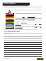
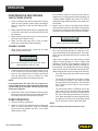
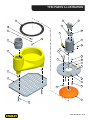
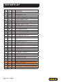
TP03 HYDRAULIC TRASH PUMP Safety, Operation and Maintenance USER MANUAL © 2012 Stanley Black & Decker, Inc. New Britain, CT 06053 U.S.A. 58555 4/2014 Ver.10 DECLARATION OF CONFORMITY DECLARATION OF CONFORMITY ÜBEREINSTIMMUNGS-ERKLARUNG DECLARATION DE CONFORMITE CEE DECLARACION DE CONFORMIDAD DICHIARAZIONE DI CONFORMITA Hydraulic Tools ______________________________________________________________________ I, the undersigned: Ich, der Unterzeichnende: Je soussigné: El abajo firmante: lo sottoscritto: Weisbeck, Andy Surname and First names/Familiennname und Vornamen/Nom et prénom/Nombre y apellido/Cognome e nome hereby declare that the equipment specified hereunder: bestätige hiermit, daß erklaren Produkt genannten Werk oder Gerät: déclare que l’équipement visé ci-dessous: Por la presente declaro que el equipo se especifica a continuación: Dichiaro che le apparecchiature specificate di seguito: Trash Pump, Hydraulic 1. Category: Kategorie: Catégorie: Categoria: Categoria: 2. Make/Marke/Marque/Marca/Marca 3. Type/Typ/Type/Tipo/Tipo: 4. Serial number of equipment: Seriennummer des Geräts: Numéro de série de l’équipement: Numero de serie del equipo: Matricola dell´attrezzatura: Stanley TP0300301, TP0300301D, TP0300303 All Has been manufactured in conformity with Wurde hergestellt in Übereinstimmung mit Est fabriqué conformément Ha sido fabricado de acuerdo con E’ stata costruita in conformitá con Directive/Standards Richtlinie/Standards Directives/Normes Directriz/Los Normas Direttiva/Norme No. Nr Numéro No n. Approved body Prüfung durch Organisme agréé Aprobado Collaudato EN Machinery Directive EN ISO 809:2009 2006/42/EC:2006 3744:2009 Self Self Self 5. Special Provisions: None Spezielle Bestimmungen: Dispositions particulières: Provisiones especiales: Disposizioni speciali: 6. Representative in the Union: Patrick Vervier, Stanley Dubuis 17-19, rue Jules Berthonneau-BP 3406 41034 Blois Cedex, France. Vertreter in der Union/Représentant dans l’union/Representante en la Union/Rappresentante presso l’Unione Done at/Ort/Fait à/Dado en/Fatto a Stanley Hydraulic Tools, Milwaukie, Oregon USA Signature/Unterschrift/Signature/Firma/Firma Position/Position/Fonction/Cargo/Posizione 1/5/2011 2 ► TP03 User Manual Engineering Manager Date/Datum/le/Fecha/Data 1-5-11 TABLE OF CONTENTS DECLARATION OF CONFORMITY...........................................................................................................................2 SAFETY SYMBOLS...................................................................................................................................................4 SAFETY PRECAUTIONS...........................................................................................................................................5 TOOL STICKERS & TAGS.........................................................................................................................................6 HOSE TYPES.............................................................................................................................................................7 HOSE RECOMMENDATIONS...................................................................................................................................8 FIGURE 1. TYPICAL HOSE CONNECTIONS........................................................................................................8 HTMA REQUIREMENTS............................................................................................................................................9 OPERATION.............................................................................................................................................................10 TOOL PROTECTION & CARE.................................................................................................................................12 TROUBLESHOOTING.............................................................................................................................................13 SPECIFICATIONS....................................................................................................................................................14 ACCESSORIES.......................................................................................................................................................14 TP03 PARTS ILLUSTRATION..................................................................................................................................15 TP03 PARTS LIST....................................................................................................................................................16 IMPORTANT To fill out a Product Warranty Recording form, and for information on your warranty, visit Stanleyhydraulic.com and select the Warranty tab. (NOTE: The warranty recording form must be submitted to validate the warranty). SERVICING THE STANLEY HYDRAULIC PUMP. This manual contains safety, operation, and routine maintenance instructions. Stanley Hydraulic Tools recommends that servicing of hydraulic tools, other than routine maintenance, must be performed by an authorized and certified dealer. Please read the following warning. WARNING SERIOUS INJURY OR DEATH COULD RESULT FROM THE IMPROPER REPAIR OR SERVICE OF THIS TOOL. REPAIRS AND / OR SERVICE TO THIS TOOL MUST ONLY BE DONE BY AN AUTHORIZED AND CERTIFIED DEALER. For the nearest authorized and certified dealer, call Stanley Hydraulic Tools at the number listed on the back of this manual and ask for a Customer Service Representative. TP03 User Manual ◄ 3 SAFETY SYMBOLS Safety symbols and signal words, as shown below, are used to emphasize all operator, maintenance and repair actions which, if not strictly followed, could result in a life-threatening situation, bodily injury or damage to equipment. This is the safety alert symbol. It is used to alert you to potential personal injury hazards. Obey all safety messages that follow this symbol to avoid possible injury or death. DANGER This safety alert and signal word indicate an imminently hazardous situation which, if not avoided, will result in death or serious injury. WARNING This safety alert and signal word indicate a potentially hazardous situation which, if not avoided, could result in death or serious injury. CAUTION This safety alert and signal word indicate a potentially hazardous situation which, if not avoided, could result in death or serious injury. CAUTION This signal word indicates a potentially hazardous situation which, if not avoided, may result in property damage. NOTICE This signal word indicates a situation which, if not avoided, will result in damage to the equipment. IMPORTANT This signal word indicates a situation which, if not avoided, may result in damage to the equipment. Always observe safety symbols. They are included for your safety and for the protection of the tool. LOCAL SAFETY REGULATIONS Enter any local safety regulations here. Keep these instructions in an area accessible to the operator and maintenance personnel. 4 ► TP03 User Manual SAFETY PRECAUTIONS Tool operators and maintenance personnel must always comply with the safety precautions given in this manual and on the stickers and tags attached to the tool and hose. These safety precautions are given for your safety. Review them carefully before operating the tool and before performing general maintenance or repairs. Supervising personnel should develop additional precautions relating to the specific work area and local safety regulations. If so, place the added precautions in the space provided in this manual. The models TP03 Hydraulic Trash Pump will provide safe and dependable service if operated in accordance with the instructions given in this manual. Read and understand this manual and any stickers and tags attached to the tool and hoses before operation. Failure to do so could result in personal injury or equipment damage. • Operator must start in a work area without bystanders. The operator must be familiar with all prohibited work areas such as excessive slopes and dangerous terrain conditions. • Establish a training program for all operators to ensure safe operations. • Do not operate the tool unless thoroughly trained or under the supervision of an instructor. • Always wear safety equipment such as goggles, head protection, and safety shoes at all times when operating the tool. • Do not inspect or clean the tool while the hydraulic power source is connected. Accidental engagement of the tool can cause serious injury. • Do not operate this tool without first reading the Operation section. • Do not install or remove this tool while the hydraulic power source is connected. Accidental engagement of the tool can cause serious injury. • Never operate the tool near energized transmission lines. Know the location of buried or covered services before starting work. • Do not wear loose fitting clothing when operating the tool. Loose fitting clothing can get entangled with the tool and cause serious injury. • Supply hoses must have a minimum working pressure rating of 2500 psi/175 bar. • Be sure all hose connections are tight. • The hydraulic circuit control valve must be in the “OFF” position when coupling or uncoupling the tool. Wipe all couplers clean before connecting. Failure to do so may result in damage to the quick couplers and cause overheating. Use only lint-free cloths. • Do not operate the tool at oil temperatures above 140 °F/60 °C. Operation at higher oil temperatures can cause operator discomfort and may cause damage to the tool. • Do not operate a damaged, improperly adjusted, or incompletely assembled tool. • To avoid personal injury or equipment damage, all tool repair, maintenance and service must only be performed by authorized and properly trained personnel. • Do not exceed the rated limits of the tool or use the tool for applications beyond its design capacity. • Always keep critical tool markings, such as labels and warning stickers legible. • Always replace parts with replacement parts recommended by Stanley Hydraulic Tools. • Check fastener tightness often and before each use daily. • Do not put your hands or any other body part under the volute while the trash pump is running. • Do not lift the trash pump by pulling on the hydraulic hoses. Use a suitable line fastened to the trash pump handle. • Do not point water discharge toward bystanders. TP03 User Manual ◄ 5 TOOL STICKERS & TAGS Stanley Hydraulic tools Division of the Stanley Works 3810 SE Naef Road Milwaukie, OR 97267 05152 Stanley Logo Decal 28788 Manual Decal (CE Only) 03786 GPM Decal D 30 LPM @ 138 B AR EHTMA CATEGORY 1.300 28322 CE Decal (CE Only) 11207 Circuit Type D Decal (CE Only) 28786 Coupler Decal NOTE: THE INFORMATION LISTED ON THE STICKERS SHOWN, MUST BE LEGIBLE AT ALL TIMES. REPLACE DECALS IF THEY BECOME WORN OR DAMAGED. REPLACEMENTS ARE AVAILABLE FROM YOUR LOCAL STANLEY DISTRIBUTOR. The safety tag (P/N 15875) at right is attached to the tool when shipped from the factory. Read and understand the safety instructions listed on this tag before removal. We suggest you retain this tag and attach it to the tool when not in use. D A N G E R 1. FAILURE TO USE HYDRAULIC HOSE LABELED AND CERTIFIED AS NON-CONDUCTIVE WHEN USING HYDRAULIC TOOLS ON OR NEAR ELECTRICAL LINES MAY RESULT IN DEATH OR SERIOUS INJURY. BEFORE USING HOSE LABELED AND CERTIFIED AS NONCONDUCTIVE ON OR NEAR ELECTRIC LINES BE SURE THE HOSE IS MAINTAINED AS NON-CONDUCTIVE. THE HOSE SHOULD BE REGULARLY TESTED FOR ELECTRIC CURRENT LEAKAGE IN ACCORDANCE WITH YOUR SAFETY DEPARTMENT INSTRUCTIONS. 2. A HYDRAULIC LEAK OR BURST MAY CAUSE OIL INJECTION INTO THE BODY OR CAUSE OTHER SEVERE PERSONAL INJURY. A. DO NOT EXCEED SPECIFIED FLOW AND PRESSURE FOR THIS TOOL. EXCESS FLOW OR PRESSURE MAY CAUSE A LEAK OR BURST. B. DO NOT EXCEED RATED WORKING PRESSURE OF HYDRAULIC HOSE USED WITH THIS TOOL. EXCESS PRESSURE MAY CAUSE A LEAK OR BURST. C. CHECK TOOL HOSE COUPLERS AND CONNECTORS DAILY FOR LEAKS. DO NOT FEEL FOR LEAKS WITH YOUR HANDS. CONTACT WITH A LEAK MAY RESULT IN SEVERE PERSONAL INJURY. D A N G E R D. DO NOT LIFT OR CARRY TOOL BY THE HOSES. DO NOT ABUSE HOSE. DO NOT USE KINKED, TORN OR DAMAGED HOSE. 3. MAKE SURE HYDRAULIC HOSES ARE PROPERLY CONNECTED TO THE TOOL BEFORE PRESSURING SYSTEM. SYSTEM PRESSURE HOSE MUST ALWAYS BE CONNECTED TO TOOL “IN” PORT. SYSTEM RETURN HOSE MUST ALWAYS BE CONNECTED TO TOOL “OUT” PORT. REVERSING CONNECTIONS MAY CAUSE REVERSE TOOL OPERATION WHICH CAN RESULT IN SEVERE PERSONAL INJURY. 4. DO NOT CONNECT OPEN-CENTER TOOLS TO CLOSEDCENTER HYDRAULIC SYSTEMS. THIS MAY RESULT IN LOSS OF OTHER HYDRAULIC FUNCTIONS POWERED BY THE SAME SYSTEM AND/OR SEVERE PERSONAL INJURY. 5. BYSTANDERS MAY BE INJURED IN YOUR WORK AREA. KEEP BYSTANDERS CLEAR OF YOUR WORK AREA. 6. WEAR HEARING, EYE, FOOT, HAND AND HEAD PROTECTION. 7. TO AVOID PERSONAL INJURY OR EQUIPMENT DAMAGE, ALL TOOL REPAIR MAINTENANCE AND SERVICE MUST ONLY BE PERFORMED BY AUTHORIZED AND PROPERLY TRAINED PERSONNEL. I M P O R T A N T I M P O R T A N T READ OPERATION MANUAL AND SAFETY INSTRUCTIONS FOR THIS TOOL BEFORE USING IT. READ OPERATION MANUAL AND SAFETY INSTRUCTIONS FOR THIS TOOL BEFORE USING IT. USE ONLY PARTS AND REPAIR PROCEDURES APPROVED BY STANLEY AND DESCRIBED IN THE OPERATION MANUAL. USE ONLY PARTS AND REPAIR PROCEDURES APPROVED BY STANLEY AND DESCRIBED IN THE OPERATION MANUAL. TAG TO BE REMOVED ONLY BY TOOL OPERATOR. TAG TO BE REMOVED ONLY BY TOOL OPERATOR. SEE OTHER SIDE SEE OTHER SIDE SAFETY TAG P/N 15875 (Shown smaller then actual size) 6 ► TP03 User Manual HOSE TYPES The rated working pressure of the hydraulic hose must be equal to or higher than the relief valve setting on the hydraulic system. There are three types of hydraulic hose that meet this requirement and are authorized for use with Stanley Hydraulic Tools. They are: Certified non-conductive — constructed of thermoplastic or synthetic rubber inner tube, synthetic fiber braid reinforcement, and weather resistant thermoplastic or synthetic rubber cover. Hose labeled certified nonconductive is the only hose authorized for use near electrical conductors. Wire-braided (conductive) — constructed of synthetic rubber inner tube, single or double wire braid reinforcement, and weather resistant synthetic rubber cover. This hose is conductive and must never be used near electrical conductors. Fabric-braided (not certified or labeled non-conductive) — constructed of thermoplastic or synthetic rubber inner tube, synthetic fiber braid reinforcement, and weather resistant thermoplastic or synthetic rubber cover. This hose is not certified non-conductive and must never be used near electrical conductors. HOSE SAFETY TAGS To help ensure your safety, the following DANGER tags are attached to all hose purchased from Stanley Hydraulic Tools. DO NOT REMOVE THESE TAGS. If the information on a tag is illegible because of wear or damage, replace the tag immediately. A new tag may be obtained from your Stanley Distributor. D A N G E R D A N G E R 1. FAILURE TO USE HYDRAULIC HOSE LABELED AND CERTIFIED AS NON-CONDUCTIVE WHEN USING HYDRAULIC TOOLS ON OR NEAR ELECTRIC LINES MAY RESULT IN DEATH OR SERIOUS INJURY. FOR PROPER AND SAFE OPERATION MAKE SURE THAT YOU HAVE BEEN PROPERLY TRAINED IN CORRECT PROCEDURES REQUIRED FOR WORK ON OR AROUND ELECTRIC LINES. 2. BEFORE USING HYDRAULIC HOSE LABELED AND CERTIFIED AS NON-CONDUCTIVE ON OR NEAR ELECTRIC LINES. WIPE THE ENTIRE LENGTH OF THE HOSE AND FITTING WITH A CLEAN DRY ABSORBENT CLOTH TO REMOVE DIRT AND MOISTURE AND TEST HOSE FOR MAXIMUM ALLOWABLE CURRENT LEAKAGE IN ACCORDANCE WITH SAFETY DEPARTMENT INSTRUCTIONS. 3. DO NOT EXCEED HOSE WORKING PRESSURE OR ABUSE HOSE. IMPROPER USE OR HANDLING OF HOSE COULD RESULT IN BURST OR OTHER HOSE FAILURE. KEEP HOSE AS FAR AWAY AS POSSIBLE FROM BODY AND DO NOT PERMIT DIRECT CONTACT DURING USE. CONTACT AT THE BURST CAN CAUSE BODILY INJECTION AND SEVERE PERSONAL INJURY. 4. HANDLE AND ROUTE HOSE CAREFULLY TO AVOID KINKING, ABRASION, CUTTING, OR CONTACT WITH HIGH TEMPERATURE SURFACES. DO NOT USE IF KINKED. DO NOT USE HOSE TO PULL OR LIFT TOOLS, POWER UNITS, ETC. 5. CHECK ENTIRE HOSE FOR CUTS CRACKS LEAKS ABRASIONS, BULGES, OR DAMAGE TO COUPLINGS IF ANY OF THESE CONDITIONS EXIST, REPLACE THE HOSE IMMEDIATELY. NEVER USE TAPE OR ANY DEVICE TO ATTEMPT TO MEND THE HOSE. 6. AFTER EACH USE STORE IN A CLEAN DRY AREA. SEE OTHER SIDE SIDE 1 SEE OTHER SIDE (Shown smaller than actual size) DO NOT REMOVE THIS TAG DO NOT REMOVE THIS TAG THE TAG SHOWN BELOW IS ATTACHED TO “CERTIFIED NON-CONDUCTIVE” HOSE SIDE 2 D A N G E R D A N G E R 1. DO NOT USE THIS HYDRAULIC HOSE ON OR NEAR ELECTRIC LINES. THIS HOSE IS NOT LABELED OR CERTIFIED AS NON-CONDUCTIVE. USING THIS HOSE ON OR NEAR ELECTRICAL LINES MAY RESULT IN DEATH OR SERIOUS INJURY. 5. CHECK ENTIRE HOSE FOR CUTS CRACKS LEAKS ABRASIONS, BULGES, OR DAMAGE TO COUPLINGS IF ANY OF THESE CONDITIONS EXIST, REPLACE THE HOSE IMMEDIATELY. NEVER USE TAPE OR ANY DEVICE TO ATTEMPT TO MEND THE HOSE. 2. FOR PROPER AND SAFE OPERATION MAKE SURE THAT YOU HAVE BEEN PROPERLY TRAINED IN CORRECT PROCEDURES REQUIRED FOR WORK ON OR AROUND ELECTRIC LINES. 6. AFTER EACH USE STORE IN A CLEAN DRY AREA. 3. DO NOT EXCEED HOSE WORKING PRESSURE OR ABUSE HOSE. IMPROPER USE OR HANDLING OF HOSE COULD RESULT IN BURST OR OTHER HOSE FAILURE. KEEP HOSE AS FAR AWAY AS POSSIBLE FROM BODY AND DO NOT PERMIT DIRECT CONTACT DURING USE. CONTACT AT THE BURST CAN CAUSE BODILY INJECTION AND SEVERE PERSONAL INJURY. 4. HANDLE AND ROUTE HOSE CAREFULLY TO AVOID KINKING, CUTTING, OR CONTACT WITH HIGH TEMPERATURE SURFACES. DO NOT USE IF KINKED. DO NOT USE HOSE TO PULL OR LIFT TOOLS, POWER UNITS, ETC. DO NOT REMOVE THIS TAG DO NOT REMOVE THIS TAG THE TAG SHOWN BELOW IS ATTACHED TO “CONDUCTIVE” HOSE. SEE OTHER SIDE SEE OTHER SIDE SIDE 1 SIDE 2 (Shown smaller than actual size) TP03 User Manual ◄ 7 8 ► TP03 User Manual All hydraulic hose must meet or exceed specifications as set forth by SAE J517. All hydraulic hose must have at least a rated minimum working pressure equal to the maximum hydraulic system relief valve setting. This chart is intended to be used for hydraulic tool applications only based on Stanley Hydraulic Tools tool operating requirements and should not be used for any other applications. The chart to the right shows recommended minimum hose diameters for various hose lengths based on gallons per minute (gpm)/ liters per minute (lpm). These recommendations are intended to keep return line pressure (back pressure) to a minimum acceptable level to ensure maximum tool performance. Tool to Hydraulic Circuit Hose Recommendations METERS INCH MM Inside Diameter USE (Press/Return) PSI up to 10 up to 3 3/8 10 Both 2250 49-60 49-60 13-16 13-16 FLOW >>> RETURN <<< FLOW PRESSURE 26-100 up to 25 100-200 51-100 up to 50 100-300 51-100 8-30 up to 8 30-60 15-30 up to 15 30-90 15-30 up to 15 7.5-30 up to 7.5 Figure 1. Typical Hose Connections 38-49 10-13 38-49 10-13 38-49 19-40 5-10.5 10-13 19-40 5-10.5 up to 50 26-100 15-23 19-40 4-6 up to 25 15-23 16 19 19 25.4 16 19 19 25.4 5/8 3/4 3/4 1 5/8 3/4 3/4 1 16 19 3/4 5/8 16 16 5/8 13 13 10 5/8 1/2 1/2 3/8 Return Pressure Return Pressure Return Pressure Return Pressure Both Return Pressure Both Both Both Both 2500 2500 2500 2500 2500 2500 2500 2500 2500 2500 2500 2500 2500 2500 2500 175 175 175 175 175 175 175 175 175 175 175 175 175 175 175 155 BAR Min. Working Pressure Certified Non-Conductive Hose - Fiber Braid - for Utility Bucket Trucks FEET Hose Lengths Conductive Hose - Wire Braid or Fiber Braid -DO NOT USE NEAR ELECTRICAL CONDUCTORS 15-34 LPM 5-10.5 4-6 4-9 GPM Oil Flow HOSE RECOMMENDATIONS HTMA / EHTMA REQUIREMENTS HTMA / EHTMA REQUIREMENTS HTMA HYDRAULIC SYSTEM REQUIREMENTS TYPE I Nominal Operating Pressure (at the power supply outlet) 4-6 gpm (15-23 lpm) 1500 psi (103 bar) TOOL TYPE TYPE II TYPE RR 7-9 gpm (26-34 lpm) 1500 psi (103 bar) 9-10.5 gpm (34-40 lpm) 1500 psi (103 bar) System relief valve setting (at the power supply outlet) 2100-2250 psi (145-155 bar) 2100-2250 psi (145-155 bar) 2200-2300 psi (152-159 bar) 2100-2250 psi (145-155 bar) Maximum back pressure (at tool end of the return hose) 250 psi (17 bar) 250 psi (17 bar) 250 psi (17 bar) 250 psi (17 bar) Measured at a max. fluid viscosity of: (at min. operating temperature) 400 ssu* 400 ssu* 400 ssu* 400 ssu* (82 centistokes) (82 centistokes) (82 centistokes) (82 centistokes) Temperature: Sufficient heat rejection capacity to limit max. fluid temperature to: (at max. expected ambient temperature) 140° F (60° C) Flow Range 140° F (60° C) 140° F (60° C) TYPE III 11-13 gpm (42-49 lpm) 1500 psi (103 bar) 140° F (60° C) 3 hp 5 hp 6 hp 7 hp Min. cooling capacity at a temperature (2.24 kW) (3.73 kW) (5.22 kW) (4.47 kW) difference of between ambient and fluid 40° F 40° F 40° F 40° F temps (22° C) (22° C) (22° C) (22° C) NOTE: Do not operate the tool at oil temperatures above 140° F (60° C). Operation at higher temperatures can cause operator discomfort at the tool. Filter Min. full-flow filtration Sized for flow of at least: (For cold temp. startup and max. dirt-holding capacity) 25 microns 30 gpm (114 lpm) Hydraulic fluid Petroleum based (premium grade, anti-wear, non-conductive) Viscosity (at min. and max. operating temps) 100-400 ssu* 25 microns 30 gpm (114 lpm) 25 microns 30 gpm (114 lpm) 100-400 ssu* 100-400 ssu* (20-82 centistokes) 25 microns 30 gpm (114 lpm) 100-400 ssu* NOTE: When choosing hydraulic fluid, the expected oil temperature extremes that will be experienced in service determine the most suitable temperature viscosity characteristics. Hydraulic fluids with a viscosity index over 140 will meet the requirements over a wide range of operating temperatures. *SSU = Saybolt Seconds Universal EHTMA HYDRAULIC SYSTEM REQUIREMENTS CLASSIFICATION B C D Nominal Operating Pressure (at the power supply outlet) 3.5-4.3 gpm (13.5-16.5 lpm) 1870 psi (129 bar) 4.7-5.8 gpm (18-22 lpm) 1500 psi (103 bar) 7.1-8.7 gpm (27-33 lpm) 1500 psi (103 bar) 9.5-11.6 gpm (36-44 lpm) 1500 psi (103 bar) 11.8-14.5 gpm (45-55 lpm) 1500 psi (103 bar) System relief valve setting (at the power supply outlet) 2495 psi (172 bar) 2000 psi (138 bar) 2000 psi (138 bar) 2000 psi (138 bar) 2000 psi (138 bar) Flow Range NOTE: These are general hydraulic system requirements. See tool specification page for tool specific requirements TP03 User Manual ◄ 9 OPERATION PREOPERATION PROCEDURES CHECK POWER SOURCE 1. Using a calibrated flow meter and pressure gauge, make sure the hydraulic power source develops a flow of 7–9 gpm/26–34 Ipm at 1500–2000 psi/105– 140 bar. 2. Make certain that the power source is equipped with a relief valve set to open at 2150–2250 psi/150–155 bar maximum. Do not attach a nozzle to the outlet end of the discharge hose. For high-pressure water pumping, use a Stanley SM20 or SM50 and nozzle. The TP03 is designed for high GPM water flow at low water pressure (head). 3. Attach a rope or cable to the trash pump’s handle. Lower the trash pump into the liquid to be pumped. Do not raise or lower the trash pump by its hoses or couplers to avoid damage to the hoses or couplers. 3. Make certain that the power source return pressure does not exceed 250 psi/17 bar. IMPORTANT 4. Make sure the trash pump inlet is clear of debris. Remove any obstruction before operating. Never point the hose at bystanders. CONNECT HOSES 1. Wipe all hose couplers with a clean lint free cloth before making connections. IMPORTANT Do not connect pressure to the return port. Motor shaft seal limit Is 250 psi/17 bar. 2. Connect the hoses from the hydraulic power source to the couplers on the trash pump or trash pump hoses. It is a good practice to connect return hose first and disconnect it last to minimize or avoid trapped pressure within the trash pump motor. NOTE: If uncoupled hoses are left in the sun, pressure increase inside the hoses might make them difficult to connect. Whenever possible, connect the free ends of the hoses together. 4. Turn on the hydraulic power source. Watch for solids in the liquid being pumped. If solids are excessive, the discharge flow might decrease. If this happens, stop the pump and check for the cause of the problem. Under some conditions, the liquid being pumped might be slowed enough so it can no longer push particles in the liquid. If this happens, particles can accumulate in the pumping chamber, causing further restriction. The impeller then acts as a “grinding wheel” which causes accelerated trash pump wear. Reduced liquid flow can be caused by the following: • The trash pump sinks into solids at the bottom of the hole. • The end of the outlet hose is too high, causing an excessive lift height for the column of liquid being pushed by the trash pump. This slows the flow of liquid to a level where it can no longer carry solids. • The flow and pressure of hydraulic fluid to the trash pump is too low, which reduces impeller speed. A 20 percent decrease in hydraulic fluid flow can reduce pump performance by 50 percent. When operating at reduced hydraulic flow and pressure, the end of the outlet hose should not be more than 30 ft/9 m above the liquid. 3. Observe the arrow on the couplers to ensure that the flow is in the proper direction. The female coupler on the trash pump is the inlet (pressure) coupler. PUMP OPERATION 1. Observe all safety precautions. 2. Attach a 3-inch/76 mm diameter hose to the pump outlet. For best performance, keep the discharge hose as short as possible and lay it out to avoid sharp bends or kinks. 10 ► TP03 User Manual NOTE: It will not damage the pump to operate it “dry.” OPERATION 5. When pumping is complete, set the hydraulic control valve to the “OFF” position. Lift the trash pump from the work area using the rope or cable to avoid damage to the hoses or couplers. IMPORTANT Observe the following for trash pump protection and care. COLD WEATHER OPERATION If the trash pump is to be used during cold weather, preheat the hydraulic fluid at low power source speed. When using the normally recommended fluids, fluid should be at or above 50 °F/10 °C (400 ssu/82 centistokes) before use. Damage to the hydraulic system or pump motor seals can result from use with fluid that is too viscous or thick. 6. The trash pump must maintain a minimum impeller speed in order to move solid particles through the pump. While pumping liquids containing large solids, monitor the flow from the outlet of the fire hose. If it begins to slow, turn off the hydraulic power source and lift the trash pump from the work area. Disconnect the hydraulic hoses and clean at the water hose and the pumping chamber. IMPORTANT Pumping liquids with a solids-to liquid ratio greater than 30 percent solids to 70 percent liquid will cause accelerated impeller wear. 7. To maintain optimum performance, it is good practice to periodically inspect the impeller for wear or damage. This is especially important following the pumping of liquids containing sharp, abrasive solids. TP03 User Manual ◄ 11 TOOL PROTECTION & CARE NOTICE In addition to the Safety Precautions found in this manual, observe the following for equipment protection and care. • Make sure all couplers are wiped clean before connection. • Always keep critical tool markings, such as warning stickers and tags legible. • The hydraulic circuit control valve must be in the “OFF” position when coupling or uncoupling hydraulic tools. Failure to do so may result in damage to the quick couplers and cause overheating of the hydraulic system. • Tool repair should be performed by experienced personnel only. • Make certain that the recommended relief valves are installed in the pressure side of the system. • Do not use the tool for applications for which it was not intended. • Always store the tool in a clean dry space, safe from damage or pilferage. • Make sure the circuit PRESSURE hose (with male quick disconnect) is connected to the “IN” port. The circuit RETURN hose (with female quick disconnect) is connected to the opposite port. Do not reverse circuit flow. This can cause damage to internal seals. • Always replace hoses, couplings and other parts with replacement parts recommended by Stanley Hydraulic Tools. Supply hoses must have a minimum working pressure rating of 2500 psi/172 bar. • Do not exceed the rated flow or pressure (refer to Specifications in this manual for correct flow rate and pressure). If specifications are exceeded, rapid failure of the internal seals may result. 12 ► TP03 User Manual TROUBLESHOOTING If symptoms of poor performance develop, the following chart can be used as a guide to correct the problem. When diagnosing faults in operation of the tool, always make sure the hydraulic power source is supplying the correct hydraulic flow and pressure as listed in the table. Use a flowmeter know to be accurate. Check the flow with the hydraulic fluid temperature at least 80 °F/27 °C. PROBLEM Pump will not start. Poor pump performance. CAUSE SOLUTION No hydraulic fluid flow or pressure. Turn on power unit and check that 7–9 gpm/26– 34 lpm at 1500–2000 psi/105–140 bar is available at the trash pump. Defective couplers. Check the couplers by connecting them together with the hydraulic power supply operating and with the control valve in the “ON” position. The power supply should operate without “loading” from the couplers. Impeller jammed with debris. Clean the pumping chamber. Impeller rubbing against wear plates. Check and adjust the impeller clearance. Defective power module. Repair or replace the power module. Hydraulic flow reversed. Check that the hoses are correctly connected to the pump motor ports. The female coupler should be connected to the “IN” port. The return fluid must never flow through a reversing valve. Improper hydraulic fluid flow. Check that 7–9 gpm/26–34 lpm at 1500–2000 psi/105–140 bar is available at the trash pump. A 20% decrease in flow can result in a 50% decrease in pump performance. 8 gpm/30 lpm is the best circuit flow. Trash pump submersed in sediment. Lift the pump from the bottom of the hole or chamber. Use a flat support under the pump if necessary. Trash pump inlet restricted. Remove restriction and thoroughly clean. Discharge hose kinked or restricted. Straighten the hoes. If the hose must bend at the top of the hole, use a piece of split rigid conduit with large diameter of the expanded hose. This keeps the hose from kinking. Use a 90° 3-inch pipe elbow on the trash pump outlet if necessary. Discharge hose too small. Use a 3-inch diameter hose. Water lift too high. Lower the outlet end of the discharge hose. Impeller worn or damaged. Check impeller for damage and excessive wear. Replace if necessary. Wear plates worn or damaged. Check wear plates for damage and excessive wear. Replace if necessary. Hydraulic fluid in discharge flow. Motor shaft seal failure. Replace the motor shaft seal. Ensure power unit is delivering 7–9 gpm/26–34 lpm TP03 User Manual ◄ 13 SPECIFICATIONS Capacity......................................................................................................................................... 450 gpm/1688 lpm Weight.......................................................................................................................................................31 lbs/14 kg Height (over handle).............................................................................................................................. 16.5 in./42 cm Length................................................................................................................................................... 14 in./35.5 cm Width........................................................................................................................................................ 16 in./41 cm Pressure.......................................................................................................................... 1500–2000 psi/105–140 bar Flow Range.................................................................................................................................. 7–9 gpm/26–34 lpm Maximum Flow....................................................................................................................................... 9 gpm/34 lpm Porting......................................................................................................................................................1/2 in. NPTF Connect Size and Type..................................................................................................................... 1/2 in. Male Pipe Discharge Diameter................................................................................................................. 3 in./76.2 mm Camlock Inlet Diameter......................................................................................................................................... 3 in./76.2 mm System Type....................................................................................................................................OC, HTMA Type II HTMA Class II............................................................................................................................ 7–-9 gom @ 2000 psi EHTMA Category............................................................................................................................ 30 lpm @ 138 bar Sound Pressure....................................................................................................................................<85 dBA @ 1m Vibration Level........................................................................................................................................................ N/A ACCESSORIES Description Part No. Adapter, 3 in. NPT/3 in. Camlock Male..............................................................................................................52720 Lay-Flat Discharge Hose, 3 in. × 25 ft with Camlock Fittings.............................................................................56761 14 ► TP03 User Manual TP03 PARTS ILLUSTRATION 10 5 4 8 18 2 25 21 13 19 26 6 1 16 27 15 14 22 7 20 24 12 11 3 28 17 9 23 TP03 User Manual ◄ 15 TP03 PARTS LIST ITEM NO. PART NO. QTY DESCRIPTION 1 00635 1 Key 2 01324 1 LOCKWASHER 1/4" I.D. 3 03786 1 GPM STICKER 4 03975 1 COUPLER,3/8 FEM 1/2NPT 5 03976 1 COUPLER,3/8MALE 1/2NPT 6 04353 2 NYLOCK NUT 3/8-16UNC 7 05152 1 STANLEY STICKER 8 06264 1 ADAPTER -12 SAE X 1/2 NPT 9 07200 1 IMPELLER ASSY 10 07201 1 TP03 GASKET 11 73356 1 MOTOR ADAPTOR PLATE 12 07206 1 BASE PLATE 13 09661 1 HHCS 1/4-28UNF X .750 SST 14 11207 1 CIRCUIT TYPE "D" STICKER 15 19534 6 HEX FLANGE BOLT 3/8-16 X 1 16 73067 1 URETHANE BOWL YELLOW 51301 1 URETHANE BOWL TP0300303 ARMY MODEL ONLY 17 21978 2 CAPSCREW 3/8-16 X 1.75 18 22294 1 WASHER 1"OD X 1/4 ID SST 19 24381 1 HYDRAULIC MOTOR 20 28322 1 STICKER "CE" 25MM 21 28786 1 COUPLER STICKER 22 28788 1 STICKER - MANUAL 23 38701 3 CAPSCREW 1/2-13 X 2.5 24 38702 3 HEX JAM NUT 1/2-13UNC 25 39426 1 ADAPTER -14 SAE X 1/2 NPT 26 52720 1 CAMLOCK COUPLING 3" 27 73058 1 LIFTING EYE NUT 3/8-16 28 73061 1 CAPSCREW 3/8-16 X 1 66401 1 SEAL KIT (JIHOSTRO BRAND MOTOR ONLY) FOR P/N-24381 MOTOR 26230 1 SEAL KIT (CASAPPA BRAND MOTOR ONLY) 73434 1 OUTPUT SHAFT FOR P/N-24381 MOTOR ONLY 03974 1 COUPLER SET (MALE & FEMALE) 16 ► TP03 User Manual Stanley Hydraulic Tools 3810 SE Naef Road Milwaukie, Oregon 97267-5698 USA (503) 659-5660 / Fax (503) 652-1780 www.stanleyhydraulic.com