1
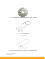
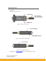
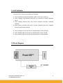
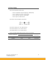
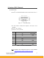
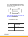
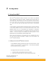
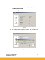
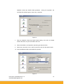
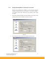
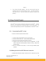
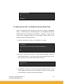
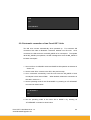
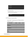
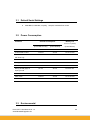
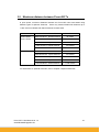
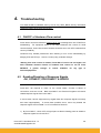
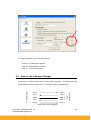
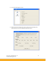
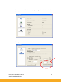
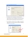
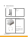
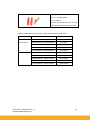
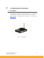
Promi-SD™
User Manual
Version 1.3
by Bluetooth
Enabling Wireless Serial Communications
HANTZ
+ PARTNER
The Upgrade Company! www.hantz.com
Promi-SD™ User Manual ver 1.3
www.initium.co.kr
Deutschland:
Tel.: 0761 / 592100
Fax: 0761 / 585228
Schweiz:
Tel.: 061 / 27311-31
Fax: 061 / 27311-39
Österreich:
Tel.: 01 / 5 85 54-30
Fax: 01 / 5 85 54-60
1
Revision History: User Manual of Promi-SD™
Version
Changed Contents
Date
1.1
Draft version
01/02/2003
1.2
Added Technical Specifications/Troubleshooting.
06/14/2003
1.3
Amended Power Consumption data of Promi-SD101/102/202
06/24/2003
Promi-SD™ User Manual ver 1.3
www.BluetoothUpgrades.de
2
Contents
1. Product Description .........................................5
1.1
About Promi-SD™....................................................................................................... 5
1.2
External View ............................................................................................................... 8
1.3
LED Indicator ............................................................................................................... 9
1.4
Block Diagram ............................................................................................................. 9
1.5
Power Supply............................................................................................................. 10
1.6
Interface- RS232 / Bluetooth ..................................................................................... 11
1.6.1
RS232 Interface
11
1.6.2
Bluetooth Interface
12
2. Configuration ..................................................13
2.1
2.2.
Using Promi-WIN™ ................................................................................................... 13
2.1.1
Making the first Promi-SDTM/Bluetooth connection
13
2.1.2
Setting Operating Mode for Automatic Connection
17
Using a Terminal Program ........................................................................................ 18
2.2.1
Connecting Promi-SD™ to host.
18
2.2.2
Making the first Promi-SD™/Bluetooth connection
18
2.2.3
Making Promi-SD™ do INQUIRY SCAN and PAGE SCAN
20
2.2.4
Releasing the existing Bluetooth connection
21
2.2.5
Automatic connection of two Promi-SD™ Units
22
2.2.6
AT command vs. Operational Status
23
3. Technical Specifications ................................24
3.1
Default Serial Settings ............................................................................................... 25
3.2
Power Consumption .................................................................................................. 25
3.3
Environmental............................................................................................................ 25
3.4
Serial Interface........................................................................................................... 26
3.5
Maximum distance between Promi-SD™s ................................................................ 27
4. Troubleshooting..............................................28
4.1
ON/OFF of Hardware Flow control ............................................................................ 28
Promi-SD™ User Manual ver 1.3
www.BluetoothUpgrades.de
3
4.2
Enabling/Disabling of Response Signals................................................................... 28
-OK, CONNECT, DISCONNECT & ERROR ............................................................. 28
4.3
How to use a Gender Changer.................................................................................. 29
4.4
Hardware Reset......................................................................................................... 30
4.5
How to get Bluetooth CF cards connected to Promi-SD ........................................... 30
5.
Optional Antennas .........................................34
6. About New Products ......................................36
6.1
7.
Promi-SD202............................................................................................................. 36
For Multi-Serial Connections ........................37
7.1
Promi-MSP™ ............................................................................................................ 37
8. Legal Notice ....................................................38
9. About this Manual...........................................40
Appendix A: Power Adaptor Specification .........41
Appendix B: AT command sets ...........................44
Promi-SD™ User Manual ver 1.3
www.BluetoothUpgrades.de
4
1.
Product Description
1.1 About Promi-SD™
Promi-SD™ is developed for long range, easy-to-install, low-cost, wireless serial
communications.
Provided is point-to-point wireless connection without standard
RS232 cables.
For point-to-multipoint connections, please refer to our Promi-MSP™, providing all
the features of RS485.
Product line
Model Name
Part No.
Spec.
Promi-SD101
PSD00-10100
Class 2 / Output Power: 2.5mW (4dBm)
5V DC power supply
Rechargeable Li-poly Battery, internal
w/ Power Adapter
w/ Setup Software & manual on CD
Promi-SD102
PSD00-10200
Class 2 / Output Power: 2.5mW (4dBm)
5V/12V DC power supply
w/o Battery & Power Adapter
w/ Setup Software & manual on CD
w/ USB Power Cable & DC Power Cable
(Optional: 5V Power Adapter)
Promi-SD202
PSD00-20200
Class 1 / Output Power: 63mW (18dBm)
5V DC power supply
w/o Battery & Power Adapter
w/ Setup Software & manual on CD
w/ USB Power Cable & DC Power Cable
(Optional: 5V Power Adapter)
Promi-SD™ User Manual ver 1.3
wwwBluetoothUpgrades.de
5
Fig. 1.1.1 A CD-ROM inclusive a setup software (Promi-WIN™) and user manual
Fig. 1.1.2 Optional Power Adaptor
Part no. PSD00-00010
Fig. 1.1.3 USB Power Adaptor
Part no. PSD00-00020
*You may use USB port to supply power to Promi-SD™ using this USB power cable
Promi-SD™ User Manual ver 1.3
wwwBluetoothUpgrades.de
6
Fig. 1.1.4 DC Power Cable
Part no. PSD00-00030
*Red colored line of DC power cable is for ‘+’
Promi-SD™ User Manual ver 1.3
wwwBluetoothUpgrades.de
7
1.2 External View
Promi-SD™
Dimensions: 60 x 26 x 16 (mm)
STATUS LED
STUB ANTENNA
P/N: PSD00-00040
POWER LED
TM
Figure 1.2.1 Promi-SD
top view
ON/OFF SWITCH
HARD RESET SWITCH
Figure 1.2.2 Promi-SDTM right side view
DC Connector
Figure 1.2.3 Promi-SDTM left side view
Please refer to the 1.5 Power Supply section for Promi-SD™ power options
Promi-SD™ User Manual ver 1.3
www.BluetoothUpgrades.de
8
1.3 LED Indicator
The Promi-SD™ STATUS LED indicates the following:
z
Amber STATUS LED indicates standard mode on Promi-SD™ power-up.
z
Green STATUS LED indicates Promi-SD™ is connected to another Bluetooth
device
z
Green flashing STATUS LED every second indicates Promi-SD™ INQUIRY
operation
z
Green flashing STATUS LED every 3 seconds indicates Promi-SD™ INQUIRY
SCAN or PAGE SCAN operation
z
Amber POWER LED of Promi-SD101 indicates battery is being charged.
z
Green POWER LED of Promi-SD101 indicates battery is fully charged.
z
Green POWER LED of Promi-SD102 indicates power is being supplied.
1.4 Block Diagram
Promi-SD™ User Manual ver 1.3
wwwBluetoothUpgrades.de
9
1.5 Power Supply
Power may be supplied by following ways:
-
Power via a standard AC-plug DC-adapter (p/n: PSD00-00010)
-
Power via USB power cable (p/n: PSD00-00020)
-
Power via DC power cable (p/n: PSD00-00030)
-
Power via pin 9 of D-SUB connector.
Promi-SD101 can be recharged by 4 ways above.
Figure 1.5.1. DC plug polarity
Promi-SD101 (Class2): 5V+/-10%, 500mA minimum
Promi-SD102 (Class2): 4V~12V, 100mA minimum
Promi-SD202 (Class1): 4V~12V, 150mA minimum
Current Consumption Data at different speeds of serial communications:
Condition of Baud Rate
Current Consumption
Battery Life
(Promi-SD101/102)
(Promi-SD202)
(Promi-SD101)
9600bps
35.3 mA
40 mA
5 hrs 20 min
115200bps
40 mA
72 mA
4 hrs 30 min.
Promi-SD™ User Manual ver 1.3
wwwBluetoothUpgrades.de
10
1.6 Interface- RS232 / Bluetooth
1.6.1 RS232 Interface
Promi-SDTM has a 9-PIN DSUB (female) connector as shown below in Fig 1.7.1.
Figure 1.7.1 9-PIN DSUB (Female)
z
The serial interface is RS232 DCE configured; a DTE device can be
connected.
z
Baud rate: 1200~115200 bps
z
Hardware flow control (RTS/CTS)
Pin
Signal
Direction
1
CD
Not connected
2
TxD
Output
3
RxD
Input
4
DSR
Input
5
GND
-
6
DTR
Output
7
CTS
Input
8
RTS
Output
9
Vcc
Input
Table 1.7.1. Promi-SD™ 9-PIN Specification
*NOTE: Promi-SD™ series, starting from version no. v2i will include an
Automatic Detection Feature of hardware flow control.
Promi-SD™ User Manual ver 1.3
www.BluetoothUpgrades.de
11
Promi-SD™ is designed to operate as DCE (Data Communications Equipment).
To connect to DTE (Data Terminal Equipment), for example a PC or a laptop, a
CD, 1
CD, 1
TxD, 2
RxD, 2
RxD, 3
TxD, 3
DSR, 4
DTR, 4
GND, 5
GND, 5
DTR, 6
DSR, 6
CTS, 7
RTS, 7
RTS, 8
CTS, 8
Host System (DTE)
Promi-SD (DCE)
straight cable must be used as in below.
*DTR/DSR of Promi-SD™ of v2i will be functioned for either Loop-back
operation or Communications. Users may select a function of DTR/DSR using
AT command- ATS14. Default value of ATS14 is 0.
z
ATS14=1<cr>: Users may use DTR/DSR lines for communications
z
ATS14=0<cr>: Users may use DTR/DSR lines for Loop-back only.
z
ATS14?: To see current status of ATS14.
1.6.2 Bluetooth Interface
Bluetooth Specification
V 1.1
Level
4 dBm (Promi-SD101/102)
18 dBm (Promi-SD202)
Range
~30m (Promi-SD101/102)
~100m (Promi-SD202)
Bluetooth protocols
RFCOMM, L2CAP, SDP
Supported Profiles
General Access Profile
Serial Port Profile
Promi-SD™ User Manual ver 1.3
wwwBluetoothUpgrades.de
12
2.
Configuration
2.1 Using Promi-WIN™
With PromiTM-SD, Bluetooth wireless connections can be made to any Bluetooth
device supporting SPP (Serial Port Profile).
Especially when using the SD as a
cable replacement, take advantage of the PromiTM-SD automatic connection feature.
Once a pair of SDs is set for this feature, they automatically connect when powered
up. A pair of SD units, within their radio range, may be used as a virtual RS-232
cable.
To make wireless connections between two Bluetooth devices, one device should be
in Discoverable (INQUIRY SCAN) and Connectable (PAGE SCAN) as well. Most
Bluetooth devices are set to Discoverable and Connectable in manufacture.
However, to maximize internal battery life, SD INQUIRY SCAN and PAGE SCAN are
disabled.
To make SD respond to the INQUIRY and PAGE operations of other
Bluetooth devices, activate INQUIRY SCAN and PAGE SCAN.
Before making the first Bluetooth connection with SD units, be prepared with a pair of
SD units and also install the PromiWINTM program on the CD enclosed in the
PromiTM-SD product package.
2.1.1 Making the first Promi-SDTM/Bluetooth connection
To make Bluetooth wireless connections with SD, first connect the SD to a host
computer running PromiWINTM as instructed below. Then activate SD INQUIRY
SCAN and PAGE SCAN from PromiWINTM.
Let’s suppose there are 2 Promi-SD™s, SD1 and SD2:
1.
Connect the SD1 to a host serial port and turn on the SD.
2.
Check the SD1 STATUS LED color. Amber indicates standard mode.
Promi-SD™ User Manual ver 1.3
www.BluetoothUpgrades.de
13
3.
Start the PromiWINTM configuration program by clicking the program icon
under Start/Programs/PromiWINTM.
4.
Select Promi-SD Æ Start in the menu.
SD information will be displayed as
shown in Figure 1.
Figure 1.
5.
Click the ‘Device Setting’ icon in the list control box. Set a new device name
as shown in Figure 2. Here, ‘Promi-SD1’ is used for example.
Figure 2.
6.
Click the ‘Incoming Connection’ icon in list control box. Check both options and
then click the ‘Start’ button as shown in Figure 3.
Promi-SD™ User Manual ver 1.3
www.BluetoothUpgrades.de
The SD1 now starts
14
INQUIRY SCAN and PAGE SCAN operations.
During the operation, the
STATUS LED will flash green, twice every 3 seconds.
Figure 3.
7.
After the INQUIRY SCAN and PAGE SCAN setting of the SD1 is finished
another SD, SD2, may be connected to the host.
8.
Select PromiWINTM and repeat the preceding procedure for SD2
9.
Select the ‘Connection’ icon in the list control box and click the search button.
10. Now the additional SD2 enters INQUIRY operation.
Figure 4.
Promi-SD™ User Manual ver 1.3
www.BluetoothUpgrades.de
15
11. From the ‘Search Result’ menu click the item with ‘Promi-SD1’ as its
DEVICE_NAME.
12. Once selected, its BD_ADDR will appear in the dialog box on the right side of
the ‘Connect to…’ button.
13. Click the ‘Connect to…’ button and the ‘Connection Complete’ Popup box will
appear as shown in Figure 5.
Figure 5.
14. To release the first Bluetooth wireless connection between the SD units click
the ‘Disconnect’ button.
15. For automatic connection setup, set SD1 as Mode 2 and SD2 as Mode 1.
To utilize the SD automatic connection feature, make a Bluetooth connection
between two SD units. Once connected, one SD stores the 48-bit BD_ADDR
of its counterpart.
To expedite the 48-bit BD_ADDR input operation, SD is designed to store the
BD_ADDR of its latest counterpart.
Promi-SD™ User Manual ver 1.3
www.BluetoothUpgrades.de
16
2.1.2
Setting Operating Mode for Automatic Connection
New SD units are default set to ‘MODE 0’. For SD automatic connection
change the operating mode of an SD to MODE 1 and another to MODE 2.
The following simple steps describe the SD operating mode change
procedure.
1.
After making a Bluetooth wireless connection between two SD units, set the
operating mode of one SD to MODE 1, as shown in Figure 6.
Figure 6.
2.
Set the operating mode of another SD to MODE 2 as shown below.
Promi-SD™ User Manual ver 1.3
www.BluetoothUpgrades.de
17
Figure 7.
3.
Turn off both SD power supplies.
From now, when both SD units are
powered up again, they will automatically connect. (To release this feature,
reset both SD units.
Amber SD STATUS LED indicates successful reset
process.)
2.2. Using a Terminal Program
Promi-SDTM units are easily controlled and configured via PromiWINTM . Likewise
functions are accomplished via any terminal program such as HyperTerminal. AT
command sets supported by Promi-SDTM add sophistication to Promi-SDTM control.
2.2.1
Connecting Promi-SD™ to host.
For SD use, follow the simple instructions below:
1. Connect an SD to a host serial port. Then, turn on the SD.
2. Check the STATUS LED color. Amber indicates standard mode.
3. Execute any terminal program and activate Local Echo.
4. Configure the host serial port to match the SD unit configuration. The SD
default configuration is 9600 bps Baud, 8 Data bit, No Parity, 1 Stop bit and
H/W flow control.
5. Enter ‘AT’ command at the prompt.
An SD ‘OK’ reply indicates proper
operation.
2.2.2 Making the first Promi-SD™/Bluetooth connection
As stated before, Bluetooth wireless connections can be made with any other
Promi-SD™ User Manual ver 1.3
www.initium.co.kr
18
Bluetooth device supporting Bluetooth SPP (Serial Port Profile). For Bluetooth
wireless connections to an SD, first make another SD ‘Discoverable’ and
‘Connectable’.
In this case, refer to section 3.3 before following the
instructions below.
1. First check the status of the SD by entering ‘AT+BTINFO?’. The SD
response is comprised of BD_ADDR, Device Name, Operating Mode,
Operating Status, Authentication and Encryption flags. To make connection
to other Bluetooth devices, the operating status of the first SD should be
‘STANDBY’.
A ‘PENDING’ operating status of the first SD indicates the
unit is busy with another operation. In this case, cancel the ongoing
operation by entering the ‘AT+BTCANCEL’ command.
AT+BTINFO?
000B530000A9,PSDv2g-0000A9,MODE0,STANDBY,0,0
OK
2. Search other local Bluetooth devices by entering the ‘AT+BTINQ?’ command.
AT+BTINQ?
000B53000080,PSDv2g-000080,001F00
0004B300E205,AP2002:1 #0,020300
OK
3. Check the search list.
Enter ‘ATD’ command in the BD_ADDR of any
Bluetooth device for connection.
During the connection process, the
STATUS LED will flash green every second.
4. Connection is indicated by the SD returning a ‘CONNECT’ message and
displaying a green STATUS LED.
Promi-SD™ User Manual ver 1.3
www.BluetoothUpgrades.de
19
ATD000B53000080
OK
CONNECT
2.2.3 Making Promi-SD™ do INQUIRY SCAN and PAGE SCAN
Unlike many Bluetooth serial dongles, the SD has an internal, rechargeable
battery. As stated before, to maximize battery life, the SD INQUIRY SCAN and
PAGE SCAN is set to disabled in manufacture. Therefore, to make the SD
“Discoverable” (INQUIRY SCAN) and “Connectable” (PAGE SCAN), these
operations must be manually activated.
1. Check the SD status by entering a ‘AT+BTINFO?’ command.
AT+BTINFO?
000B530000A9,PSDv2g-0000A9,MODE0,STANDBY,0,0
OK
2. Enter the ‘AT+BTSCAN’ command. The SD will start INQURY SCAN and
PAGE SCAN operation. During the process, the SD will flash twice every 3
seconds until it is connected to another Bluetooth device.
AT+BTSCAN
OK
3. Try Bluetooth connection to the SD from the other Bluetooth device. Once
connected the first SD will return the ‘CONNECT’ message and the STATUS
LED will display a continuous green without flashing.
Promi-SD™ User Manual ver 1.3
www.BluetoothUpgrades.de
20
AT+BTSCAN
OK
CONNECT
2.2.4 Releasing the existing Bluetooth connection
Once connected successfully, the SD becomes transparent to any serial
applications on hosts. Data may be transferred within the radio range of the
SD.
According to SD terminology, this operating status is called ‘ONLINE
STATUS’. In ONLINE STATUS, all AT commands are treated as characters
and are ignored by the command interpreter of the SD. Therefore to escape
from ONLINE STATUS enter escape string ‘+++’.
1. Transition from ONLINE STATUS to STANDBY STATUS by entering ‘+++’
string to the SD.
Check the current SD status by entering the
‘AT+BTINFO?’ command.
The SD status should display CONNECT
STATUS.
+++
OK
AT+BTINFO?
000B530000A9,PSDv2g-0000A9,MODE0,CONNECT,0,0
OK
2. Release the current Bluetooth connection by entering ‘ATH’ command. Once
disconnected successfully, the SD returns the ‘DISCONNECT’ message.
Promi-SD™ User Manual ver 1.3
www.BluetoothUpgrades.de
21
ATH
OK
DISCONNECT
2.2.5 Automatic connection of two Promi-SD™ Units
Two SD units connect automatically when powered up.
For automatic SD
connection first make a Bluetooth connection between two SD units. Once
connected, the SD stores the 48-bit BD_ADDR of its counterpart. To expedite
48-bit BD_ADDR input operation, the SD is designed to store the BD_ADDR of
its latest counterpart.
1. Set one SD to do INQUIRY SCAN and PAGE SCAN operation as directed in
section 3.3.
2. Set the other SD to connect to the SD in the previous step.
3. Once connected successfully, both SD units store the BD_ADDR of their
counterpart in their internal Flash. When desired, release the connection as
directed in section 3.4.
4. Set the operating mode of one SD to MODE 1 by entering an ‘AT+ BTMODE’
command as shown below.
AT+BTMODE,1
OK
5. Set the operating mode of the other SD to MODE 2 by entering an
‘AT+BTMODE’ command as show below.
Promi-SD™ User Manual ver 1.3
www.BluetoothUpgrades.de
22
AT+BTCANCEL
OK
AT+BTMODE,2
OK
6. Turn both SD units power off. The SD pair will connect automatically when
they are powered up again.
7. To release this paring, set them to MODE 0 by entering ‘AT+BTMODE, 0’. or
reset the units by pressing the RESET button.
AT+BTMODE,0
OK
2.2.6 AT command vs. Operational Status
The AT command sets listed above can be executed per Promi-SD™
operational status.
The following table shows the operational status and
executable AT command sets.
AT Command
Standby
Pending
AT<cr>
√
√
ATZ<cr>
√
√
1)
AT+BTINQ?<cr>
√
ATD112233445566<cr>
√1)
ATD<cr>
√1)
AT+BTSCAN,n<cr>
√1)
AT+BTSCAN,112233445566<cr>
√1)
√
AT+BTCANCEL<cr>
√
+++
2)
ATO<cr>
√
ATH<cr>
√2)
Promi-SD™ User Manual ver 1.3
www.BluetoothUpgrades.de
Online
23
AT+BTAUTH,Auth,Encr<cr>
AT+BTMODE,n<cr>
√3)
√3) 4)
AT+BTNAME=”Name”<cr>
√3)
AT+BTKEY=”nnnn”<cr>
√3)
ATS10=0 or ATS10=1
AT+BTINFO?<cr>
AT+UARTCONFIG,b,p,s<cr>
√
√
√3) 4)
1) Effective when Promi-SD™ is not in connection with Bluetooth.
2) Effective when Promi-SD™ is in connection status with Bluetooth.
3) Recommend to be used when Promi-SD™ is not in connections status with
Bluetooth
4) To apply new values to Promi-SD™, software reset requires by ATZ
command or restart Promi-SD™.
*NOTE: Full AT commands set can be found in Appendix B.
3.
Technical Specifications
Promi-SD™ User Manual ver 1.3
www.BluetoothUpgrades.de
24
3.1 Default Serial Settings
z
9600 Baud, 8 data bits, no parity, 1 stop bit, hardware flow control
3.2 Power Consumption
Condition
Current Consumption
Battery Life
180mA Li-Poly Battery
(Promi-SD101/102)
(Promi-SD202)
(Promi-SD101)
If NOT connected to Host
3.5 mA
19 mA
49 hrs 30 min.
If connected to Host
13.5 mA
24 mA
13 hrs 10 min
For data communications
26.5 mA
27 mA
6 hrs 50 min
During INQUIRY mode
62 mA
96 mA
3 hrs 20 min
For Master connection
63 mA
96 mA
3 hrs 10 min
During SCAN (page &
27 mA
25 mA
6 hrs 30 min.
Park mode
13.8 mA
34 mA
12 hrs 40 min
Non-Park mode
17.8 mA
40 mA
10 hrs
with Host only
inquiry) mode
3.3 Environmental
Promi-SD™ User Manual ver 1.3
www.BluetoothUpgrades.de
25
Model No.: Promi-SD101/102
Recommended operating conditions:-10’C~70’C
Humidity: 90% Non-condensing
Model No.: Promi-SD202
Recommended operating conditions: -20’C~70’C
Humidity: 90% Non-condensing
3.4 Serial Interface
Model No.: Promi-SD101
RS232, Female DSUB-9, 1200~115200 baud,
CTS/RTS flow control or no flow control
Model No.: Promi-SD102
RS232, Female DSUB-9, 1200~115200 baud,
Automatic Detection Feature of Hardware flow control
(from version PSD-v2i)
DTR/DSR for loop-back & communications
Model No.: Promi-SD202
RS232, Female DSUB-9, 1200~115200 baud,
Automatic Detection Feature of Hardware flow control
DTR/DSR for loop-back & communications
Promi-SD™ User Manual ver 1.3
www.BluetoothUpgrades.de
26
3.5 Maximum distance between Promi-SD™s
In open space, maximum distances between two Promi-SD units were tested using
different types of Optional Antennas. Users may extend wireless link distance up to
1.2Km via Promi-SD202 with Patch Antennas for both sides.
Model no.
Antennas for two Promi-SD units
Max. Distance
Promi-SD101
Default Antenna - Default Antenna
30 meters
Promi-SD102
Default Antenna - Dipole Antenna
50 meters
Dipole Antenna - Dipole Antenna
80 meters
Patch Antenna - Dipole Antenna
150 meters
Patch Antenna - Patch Antenna
300 meters
Default Antenna - Default Antenna
120 meters
Default Antenna - Dipole Antenna
150 meters
Dipole Antenna - Dipole Antenna
200 meters
Patch Antenna - Dipole Antenna
400 meters
Patch Antenna - Patch Antenna
1,200 meters
Promi-SD202
For information on optional Antennas, refer to Chapter 5 Optional Antennas.
Promi-SD™ User Manual ver 1.3
www.BluetoothUpgrades.de
27
4.
Troubleshooting
*Full FAQ list will be released soon by mid of July, 2003. Below are key information
customers need to know using Promi-SD™.
4.1 ON/OFF of Hardware Flow control
Promi-SD101 and Promi-SD102 of version v2g & v2h are designed to use CTS/RTS for
handshaking.
For equipment which is not using Hardware flow control for serial
communications, Promi-SD101/102’s firmware should be set to turn OFF hardware flow
control (CTS/RTS).
Customers may indicate preferences when ordering or turn off the handshaking by
bridging CTS and RTS (no. 7 and no. 8 lines) using a Gender changer.
*Starting from next version of models, Promi-SDs of version v2i and higher, will
have automatic detection feature of hardware flow control so can be used,
WITHOUT
a
gender
changer
to
control
CTS/RTS,
for
any
type
of
devices/equipments.
4.2 Enabling/Disabling of Response Signals
-OK, CONNECT, DISCONNECT & ERROR
Promi-SD™ will respond to users on the current status, success & failure of
connections, and error mode. Both PromiWIN™ and Terminal Programs will receive
related response signals from Promi-SD™.
In some cases, various equipment may regard these four response signals incorrectly
and react inappropriately.
To avoid these possible errors, users may disable the
response signals via PromiWIN™ or AT commands at Terminal.
1) By Promi-WIN™, check OFF at Signal pane at Device Setting panel to disable 4
response signals from Promi-SD™.
Promi-SD™ User Manual ver 1.3
www.BluetoothUpgrades.de
28
2) By AT commands at your Terminal program.
ATS10=1 : Enabling/ON 4 signals
ATS10-0 : Disabling/OFF 4 signals
ATS10? : To see current status
4.3 How to use a Gender Changer
Promi-SD™ is twisted Rx/Tx-ready for direct DTE connection. For equipments with
RxD, 2
RxD, 3
TxD, 3
GND,5
GND, 5
CTS, 7
RTS, 7
RTS, 8
CTS, 8
Host System
TxD, 2
(DTE)
Promi-SD (DCE)
female RS232 interface, please use a 1:1 Gender changer, not twisted one.
<Promi-SD™ version v2g/v2h>
Promi-SD™ User Manual ver 1.3
www.BluetoothUpgrades.de
29
4.4 Hardware Reset
For Hardware reset, press the button on the right side of the Promi-SD™ unit with a
narrow tool such as a ball-point pen.
HARD RESET SWITCH
4.5 How to get Bluetooth CF cards connected to Promi-SD
If you are using Bluetooth CF cards or USB adaptors from other manufacturers,
please use PromiWIN™ software of latest version, which will be more familiar to
consumers.
PromiWIN™ can be downloaded from our website at:
http://www.initium.co.kr/english/download.html
1) When you open the PromiWIN version2, you will get message as in below:
2) If you are going to use Promi-SD with other Bluetooth devices such as CF cards
or USB adaptors, please select 2nd option “I would like to get other Bluetooth
devices such as CF cards or USB adaptors connected to the Promi-SD”
Promi-SD™ User Manual ver 1.3
www.BluetoothUpgrades.de
30
3) You will see main page as in below:
4) Please check the Port setting information by selecting Port>Port setting menu.
Default settings of Promi-SD: 9600bps/No parity/One stop bit
Promi-SD™ User Manual ver 1.3
www.BluetoothUpgrades.de
31
5) Please select Promi-SD>Start menu, so you can get the device information from
Promi-SD.
6) Please press the button written “Make always connectable”
Promi-SD™ User Manual ver 1.3
www.BluetoothUpgrades.de
32
7) The screen of main pages will become inactive.
8) At this stage, Promi-SD™ is DICOVERABLE & CONNECTABLE MODE
Get your Bluetooth CF cards or USB adaptors connected to this Promi-SD™
now. Then you finish to connect your Bluetooth devices to Promi-SD. Open you
COM port of Serial Communication program to verify communication status.
9)
If your equipments or machines Promi-SD™ is plugged in may confuse the
Response signal from Promi-SD™ such as OK, CONNECT, DISCONNECT, &
ERROR, please turn off the Signal message. More information on the Response
messages can be found on Chater 4.1.
Promi-SD™ User Manual ver 1.3
www.BluetoothUpgrades.de
33
5.
Optional Antennas
(1) Dipole Antenna
Part No.: PSD00-00050
20dBi
Connector: SMA
Size: 10cm
(2) Patch Antenna (w/ RF extension cable & wall-attachable nails)
Part No.: PSD00-00060
Including a 30cm RF extension cable
Longer RF extension cable
Part No.: PSD00-00061: 1m length
Part No.: PSD00-00063: 3m length
Part No.: PSD00-00061: 5m length
SMA connector
Promi-SD™ User Manual ver 1.3
www.BluetoothUpgrades.de
34
Part No. : PSD00-00062
Anchor Support
*This will be needed if there is a need
to attach the Patch antenna to the wall.
*Distance Data between Promi-SD™s when Optional Antennas are used:
Model no.
Antennas for two Promi-SD units
Max. Distance
Promi-SD101
Default Antenna - Default Antenna
30 meters
Promi-SD102
Default Antenna - Dipole Antenna
50 meters
Dipole Antenna - Dipole Antenna
80 meters
Patch Antenna - Dipole Antenna
150 meters
Patch Antenna - Patch Antenna
300 meters
Default Antenna - Default Antenna
120 meters
Default Antenna - Dipole Antenna
150 meters
Dipole Antenna - Dipole Antenna
200 meters
Patch Antenna - Dipole Antenna
400 meters
Patch Antenna - Patch Antenna
1,200 meters
Promi-SD202
Promi-SD™ User Manual ver 1.3
www.BluetoothUpgrades.de
35
6.
About New Products
6.1
Promi-SD202
Promi-SD202 (part no. PSD00-20200), released from June 1, 2003, and will include
the following upgraded features:
1)
Promi-SD202 will include Class 1 Bluetooth chip, default distance: 100m;
maximum distance, via Patch antenna: 1.2Km.
2) Automatic Hardware flow control setting
3) Promi-SD202 uses Pin 1 (CD) to display Bluetooth connection status.
Pin 1 is ON if connection is active, Pin 1 is OFF if non-active.
4) Host system can automatically indicate Promi-SD202 operation status, by Pin 4
(DTR) and Pin 6 (DSR) instead of by AT commands, as Promi-SD202 loops
back status data to Host.
When Host turns on DTR signal, Promi-SD202
returns Active DSR signal to Host indicating Active operation status.
AT commands may also be used for operation status check.
5) Using Pin 4 (DTR) signal, Host may disconnect Bluetooth connections, without
AT commands. When Host changes the DTR signal to Non-active, PromiSD202 will drop the connection. AT commands may also be used for
disconnect.
Full specification of Promi-SD202 will be released soon.
Promi-SD™ User Manual ver 1.3
www.BluetoothUpgrades.de
36
7.
7.1
For Multi-Serial Connections
Promi-MSP™
For multiple serial connections, we recommend Promi-MSP™. Promi-MSP™ has
7 default Bluetooth connections and can be expanded to up to 35 connections.
More information on Promi-MSP™ can be found in its User Manual at
www.initium.co.kr
<Fig. 7.1.1 Promi-MSP™>
Promi-SD™ User Manual ver 1.3
www.BluetoothUpgrades.de
37
8.
Legal Notice
About this Document
This document provides introductory instructions on how to set up and manage
Promi-SD™ within your networking environment. Should you require more information,
please refer to Initium website at http://www.initium.co.kr.
Trademark Acknowledgements
The Bluetooth trademarks are owned by their proprietor and used by Initium Co., Ltd.
under license. Promi™ is a registered trademark of INITIUM.
Copyright Information
The unauthorized copying of materials that are covered by copyright and other
international proprietary or intellectual property rights is prohibited in most countries.
Initium Co., Ltd. recommends that the users of this equipment seek the necessary
authorizations for copying material. The instructions for use in the manual shall not be
considered as an inducement to make illicit duplications of material. Any duplication
will be made at user’s own risk.
Maintenance and Support
Every care has been taken in the preparation of this manual; if you detect any
inaccuracies or omissions, please inform us by contacting Intium’s technical support.
Initium Co., Ltd. cannot be held responsible for any technical or typographical errors
and reserves the right to make changes to the product and manuals without any prior
notice.
Limited Warranty
Promi-SD™
Initium Co., Ltd. warrants the original owner that the products delivered will be free
from defects in material and workmanship for 90 days following the date of purchase.
This warranty dose not cover any damage attributable to erroneous installation of the
product.
INITIUM’S TOTAL LIABILITY IS LIMITED TO THE PRICE/LICENSE FEE ACTUALLY
Promi-SD™ User Manual ver 1.3
www.BluetoothUpgrades.de
38
PAID BY PURCHASER TO INITIUM FOR THE PRODUCT WITH RESPECT TO
WHICH LOSSES OR DAMAGES ARE CLAIMED.
IN NO EVENT SHALL INITIUM OR ITS LICENSOR AND SUPPLIERS BE LIABLE
FOR ANY INDIRECT, INCIDENTAL OR CONSEQUENTIAL LOSSES OR DAMAGES
OF ANY NATURE WHATSOEVER, INCLUDING, BUT NOT LIMITED TO, LOSS OF
DATA OR DATA BEING RENDERED INACCURATE, LOSSES SUSTAINED BY YOU
OR THIRD PARTIES SUCH AS LOSS OF BUSINESS, LOSS OF PROFITS,
BUSINESS INTERRUPTION OR PERSONAL INJURY, EVEN IF INITIUM OR ITS
LICENSORS OR SUPPLIERS HAS BEEN ADVISED OF THE POSSIBILITY OF
SUCH DAMAGES.
This warranty does not cover replacement of products damaged by abuse, accident,
misuse, neglect, alteration, repair, disaster, improper installation or improper testing.
Promi-SD™ User Manual ver 1.3
www.BluetoothUpgrades.de
39
9.
About this Manual
This manual is available in a printable PDF version on-line and on the CD enclosed in
the Promi-SDTM product package.
For additional support related to Promi-SDTM and this document, contact INITIUM via:
HANTZ + PARTNER GMBH
Gewerbestrasse 37, D-79194 Gundelfingen
Germany
Tel: +49-761-592100
Fax: +49-761-5921039
OR
www.BluetoothUpgrades.de
OR
Email: [email protected]
Promi-SD™ User Manual ver 1.3
www.BluetoothUpgrades.de
40
Appendix A: Power Adaptor Specification
Manufacturer: Anam Instruments Inc.
Emerald B/D 7F, 1042, Hogea-dong, Dongan-gu, Anyang, Korea
Tel.: +82-31-347-6140
Fax: +82-31-347-7019
www.anamic.co.kr
Manufacturer’s Model Name: AP1015
1. STANDARD FEATURES
1.1. 10WATT AC/DC SWITCHING MODE ADAPTOR
1.2. WALL MOUNT DESIGN
1.3. 100~240Vac UNIVERSAL VOLTAGE INPUT
1.4. 5V 2A REGULATED OUTPUT
1.5. SHORT CIRCUIT PROTECTION
1.6. DESIGN TO MEET CLASS B LIMIT OF EN55022 AND FCC PART 15
1.7. VACUUM IMPREGNATED TRANSFORMER
1.8. 100% BURN-IN PROCESS
2. ELECTRICAL CHARACTERISTCS
2.1 INPUT CHARACTERISTICS
2.1.1. AC INPUT VOLTAGE
2.1.1.1. Nominal input voltage : 110 / 220 Vac
2.1.1.2. Rated input voltage range : 100 to 240 Vac
2.1.1.3. Operating input voltage range : 90 to 264 Vac
2.1.2. AC INPUT FREQUENCY
2.1.2.1. Nominal input frequency : 50 / 60 Hz
2.1.2.2. Rated input frequency : 47 - 63 Hz
2.1.3. AC INPUT CURRENT : MAX 0.3 A (RMS) at 90 Vac
2.2 OUTPUT CHARACTERISTICS
2.2.1. DC OUTPUT
Promi-SD™ User Manual ver 1.3
www.BluetoothUpgrades.de
41
2.2.1.1. Specified output regulation limit includes line regulation and load
regulation.
2.2.1.2. Continuous output shall not exceed 10 W.
2.2.1.3. Ripple and noise is measured at the end of output connector with 20MHz
oscilloscope bandwidth.
2.2.1.4. A 22uF Electrolytic capacitor and a 0.22uF Ceramic capacitor should be
connected in parallel with output load..
2.2.2. EFFICINCY : Minimum 70 % at 2A load condition.
2.2.3. SHORT CIRCUIT PROTECTION : CYCLING
2.2.4. NO LOAD OPERATION : NO DAMAGE
2.2.5. DI-ELECTRIC WITHSTANDING VOLTAGE
2.2.5.1. Primary to Secondary : 3 KV, 1 Second
2.2.5.2. Cut-Off Current : 10mA
2.2.6. EMI
2.2.6.1. Shall be designed to meet CLASS B Limit of FCC part 15.
2.2.6.2. Shall be designed to meet EN 55022
2.2.7. SAFETY
2.2.7.1. UL & cUL : UL1950
2.2.7.2. TUV - CE : EN60950
2.2.7.3. ek-mark : K60950
2.2.7.4. CB / QAS / CCIB / PSE
2.3. GENERAL CHARACTERISTICS
2.3.1. OPERATING TEMPERATURE RANGE : 0'C to 35'C at 100% Load condition.
0’C to 40’C at 90% Load condition.
2.3.2. OPERATING HUMIDITY : 15 to 80% RELATIVE HUMIDITY
2.3.3. STORAGE TEMPERATURE : -20'C to 85'C
2.3.4. STORAGE HUMIDITY : 90 % RELATIVE
2.3.5. BURN-IN PROCESS
2.3.5.1. All unit shall be subjected to burn-in process of mass production.
2.3.5.2. TEMPERATURE : 30 +/-5'C
2.3.5.3. LOAD CONDITION : 2 A
Promi-SD™ User Manual ver 1.3
www.BluetoothUpgrades.de
42
2.3.5.4. INPUT VOLTAGE : 110 / 220 Vac
3. MECHANICAL CHARACTERISTICS
3.1. DIMENSIONAL SIZE
LENGTH : 66 mm
WIDTH : 48.5 mm
HIGHT : 35 mm
3.2. OUTPUT CABLE
CABLE LENGTH : 1850 +/- 50
Promi-SD™ User Manual ver 1.3
www.BluetoothUpgrades.de
43
Appendix B: AT command sets
The following AT command sets are supported by PromiTM-SD. Here <cr> represents carriage
return of ASCII Code (0x0D) and <lf> represents line feed of ASCII Code (0x0A).
AT<cr>
Function :
Check the presence of your SD.
Response :
<cr><lf>OK<cr><lf> or
<cr><lf>ERROR<cr><lf>
Description :
In standard mode, you can check whether your SD is connected to a host
correctly by using this AT command.
ATZ<cr>
Function :
Do soft-reset
Response :
<cr><lf>OK<cr><lf> or
<cr><lf>ERROR<cr><lf>
Description :
You can do soft-reset by using this AT command. When your SD is already
connected to the other device, it disconnects the connected device. You can
halt the current ongoing operation by using this command.
AT&F<cr>
Function :
Restore the default configuration of your SD.
Response :
<cr><lf>OK<cr><lf> or
<cr><lf>ERROR<cr><lf>
Description :
You can restore the default configuration of your SD by executing this AT
command.
AT+BTINQ?<cr>
Function :
Search (INQUIRY) other Bluetooth devices nearby.
Response :
<cr><lf>BD_ADDR, Device Name , Class of Device<cr><lf>
<cr><lf>BD_ADDR, Device Name , Class of Device<cr><lf>
…
<cr><lf>BD_ADDR, Device Name , Class of Device<cr><lf>
<cr><lf>OK<cr><lf>
Description :
This command is used to inquiry other Bluetooth devices nearby. The
INQUIRY process is carried out during the predefined time duration (30
Promi-SD™ User Manual ver 1.3
www.BluetoothUpgrades.de
44
seconds). The maximum number of INQUIRY result is 10.
ATD BD_ADDR <cr>
Function :
Make connection with the given BD_ADDR.
Response :
<cr><lf>OK<cr><lf>
<cr><lf>CONNECT<cr><lf>
or
<cr><lf>OK<cr><lf>
<cr><lf>ERROR<cr><lf>.
Description :
After getting BD_ADDRs, you can make connection to other Bluetooth device
by using this AT command. Once you input this command, SD tries to connect
the Bluetooth device with the given BD_ADDR for 5 minutes. The connection
failure happens when a Bluetooth device with the given BD_ADDR is not in
PAGE SCAN mode or is already connected to other Bluetooth device.
ATD<cr>
Function :
Make connection with a Bluetooth device connected most recently.
Response :
<cr><lf>OK<cr><lf>
<cr><lf>CONNECT<cr><lf>
or
<cr><lf>OK<cr><lf>
<cr><lf>ERROR<cr><lf>.
Description :
If you execute this AT command, your SD make connection with a Bluetooth
device which your SD connect most recently. To make this AT command work
successfully, there should be at least one successful connection to the other
Bluetooth you want to connect.
AT+BTSCAN <cr>
Function :
Make your SD do INQUIRY SCAN and PAGE SCAN alternately.
Response :
<cr><lf>OK<cr><lf>
<cr><lf>CONNECT<cr><lf>
Description :
You can force your SD to do INQUIRY SCAN or PAGE SCAN alternately with
this AT command. Your SD does INQUIRY SCAN and PAGE SCAN until it
has a connection from other Bluetooth device. Once connected, your SD
returns ‘CONNECT’ message. You can use ‘AT+BTCANCEL’ to cancel this
operation. This AT command has the same effect of ‘AT+BTSCAN,3,0’.
Promi-SD™ User Manual ver 1.3
www.BluetoothUpgrades.de
45
AT+BTSCAN, n, to<cr>
Function :
You can force your SD to do INQUIRY SCAN or PAGE SCAN.
Response :
<cr><lf>OK<cr><lf>
<cr><lf>CONNECT<cr><lf>
or
<cr><lf>OK<cr><lf>
<cr><lf>ERROR<cr><lf>
Description :
To make SD to be Discoverable and Connectable from other Bluetooth
devices, you should set its INQUIRY SCAN and PAGE SCAN. To make your
SD do INQUIRY SCAN only, you should set n as 1. To make your SD do
PAGE SCAN only, you should set n as 2. When n is set to 3, your SD does
INQUIRY SCAN and PAGE SCAN alternately. Here, ‘to’ indicates the time out
interval of INQUIRY SCAN and PAGE SCAN operations. If you set ‘to’ to ‘0’,
your SD does INQUIRY SCAN and PAGE SCAN until it has a connection from
other Bluetooth device. Your SD returns ‘CONNECT’ message when it is
connected from other Bluetooth device within the given time out intervals.
Otherwise, it returns ‘ERROR’ message.
AT+BTSCAN, BD_ADDR, to<cr>
Function :
Wait Bluetooth connection from a device with given BD_ADDR.
Response :
<cr><lf>OK<cr><lf>
<cr><lf>CONNECT<cr><lf>
or
<cr><lf>OK<cr><lf>
<cr><lf>ERROR<cr><lf>
Description :
Once you enter this AT command, your SD does PAGE SCAN. However, it
waits a connection from a Bluetooth device with the given BD_ADDR. This
process lasts during ‘to’ time interval. Especially when ‘to’ has value of ‘0’,
your SD waits connection infinitely.
AT+BTCANCEL<cr>
Function :
Cancel currently ongoing operation of your SD.
Response :
<cr><lf>OK <cr><lf>
Description :
This AT command works only when your SD is busy in doing ‘AT+BTSCAN’,
‘ATD’ or ‘AT+BTINQ?’. Once canceled successfully, your SD will become
Promi-SD™ User Manual ver 1.3
www.BluetoothUpgrades.de
46
STANBY STATUS’.
+++
Function :
Make transition from ONLINE STATUS to STANDBY STATUS.
Response :
<cr><lf>OK <cr><lf>.
Description :
If you input ‘+++’ string to your SD in ONLINE STATUS, your SD goes into
STANBY STATUS. Once SD enters into STANDBY STATUS, you can use any
AT command sets supported by PromiTM-SD.
ATO<cr>
Function :
Make transition from STANBY STATUS to ONLINE STATUS.
Response :
None
Description :
This AT command is the counter operation of ‘+++”. You can change the
operating status to ONLINE STATUS again by using this command. In
ONLINE STATUS, the data can be transferred between two hosts. The
existence of your SD becomes transparent to any host applications which use
serial ports.
ATH<cr>
Function :
Release the current Bluetooth connection.
Response :
<cr><lf>OK<cr><lf>
<cr><lf>DISCONNECT <cr><lf>.
Description :
This AT command can be used for disconnecting the existing Bluetooth
connection.
AT+BTSEC, Authentication, Encryption <cr>
Function :
Set Bluetooth authentication or encryption features selectively.
Response :
<cr><lf>OK<cr><lf>.
Description :
By using this AT command, you can set authentication or encryption feature of
your SD during Bluetooth connection process. Once you set authentication or
encryption features, your SD stores its status. To release authentication or
encryption features you set, you should use this AT commands or do softreset. To enable authentication or encryption, set authentication or encryption
parameter as 1. Otherwise set either of them as 0.
Promi-SD™ User Manual ver 1.3
www.BluetoothUpgrades.de
47
AT+BTLAST?<cr>
Function :
Return BD_ADDR of the Bluetooth device to your host which your SD is
connected most recently.
Response :
<cr><lf>BD_ADDR<cr><lf>
<cr><lf>OK< cr><lf>
Description :
You can use this AT command if you need to refer the BD_ADDR of most
recently connected Bluetooth device.
AT+BTMODE, n<cr>
Function :
Set the operating mode of your SD.
Response :
<cr><lf>OK<cr><lf>
Description :
Your SD has 4 different operating mode. According to the current operating
mode you set, your SD behavior differently.
z
n=0 : This means your SD is in MODE 0. MODE 0 is the default
configuration.
z
n=1 : In MODE 1, your SD will try to make connection to most recently
connected Bluetooth device.
z
n=2 : In MODE 2, your SD will wait connection from most recently
connected Bluetooth device.
z
n=3 : IN MODE 3, your SD does INQUIRY SCAN and PAGE SCAN
alternately.
AT+BTNAME=”FriendlyName”<cr>
Function :
Assign user friendly device name to your SD.
Response :
<cr><lf>OK<cr><lf>
Description :
You can assign your SD user friendly name by using this AT command. With
the assigned name, you can distinguish your SD easily from other Bluetooth
devices. Up to 32 characters are permitted as user friendly name.
AT+BTKEY=”nnnn”<cr>
Function :
Change the passkey.
Response :
<cr><lf>OK<cr><lf>
Description :
When the authentication is enabled in your SD, you should assign passkey.
Two Bluetooth devices which are to be connected should have the same
passkey. The default passkey of your SD is ‘1234’. You can assign maximum
16 alphanumeric characters as a passkey.
Promi-SD™ User Manual ver 1.3
www.BluetoothUpgrades.de
48
AT+BTINFO?<cr>
Function :
Return the internal status of your SD.
Response :
<cr><lf>BD_ADDR,Name,Mode,Status,Auth,Encryp<cr><lf>
<cr><lf>OK<cr><lf>
Description :
When you enter this AT commands at a host terminal, your SD returns its
device information and status to a host. It encompasses BD_ADDR, user
friendly name, operating mode, operating status and authentication/encryption
status. Especially when the operating status is PENDING, it means your SD is
busy
in
processing
‘AT+BTINQ?’,
‘ATD’
or
‘AT_BTSCAN’.
When
Authentication or Encryption feature is activated, the corresponding
parameter has value of ‘1’.
AT+BTLPM,n<cr>
Function :
Set Bluetooth Low power consumption mode.
Response :
<cr><lf>OK<cr><lf>
Description :
To minimize power consumption, your SD supports Bluetooth PARK mode.
When you set n as 1, your SD uses PARK mode. Using PARK mode might
cause extra data transmission delay in some cases.
AT+BTSD?<cr>
Function :
Return the list of secured devices.
Response :
<cr><lf>BD_ADDR<cr><lf>
<cr><lf>BD_ADDR<cr><lf>
…
<cr><lf>BD_ADDR<cr><lf>
<cr><lf>OK<cr><lf>
Description :
Your SD can pair up to 5 Bluetooth devices. Upon receiving this AT command,
your SD returns all the BD_ADDRs of the previously paired Bluetooth devices.
AT+BTCSD<cr>
Function :
Delete the info of all the paired devices stored in your SD.
Response :
<cr><lf>OK<cr><lf>
Description :
This AT command just deletes the info of paired devices stored on SD’s Flash
memory. To delete the same info resides on SD’s RAM, you have to do
software reset or hardware reset.
Promi-SD™ User Manual ver 1.3
www.BluetoothUpgrades.de
49
AT+BTFP,n<cr>
Function :
Force your SD to generate passkey automatically.
Response :
<cr><lf>OK<cr><lf>
Description :
Once paired, your SD uses the stored link key. By using this AT command,
you can make Bluetooth connection with a new link key. When n is set to 1,
your SD newly generates a link key during connection process.
AT+UARTCONFIG, baudrate, parity, stopbit<cr>
Function :
Configure the serial port of your SD.
Response :
<cr><lf>OK<cr><lf>
Description :
By using this AT command, you can reconfigure the serial port of your SD.
You can set baudrate, parity, stopbit . To make this command result active,
you should do soft-reset or turn off/on your SD. The following values are
permitted for each parameter.
z
Baudrate = 9600, 19200, 38400, 57600 or 115200.
z
Parity = N (No parity), E (Even parity) or O (Odd parity).
z
Stopbit = 1 or 2.
Promi-SD™ User Manual ver 1.3
www.BluetoothUpgrades.de
50
Full AT commands set
No.
1)
Command
Response
AT<cr>
<cr><lf>OK<cr><lf>
ATZ<cr>
<cr><lf>OK<cr><lf>
2)
Comments
Drops all connections, disable Inquiry
and Page scans. Reset the bluetooth
module.
3)
AT&F<cr>
<cr><lf>OK<cr><lf>
Reset to factory default state
AT+BTINQ?<cr>
<cr><lf>112233445
Inquiry nearby devices. The OK at
5,FriendlyName,Co
the end means end of inquiry.
D<cr><lf>
<cr><lf>112233445
5,FriendlyName,Co
4)
D<cr><lf>
<cr><lf>112233445
5,FriendlyName,Co
D<cr><lf>
<cr><lf>OK<cr><lf>
ATD112233445566<cr>
5)
<cr><lf>OK<cr><lf>
Connect to the specified device.
<cr><lf>CONNECT
If you want to enable Authentication
<cr><lf> or
and Encryption, just set variable as 1.
<cr><lf>ERROR<cr
><lf>
ATD<cr>
6)
<cr><lf>OK<cr><lf>
Connect to the device that last
<cr><lf>CONNECT
succefully connected.
<cr><lf> or
<cr><lf>ERROR<cr
><lf>
7)
AT+BTSCAN<cr>
<cr><lf>OK<cr><lf>
Enable inquiry and page scans with
timeout of infinity.
AT+BTSCAN,n,to<cr>
<cr><lf>OK<cr><lf>
Enable inquiry or Page scans.
If n=1, disable page and enable
8)
inquiry.
If n=2, enable page and disable
inquiry.
If n=3, enable both page and inquiry.
Promi-SD™ User Manual ver 1.3
www.BluetoothUpgrades.de
51
Scan will be performed during <to>
seconds.
9)
AT+BTSCAN112233445566,to<cr>
<cr><lf>OK<cr><lf>
Will scan of only specifed device.
AT+BTCANCEL<cr>
<cr><lf>OK<cr><lf>
cancel the current pending operation
10)
when the device is inquirying, paging
or scanning mode.
11)
12)
13)
14)
+++
<cr><lf>OK<cr><lf>
Drop from online mode to command
mode.
ATO<cr>
<cr><lf>OK<cr><lf>
Return to online mode if currently
being connected.
ATH<cr>
<cr><lf>OK<cr><lf>
Drop the connection.
AT+BTAUTH,Authentication,Encrypti
<cr><lf>OK<cr><lf>
Sets
the
encryption
on<cr>
authentication
features
of
and
device.
Possible value is 1 or 0.
15)
16)
AT+BTSEC,Authentication,Encryptio
<cr><lf>OK<cr><lf>
Same as AT+BTAUTH
<cr><lf>OK<cr><lf>
Query
n<cr>
AT+BTLAST?<cr>
the
bd-address
of
last
connected device
AT+BTMODE,n<cr>
<cr><lf>OK<cr><lf>
Sets the mode of device.
If n=0, device operates at Standart
mode
which
accepts
all
AT
commaned supported.
If n=1, device operates at Master
17)
mode which try to connect peer
device.
If n=2, device operates at Slave
mode which waiting for connection.
If n=3, device operates at always
connectable mode.
18)
19)
AT+BTNAME="FriendlyName"<cr>
<cr><lf>OK<cr><lf>
Sets the friendly name of this unit.
AT+BTKEY="nnnn"<cr>
<cr><lf>OK<cr><lf>
Sets the Passkey of this unit.
Up to 16 characters.
AT+BTINFO?<cr>
20)
Promi-SD™ User Manual ver 1.3
www.BluetoothUpgrades.de
<cr><lf>112233445
Retrieve
local
device
information
566,FriendlyName,
including BD address, Friendly name,
Mode,State,Authenti
mode of device, internal operation
52
cation,Encryption<cr
state
and status of authentication
><lf>
and encryption features.
<cr><lf>OK<cr><lf>
AT+BTLPM,n<cr>
<cr><lf>OK<cr><lf>
21)
Enable or disable the low power
mode of dongle.
n = 1 or 0
AT&V<cr>
22)
<cr><lf>S0: m0;S1:
View all the values of internal S-
m1; … Sn:
registers
mn<cr><lf>
<cr><lf>OK<cr><lf>
AT+BTSD?<cr>
<cr><lf>bdaddr of
Query the bd-addresses of secured
secured device
devices
1<cr><lf>
23)
<cr><lf>bdaddr of
secured device
1<cr><lf>
<cr><lf>OK<cr><lf>
24)
25)
AT+BTCSD<cr>
<cr><lf>OK<cr><lf>
Clear the list of secured devices
AT+BTFP,n<cr>
<cr><lf>OK<cr><lf>
Force paring when connecting as
master
AT+UARTCONFIG,baudrate,parity,st
<cr><lf>OK<cr><lf>
opbit<cr>
Sets
the
configuration
of
UART
interface. Possible values are;
baudrate
=1200,4800,9600,19200,38400,5760
26)
0 or 115200.
parity =
N(o parity), E(ven parity) or
O(dd parity).
stop = 1 or 2.
ATS10=1<cr> :
Enabling all of the response messages- OK, CONNECT, DISCONNECT, and ERROR.
27)
ATS10=0<cr> :
Disabling all of the response messages- OK, CONNECT, DISCONNECT, and ERROR.
ATS10?<cr> : To see current status of ATS10
Promi-SD™ User Manual ver 1.3
www.BluetoothUpgrades.de
53
ATS14=1<cr>: Users may use DTR/DSR lines for communications
28)
ATS14=0<cr>: Users may use DTR/DSR lines for Loop-back only.
Default value of ATS14 is 0.
ATS14?: To see current status of ATS14.
ATS15=1<cr>:
If users set ATS15=1, users may use DTR signal to disconnect Bluetooth connection.
If ATS15=1, and DTR signal is changed from state ON to OFF, your connection will be
29)
disconnected.
ATS15=0<cr>: If ATS15=0, users may NOT use DTR signal to disconnect the Bluetooth
connection.
ATS15?: To see current status of ATS15.
HANTZ
+ PARTNER
The Upgrade Company! www.hantz.com
Deutschland:
Tel.: 0761 / 592100
Fax: 0761 / 585228
Schweiz:
Tel.: 061 / 27311-31
Fax: 061 / 27311-39
Österreich:
Tel.: 01 / 5 85 54-30
Fax: 01 / 5 85 54-60


![[P/N: MCB3101] Class I Serial Bluetooth Wireless](http://vs1.manualzilla.com/store/data/005819698_1-328d04723caa8571829b907b8cc9e0c6-150x150.png)