1
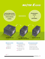
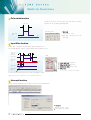
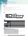
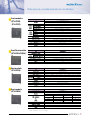
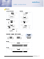
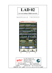
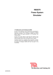
Leader in Electrics & Automation
Programmable Logic Controller
MASTER-K120S Series
Automation Equipment
BUILT-IN CNET
RUN
PAU/REM
STOP
ON
OFF
High speed counter (P000~P007)
ROM
MODE
Rom Mode
1 phase 100kpps 2Ch, 10kpps 2Ch (Total 4Ch)
2 phase 50kpps 1Ch, 20kpps 1Ch (Total 2Ch)
RS-485 (Ch No.1)
Multi-drop communication
Modbus communication
Input terminal
RS-232C (2 ports)
Loader port: 2 (Rx), 3 (Tx), 5 (SG)
Ch No.0: 4 (Rx), 7 (Tx), 5 (SG)
Extension terminal
(Extansion, RTC,
Memory modules)
Positioning function (P040~P043)
- 2 Axes (100kpps)
PID control (8 loops)
Output terminal
●Various base (main) units
CONTENTS
Features
�4
Data register for special modules
� 23
System configuration
�5
Communication interface
� 24
CPU specifications [Standard type]
�6
Extension communication modules
� 25
CPU Specifications [Economic type]
�8
Communication specifications
� 26
Digital I/O specifications (Relay)
�9
Built-in/Communication module setting switch � 26
Digital output specifications (TR output)
� 11
Network configuration
� 27
Wiring diagram
� 12
Cable connection
� 29
Built-in functions
� 14
Product list
� 30
Analog module
� 19
Dimensions
� 31
RTD module / Analog timer
� 22
Standard type
�20 points (I: 12, O: 8)
�30 points (I: 18, O: 12)
�40 points (I: 24, O: 16)
�60 points (I: 36, O: 24)
Economic type
�10 points (I: 6, O: 4)
�14 points (I: 8, O: 6)
�20 points (I: 12, O: 8)
�30 points (I: 18, O: 15)
●Processing speed
0.1㎲ / step
(Economic type: 0.4㎲ / step)
●Program capacity
10 ksteps (Economic type: 2 ksteps)
●Battery-less backup
2
Dedicated basic function
The best partner
Powerful built-in functions
in price
Various extension
&
modules
performance
Digital I/O modules: 5 types
● Digital I/O modules
G7E-DR10A (6/4)
G7E-DR20A (12/8)
Special modules: 7 types
(Analog I/O, Analog timer, Temperature)
● Special modules
G7F-ADHA (AD: 2Ch / DA: 1Ch)
※ G7F-ADHB (AD: 2Ch / DA: 2Ch)
Communication modules: 6 types
● Communication modules
G7L-CUEB: RS-232C 1Ch (Ch0)
G7L-CUEC: RS-422 1Ch (Ch0)
G7F-AD2A (AD: 4Ch)
G7L-DBEA: DeviceNet slave (Ch0)
※ G7E-DC08A (8/0)
G7F-DA2I (DA: 4Ch, Current)
G7L-PBEA: Profibus-DP slave (Ch0)
※ G7E-RY08A (0/8)
※ G7F-DA2V (DA: 4Ch, Voltage)
G7L-FUEA: Fieldbus interface (Fnet, Ch0)
G7F-AT2A (4 points, 0 ~ 200)
G7L-RUEA: Fieldbus interface (Rnet, Ch0)
G7E-TR10A (0/10)
※ G7F-RD2A (4Ch)
※: Slim type
3
Features
Main unit
�Economic type: 10/14/20/30 points (10/14 points, built-in analog timer 2 points)
- Total 70 points are available (up to 2 extension modules can be connected; only one communication module can be applied)
�Standard type: 20/30/40/60 points DR type, DRT type (DRT types have 4 transistor output points for positioning)
- Total 120 points are available (up to 3 extension modules can be connected; only one communication module can be applied)
�Easy interface with SMART I/O (Rnet, Modbus) due to the increased P area (P000~P63F)
High speed processing
�Basic commands: 0.1~0.9㎲/step
�Application command: several ㎲~several tens of ㎲/step
�Special module processing: several hundreds of ㎲~1㎳/module
※ Economic type: 0.4㎲/step (Min.)
Battery-less backup
“
�Program backup method: User program is automatically backed up in EEPROM
(EEPROM backup while online editing)
�Data backup methods: Supercapacitor (over 2000hours at normal temperature)
Powerful
built-in functions
Compact extension modules
Various input handling
�Input filter: Delay time can be set from 0㎳ to 1000㎳ (8 points unit)
�Pulse catch: 10㎲ (P0, P1), 50㎲ (P2~P7)
※ Economic type: 50㎲ (P0~P3)
�External interrupt: 10㎲ (P0, P1), 50㎲ (P2~P7)
※ Economic type: 50㎲ (P0~P3)
Improved high speed counter function
(32-bit signed counter)
�1 Phase: 100kpps 2Ch, 20kpps 2Ch (Total 4Ch)
�2 Phase: 50kpps 1Ch, 10kpps 1Ch (Total 2Ch)
�Additional functions: Ring counter, Comparison output, RPM, Latch counter, Preset function
※ Economic type � 1 phase: 20kpps (4Ch), 2 phase: 10kpps (2Ch)
Positioning function (DRT type only)
�Control axis: 2 axes (100kpps)
�Operation mode: Single, Repeated, End, Keep, Cont
�Additional functions: Return to origin, JOG operation, Speed operation, PWM output
Increased No. of communication channels and functions (Total 3 Channels)
�Supports built-in RS-232C/RS-485 (Total 2Ch)
�Supports no protocol mode and Communication monitoring for Ch0/1 (KGLWIN)
※ Economic type � K7M-DR10UE-14UE: 1 loader port and 1 RS-485 port (Total 2Ch)
� K7M-DR20UE-30UE: 1 loader port and 1 RS-232C port (Pin No.: 4 (Rx), 7 (Tx), 5 (SG))
Improved PID control function (Standard type only)
�Relay and PRC auto-tuning
�PWM output, Anti-derivative kick, Positioning/Velocity algorithm can be assigned
4
”
System configuration
System configuration
▶▶Main modules
▶▶Number of available
extension modules
● Product type
- K7M-DR(T)20U: DC input 12 points / Relay 8 points / (Relay output 4 points / TR 4 points)
- K7M-DR(T)30U: DC input1 8 points / Relay 12 points / (Relay output 8 points / TR 4 points)
- K7M-DR(T)40U: DC input 24 points / Relay 16 points / (Relay output 12 points / TR 4 points)
- K7M-DR(T)60U: DC input 36 points / Relay 24 points / (Relay output 20 points / TR 4 points)
●Digital I/O: 3 modules
●Special module: 3 modules
●Communication I/F: 1 module
●RTC module (1 module)
●Memory module (1 module)
※ Standard type: Max. 3 extension modules are connectable
※ Economic type: Max. 2 extension modules are connectable
(RTC/Memory module and be added after extension modules)
(+, - )
RS-485
(+, - )
Loader port
2 (Rx), 3 (Tx), 5 (SG)
RS-232C
4 (Rx), 7 (Tx), 5 (SG)
“
Loader (KGLWIN)
Various
extension modules
HMI
”
▶▶Extension modules
● Digital input/output modules
Input
G7E-DC08A: DC input 8 points
Output
G7E-TR10A: TR output 10 points
G7E-RY08A: Relay output 8 points
Input/output hybrid module
G7E-DR10A: DC 6 points / Relay 4 points
G7E-DR20A: DC 12 points / Relay 8 points
● Special modules
A/D
G7F-AD2A: 4Ch
D/A
G7F-DA2V: 4Ch (Voltage output)
G7F-DA2I: 4Ch (Current output)
A/D, D/A
G7F-ADHA: 2Ch/1Ch
G7F-ADHB: 2Ch/2Ch
RTD
G7F-RD2A: 4Ch
Analog timer G7F-AT2A: 4 points (0~200)
● Communication modules
G7L-CUEB: RS-232C 1Ch
G7L-CUEC: RS-422 1Ch
G7L-FUEA: Fieldbus interface (Fnet)
G7L-RUEA: Fieldbus interface (Rnet)
G7L-DBEA: DeviceNet slave
G7L-PBEA: Profibus-DP slave
● Other option modules
G7E-RTCA: RTC module
G7E-M256B: Memory module
5
CPU specifications [Standard type]
Specifications
Item
CPU operation method
I/O control method
Program language
Numbers of
Basic
instruction
Application
Processing speed
Program capacity
I/O Points
P
M
K
L
F
Memory device
T
C
S
D
Operation mode
Self-diagnostic functions
Data backup method
Max. extension stage
PID Control function
Cnet I/F Function
Capacity
Built-in
functions
High
speed
counter
Mode
Additional
function
Specifications
K7M-DR20U
K7M-DR30U
K7M-DR40U
K7M-DR60U
K7M-DRT20U
K7M-DRT30U
K7M-DRT40U
K7M-DRT60U
Cyclic execution of stored program, Time-driven interrupt, Interrupt task operation
Scan synchronized batch processing method (refresh method), Direct method by command
Ladder Diagram, Instruction List
30
277
Basic command: 0.1㎲/step
10kstep
20 points
30 points
40 points
60 points
P000~P63F
M000~M191F
K000~K31F
L000~L63F
F000~F63F
100㎳: T000~T191
10㎳: T192~T250
1㎳: T251~T255
C000~C255
S00.00~S99.99 (100×100 steps)
D0000~D4999
RUN, STOP, PAUSE
Detect errors of scan time, Memory, I/O, Power supply
Set by parameter
3 (except RTC/Memory pack)
Control by command, Auto-tuning, PWM output
Forced output, Set scan time anti-windup
Delta MV function, SV-Lamp function
MASTER-K dedicated protocol support
Modbus protocol support
RS-232C 1 port
User-defined protocol support
RS-485 1 port
No protocol support
1 Phase: 100kHz 2Ch / 20kHz 2Ch
2 Phase: 50kHz 1Ch / 10kHz 1Ch
It has 4 different counter functions
� 1 phase, up-down by program
� 1 phase, up-down by B-phase input
� 2 phase, up-down by 1 phase
� 2 phase, up-down by phase difference
� Internal/External preset function
� Latch counter function
� Comparison output function
� RPM function
※ RTC/Memory module must be connected to the last extension terminal.
6
Remark
I/O relay
Aux. relay
Keep relay
Link relay
Special relay
Timer
Counter
Step relay
Data register
Specification
Specifications
K7M-DR30U
K7M-DR40U
K7M-DRT30U
K7M-DRT40U
Item
Basic function
Built-in
functions
Sitioning
function
Positioning
Return to origin
Jog
Pulse catch
External interrupt
Input filter
Weight (g)
K7M-DR20U
K7M-DR60U
K7M-DRT20U
K7M-DRT60U
No, of axis: 2 axes
Control method: PTP/speed
Control unit: Pulse
Positioning data: 20 data per each axis (Step No: 1~20)
Operation mode: End, Keep, Cont
Control method: Single, Repeated, Operation
Positioning method: Absolute method/Incremental method
Address range: -2,147,483,648 � 2,147,483,647
Speed: Max. 100kpps (Speed: 5 � 100,000pps)
Acceleration/Deceleration processing (Operation pattern: Trapezoidal method)
Origin detection when approximate origin turns off
Origin detection after deceleration when approximate origin turns on
Speed setting range: 5 � 100,000pps (High/Low)
Pulse width: 10㎲ 2 points (P0000~P0001) / 50㎲ 6 points (P0002~P0007)
8 points: 10㎲ 2 points (P0000~P0001) / 50㎲ 6 points (P0002~P0007)
0, 1, 2, 5, 10, 20, 50, 100, 200, 500, 1000㎳ set by user
520
540
660
850
Remark
DRT Type
only
CPU Operation mode
RUN
PAU/REM
STOP
[Mode key]
Mode key position
Operation mode
RUN
STOP
STOP → PAU/REM ※
PAU/REM → RUN
RUN → PAU/REM
PAU/REM → STOP
Local RUN
Local STOP
Remote STOP
Local RUN
Local PAUSE
Local STOP
※ PLC operates continuously when changed from Remote RUN to Local RUN.
Remote RUN/Remote STOP control is available in KGLWIN.
●
●
●
●
RUN Mode (Local RUN/Remote RUN): operating mode; initialization of data area is executed when the first scan starts.
STOP Mode (Local STOP/Remote STOP): program is not operated; program transferring in KGLWIN is available only in Remote STOP mode.
PAU (PAUSE): program operation is temporarily stopped; if it returns to RUN mode, the operation will continue from the state before it stopped.
REM (Remote): changeable mode to Remote RUN/STOP in KGLWIN
7
CPU Specifications [Economic type]
Specifications
Item
CPU operation method
I/O control method
Program language
Basic
Numbers of
instruction
Application
Processing speed
Program capacity
I/O points
P
M
K
L
F
Memory device
T
C
S
D
Operation mode
Self-diagnostic function
Data backup method
Max. extension stage
Built-in analog timer
Input filter
Interrupt
Pulse catch
Built-in
function
Cnet I/F
Weight (g)
Specifications
K7M-DR10UE
K7M-DR14UE
K7M-DR20UE
K7M-DR30UE
Cyclic execution of stored program, Time-driven interrupt, Interrupt task operation
Scan synchronized batch processing method (refresh method), Direct method by command
Ladder Diagram, Instruction List
30
265
Basic command: 0.4㎲/step
2kstep
10 points
14 points
20 points
30 points
P000~P63F
M000~M191F
K000~K31F
L000~L63F
F000~F63F
100㎳: T000~T191
10㎳: T192~T250
1㎳: T251~T255
C000~C255
S00.00~S99.99 (100×100 Steps)
D0000~D4999
RUN, STOP, PAUSE
Detect errors of scan time, Memory, I/O, Power supply
Set by parameter
2 (except RTC/Memory pack)
2 points
None
0, 2, 5, 10, 20, 50, 100, 200, 500, 100㎳ set by user
4 points (P0~P3), 50㎲
4 points (P0~P3), 50㎲
Built-in RS-485
Built-in RS-232C
MASTER-K dedicated protocol (LG protocol)
Modbus protocol
User-defined protocol
No protocol support
520
540
660
850
Remark
I/O relay
Aux relay
Keep relay
Link relay
Special relay
Timer
Counter
Step relay
Data register
Specifications
Type
Digital I/O module
Cnet interface module
RTC module
Memory module
Item
G7E-DR10A
G7E-DR20A
G7E-TR10A
G7E-DC08A
G7E-RY08A
G7L-CUEB
G7L-CUEC
G7E-RTCA
G7M-M256B
※ Special function modules are available after October, 2003.
8
Specifications
DC 24V input 6 points / Relay output 4 points
DC 24V input 12 points / Relay output 8 points
TR input 10 points
DC 24V input 8 points
Relay output 8 points
RS-232C 1Ch
RS-422 1Ch
RTC module
Memory module
Remark
Digital I/O specifications (Relay)
Digital input specifications
Model
Specification
Input points
Insulation method
Rated input voltage
Rated input current
Operating voltage range
Max. simultaneous
input points
On Voltage/On current
Off Voltage/Off current
Input impedance
O f f � On
On � Off
Common terminal
Operating indicator
Response
time
Main unit
K7M-DR20U
K7M-DR30U
K7M-DR40U
K7M-DRT20U
K7M-DRT30U
K7M-DRT40U
12 points
18 points
24 points
Photocoupler
DC 24V
7㎃
DC 20.4~28.8V (ripple rate〈 5%)
Extension module
K7M-DR60U
K7M-DRT60U
36 points
G7E-DR10A
G7E-DC08A
G7E-DR20A
6 points
8 points
12 points
100% Simultaneous on
DC 19V or higher / 5.7㎃ or higher
DC 6V or lower / 1.8㎃ or lower
Approximate 3.3㏀
0, 1, 2, 5, 10, 20, 50, 100, 200, 500, 1000㎳ (default: 10㎳), Set by user
0, 1, 2, 5,1 0, 20, 50, 100, 200, 500, 1000㎳ (default: 10㎳)
12 points/COM
18 points/COM
12 points/COM
18 points/COM
LED
6 points/COM
4 points/COM 12 points/COM
Digital output specifications (Relay)
Main unit
Model
K7M-DR20U
Specification
Output points
Insulation method
Rated load voltage/current
Min. load voltage/current
Max. load voltage/current
Off leakage current
Max. on/off frequency
Surge absorber
Mechanical
Service life
Electrical
O f f � On
Response
time
On � Off
Operation indication
K7M-DR30U
Extension module
K7M-DR40U
K7M-DR60U
8
12
16
24
Relay insulation
DC 24V/2A (Register load), AC 220V/2A (COS Ψ =
Δ 1)/1point 5A/COM
DC 5V/1㎃
AC 250V, DC 110V
0.1㎃ (AC 220V, 60Hz)
1,200/hr
None
20 million times or more
Rated load voltage/current: 100,000 or more
AC 200V/1.5A, AC 240V/1A (COS Ψ =
Δ 0.7) 100,000 or more
AC 200V/1A, AC 240V/0.5A (COS Ψ =
Δ 0.35) 100,000 or more
DC 24V/1A, DC 100V/0.1A (L/R = 7㎳) 100,000 or more
10㎳ or less
12㎳ or less
LED
G7E-DR10A
G7E-RY08A
G7E-DR20A
4
8
8
9
Digital I/O specifications (Relay)
Input circuit diagram
Input No. P002~P023
Input No. P000~P001 (Basic module)
R
R
COM
Internal
circuit
R C
Internal
circuit
R
COM
Output circuit diagram
L
Internal
circuit
Relay
L
COM
Connection display of Digital input part
According to external equipment type, refer to the following connection between DC input part and external devices.
External equipment (I/Os)
Relay
output
type
NPN
Open
collector
output
type
NPN
Current
output
type
10
Input part
IN
Relay
Sensor
7mA
+
Output
0V
CON
Power
(for sensor)
IN
7mA
CON+
Uses the same power
in input power and
power for sensor
+
Constant
current
circuit
Output
0V
IN
7mA
Power
(for sensor)
CON+
External equipment (I/Os)
PNP
Current
output
type
Voltage
output
type
Input part
Uses the same power
in input power and
power for sensor
+
Power
(for sensor)
Output
0V
IN
7mA
CON-
Uses the same power
in input power and
power for sensor
+
CON+
Output
0V
IN
Power
(for sensor)
Digital output specifications (TR output)
Main module
Main module
K7M-DRT40U
12 points
4 points
Photocoupler
DC 12/24V
DC 10.2~26.4V
0.1A/point
Zener diode
0.1㎃ or less
DC 0.3V (0.1A) or less
4A, 10㎳ or less
0.2㎳ or less
0.2㎳ or less
1point/COM
LED
Model
K7M-DRT20U
4 points
4 points
Specification
Relay output points
TR output points
Insulation method
Rated load voltage
Input operation voltage range
Max. load current
Surge absorber
Off leakage current
Off voltage drop
Inrush current
Response
O f f � On
time
On � Off
Common method
Operation indication
K7M-DRT30U
8 points
4 points
Extension unit
G7E-TR10A
0 points
0 points
K7M-DRT60U
20 points
4 points
0.5A/point, 4A/COM
Clamp diode
DC 1.5A or less
2㎳ or less
2㎳ or less
10 points/COM
Circuit diagram
24V
P40, P41
Internal
circuit
Output wiring
1
8
2
7
3
6
4
5
TR1
AC110V
~240V P40 P41
P42
P
FG COM0 COM1 COM2 P43 COM3
R2
R
3
P42, P43
24V
P/C
Internal
circuit
TR1
L
R2
R
3
L
L L
DC12V/24V
�P40~P43 of K7M-DRT��U type are for positioning control TR output (These can be used as general TR output).
�TR parts would be damaged, when used for AC load.
11
Wiring diagram
I/O Part (Main module)
●K7M-DR20U
●K7M-DR30U
●K7M-DR40U
24V OUT
DC5/12/24V
AC110/220V
●K7M-DR60U
DC5/12/24V
AC110/220V
DC5/12/24V
AC110/220V
I/O Part (Extension module)
●G7E-DR10A
DC5/12/24V
AC110/220V
DC5/12/24V
AC110/220V
12
I/O Part (Extension module)
● G7E-TR10A
● G7E-DR20A
G7E-RY08A (Output)
● G7E-DC08A
G7E-TR10A
PROGRAMMABLE
LOGIC
CONTROLLER
∙
∙
∙
Q00
Q02
Q04
Q06
Q08
COM0
∙
Q04
Q05
Q06
Q07
Q08
P
00
I02
I01
IN 24VDC 7mA
L
DC12/24V
L
L
L
L
L
L
00
01
02
03
04
G7E-DC08A
PROGRAMMABLE 05
LOGIC
06
CONTROLLER
07
L
L
COM0
I03
L
I04
COM0
I06
I05
I07
DC5/12/24V
AC110/220V
※ K7M-DRxxS/DC: PLC operating power is DC 24V.
● I/O allocation method
Addressing to each module for data output.
Items
Main
Extension
#1
Extension
#2
Extension
#3
Special
Type
Input
Output
Input
Output
Input
Output
Input
Output
Area
P000~P03F
P040~P07F
P080~P08F
P090~P09F
P100~P10F
P110~P11F
P120~P12F
P130~P13F
-
Remark
64 points
64 points
16 points
16 points
16 points
16 points
16 points
16 points
A/D, A/T, Communication
Basically, I/O area is a fixed-point type. Special and communication
modules have nothing to do with I/O allocation. Rest area can be used
as internal relays.
Example)
DRT20U
(12/8)
Input
Output
P000~000B
P040~P047
+
DR10A + ADHB※ + DR20A
(12/8)
(6/4)
P080~P085
P090~P093
-
P100~010B
P110~P117
※ No allocation of I/O point
13
Built-in functions
Pulse catch function
Using pulse catch function, a very short pulse signal can be taken as valid input
signal which can’t be executed by general digital input.
Min. 10㎲
Pulse catch setting
Input image
data
● Input point:
8 points (P000 ~ P007)
● Input signal shorter than scan time can
be detected.
Time
Input filter function
An input signal is valid after the setting time after an input filter signal becomes on.
The input image data turn off after the setting time after an input filter signal becomes off.
Input on/off
delay time
(Filter time)
Setting
Input signal
Input image
data
Time
Input signal
Input image
data
●
●
●
●
Useable input point: All input points
Setting input filter time: 8-point unit
Assignment by group (Extension Input)
Setting range: 0 ~ 1s
(0, 1, 2, 5, 10, 20, 50, 100, 200, 500, 1000㎳)
Any input signal shorter than assigned on/off filter time from KGLWIN is ignored.
※ Using input filter function, malfunction by noise can be prevented effectively.
Interrupt function
MK120S can perform interrupt function using input points without any special interrupt module.
● Input point:
Max. 8 points (P000 ~ P007)
● Rising, Falling, Rising & Falling
14
High speed counter function
Using HSC function, High speed pulses which are generated from encoder of pulse generator can be counted.
● Function
Function
Description
4 counter modes are available as follows.
∙1-phase operation mode: Increment count by program
∙1-phase+direction mode: Increment/decrement count by B-phase state
∙2-phase CW/CCW mode: Increment/decrement count by input pulse
∙2-phase multiplication mode: Increment/decrement count by phase difference
Counter latch function in power off or counter disable
Change current value to preset value
When counter value reaches set value, it rotates to 0
When counter value reaches set value, turns on output contact point of executes interrupt program.
Calculates the RPM(Rotate per minute) of input pulse
Counter mode
Latch counter
Preset function
Ring counter function
Comparison output
RPM function
● Specifications
Item
Point
Input signal
Counting range
Counting speed
Additional function
Specifications
1-phase 4 points, 2-phase 2 points
A-phase, B-phase, Preset input (P4 ~ P7)
-2,147,483,648 ~ 2,147,483,647 (Binary 32 bit)
Ch0, Ch1(1-phase 100kpps / 2-phase 50kpps) Ch2, Ch3 (1-phase 20kpps / 2-phase 10kpps)
Ring counter, Preset, Comparison output, RPM
● Input
1) A/B-phase input
● Input terminal diagram
Item
Rated input voltage/current
On guaranted voltage
Off guaranted voltage
Specifications
DC 24V (7㎃)
20.4V ~ 28.8V
Below 6V
Counter input
Preset input
Common terminel
① ② ③ ④ ⑤ ⑥ ⑦ ⑧
⑨
2) Preset input
Item
Rated input voltage/current
On guaranted Voltage
Off guaranted Voltage
On delay time
Off delay time
No.
Terminal No.
①
②
③
④
⑤
⑥
⑦
⑧
⑨
P000
P001
P002
P003
P004
P005
P006
P007
COM 0
Specifications
DC 24V (7㎃)
20.4V ~ 28.8V
Below 6V
Below 200㎲
Below 200㎲
P00
P02
P01
P04
P03
P05
P06
P08
P07
Name
1 phase
Ch0 Counter input
Ch1 Counter input
Ch2 Counter input
Ch3 Counter input
Ch0 Preset 24V
Ch1 Preset 24V
Ch2 Preset 24V
Ch3 Preset 24V
P10 COM0
P0F
P11
P23 COM1
P22 24G 24V
Use
2 phase
Ch0 A-phase input
Ch0 B-phase input
Ch2 A-phase input
Ch2 B-phase input
Ch0 Preset 24V
1 phase
Counter input terminal
Counter input terminal
Counter input terminal
Counter input terminal
Preset input terminal
Ch2 Preset 24V
Preset input terminal
Input Common
Common terminal
2 phase
A-phase input terminal
B-phase input terminal
A-phase input terminal
B-phase input terminal
Preset input terminal
Preset input terminal
Preset input terminal
Preset input terminal
Common terminal
※ Refer to user’s manual regarding detail specifications.
15
Built-in functions
Positioning control
The position of servo or stepping motor can be controlled by positioning function.
● Output
Signal name
Phase
Direction
Rated load
Load
Max. loaded
voltage
voltage range
current
Pulse output
DC 12/24V DC 10.2~26.4V
(forward pulse,
Forward direction
reverse pulse)
Phase
100㎃
Max. voltage
drop during On
≤ DC 0.3V
Reverse direction
Direction
K120S Main unit
Drive
P40, P41
Motor
P42, P43
● Output terminal diagram
⑥
AC 1 00-240V P40
FG
P41
P42
Motor
P
COM0 COM1 COM2 P43 COM3
①
Motor drive
②
③ ④ Direction output
⑤
COM0~3
Phase output
No. Terminal No.
①
P040
②
P041
③
P042
④
P043
⑤
COM
Name
Positioning(Ch0)
Positioning(Ch1)
Direction pulse
(Ch0)
Direction pulse
(Ch1)
Common
⑥
P
24V
● Specifications
Item
No. of control axis
Control method
Control unit
Positioning data
Positioning method
Address range
Speed
Acceleration/
Positioning
Deceleration method
Backlash compensation
Bias speed
Speed limit
Operation mode
Operation method
Speed
High/Low
Dwell time
Origin return
1
Method
2
3
JOG
Speed
High/Low
PWM output
16
Specifications
2 axes
PTP (point-to-point), speed control
Pulse
20 data per each axis (operation step number: 1~20)
absolute/incremental method
-2,147,483,648~2,147,483,647
Max. 100kpps, Speed range in setting: 5~100,000pps (unit of pulse)
Operation pattern: Trapezoidal method
Acceleration/deceleration time: 0~10.000ms (unit of 1ms)
0~1,000pulses
5~100,000pps
5~100,000pps
End, Keep, Continuous operation
Single, Repeat operation
Speed setting range: 5~100,000pps
Setting range: 0~10,000㎳
Origin detection when approximate origin turns off
Origin detection after deceleration when approximate origin turns on
Origin detection by approximate origin
Speed setting range: 5~100,000pps
Period setting range: 1~20,000㎳
Duty setting range: 0~100%
Usage
Pulse output terminal
Pulse output terminal
Direction
output terminal
Direction
output terminal
Common terminal
External 24V
supply terminal
Positioning control - wiring
● Wiring with DC5V
Max. 2m
K7M-DRT ** U
Signal
Pulse
Ch1
P40
P41
CWCW+
CCWCCW+
COMO COM1
Common
P42
Direction
P43
COM2 COM2
Common
* Note 3)
* Note 4)
Stepping motor driver
Ch0
DC5V
+24V Input
P
P
Origin point
P04
P06
TIMING
Approximiate origin point
P05
P07
COM
Lowear limit�
P00
P02
Upper limit
P01
P03
Input point
Emergency stop
COMO (input)
Common
* Note 1)
DC24V
● Wiring with DC24V
Max. 2m
K7M-DRT ** U
Signal
Pulse
Common
Direction
Common
* Note 3)
* Note 4)
Stepping motor driver
Ch0
Ch1
P40
P41
2K, 1/2W
COMO COM1
P42
P43
COM2 COM2
DC24V
2K, 1/2W
* Note 2)
CWCW+
CCWCCW+
+24V Input
P
P
Origin point
P04
P06
TIMING
Approximiate origin point
P05
P07
COM
Lowear limit�
P00
P02
Upper limit
P01
Emergency stop
Common
* Note 1)
P03
Input point
DC24V
COMO (input)
※ Note) 1. In case of VEXTA RK series, TIMING output turns on when a motor rotates at every 7.2 degree. For exact‘return to origin’
, we suggest you to configure
‘AND’operation using TIMING output and the DOG sensor. It may be different to each system features to return to origin by the DOG sensor without
TIMING output signal (The rated input for the origin of K120S is DC24V.)
2. Using DC24V, wire a proper resistor to driver in series.
3. Input points for origin point, approximate origin point, and upper/lower limit signal are fixed but if they’re not used, you are able to use them as general
input points. You can use emergency stop with the command (POSCTR).
4. Positioning phase of K120S is as follows: Set the input mode of a step motor driver to 1 phase input mode because motor operation is determined by
rotating direction input.
Pulse input
On
Off
Rotating
direction input
On
Off
cw
ccw
cw
Motor operation
ccw
※ The maximum connection cable between PLC
and driver equipment is 2m. Please refer to
user’s manual for the connection with other
servo drivers.
17
Built-in functions
PID Control
● Features
�PID function is integrated into the main unit. And, all the PID functions can be performed with instruction (PID8, PID8AT).
�P operation, PI operation and on/off operation can be selected easily.
�Manual output (user-defined forced output) is available.
�By proper parameter setting, it can keep stable operation regardless of external disturbance.
�The operation scan time (the interval that PID controller gets sampling data from an actuator) is changeable for optimizing the system characteristics.
�PWM (pulse width modulation) output is available
※ P, I, and D value are automatically calculated by auto-tuning.
● System
Manual MV
Set value
Present
value
SV
PID calculation
PV
MV
Manipulation
value
Automated
MV
D/A
converting module
A/D
converting module
Control
object
Sensor
● Specifications
Item
No. of PID loop
Proportional value
PID
Integral value
Differential value
Setting value
Present value
Manipulation value
Manual operation value
Control action
Scan time
Processing type
Specifications
8 loops
1~10,000 (100-time scaled up), D area
1~20,000 (100-time scaled up), D area
1~20,000 (100-time scaled up), D area
0~4,000, D area
0~4,000, D area
0~4,000, D area
0~4,000, D area
P, PI, PID, P_PWM, PI_PWM, PID_PWM, On-Off
1~100 (0.1 second unit), D area
Velocity type, Position type
● Example
P, I and D values calculated
� Auto-tuning: automatically
� PID operation
18
Analog module
Specification
Specifications
A/D∙D/A Hybrid module
Item
G7F-ADHA
Voltage
Input range
A/D Module
G7F-ADHB
G7F-AD2A
D/A Module
G7F-DA2I
G7F-DA2V
DC 0�10V (input resistance: more than 1㏁)
DC 0�20㎃ (input resistance 250Ϊ)
Current
DC 4�20㎃ (input resistance 250Ϊ)
Classified by parameter
Digital output
Analog
input
12 bits (0~4,000)
Set by jumper pin for
V/I selection upper
part of product
(Up: V, Down: I)
Voltage/current
selection
Set by dip S/W for
V/I selection on left
side of product
(left: V, Right: I)
Set by input terminal
(When current input is
used, short the V and I
terminal)
-
V/I selected by KGLWIN parameter
Short the V and I terminal when current input is used.
No. of channel
Absolute
max. Input
2Ch/module
4Ch/module
V
DC +12V
DC ±15V
I
DC +24㎃
DC +25㎃
V
DC 0�10V (External load resistance 2㏀�1㏁)
DC 0�20㎃ (load
resistance 510Ϊ)
DC 4�20㎃ (load
resistance 510Ϊ)
DC 0�20㎃ (External load resistance 510Ϊ)
Output range
I
DC 4�20㎃ (External load resistance 510Ϊ)
Classified by parameter
DC 0�10V
(load resistance
2㏀�1㏁)
Analog
output
Digital input
12 bits (0~4,000)
Voltage/current selection
Separated from terminal
No. of channel
Absolute
max. output
1Ch/module
2Ch/module
V
DC +12V
I
DC +24㎃
V
Max. resolution
I
Insulation
DC 0�10V: 2.5㎷ (1/4000)
DC 0�20㎃: 5㎂
DC 0�20㎃: 5㎂ (1/4000)
(1/4000)
DC +12V
2.5㎷ (1/4000)
DC 4�20㎃: 6.25㎂
(1/3200)
0.5%
1㎳/Ch+scan time
500㎳/Ch+scan time
1㎳/Ch+scan time
Photocoupler insulation between I/O terminal and PLC power supply (Non-insulation between channels).
Connect terminal
Internal current consumption
Weight
DC +24㎃
±0.5% (full scale)
Max. conversion speed
External power
supply
4Ch/module
DC 4�20㎃: 6.25㎂ (1/3200)
Accuracy
Common
12 bits (0~4,000)
9 points 2 terminals
8 points 2 terminals
2 points/16 points terminals
16 points terminal
8 points 2 terminals
20㎃
20㎃
100㎃
20㎃
15㎃
80㎃
95㎃
100㎃
80㎃
90㎃
240g
180g
300g
280g
160g
V
I
DC 21.6�26.4V
※ Caution for wiring
- 2-core, shielded twisted pair cable is recommended.
Size: AWG22 (0.3㎟) or higher.
- Wiring with high voltage or generation line, it makes induction failure which may cause malfunction or be out of order.
19
Analog module
Names of parts and functions
G7F-ADHA
⑤
①
G7F-ADHB
④
④
①
24V
ChO
Ch1
V+
Input
G7F- ADHA
PROGRAMM EABL
LOGIC
CONTROLLER
⑥
Input
select
ChO Ch1
①
V0+ I0 + V1+ I1 +
V0- I0 - V1- I1 Ch0
Ch1
I-
Output
⑦
PWR
PWR
Input
Ch1 Input
Ch0
24V V0 Com0 I1
24G I0
V1 Com 1
⑤
②
Name
PWR LED
③
②
G7F-ADHA/G7F-ADHB
Indicate the operating status.
When current input is used,
Short the V and I terminal.
②
⑦
G7F-ADHB
PROGRAMMABLE
LOGIC
CONTROLLER
⑥
Ch0 (Input)
Ch1 (Input)
V0
I 0 Com0 V 1
I 1 Com1
③
No.
VI+
Output
Voltage
input
Current
input
Ch0 ( Input )
V0 I0 COM0
Ch0 ( Input )
V0 I0 COM0
Analog input terminal
Connect upper parts by jumper pins.
Jumper pin of analog input (V/I)
Input
select
Voltage input
Current input
Ch0 Ch1
③
Jumper pin of analog input
Connect upper parts
by jumper pins
Right: Ch1
Left: Ch0
S/W to choose voltage or current.
Input select
Ch0
③、
Connect lower parts
by jumper pins
Ch1
Dip switch of analog input
Right: Current
Left: Voltage
Terminal to output analog signal.
④
Voltage output
Current output
Analog Output terminal
V+ V- I+
Output
I-
V+ V- I+
Output
G7F-ADHB has 2 output channels so it can select voltage/current respectively.
20
⑤
External power input terminal
External voltage 24VDC needs to this terminal.
⑥
Extension cable
The cable is used to connect while an analog mixture module is used.
⑦
Extension cable connector
The connector connects extension cable when an extension module is used.
I-
Names of parts and functions
G7F-AD2A
④
G7F-DA2I
G7F-DA2V
④
③
①
①
24V 24G
24V 24G
Input
Input
G7F- AD2A
PR OG RAMM EABL
LOGIC
CONTROLLER
⑤
Input
select
Ch3
Ch2
Ch1
Ch0
⑤
⑥
⑤
PWR
Ch0
Ch1
Ch2
Ch3
V0 COM0 V1 Com1 V2 Com2 V3 Com3
I0 · I1 · I2 · I3
24V
24V
I-
24G
I-
I-
I-
V0+ V1+ V2+ V3+
V0- V1- V2- V3-
·
②
②
Name
G7F-AD2A
PWR LED
⑥
G7F-DA2V
PROGRAMMABLE
LOGIC
CO NTRO LLER
PWR
Ch0 Ch1 Ch2 Ch3
I+ I+ I+ I+
②
No.
①
⑥
G7F-DA2I
PROGRAMM EABL
LOGIC
CONTROLLER
PWR
③
①
G7F-DA2I/G7F-DA2V
Indicate the operating status.
Analog input terminal.
Voltage
input
②
Analog input terminal
Current
input
Ch0
V0 Com0
·
I0
Ch0
V0 Com0
·
I0
∙When current input is used, short the V and I terminal
Jumper pin of analog input (V/I).
Voltage input
Input
select
③
Ch 3
Ch 2
Ch 1
ChO
Jumper pin of analog input
V
Current input
Ch 3
Ch 2
Ch 1
ChO
I
Connect left parts by
jumper pin
④
External power input terminal
⑤
Extension cable
⑥
Extension cable connector
Ch 3
Ch 2
Ch 1
ChO
Connect right parts
by jumper pin
External voltage 24VDC needs to this terminal.
The cable is used to connect while an analog mixture module is used.
The connector connects extension cable when an extension module is used.
21
RTD module / Analog timer
Specifications (G7F-RD2A)
Item
Connectable RTD
Temperature input range
Digital output
Burnout detection
Accuracy
Maximum conversion speed
Number of temperature
input device points
Insulation method
Connection terminal block
Internal current consumption
V
External power supply
I
Weight
Specifications
∙Pt100 (JIS C1640-1989, DIN 43760-1980) ∙JPt100 (KS C1603-1991, JIS C1604-1981)
∙Pt100: -200~600℃ (18.48 to 313.59Ω) ∙JPt100: -200~600℃ (17.14 to 317.28Ω)
∙Digital conversion value: 0~4,000
∙Detected temperature value: -2000~6000 (10-time scaled up value)
Each of three wires at every channel has detection function
±0.5% (Full scale)
40scan/module
4 channels/module
Photocoupler insulation between the input terminal and PLC power supply (Non-insulation between channels)
Two 8-point terminal blocks
25㎃
DC 21.6�26.4V
70㎃
240g
Names of parts and functions
G7F-RD2A
③
②
②
b
B
24V A
24G B
A
b
Input
④
Ch2
Ch0
Ch0
Ch1
Ch2
Ch3
⑤
④
G7F- AT2A
PROGRAMMABLE
LOGIC
CONTROLLER
⑤
PWR
Ch1
b
B
①
Ch3
G7F-RD2A
PROGRAMMABLE
LOGIC
CONTROLLER
PWR
A
G7F-AT2A
b
A
B
·
·
①
②
Specifications (G7F-AT2A)
No.
①
Name
RUN LED
②
Timer volume
② 、 RTD input terminal
③
External power input
④
Extension cable
Extension cable
connector
⑤
22
G7F-AT2A
Timer setting per channel by
adjustment of variable resister
G7F-RD2A
Indicate the operation status
-
Terminal block which connects
Pt100Ω or JPt 100 100Ω
External voltage 24VDC
needs to this terminal
This cable is used to connect while an extension module is used
This connector connects the extension cable when an extension
module is used.
Item
Channels
Output value range
Setting type
-
Accuracy of timer
Internal current
consumption
Weight
Specification
4
8 bits (0 � 200)
Setting by variable
resistance
±2.0%
(Accuracy about max. value)
50㎃
200g
Data register for special modules
Data register for special extension modules.
Data register
D4980
D4981
D4982
D4983
D4984
D4985
D4986
D4987
D4988
D4989
D4990
D4991
Hybrid module
Extension
position
G7F-ADHA
G7F-ADHB
A/D module
D/A module
G7F-AD2A
Ch0 A/D
Ch0 A/D
Ch0 A/D
Conversion value Conversion value Conversion value
Ch1 A/D
Ch1 A/D
Ch1 A/D
Special Module Conversion value Conversion value Conversion value
#1
Ch0 D/A
Ch0 D/A
Ch2 A/D
Conversion value Conversion value Conversion value
Ch1 D/A
Ch3 A/D
Conversion value Conversion value
Ch0 A/D
Ch0 A/D
Ch0 A/D
Conversion value Conversion value Conversion value
Ch1 A/D
Ch1 A/D
Ch1 A/D
Special Module Conversion value Conversion value Conversion value
#2
Ch0 D/A
Ch0 D/A
Ch2 A/D
Conversion value Conversion value Conversion value
Ch1 D/A
Ch3 A/D
Conversion value Conversion value
Ch0 A/D
Ch0 A/D
Ch0 A/D
Conversion value Conversion value Conversion value
Ch1 A/D
Ch1 A/D
Ch1 A/D
Special Module Conversion value Conversion value Conversion value
#3
Ch0 D/A
Ch0 D/A
Ch2 A/D
Conversion value Conversion value Conversion value
Ch1 D/A
Ch3 A/D
Conversion value Conversion value
Analog
timer
RTD
input module
G7F-DA2I
G7F-DA2V
G7F-AT2A
G7F-RD2A
Ch0 D/A
Conversion value
Ch1 D/A
Conversion value
Ch2 D/A
Conversion value
Ch3 D/A
Conversion value
Ch0 D/A
Conversion value
Ch1 D/A
Conversion value
Ch2 D/A
Conversion value
Ch3 D/A
Conversion value
Ch0 D/A
Conversion value
Ch1 D/A
Conversion value
Ch2 D/A
Conversion value
Ch3 D/A
Conversion value
Ch0 D/A
Conversion value
Ch1 D/A
Conversion value
Ch2 D/A
Conversion value
Ch3 D/A
Conversion value
Ch0 D/A
Conversion value
Ch1 D/A
Conversion value
Ch2 D/A
Conversion value
Ch3 D/A
Conversion value
Ch0 D/A
Conversion value
Ch1 D/A
Conversion value
Ch2 D/A
Conversion value
Ch3 D/A
Conversion value
Ch0 A/T
Conversion value
Ch1 A/T
Conversion value
Ch2 A/T
Conversion value
Ch3 A/T
Conversion value
Ch0 A/T
Conversion value
Ch1 A/T
Conversion value
Ch2 A/T
Conversion value
Ch3 A/T
Conversion value
Ch0 A/T
Conversion value
Ch1 A/T
Conversion value
Ch2 A/T
Conversion value
Ch3 A/T
Conversion value
Ch0
Temp value
Ch1
Temp value
Ch2
Temp value
Ch3
Temp value
Ch0
Temp value
Ch1
Temp value
Ch2
Temp value
Ch3
Temp value
Ch0
Temp value
Ch1
Temp value
Ch2
Temp value
Ch3
Temp value
In RTD module, following data register are allocated.
Extension position
Special module #1
Special module #2
Special module #3
Ch0
D4980
D4984
D4988
Temp. value
Ch1
Ch2
D4981
D4982
D4985
D4986
D4989
D4990
Ch3
D4983
D4987
D4991
Ch0
D4780
D4784
D4788
Digital conversion
Ch1
Ch2
D4781
D4782
D4785
D4786
D4789
D4790
● Various ranges of input/output
Channels
Module
4Ch
G7F-DA2V
4Ch
G7F-DA2I
G7F-AD2A
G7F-ADHA
� Offset/Gain value is fixed and unchangeable.
� Analog input is set up to current initially.
� Max. 3 modules are extendible.
G7F-ADHB
G7F-RD2A
4Ch
Input: 2Ch
Output: 1Ch
Input: 2Ch
Output: 2Ch
4Ch
Ch3
D4783
D4787
D4791
Range of Input/output
DC 0~10V
DC 4~20㎃, DC 0~20㎃
DC 0~10V,
DC 4~20㎃, DC 0~20㎃
DC 0~10V,
DC 4~20㎃, DC 0~20㎃
DC 0~10V,
DC 4~20㎃, DC 0~20㎃
Pt100, JPt100
23
Communication interface
Provides three communication channels
: Built-in three communication channels
① Loader port: Pin No. 2 (Rx), 3 (Tx), 5 (SG)
② RS-232C port: Pin No. 4 (Rx), 7 (Tx), 5 (SG)
③ +, -: RS-485 port
Provides various functions
: Various and easy communication interface with dedicated mode, Modbus, User-defined mode, No protocol mode
Built-in communication
function
RV
SV
Communication device
(Measuring device etc.)
(+, -)
RS-485 (Ch No.1)
Used in multi-drop communication
External communication
function via extension module
RS-422/485 (Ch No.0)
Used in multi-drop
communication
Pin No. 2, 3, 5
(Loader port)
RS-232C (Ch No.0)
Used in modem access
Access for KGLWIN, HMI etc.
Pin No. 4, 5, 7
Communication devices
(PC, HMI etc.)
RS-232C (Ch No.0)
This is used in case of not using
extension communication modules.
* Rnet is a dedicated protocol for LGIS SMART I/Os.
24
Fieldbus interface
(Ch No.0)
- Fnet
- Rnet *
- Profibus-DP slave
- DeviceNet slave
Extension communication modules
Cnet modules
(G7L-CUEB,
G7L-CUEC)
Item
Interface
Dedicated mode
CommuniKGLWIN mode ※
cation
Modbus mode
mode
User-defined mode
Data bit
Stop bit
Data
structure Start bit
Parity bit
Synchronization
Transmission speed
Setting method
Distance
Max. number of stations
Weight
Specifications
G7L-CUEB: RS-232C (Modem)
G7L-CUEC: RS-422/485
Supports 1-to-1, 1-to-N and high-speed link
Supports remote programming and mounting via KGLWIN
Supports master and slave function with Modbus protocol (ASCII, RTU)
Supports user-defined communication
7 or 8
1 or 2
1 or 2
EVEN/ODD/NONE
Asynchronous method
1,200 / 2,400 / 4,800 / 9,600 / 19,200 / 38,400 / 57,600bps
Communication parameter setting in KGLWIN
Max. 15m (CUEB), Max. 500m (CUEC)
Max. 32 stations
180g
※ A dial-up modem is not available in KGLWIN mode.
Fnet/Rnet module
(G7L-FUEA/RUEA) ※
Specifications
1Mbps
Max. 750m
Max. 5.25km
Max. 64 stations
Communication parameter setting in KGLWIN
Shielded twisted pair cable
220g
Item
Transmission speed
Segment
Communication
Repeater (up to 6)
Max. number of stations
Setting method
Cable
Weight
※ Rnet is a dedicated protocol for LGIS SMART I/Os.
Pnet module
(G7L-PBEA)
Dnet module
(G7L-DBEA)
Item
Network type
Protocol
Media access
Transmission and speed
Network
Max. Node
Segment
Interface
Setting method
Cable
Weight
Item
Network structure
Protocol
Max. extension
&
speed
Channel
Diagnosis function
Setting method
Cable
Specifications
Profibus-DP (Slave)
EN50170/DIN19245
Token passing & Poll
1200m (9.6~187kbps) / 400m (500kbps) / 200m (1.5Mbps) / 100m (3~12Mbps)
127 stations
32 stations
RS-485 (electric)
Communication parameter setting in KGLWIN
Shielded twisted pair cable
210g
Specifications
Trunk/drop line
Peer explicit message, Predefined explicit message
Predefined I/O message (poll, bit strobe, COS, cyclic)
Speed
Network distance
Drop cable
Total drop cable
500kbps
100m or less
6m or less
39m or less
250kbps
250m or less
6m or less
78m or less
125kbps
500m or less
6m or less
156m or less
64 stations
CRC error check/Scan list
Communication parameter setting in KGLWIN
5 lines (signal 2 lines, power 2 lines, shield 1 line)
※ Only 1 communication module is available and the built-in Cnet is not available with it.
RS-485 communication (Ch No.1) is available.
25
Communication specifications
Specifications
Item
Specifications
It is LGIS dedicated protocol for easy communication with LG products.
(Supports high-speed link)
It supports Modbus, Modicon PLC’s communication protocol.
(It supports ASCII mode and RTU mode)
Dedicated
Modbus
Built-in
(Ch0,
Ch1)
User- defined
User-defined protocol allows users to communicate with other devices.
No protocol communication is useful when communication between
K120S and other devices which do not have protocol
(It communicates with other devices by frames which are set by total size of communication
bytes or user-defined code).
RS-232C: Communication using a modem
RS-422/485: Support all the built-in functions
No protocol
Cnet
Communi
-cation
module
(Ch0)
Remarks
Fnet
LGIS dedicated network between LGIS PLCs for high speed link
Rnet
LGIS dedicated network with SMART I/Os
Dnet
DeviceNet interface (slave)
Pnet
Profibus-DP interface (slave)
※ Please refer to
K120S user’s
manual regarding
LG protocol.
In case of using the
built-in
communication Ch
No.0 (4, 5, 7),
a communication
module is not
available and
vice versa.
- KGLWIN connection
- HMI connection
Loader
port
Built-in/Communication module setting switch
Built-in Cnet
Structure
Terminal block cover
Bult-in Cnet
ON
OFF
Dip switch
Built-in/Communication module
setting switch
Switch
ROM Mode
PW RO
RU NO
ER RO
ON
OFF
Contents
Set for using built-in RS-232C
(Using pin No. 4. 7. 5 of
loader port)
ROM Mode
Built-in/Communication module
setting switch
Switch
ON
OFF
Can’t use the built-in RS-232C
(Set for communication module)
ROM Mode
※ ROM mode function
ROM mode on: when power on, the program saved in the flash memory
operates
ROM mode off: when power on, it starts to drive a program saved in RAM
26
※ Ch0: No. 4, 5, 7 of 9 Pin (communication module is not available in
case of using the built-in Ch0 of Cnet)
Ch1: RS-485 (communication module available simultaneously)
Network configuration
Remote communication using a modem
● Extension communication module (G7L-CUEB)
G7L-CUEB
G7L-CUEB
Remote 1: 1 communication
Modem
Modem
※ External Module (G7L-CUEB) is needed on remote communication
by modem (built-in function is not connectable with a modem).
※ Dedicated mode and user-defined mode are available.
Multi-drop communication (2 Ways)
● Built-in function / Communication module (G7L-CUEC)
External RS-422/485 (Max. 32Ch)
G7L-CUEC
G7L-CUEC
Built-in
function
※ Multi-drop communication is available using built-in function or communication module (G7L-CUEC).
※ Both are available by simple and easy setting on Ch0/Ch1 (communication parameter in KGLWIN).
RS-485 (Max. 32Ch)
Networking is available by DeveiceNet / Profibus-DP slave
Fnet (Max. 64Ch)
G7L-FUEA
LG PLC
※ Set up‘Master’in Fieldbus of Ch0 (communication parameter in KGLWIN).
※ Communication is available by parameter setting without programming.
DeviceNet / Profibus-DP slave
LG PLC or other PLC
G7L-DBEA (PBEA)
※ Set up‘Slave’in Fieldbus of Ch0 (Communication parameter in KGLWIN).
※ Communication is available by parameter setting without programming.
27
Network configuration
1,024 points control is available in networking with SMART I/O
G7L-RUEA
+, RS-485
SMART I/O
(Rnet)
SMART I/O
<Modbus>
※ Set master in Modbus of Ch0 (communication parameter in KGLWIN)
※ Easy programming is available using‘Modcom’command.
Max. 64Ch
Rnet
RS-485 (Modbus)
<Rnet>
※ Set up‘Master’in Fieldbus of Ch0
(communication parameter in KGLWIN).
※ Easy communication is available by parameter setting without
programming.
Rnet
Remote connection in KGLWIN
: Remote connection in KGLWIN is available in both built-in communication and communication module (dedicated protocol).
KGLWIN’s connectable to any channel in network (program unload/download/monitoring are usable).
You can connect to any channel using KGLWIN (program upload/download/monitor, etc).
Master 0Ch
Slave
1Ch
Loader port
Master 0Ch
TM/TC switch: ON
TM/TC switch: ON
원거리1:1:11 communication
통신
Remote
Cable modem
Slave 1Ch
Cable modem
Built-in RS-485
Slave 31Ch
Max. 32Ch
※ Remote network by modem is available through G7L-CUEB (TM/TC switch‘ON’).
※ In method of connection select dial-up or cable modem and then choose baud rate and phone nomber. (in case of a dial-up modem).
28
Cable connection
Diagram
● Loader cable (Download cable)
● Cnet (Built-in)
Download
Program
KGLWIN (PC)
PLC (K120S)
1) K120S (9pin, CPU)
2
2
3
3
5
5
Upload
9Pin (Male)
2 (Rx)
9Pin (Female)
2 (Rx)
3 (Tx)
3 (Tx)
5 (SG)
5 (SG)
2) K120S
4 (Rx)
K120S
4 (Rx)
7 (Tx)
7 (Tx)
5 (SG)
5 (SG)
● Cnet (External)
1) G7L-CUEC
RXA
RXB
TXA
TXB
2) G7L-CUEB
1 7 8
4
6
Others
+ (485+)
- (485 - )
2
3
3
5
5
RS485(+)
RS485(- )
4) Modbus protocol
K120S (CPU)
4
5
7
3) Modbus protocol
K120S (G7L-CUEB)
2
2
5
3
3
1, 5
● Modbus (RS-232)
Others (K120S, ...)
RS485(+)
RS485(- )
Quntum (9pin)
4
6
3
7
1, 5
8
2
Quntum (9pin)
4
6
7
8
SMART I/O (9pin, Male)
Modbus (RS-485)
SDA
SDB
RDA
RDB
3) K120S
Others
2
PC (HMI)
Modbus SMART I/O #1, #2 (9pin, Male)
4
3
9
8
4
3
9
8
4
3
9
8
9pin connecter
(Top view)
5 4 3 2 1
9 8 7 6
● Rnet Cable
Rnet MASTER module (9pin, Female)
#0Ch
6
7
Rnet SMART I/O #1, #2 (9pin, Male)
#1Ch
8
9
#2Ch
8
9
● Pnet Cable
Pnet MASTER module (9pin, Female)
#0Ch
3 (A)
8 (B)
Pnet SMART I/O #1, #2 (9pin, Male)
#1Ch
3
8
#2Ch
3
8
29
Product list
K120S
Type
Item
Economic
Basic
Standard
Input
/
output
Special
Extension
K7M-DR10UE
AC 110/220V, DC 24V Input 6 points/Relay output 4 points
K7M-DR14UE
AC 110/220V, DC 24V Input 8 points/Relay output 6 points
K7M-DR20UE
AC 110/220V, DC 24V Input 12 points/Relay output 8 points
K7M-DR30UE
AC 110/220V, DC 24V Input 18 points/Relay output 12 points
K7M-DR20U
AC 110/220V, DC 24V Input 12 points/Relay output 8 points
K7M-DR30U
AC 110/220V, DC 24V Input 18 points/Relay output 12 points
K7M-DR40U
AC 110/220V, DC 24V Input 24 points/Relay output 16 points
K7M-DR60U
AC 110/220V, DC 24V Input 36 points/Relay output 24 points
K7M-DRT20U
AC 110/220V, DC 24V Input 12 points/Relay output 4 points/TR output 4 points
K7M-DRT30U
AC 110/220V, DC 24V Input 18 points/Relay output 8 points/TR output 4 points
K7M-DRT40U
AC 110/220V, DC 24V Input 24 points/Relay output 12 points/TR output 4 points
K7M-DRT60U
AC 110/220V, DC 24V Input 36 points/Relay output 20 points/TR output 4 points
K7M-DT20U ※
AC 110/220V, DC 24V Input 12 points/TR output 8 points
K7M-DT30U ※
AC 110/220V, DC 24V Input 18 points/TR output 12 points
K7M-DT40U ※
AC 110/220V, DC 24V Input 24 points/TR output 16 points
K7M-DT60U ※
AC 110/220V, DC 24V Input 36 points/TR output 24 points
G7E-DR10A
DC 24V Input 6 points/Relay input 4 points
G7E-DR20A
DC 24V Input 12 points/Relay input 8 points
G7E-TR10A
TR output 10 points
G7E-DC08A ※
DC 24V Input 8 points
G7E-RY08A ※
Relay input 8 points
G7E-DR08A ※
DC 24V input 4 points/Relay output 4 points
G7F-ADHA
A/D: 2Ch D/A: 1Ch
G7F-ADHB
A/D: 2Ch D/A: 1Ch
G7F-AD2A
A/D: 4Ch
G7F-AD2B ※
A/D: 4Ch
G7F-DA2I
D/A: 4Ch (Current output)
G7F-DA2IA ※
D/A: 4Ch (Current output)
G7F-DA2V
D/A: 4Ch (Voltage output)
G7F-AT2A
4 points (0~200)
G7F-RD2A
4Ch
G7L-CUEB
RS-232C 1Ch
G7L-CUEC
RS-422C 1Ch
Communi-
G7L-DBEA
DeviceNet slave interface module
cation
G7L-PBEA
Profibus-DP slave interface module
G7L-FUEA
Fieldbus interface module (Fnet)
G7L-RUEA
Fieldbus interface module (Rnet)
RTC
G7E-RTCA
RTC module
Memory
G7M-M256B
Memory module (256K)
※ Due on the market soon.
30
Specifications
Remarks
Position
control
Slim type
Slim type
Slim type
Slim type
Slim type
Program back-up
Dimensions
Main unit
Unit
10/14 points
20/30 points
40 points
60 points
A
85
135
165
215
B
95
145
175
225
Extension unit
Standard
Slim
31
Leader in Electrics & Automation
� For your safety, please read user's manual thoroughly before operating.
� Contact the nearest authorized service facility for examination, repair, or adjustment.
� Please contact qualified service technician when you need maintenance.
Do not disassemble or repair by yourself!
Safety Instructions
� Any maintenance and inspection shall be performed by the personnel having expertise concerned.
www.lsis.biz
� HEAD OFFICE
Yonsei Jaedan Severance Bldg., 84-11, Namdaemunno 5ga,
Jung-gu, Seoul, 100-753, Korea
Tel. (82-2)2034-4870
Fax. (82-2)2034-4713
� Global Network
�LS Industrial Systems (Middle East) FZE �
�Dubai, U.A.E.
Address: P.O.Box-114216, API World Tower, 303B, Sheikhe Zayed Road, Dubai, U.A.E.
Tel: 971-4-332-8289 Fax: 971-4-332-9444 e-mail: [email protected]
�Dalian LS Industrial Systems Co., Ltd. �
�Dalian, China
Address: No.15, Liaohexi 3-Road, Economic and Technical Development zone, Dalian 116600, China
Tel: 86-411-8273-7777 Fax: 86-411-8730-7560 e-mail: [email protected]
�LS Industrial Systems (Wuxi) Co., Ltd. �
�Wuxi, china
Address: 102-A , National High & New Tech Industrial Development Area, Wuxi, Jiangsu,214028, P.R.China
Tel: 86-510-8534-6666 Fax: 86-510-522-4078 e-mail: [email protected]
�LS-VINA Industrial Systems Co., Ltd. �
�Hanoi, Vietnam
Address: Nguyen Khe - Dong Anh - Ha Noi - Viet Nam
Tel: 84-4-882-0222 Fax: 84-4-882-0220 e-mail: [email protected]
�LS Industrial Systems Tokyo Office �
�Tokyo, Japan
Address: 16FL, Higashi-Kan, Akasaka Twin Tower 17-22, 2-chome, Akasaka, Minato-ku Tokyo 107-8470, Japan
Tel: 81-3-3582-9128 Fax: 81-3-3582-2667 e-mail: [email protected]
�LS Industrial Systems Shanghai Office �
�Shanghai, China
Address: Room E-G, 12th Floor Huamin Empire Plaza, No.726, West Yan'an Road Shanghai 200050, P.R. China
Tel: 86-21-5237-9977 (609) Fax: 89-21-5237-7191 e-mail: [email protected]
�LS Industrial Systems Beijing Office �
�Beijing, China
Address: B-Tower 17FL.Beijing Global Trade Center B/D. No.36, BeiSanHuanDong-Lu, DongCheng-District,
Beijing 100013, P.R. China
Tel: 86-10-5825-6025,7 Fax: 86-10-5825-6026 e-mail: [email protected]
�LS Industrial Systems Guangzhou Office �
�Guangzhou, China
Address: Room 1403,14F,New Poly Tower,2 Zhongshan Liu Road,Guangzhou, P.R. China
Tel: 86-20-8326-6764 Fax: 86-20-8326-6287 e-mail: [email protected]
�LS Industrial Systems Chengdu Office �
�Chengdu, China
Address: 12Floor, Guodong Buiding, No52 Jindun Road Chengdu, 610041, P.R. China
Tel: 86-28-8612-9151 Fax: 86-28-8612-9236 e-mail: [email protected]
�LS Industrial Systems Qingdao Office �
�Qingdao, China
Specifications in this catalog are subject to change without notice due to
continuous product development and improvement.
2007. 02
Address: 7B40,Haixin Guangchang Shenye Building B, No.9, Shandong Road Qingdao 26600, P.R. China
Tel: 86-532-8501-6568 Fax: 86-532-583-3793 e-mail: [email protected]
MASTER-K 120S(E) 2003. 08/(03) 2007. 02 Printed in Korea STAFF