1
USOO5802545A
United States Patent [191
[11] Patent Number:
[45] Date of Patent:
Coverdill
[54]
METHOD AND SYSTEM FOR RECORDING
VEHICLE DATA RELATIVE To VEHICLE
5,600,558
5,650,930
STANDARD TIME
2/1991 Mearek et 41. ..... ..
364/424.04
1/1991 Hagenbuch ...................... .. 364/424.04
OTHER PUBLICATIONS
['75] Inventor: Cary N. Coverdill, Boring, Oreg.
Owner’s Manual Caterpillar Driver Information Display,
Caterpillar, Feb., 1995.
ProDriverTM User Manual, Detroit Diesel Corporation, Man,
1994.
CELECI‘ RoadRelay'm User‘s Guide, Cummins Cadec, No
Dam
Primary Examiner—Vincent N. Trans
Attorney Agent, or Finn-I?m'quist Sparkman Campbell
Leigh & whinston LLP
[73] Assignee: Freightliner Corporation, Portland,
Oreg.
[21] Appl. No.: 652,776
[22] Fikd;
May 23, 1996
[51] Int. Cl.6
[52] US. Cl.
[581 Field of Search
G06F 17/00
711/35
364/550, 551.01;
[57]
340/453; 711/35’ 29
[56]
5,802,545
Sep. 1, 1998
ABSTRACT
A master clock on a truck maintains vehicle standard time
for the purposes of monitoring and recording vehicle per
formance data throughout the vehicle. Vehicle performance
Refemnces Cimd
U_S_ PATENT DOCUMENTS
data is stored for a prede?ned
Of time in response [0
detecting prede?ned events. Instances of vehicle perfor
4,258,42l
4,533,962
3/1981 Juhasz et a1 ..................... 364142404
8/1985 Decker 6t ll
........... 360/5
1173356 1211992 Pumdl "it “1
5,250,761 10/1993 Koyanagl ..
5253224 1011993 van Doesbmg
5,303,163 4/1994 Ebaugh at a1
5,452,446 9/1995 Johnson
5,526,269
6/1996 Ishibashi et al
5,594,646
1/1997 Itoh et a1.
mum dam is time med with which standard tim§_ Th6
master vehicla clock can also
thc
dis_
364'424'04
364/4240‘,
played to the driver. In response to inputs from the driver, the
.
.
.
.
dl?erence between driver local tune and vehicle standard
__
364/424.04
364/424.04
364142404
time IS OOIDPUIICd and thC updated
the dn'vcr
364/42404
IS
I10
23 Claims, 7 Drawing Sheets
2()\
22_\
DATA MEASU RING
DEVICE
DATA MEASURING
DEVICE
I
I
I
I’
Q
I
DATA LOGGING
DEVICE
-\
L
I
LOCAL TIME
DISPLAY
'\
I
A
I
II
V
U
1
MASTER
CLOCK
INPUT
CONTROL
DATA MEASU RING j
DEVICE
24
/
28
/
32
\
I
US. Patent
Sep. 1, 1998
Sheet 1 of 7
5,802,545
FIG. 1
zo?
22-“
DATA MEASURING
DEvIcE
DATA MEASURING
DEvIcE
I
U
1
DATA LOGGING
DEvIcE
LOCAL TIME
-\
DISPLAY
I
I
l
'30
I
\
I
I
DATA MEASURING j
DEVICE
24
I
I
1
I
MASTER
CLOCK
INPUT
CONTROL
28
32
‘I
l
US. Patent
Sep. 1, 1998
(- OOOR
94 SENSORS
Sheet 3 0f 7
HVAC
SENSORS
5,802,545
PARKING
—\
BRAKE SENSORS 98
\
COOLANT
96
|:|G_ 3
LEVEL “W
SENSOR 10o
ND
WIPER
CONVERTERS
— sg'?té'g? R2
/
“
106
110
90
W
TO DATA
FLOGGING UNIT
_
mm
SIGNALS “
104
1
DISPLAY
KEYPAD
DEVICE
l
a2
MEMORY
J
ROM
‘
Q8
F
’
‘
"
‘
86
‘
CPU
PORT
-\
INTERFACE 84
1|
" /
40
2
108
‘
80
=
\
EEPROM _\
"32
\
BUZZER
US. Patent
Sep. 1, 1998
FIG. 7A
5,802,545
Sheet 6 of 7
RECEIVE
TIME/DATE
DATA
I
COMPUTE
CHANGE
IN TIME/DATE
I
CONSTRUCT
MESSAGE
v
SEND MESSAGE
TO DATA
LOGGING UNIT
\ 266
RECEIVE UPDATE
IN TIME/DATE FROM
DATA LOGGING UNIT
If
' END
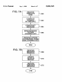
FIG. 78
RECEIVE
MESSAGE
FROM ICU
r\268
I
UPDATE
DELTA IN
BUFFER
II
RETURN
TIME/DATE
MESSAGE
I
END
\ 272
US. Patent
Sep. 1, 1998
FIG. 8A
RECEIVE
INPUT FROM
KEYPAD
I
CONSTRUCT
MESSAGE
I
BROADCAST
REQU EST
FOR TIM E/DATE
II
RECEIVE RESPONSE
FROM DATA
LOGGING UNIT
II
DISPLAY
TIME/DATE
END
FIG. 85
5,802,545
Sheet 7 of 7
RECEIVE
REQUEST FOR
TIME/DATE
II
COMPUTE
DRIVER LOCAL
TIME
I
BROADCAST
TIME/DATE
6D
x 280
5,802,545
1
2
METHOD AND SYSTEM FOR RECORDING
VEHICLE DATA RELATIVE TO VEHICLE
STANDARD TIME
zone is passed. In one embodiment, a master clock maintains
vehicle standard time, and also maintains driver local time.
One speci?c way to maintain driver local time is to keep
track of the dilference between the local time and the vehicle
time, and compute the local time, upon request, from the
vehicle standard time and the difference value.
The invention relates generally to data management and
storage systems for vehicles, and more speci?cally relates to
a vehicle clock capable of maintaining standard vehicle time
In one embodiment, a truck includes a data logging device
for recording vehicle performance data relative to vehicle
and a driver local time.
standard time. The data logging device monitors vehicle
BACKGROUND OF THE INVENTION
performance data such as road speed, engine speed, coolant
temperature, etc. provided by data measuring devices
throughout the vehicle. In the process of recording selected
data, the data logging device stamps instances of the data
In the trucking industry, it is important to accurately
maintain time for the bene?t of both the driver and for
service technicians. Since a truck driver frequently travels
across time zones, it is helpful to provide a clock in the cabin
that is easy to change with the change in time zones. In view
of this fact, it is quite common for trucks to have clocks in
the cabin that display time and can be reset to the local time.
Aside from the convenience to the driver, it is also useful to
have a clock for keeping track of vehicle operating and
diagnostic data. For example, if a problem occurs in the
with the vehicle standard time from a masta vehicle clock.
Time stamping refers to the process of associating vehicle
standard time with the data. This master clock in this
embodiment also maintains driver local time by keeping
track of the di?erence between local time and vehicle
standard time.
A local time display presents the local time in the cabin in
the vehicle. If the driver wants to change the local time, he
transmission, it is useful to know precisely when the prob
lem occlnred. Many of the sophisticated electronic controls
or she simply increments or decrements the time through an
the problem actually occurred at another time. This can
input control. Changes in local time are communicated to the
master clock. In one speci?c implementation, the input
control and time display are integrated into an instrument
control unit. This instrument control unit communicates
changes in local time to the mastu- clock, which keeps track
of the current difference between vehicle standard time and
driver local time.
Further advantages and features of the invention will
become apparent with reference to the following detailed
result when an electronic subsystem in a truck records a fault
description with refcence to the accompanying drawings.
in trucks do have a mechanism for keeping track of time.
Despite the presence of these electronics on board the truck,
the frequent changes in local time and/or the lack of a
consistency among time keepers in the vehicle often leads to
confusion in identifying when problems on the truck actu
25
ally occurred.
This confusion arises, for example, when a driver tells the
service technician that a problem occurred at one time and
using a time clock that is not consistent with the driver’s
time or time used by othm' subsystems in the vehicle.
35
It is equally confusing when a fault in a subsystem is
reeoniedatonetimeina?rsttimezone andthenisrecorded
again at the same time in a second time zone. Consider for
example, a truck travelling west from South Bend, Ind. to
Chicago, Ill. Iffaults arerecordedinterms oflocal time,
either by the driver or the truck’s electronics, it is possible
to record a fault at 2:00 PM. in South Bend and a second
fault at 2:00 PM. in Chicago. The resulting data erroneously
shows that the fault occurred twice at the same time, when
in reality, they occurred one hour apart.
The problems outlined above occur because of the lack of
etfective means for displaying and keeping track of time in
the truck. The di?culty in diagnosing problems in the
vehicle are fln'ther frustrated by the lack of effective systems
45
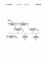
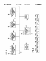
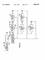
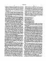
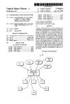
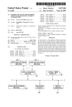
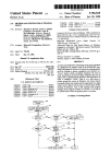
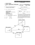
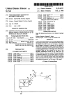
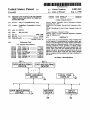
FIG. 1 is a functional block diagram illustrating a vehicle
data recording system of an embodiment of the invention.
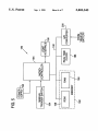
FIG. 2 is a block diagram illustrating the architecture of
data management system on a vehicle.
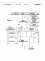
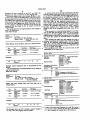
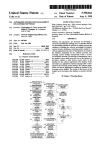
FIG. 3 is a block diagram illustrating an embodiment of
an instrument control unit in the data management system.
FIG. 4 is a diagram of the keypad of the instrument
control unit shown in FIG. 3.
FIG. 5 is block diagram illustrating the data logging unit
in one et of the invention.
FIG. 6 is a diagram illustrating one example of the display
screens used to set or change driver local time.
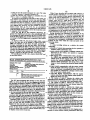
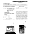
FIGS. 7A and 7B are ?ow diagrams illustrating a process
for setting the driver local time in one embodiment.
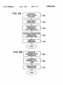
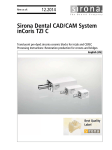
FIGS. 8A and 8B are ?ow
illustrating the
process for displaying local time in one embodiment.
fortracking andrecordingfaults detectedinthetruckln
general, that is a need for an e?'ective system for tracking
and recording events on a consistent basis and most prefer
ably across all subsystems installed in a truck.
SUMMARY OF THE INVENTION
BRIEI DESCRIPTION OF THE DRAWINGS
55
DETAILED DESCRIPTION
standard time and for conveniently displaying local time in
FIG. 1 is a ftmctional block diagram illustrating a vehicle
data recording system of an embodiment of the invention.
The system includes a plurality of data measuring devices
the cabin of the vehicle. The invention further provides a
master clock for maintaining vehicle standard time, and a
system for recording vehicle data. In this context, vehicle
Vehicle performance data can include a variety of vehicle
opa'ating, trip, maintenance or diagnostic data such as oil
standard time refers to a time reference or time standard in
pressure, road speed, fuel rate, coolant level, coolant
temperature, battery voltage, odometer ac. In addition, such
The invention provides a method for accurately recording
vehicle performance data relative to a master or vehicle
a truck against which the timing of performance data mea
sured throughout the vehicle may be recorded. Vehicle
(e.g. 20, 22, or 24) for measuring vehicle performance data.
vehicle performance data can include fault data such as oil
standard time can also serve as a reference point for com
pressure low, coolant tempa'ature high, high intake manifold
puting the local time displayed to the driver. Vehicle local
time is variable and is typically adjusted by a driver as a time
air temperature, electrical system or subsystem failure, etc.
The vehicle performance data can be measured indirectly via
5,802,545
3
4
sensors controlled by electronic control units, or directly via
discrete sensors or input devices. The data logging device 26
monitors vehicle performance data and potentially records
a data link 40. In particular, the system includes an instru
ment control unit 42, used to control instruments and gauges
at the dash of the truck, and a data logging unit 44, used to
monitor and record events reported on the data link 40. The
illustrated system architecture also includes a number of
other electronic units as shown, such as a powertrain ECU
selected instances or “slices” of this data. As alluded to
above, the data logging device can receive the vehicle
performance data either directly from a data measuring
device such as a discrete sensor or input device, or indirectly
through messages from electronic control units on a data
link. For example, sensors can include a coolant level sensor,
46, an air suspension ECU 48, an antilock brake ECU 50,
and an air conditioning protection unit 52. An ECU typically
includes a microprocessor, memory and one or more sensors
a battery voltage sensor, an input device located in the cab
of the truck etc. Similarly, the data logging device 26 can be
and actuators (54, 56, 58, 60, 62 and 64 for example) used
coupled to one or more electronic control units that measure
performance data and transfer it to the data logging device
via a data link.
The data logging device 26 can be prd to record
selected vehicle performance data in response to events. An
15
to control and/or monitor truck performance.
As one possible implementation, the devices depicted in
FIG. 1 can be implemented in the system architecture shown
in FIG. 2. In one embodiment, for example, the data logging
device and master clock are incorporated into the data
logging unit 44. The input control and the local time display
event can be a fault detected in the vehicle such as coolant
are features of the instrument control unit 42. Finally, the
data measuring devices may correspond to the electronic
control units. For instance, a data measuring device can be
level low or electrical subsystem failure. In addition, an
event can be a manually triggered signal or data message
sent to the data logging device. For instance in one speci?c
embodiment described further below, one type of event is a
implemented in an eledronic control unit, equipped with
sensors for meaning vehicle pu'formance data. As another
manually triggered event
by the driver. When used
in conjunction with the time tracking devices in the system,
example, a data measuring device can be implemented as a
discrete sensor directly coupled to the data logging unit.
this type of event is useful for tracking precisely when the
More detail regarding the instrument control unit and data
driver experiences problems.
Themastu'clock28is atimekeepingdevice thatmain
logging unit follows below.
tains vehicle standard time on the truck. Vehicle standard
The system architecture in FIG. 2 also includes a data port
70 for coupling external devices to the on-board data link.
time refers to a shared time resource or refa‘ence that
This dataport'lll enables an externalcomputa'toreceive
monotonically increases from a starting time, and acts as a
time reference for instances of vehicle data and events. The
master clock can be located in a variety of locations in the
truck. For instance, it can function as a stand alone device G‘
and transmit messages on the data link. It also enables an
external computer to establish a connection with an ECU on
the network to eitha' download data or retrieve data from
memory of an ECU on the data link.
can be in
into the data logging device 26, or other
The data link 40, in this implementation, is a serial
electronic control device in the vehicle such as an engine
computa- or an instrument control unit in the cabin. In one 35
embodiment, the mast: clock communicates vehicle stan
standard for serial data communication between microcom
dardtimetothedatalogging device sothatthe datalogging
puter systems in heavy duty vehicle applications. While this
device can reca'd the performance data relative to vehicle
standard time.
In addition to keeping vdricle standard time, the master
clock can also provide driver local time, which may or may
not dilfer from the vehicle standard time. In one speci?c
embodiment, the master clock
driver local time by
storing the ditfa'ence between driver local time and vehicle
standard time.
The local time display 30 shown in FIG. 1 displays the
speci?c embodiment is based on the J 1708 standard, it is not
critical that the invention be implemented in this speci?c
manna. One possible alternative is to use a data link
constructed according to SAE 11969.
Inone speci?cembodimenhthedatalink?is comprised
ofatwistedpaircableopcatingat9600bau¢Designed
45
diivulocaltimein?recaboftheu'uckltcanreceivethe
through a time zone, the driver can change the local time
easily by simply pressing a button on the input control to
change the local time displayed in the cabin. In one speci?c
embodiment, changes in local time are communicated to the
master clock, which maintains the current ditference or
“delta” between vehicle standard time and local time. More
detail regarding a speci?c implementation of the system in
accordingtotheSAEJ1708 standm'd, thedatalinkforms a
communication channel among electronic control units
coupled to it. Eectmnic control units generate a digital
signal on the data link by applying a voltage di?’erential
between the two wires in the cable. A voltage differential
above a speci?ed threshold represents a logic high value,
while a voltage threshold below a speci?ed threshold rep
resents a logic low value. This type of data link is particu
lomltimeeitherdirealyorindirectly?'omthemasterclock
28. In one speci?c embodiment, the local time display
receives the local time via the data logging device 26.
The input control 32 enables the driver to control the
display of driva' local time. Located in the cabin of the
truck, the input control enables the driver to increment or
decrement the local time. For example, if the truck passes
communication path connecting the ECUs togetha. This
particular data link is designed according to SAE 11708, a
larly advantageous for hostile environments because the
signal is more robust and impervious to signal degradation.
$5
However, other alternative communication media could be
used in place of the 11708 cable.
The ECUs connected on the network communicate with
each otheracoordingtoprotocols de?nedin SAE 11708 and
SAE 11587. The SAE 11587 standard is entitled “Joint
SAE/I‘MC Electronic Data Interchange Between Micro
computa' Systems and Heavy Duty Vehicle Applications.”
This standard de?nes the format of data and messages
communicated among microprocessors connected to a
FIG. 1 follows below.
FIG. 2 is a block diagram illustrating the system archi
shared data link, and is speci?cally adapted for use with
tecture in a more speci?c implementation of the system 65 SAE 11708.
shown in FIG. 1. The system architecture includes a numbe
According to SAE 11708/11587, the ECUs on the data
of electronic control units (ECU s) coupled togetha' in with
link commtmicate by passing messages to each other. The
5,802,545
5
6
ECUs can be either receivers. or receivers and transmitters.
controlling the ICU are stored in ROM 88, while con?g
urable data such as a con?giration ?le is stored in the
EEPROM 86.
The ICU also includes an input device 90 and a display
In this particular implementation, the instrument control unit
and the data logging unit are both transmitters and receivers.
A message includes the following: 1) a module 11) (MID),
2) one or more parameters, and 3) a checksum. The number
of parameters in a message is limited by the total message
length de?ned in the SAE J 1708 standard The message
identi?cation numbers are assigned to transmitter categories
device 92. In this implementation, the input device 90 is a
ten key keypad, and the display device 92 presents a
two-line display, sometimes referred to as the “message
center.” In one implementation, the display device com
prises a two by 20 character vacuum ?uorescent display.
as identi?ed in SAE 11587. The MID portion of a message
speci?es the origin or transmitter of the message. In the
Liquid Crystal Display (IJCD) or raster display device.
Alternative implementations are also possible such as a
majority of cases, messages are broadcast on the data link
The ICU can be connected to a number of sensors
without specifying a receiver. However, the message format
can be extended to include the MID of a receiver after the
(94-104) through analog to digital convertms 106. For
example, the ICU in this implementation is coupled to: door
MD) of the transmitter for special applications.
sensors (94) for detecting when the cab doors are open or
closed; HVAC sensors (96) for determining whether fresh
air is circulating in the cab; parking brake controls (98) for
sensing whether the parking brakes are applied; a coolant
level sensor (100) for detecting when the coolant level drops
below a speci?ed level; wiper ?uid sensors (102) for deter
mining when the wiper ?uid drops below a speci?ed level;
The messages passed among the ECUs to convey infor
mation by one or more parameters contained within the
messages. According to the SAE 11587 standard, the ?rst
character of every parameter is a parameter identi?cation
character (PD). The parameter identi?ed by the P11) directly
follows the F11). The SAE J 1587 supports di?erent data
formats including a single character, a double data character
or more than two data characters representing the parameter
data. Sevm‘al parameters can be packed into a message,
limited by the maximum message size as noted above.
and turn signal controls (104) which indicate when a turn
signal is applied.
The ICU can also include a buzzer 108 used to notify the
driver when certain warning conditions are deteded. Typical
examples of these warning conditions include “cab door
In this implementation, the ECUs communicate with each
open,” “parking brake applied and vehicle in motion,”
other over the data link according to the SAE standard
“coolant level low,” etc. In this implementation, the buzzer
11708. The standard describes methods for accessing the
data link and constructing messages for transfer over it. It
is integrated into the ICU. However, a buzmr or other audio
also de?nes a method for resource contention among the
ECUs on the data link.
ICU.
The particular ICU used in this implementation is manu
transducer can be implemented as a discrete device to the
AnECUwishingtotransmitdataonthedatalink?rst
factured by Joseph Pollak of Boston, Mass. for Freightliner
waitsforalullinu'ansmissionofdataonthedatalinklnthis
particular implementation, the length of the lull is 200
milliseconds. After detecting this lull, the ECU attempts to
Corporation. The instrument control unit is available as a
replacement part from Freightliner Corporation.
35
transmit its message. The transmitter broadcasts its message
onto the data link. Each of the ECUs that operate as receivers
on the data link will receive the message. However, receiv
FIG. 4 is a diagram of one implementation of the keypad.
The keypad includes the following dedicated keys:
ersonly acton amessageifprotodo so.
1.
2.
3.
4.
5.
In some cases two or more transmitters may attempt to
broadcast a message at one time, giving rise to a collision.
To resolve a con?ict among transmitters, messages have a
priority according to their message identi?ers. The PIDs of
higher priority p
have a greater number of bits set
at a logic level one. when more than one message is 45
broadcast at a time, the more dominant message takes
Time
Fuel
(120)
(122)
(124)
'Il-ip (miles, lows and fuel)
Leg (miles, hours and fuel)
(12:6)
(128)
The keypad also includes the following general purpose
keys:
priority over lesser dominant messages. Since a lower pri
ority message is blocked by a higher priority message, the
transmittu' of the lower priority message waits and retrans
mits the message afteranothcrluEAnECU on the datalink
will continue to attempt to send a message until it is
successfully broadcast to the data link.
1.
2.
3.
4.
Left Arrow Key
DawnAnow Key
Right Arrow Key
Set/Reset Key
(130)
(132)
(134)
(136)
The keypad includes an event key 138 which enables the
While this particular embodiment is implemented accord
driver to specify that an event or problem has occurred with
ing to the SAE J 1708 standard, this is only one example a
suitable data link implementation. Other alternatives are 55 the vehicle. For example, if the driver is experiencing
problems with the transmission, he can depress the event key
possible as well. For example, the data link can be imple
to record data associated with the transmission problem. In
mented according to SAE 11939.
response, the data logging unit 44 (FIG. 2) receives an
FIG. 3 is a block diagram illustrating the instrument
interrupt signal from the keypad 90 of the ICU (FIG. 3) and
control unit (ICU) in an embodiment of the invention.
creates an event ?le. In this implementation, there is a
Preferably located at the dash of the truck, the instrument
discrete connection 110 from the keypad 90 to the data
control unit can include the input control that enables a
logging unit 44. In addition, the ICU can send a message to
driva to display driver local time and to change the dis
played time as well.
driver or other user has triggered a manual event at the
The instrument control unit includes a CPU 80, memory
keypad 90.
82 and a portinterface 84 for connecting the unit to the data
Using the keypad, a user such as the driver or other
link 40. The memory includes programmable ROM
opa'ator is able to display and set driver local time. In this
(EEPROM) 86 and permanent ROM 88. The routines for
thedataloggingunitoverthedatalinkiltltonotifyitthatthe
5,802,545
7
8
particular embodiment. the ICU displays driver local time in
logging unit listens for periodic data messages broadcast
response to an input received from the “time” key in the
keypad. Driver local time includes the time in hours and
minutes (hhzmm AM. or RM.) and the date (month day,
year). The time and date can be displayed at any time in
response to the “time” key so long as the power to the dash
over the data link, and continuously records a snapshot of
data from the data link into a temporary storage device, such
as a FIFO bu?er. In this implementation, the data logging
unit is programmed to continuously store the most recent 60
seconds of data from the data link. Instances of vehicle
performance data can be captured at di?'erent intervals. For
example, data can be captured once a minute, twice a
minute, every second, or only when a prede?ned event is
of the truck is on.
To change or set the driver local time in this embodiment,
the user presses a sequence of keys on the keypad to retrieve
a set-up screen. For safety reasons, the set-up mode of the
ICU can only be activated when the parking brake is applied.
detected. Some examples of the data monitored by the data
Further detail regarding setting and changing driver local
time is provided below. Any available local time resetting
logging unit are set forth below. The name of the parameter
is followed by the parameter identi?cation number (PID) as
approach may be used.
FIG. 5 is block diagram illustrating the data logging unit
in one embodiment of the invention. In this implementation,
set forth in the SAE J 1587 standard.
15
the data logging unit incorporates the data logging device
and master clock shown in FIG. 1. The data logging unit 180
generally includes memory 182, a microcontroller 184, an
Output Torque; PD 93
Engine Oil Pressure; PID 100
Turbo Boost Pressure; P11) 102
Coolant Temperature; P11) 110
interface 186tothe datalink,arealtimeclock 188, anda
power supply 190. The memory 182 and the real time clock
are coupled to the microcontroller 184 via a bus 192.
The power supply 190 includes a chip that supplies power
Engine Speed (RPM); PD 190
to the microcontroller from either the vehicle battery or a
The data logging unit captures instances of selected data
lithium battery or other back up power supply. The lithium
once every second and stores it in the butter. When the butter
is full, the most recent second of data overwrites the oldest
battery serves as a back-up in the event that the voltage
supplied from the battery is insu?icient or unavailable.
As noted above, the data logging unit is coupled to the
keypad 90 of the ICU (FIG. 3) to receive an inta'rupt when
snapshot of data.
In addition to continuously storing slices of selected data,
the data logging unit also monitors prede?ned events. These
a user acmates the event key on the keypad. This connection
eventscanbede?nedbyaPlDbmadcastonthedatalink,
is represented by the manual lrigga switch 194 shown in
FIG. 5. The data logging unit can also receive interrupts
or by a discrete signal (such as an interrupt) received at the
data logging unit. When one of the prede?ned events occurs,
the data logging unit stores the last 60 seconds worth ofdata
from other devices as well. The keypad of the ICU could
also be coupled to the data logging unit to communicate
to memory and begins storing data following the event, such
signals representing changes in driver local time. For
example, a lney or keys on the keypad could be con?gured
tosend signals tothedataloggingunittoupdate crmodify
asthenextoOsecondsworthofdatalntotaltheamountof
35 data stored for an event includes two minutes and one
second worth of data in this particular implementation. This
local time, or the delta between vehicle standard time and
data is recorded in an event ?le in memory. An extanal
local time, stored in the data logging unit.
The memory 182 of the data logging unit includes both
RAM 196 and ROM 198. This implementation includes
128KB of ROM, which stores the application code exeerrted
by the microcontroller. This executable code includes the
set-up routines used to boot the data logging unit and the
data logging routines used to monitor prede?ned events.
‘This implementation also includes 256KB of battery-backed
RAM, which is used to implement a FIFO butter for
imparting data from the data link, to sure event ?les and to
sure a device
?le.
The data logging unit can monitor vehicle performance
datafromthedatalinkor?'omdiscretesensors coupled
directly to it. For example, the data logging unit monitors
voltage supplied by the vehicle battery through an analog to
digital converter 20., which converts the 12 volt signal from
the battery to a digital signal compatible with the microcon
troller 184.
The real time clock maintains vehicle standard or refer
ence time. Though the drive local time may be reset, for
example as the truck passes through time zones, the vehicle
standard time does not change with changes in the local
time. Instead, the vehicle standard time monotonically
increases from an
Vehicle standard time is helpful in
recording faults and events because it prevents ambiguity in
tracking when these faults or events occurred relative to
each other. Pln'ther detail regarding the operation of the
master clock and the local time display is provided below.
As introduced above, the data logging unit performs a
data monitoring function. Coupled to the data link, the data
Vehicle Road Speed; PH) 34
Percent Throttle; P11) 91
Percent Engine Load; P11) 92
compute’ can be used to extract one or more of these event
?les from the data logging unit for diagnostic purposes.
As noted above, the system architedure on-board the
vehicle maintains both vehicle standard time for tracking
events and faults and driver local time for display to the
45
driver. In the implementation described and illustrated
above, the data logging unit maintains vehicle standard time
and the di?’u'ence (delta) between vehicle standard time and
drivu' local time. In response to a request to display local
time at the keypad, the ICU issues a request for the time. The
data logging unit then returns the
time to the
ICU
FIG. 6 is a diagram illustrating one example of the display
screens usedto set or change driver local time. This diagram
shows a series of display sm'eens as well as the keys on the
keypad used to change smells and enter data. Starting with
the setup screen 220, the user accesses time/date setup
55 screens by using the arrow keys (222-226 fa- example) on
the keypad as shown. The user begins by strolling through
setup screens 228 to reach the main time/date screen 230.
When the user reaches the main time/date screen 230, he
or she can then set the minutes (232), hours (234), day (236),
month (238) and year (240) using the set key 242 and left
and right arrow keys 244, 246, for example. To exit the
time/date screens, the user can press the down arrow key
(248 fa‘ example). FIG. 5 represents only one example of
one implementation of a user interface for the ICU. A
nurnba- of other approaches are possible as well.
FIGS. 7A and 7B are ?ow diagrams illustrating a process
for setting the driver local time in one embodiment. FIG. 7A
5,802,545
10
As set forth in the above message speci?cations, the ICU
sends the change in time and/or data to the data logging unit
illustrates the steps executed by the ICU, and FIG. 7B
illustrates the steps executed by the data logging unit.
by specifying its MID (266). The data logging unit receives
the message or messages from the ICU (268, FIG. 7B), and
in response, updates values in a bulfer for storing the
difference (delta) between vehicle standard time and driver
The process begins when a user changes the time or date
from the setup screens as described above. The ICU receives
the data entered at the keypad when the user presses the set
key (260). It then computes the change in time or date of the
local time (270). In this particular implementation, the
driver local time (262). The ICU then constructs a message
to send to the data logging unit (264). Depending on what
battery backed RAM in the data logging unit includes this
memory buffer. The data logging unit adds a signed change
the user changes. a message or messages can be sent for the
in time to the cumulative time “delta” or “o?’se ” stored in
change in time, the change in date, or changes in both the
the buffer. Similarly for a change in date, it adds a signed
change in date to the cumulative date value stored in the
buffer.
As an alternative to communicating changes in local time
over the data link, the keypad of the ICU can be directly
time and date.
The speci?cation for one implementation of the change in
time is set forth below.
Delta Time Change
15
Priority:
8
Update Period:
Format:
As needed
MID_Ch1ster 254 M]D_Datnlogger
MessageJength
conneaed to the data logging unit to transfer data repre
senting changes in local time. In response, the data logging
unit would then update the time/date buffer as described
above.
31 MinuteJyte Hour_Byte
Aftm' updating the bulfer, the data logging unit sends a
message, transferring the updated time or date to the ICU
Checksum
(272). In this particular implementation, the data logging
unit issues a message using the 11587 standard parameters,
PID 251 inthe case ofanupdateintime,orPID252inthe
Where Minute_Byte and Hour_By1:e are as de?ned below:
caseofanupdateofthedate.
BY"
Minute
Hour
W
SignedShort
Imam
mm
lminutelbit
“In W
—60to+60minutes
Signed Short
1 hounlbit
—24 to +24 Innis
25
Integer
The speci?cation for PIDs 251 and 252 used in this
cmmdimgntmselfmbcbw
PID 251 - Clock
30 Parameter Data length:
Example:
3 Characters
Dnta'lypez
EachCharacter-UnsigiedShcrtImeg:
Resolut'nn:
Character 1 =0.25 dbit
Character 2 = 1 minlbit
140
254
179
a
a1
01
oo
Chmhlm
chum
Muirmnnllange:
Character1=0to63?$s
35
Character 2 = 0 to 255 min
Character 3 = 1 hlbit
Example requests displayed time be incremented by one
{Trim Paid‘ 011 must
minute‘
Message Primty:
The_ speci?cation for one implementation of the change in
Format:
date 1s set forth below.
"D
Delta Date Change
priority;
I
um mm
Fen-mat:
8
Data
4°
:51
11
nabe
Number of parameter data characters = 3
a
Seconds (mt displayed in this implementation)
8
b
Minutes
As me
wn_cmm 2.54 MID my
C
11°11"
WM
Where Da _B
Month__B
dc?ncd belzw: yte’
BODnyJy‘InMonthJyte
Yearjyie Checksum
and Year_B
yte,
ytb
‘5 "DZ-52'9"“
Parameter Data Inst!!!
Data Type:
are as
3 Characters
Each Character - Unsigned Short Image
Mm
W 1 = 0-15 WM‘
Character 2 = 1 imnthlbit
Ctmracter 3 = 1 year/bit
Chmacter1=0tn63?5day
50
Maximumkmge:
Character 2 = 0 to 255 month
Byte
The
Resolution
.
Day
Valid Range
Character 3 = 0 to 255 year
'
Signed Shut
0.25 day/bit
1'1"!"
Valid Range:
_
Month
StgnedShcrt
lmon?ilbit
Year
IQWN
Signed Short
ma"
.
1 yeadbit
W 2 =1 to 12 mm
55
—12to+12 unnths
179
mum period;
0am
Message Priority:
8
Format:
60
254
Character 3 = 0 to 255 year
—127 to +127 years
Exampk:
140
4
(?nancier-1:025 to 31.75 day
—31.75 to +31.7S days
30
FC
00
00
rm
pm
252
n abc
11
Number ofpmameterdatacharacters=3
a
Day
1:
Month
c
(Year - 1985)
Checksum
The Example shows the ICU sending a negative change of
one day to the data logging unit date buffers.
65 A value of O for the date (Character 1) is null. The values 1,
2, 3 and 4 are used to identify the ?rst day of the month; 5,
6, 7, and 8 identify the second day of the month etc.
'
5,802,545
11
12
A value of 0 for the month (Character 2) is null. The value
1 identi?es January; 2 identi?es February, etc.
A value of 0 for the year (Character 3) identi?es the year
1985, a value of 1 identi?es 1986, etc.
In response to the broadcast of the time or date update, the
ICU retrieves and displays the current time and date (274).
While I have described the invention with reference to
several specific embodiments, I do not intend to limit the
scope of my invention to these speci?c embodiments. The
master clock can be implemented in a variety of ways. It
need not be incorporated into a data logging unit, but
instead, could act as a stand alone device or could be
Although possible, preferably in this particular implemen
incorporated into another ECU. The data logging device can
be implemented in a variety of ways as well. It could be
designed to monitor vehicle performance data through dis
tation the ICU does not maintain a separate clock for driver
local time. Instead, it requests time as necessary from the
data logging unit. However, it is also possible to maintain
crete sensors or through ECUs coupled to a shared data link,
driver local time in the ICU. In an alternative
for example. The local time display and input control can be
implemented in a variety of ways as well. For instance, they
can implemented in an integrated dash control device such
implementation, the ICU could maintain the delta between
local and vehicle standard time, and use the local delta value
to compute driver local time.
FIGS. 8A and 8B are ?ow diagrams illustrating the
process for displaying local time in one embodiment. FIG.
as the instrument control unit, or in discrete devices.
Having described and illusn‘ated the principles of my
8A illustrates the steps executed by the ICU to request time
from the data logging unit, and FIG. 8B illustrates the steps
executing by the data logging unit in response to this request
for time.
invention with reference to a preferred embodiment and
several variations thereon, it should be apparent that the
invention can be modi?ed in arrangement and detail without
As shown in FIG. 8A, the process begins when a user
presses the time key on the keypad to request local time
(280). In response to this input, the ICU constructs a
?cations as may come within the scope and spirit of the
message requesting the time and date (282). The message
speci?cally includes the MD of the ICU, followed by PD)
128 and the MID of the data logging unit, which represents
a request for parameter transmission from the data logging
unit. The message further includes P11) 251 and 252 repre
senting a request for the time and date, respectively.
departing from its principles. Accordingly, I claim all modi
following claims.
l. A data recording system on a vehicle, the system
comprising:
25
a master vehicle clock operable to maintain vehicle stan
dard time for the vehicle, and operable to maintain
The speci?cation for P11) 128 is forth in SAE 11587 and
are provided below.
driver local time;
a data logging device communicative with a plurality of
the vehicle data measuring devices and the master
vehicle clock, the data logging unit being operable to
Pml28-Oomponentspec?hnnnterltequest-Usedbrequest
pammeterdstatranmnissims?omaspecifedmponemon?redatalitk.
PunmeterDataLeugth:
ZChar-aeters
Dan'lypez
Resolution:
Maximumkrrnge:
UnsignedShcr-tInteger-(botheharacten)
Binary(bcdrelnracters)
ODZSSMchIr-ucten)
35
Pl'D
clock;
128
ah
Parunetermnnberof?nlequested
b
clock, the input control being operable to receive user
input to decrement or increment the driver local time,
and opcable to communicate a change in driver local
time to the master vehicle clock;
a local time display communicative with the master
Data
I
vehicle clock, the local time display being operable to
display the driver local time.
moftheccmpcnentfromwhrchthe
pnmmeterrhtaisrequested
The ICU then broadcasts this message on the data link
(284). As shown in FIG. 8B, the data logging unit receives
this message and begins to prepare aresponse (286). In this
implementation, the data logging unit computes driver local
time by adding the cumulative offset stored in the buffer to
the vehicle standard time provided by the real time clock
monitor the vehicle performance data and to record
selected vehicle performance data along with a time
stamp in vehicle standard time from the mastu- vehicle
an input control communicative with the master vehicle
'lhnmrissbnUprbtePer-rod. Asneeded
MessagePr-brity:
8
M81:
a plurality of vehicle data measuring devices operable to
measure vehicle pu'fonnance data;
45
2.'l'hesystemofclaimlwherein?revehicledata
measuring devices include an electronic control unit with at
least one sensor for measuring vehicle pu'formance data.
3. The system of claim 1 wherein the vehicle data
measuring devices include at least one discrete sensor for
measuring vehicle performance data.
4. The system of claim 1 wherein the vehicle data
measuring devices include at least one elecn'onic control
(288). Similarly, it computes the date to be displayed with
driver local time by adding the cumulative offset for the date
wherein the vehicle performance data includes parameters
After computing driver local time, the data logging unit
transferred to the data logging device by the at least one
electronic control unit over the data link.
tothedateprovidedbytherealtimeclock(288).
constructs time and date messages and broadcasts them on
the data link (290). The format of these messages adheres to
the J 1587 standard for PlDs 251 and 252 as set forth above.
Returning again to FIG. 8A, the ICU is programmed to
receive the time and data messages (292). It then reads the
value for time and date provided in these messages and
displays the time and date on the display device (294).
The approach described above enables the data processing
system on the truck to monitor and record system-wide
events and faults with respect to vehicle standard time, and
to display correct driver local time.
unitcoupledtothedatalogging deviceviaadatalink, and
5. The system of claim 4 wherein data logging device is
opa'able to record the selected vehicle performance data and
time stamp in response to [rede?ned events.
6. The system of claim 5 wherein the prede?ned events
include a manually triggered event; whu'ein the input con
trol is operable to receive user input indicating the manually
triggered event, and the input control is communicative with
the data logging device to communicate the manually trig
gered event to the data logging device.
7. The system of claim 6 wherein the data logging unit is
opa'able to record selected vehicle performance data from
5,802,545
14
13
each of the plurality of vehicle measuring devices that has
been communicated to the data logging device from the
vehicle measuring devices over a period spanning before
and after the manually triggered event.
8. The system of claim 5 wherein the prede?ned events
sending a message including a change in the local driver
time to the data logging device; and
re-computing a new delta value from the stored delta
value and the change in the local driver time.
17. The method of claim 12 wherein the step of updating
the delta value includes:
communicating a change in the local driver time to the
master vehicle clock;
and re-computing a new delta value from the stored delta
value and the change in the local driver time.
18. A data recording system on a vehicle, the system
5
include a fault detected by the at least one electronic control
unit.
9. The system of claim 1 wherein the data logging device
and the master vehicle clock are part of a data logging unit.
10. The system of claim 1 wherein the input control, and
local time display are part of an instrument control unit
coupled to the data logging device via a serial data link.
comprising:
11. The system of claim 1 wherein the input control, and
the local time display are part of an instrument control unit,
wherein the data logging device and the master vehicle clock
a data link;
are part of a data logging unit, and wherein the instrument
control unit communicates the change in local driver time to
the data logging unit via a data link connecting the instru
transmit vehicle performance data on the data link;
the plurality of electronic control units including a data
logging unit, and an instrument control unit;
the data logging unit comprising a real time clock oper
able to maintain vehicle standard time, and memory
a plurality of electronic control units including sensors for
measuring vehicle performance data, and operable to
ment control unit and the data logging unit.
12. In a vehicle including a data logging device for as
monitoring and recording events, a method for recording
operable to store a delta value representing a ditference
between the vehicle standard time and driver local
vehicle data relative to vehicle standard time and for main
taining driver local time for display in a cabin of the vehicle,
time, the data logging unit being responsive to each of
the plm'ality of electronic control units for receiving
vehicle parameters from each of the electronic control
units and storing selected vehicle parameters along
the method comprising:
recording vehicle performance data relative to vehicle
standard time by stamping slices of the vehicle perfor
with a time indicator in vehicle standard time indicating
a time of occurrence of the corresponding parameter;
and
the instrument control unit comprising a display device, a
mance data with the vehicle standard time from a
master vehicle clock;
storing a delta value representing a difference between the
vehicle standard time and a driver local time;
computing the driver local time from me delta value and
the vehicle standard time;
displaying the driver local time in the cabin of the vehicle;
keypad and a microprocessor, the display device being
operable to display driver local time, the keypad oper
able to generate input signals representing an increment
in response to a user request to decrement or increment 35
the driver local time, updating the delta value to re?ect
the ditference between the vehicle standard time and
the driver local time;
monitoring for a manually triggered event entered into an
input device in the vehicle:
selected vehicle parameters from the electronic control
units over a period of time that includes a time of
stamp over a prede?ned period that includes a time of
occurrence of the manually triggered event.
occurrence of the manually triggered event in response
to the manually triggered event from the instrument
control unit.
13. The method of claim 12 wherein the step of recording
vehicle performance data includes:
19. A master vehicle clock in a truck comprising:
a real time clock operable to maintain vehicle standard
time for at least two electronic control units in the
from the data logging device, monitoring a data link for
faults transmitted by one or more eledronic control
units coupled to the data link and monitoring for the
truck;
manually triggered event from the input device; and in
a data logging device in communication with the elec
tronic control units and the real time clock: the data
response to detecting a ?rst fault, storing the slices of
vehicle performance data and time stamp over a pre
logging device being operable to butter vehicle perfor
de?ned period that includes a time of occurrence of the
?rst fault.
mance parameters from the electronic control units and
the data logging device being operable to write a set of
14. The method of claim 13 wherein the prede?ned period
the bu?’aed vehicle performance parameters along
rangesfromatimebeforethe?rstfaulttoatimeafterthe
with a vehicle standard time indicator to a ?le in
response to a user input event, where the set of butfered
?rst fault such that the step of storing the slices of vehicle
performance data includes storing a ?rst set of slices of
vehicle performance data occurring before the ?rst fault and
storing a second set of slices of vehicle performance data
occurring after the ?rst fault.
15. The method of claim 12 wherein the monitoring step
includes monitoring for a message representing the manu
ally triggered event transferred from an instrument control
unit to the data logging device over a data link.
16. The method of claim 12 wherein the step of updating
the delta value includes:
ing a manually triggered event, and the microprocessor
being operable to receive the input signals and in
response operable to communicate a change in drivd
local time and the manually triggered event to the data
logging unit over the data link
wherein the data logging unit is operable to store the
in response to detecting the manually triggered event,
storing the slices of vehicle performance data and time
.
and a decrement in the driver local time and represent
vehicle performance parameters is de?ned by a moving
period of time that includes a time of the user input
event,
memory communicative with the real time clock, the
memory operable to maintain a di?’erence between the
vehicle standard time and a driver local time;
65
local time display device communicative with the real
time clock, the local display device being operable to
display the local driver time in a cabin of the truck; and
5,802,545
15
16
an input control communicative with the real time clock,
recorded events and a set of vehicle parameters sent
the input control being operable to receive input from
from the vehicle data measuring devices within a
prede?ned period of the occurrence of the recorded
a user representing a change in the driver local time,
and operable to communicate the change to the real
time clock.
20. A data recording system on a vehicle, the system
events, the time stamps being responsive to time sig
nals from the master clock. whereby the time of an
event relative to vehicle standard time is recorded for
use in evaluating the event or diagnosing the cause of
comprising:
a plurality of vehicle data measuring devices operable to
measure vehicle performance data from a plurality of
vehicle subsystems;
a master clock maintaining a common vehicle standard
time for said plurality of vehicle data measuring
devices and generating time signals con'esponding to
vehicle standard time;
a data logging unit coupled to a plurality of the vehicle
data measuring devices and to the mastm' clock, the
data logging unit recording the occurrence of pre
de?ned events detected by the data logging unit from
data sent from the plurality of vehicle data measuring
devices and detected from manually entered input
during operation of the vehicle, the data logging unit
also recording time stamps in association with the
the event.
10
21. A data recording system according to claim 20 further
including a computm' selectively coupled to the data logging
unit and operable to download and display the recorded
events and time stamps for vehicle diagnostics.
22. A data recording system according to claim 21 further
including a local time clock operable to display a variable
local time.
2.3.Adatarecordingsystemaccordingtoclaim22in
which the local time clock is coupled to the master clock
with the local time being displayed in response to a di?er
ence signal representing the difference between the variable
local time and the vehicle standard time.
*****
UNITED STATES PATENT AND TRADEMARK OFFICE
CERTIFICATE OF CORRECTION
PATENT NO. : 5,802,545
DATED
: September 1, 1998
INVENTOR(S) : Cary N. Coverdill
Page 1 of 1
It is certified that error appears in the above-identified patent and that said Letters Patent is
hereby corrected as shown below:
Column 13 claim 12
Line 40, "vehiclez" should read -- vehicle; --.
Column 14 claim 19
Line 52, "clock:" should read -- clock; --.
Line 61, "event," should read -- event; --.
Column 16 claim 22
Line 13, "claim 21" should read -- claim 20 --.
Signed and Sealed this
Twenty-second Day of January, 2002
Arrest:
JAMES E. ROGAN
Arresting Officer
Director of the United States Patent and Trademark O?ice