1
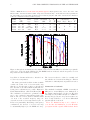
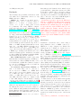
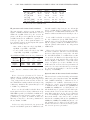
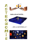
1
Proposals for IRAM Telescopes
The deadline for submission of observing proposals
on IRAM telescopes, both the interferometer and
the 30m, is
17 March 2011, 17:00 CET (UT + 1 hour)
The scheduling period extends from 1 June – 30 Nov
2011. Proposals should be submitted through our
web–based submission facility. Instructions can be
found on our web page at URL:
http://www.iram.fr/GENERAL/
submission/submission.html
to two pages of figures, tables, and references. Normal proposals should not exceed 6 pages, except for
additional technical pages. Longer proposals will be
cut. We continue to call for Large Observing Programmes (see P. Cox at the end of this Call for Proposals). The Large Programmes may have up to 4
pages for the scientific justification, plus cover page,
the technical pages, and 2 pages for supporting material.
The current versions of the proposal templates for
the 30m telescope prop-30m.tex and for the interferometer prop-pdb.tex must be used together with
the current LATEX style file proposal.sty. All three
files may be downloaded from
Detailed information on time estimates, special obhttp://www.iram.fr/GENERAL/submission/
serving modes, technical information and references
proposal.html
for both the IRAM interferometer and the IRAM
30m telescope can be found on the IRAM web site: Do not change the font type or size, and do not manipulate the style file. In case of problems, contact
http://www.iram-institute.org/
the IRAM secretary (e–mail: [email protected]).
and then following the links under Proposals. The Please, also indicate on the proposal cover page
submission facility will be opened about three weeks whether your proposal is (or is not) a resubmission
before the proposal deadline. Proposal form pages of a previously rejected proposal or a continuation
and the 30m time estimator are available now.
of a previously accepted interferometer or 30m proPlease avoid last minute submissions when the posal. We request that the proposers describe very
network could be congested. As an insurance against briefly in the introductory paragraph (automatically
network congestion or failure, we still accept, in well generated header “Proposal history: ”) why the projustified cases, proposals submitted by:
posal is being resubmitted (e.g. improved scientific
– fax to number: (+33) 476 42 54 69 or by
justification) or is proposed to be continued (e.g. last
observations suffered from bad weather).
– ordinary mail addressed to:
Short spacing observations on the 30m teleIRAM Scientific Secretariat,
scope
should directly be requested on the interfer300, rue de la piscine,
ometer
proposal form. A separate proposal for the
F-38406 St. Martin d’Hères, France
30m telescope is not required. The interferometer
Proposals sent by e–mail are not accepted. Color proposal form contains a bullet, labelled “30M short
plots will be printed/copied in grey scale. Proposals spacings” which should then be checked. The user
are evaluated on the basis of the paper copy. If color will be prompted to fill in an additional paragraph
is considered essential for the understanding of a in which the scientific need for the short spacings
specific figure, a respective remark should be added should be described. It is essential to give here all obin the figure caption. The referees may then consult servational details, including size of map, sampling
the electronic version of proposal.
density and rms noise, spectral resolution, receiver
Soon after the deadline the IRAM Scientific Sec- configuration, and time requested.
retariat sends an acknowledgement of receipt to the
A mailing list has been set up for astronomers inPrincipal Investigator of each proposal correctly re- terested in being notified about the availability of
ceived, together with the proposal registration num- a new Call for Proposals. A link to this mailing
ber. Note that the web facility allows cancellation list is on the IRAM web page. The list presently
and modification of proposals before the deadline. includes all principal investigators of proposals for
The facility also allows to view the proposal in its fi- IRAM telescopes during the last 2 years. Please vernal form as it appears after re–compilation at IRAM. ify that your email address in this list is correct.
We urge proposers to make use of this feature as
we always receive a number of corrupted proposals
J.M. Winters & C. Thum
(figures missing, blank pages, etc.).
Valid proposals contain the official cover page, one
or more pages of technical information, up to two
pages of text describing the scientific aims, and up
2
CALL FOR OBSERVING PROPOSALS ON THE 30M TELESCOPE
Travel funds for European
astronomers
Observations using IRAM telescopes continue to be
supported by RadioNet under the European Framework Programme 7. A budget, somewhat reduced
compared to the 2004 – 2008 period, is available for
travel by European astronomers through the Trans
National Access (TNA) Programme.
As before, travel may be supported to the
30m telescope for observation (contact: C. Thum)
and to Grenoble for reduction of interferometer data (contact: R. Neri). Detailed information
about the eligibility, policies, and travel claims
can be found on the RadioNet home page at
http://www.radionet-eu.org. The Principal Investigators of IRAM proposals eligible for TNA
funding will be informed individually.
Call for Observing
the 30m Telescope
Proposers are requested to use the time estimators which are available online via the IRAM 30m
webpage.
What is new?
Fourier Transform Spectrometers. The implementation and commissioning of the new Fast
Fourier Transform Spectrometers (FTS) is proceeding as planned. Two blocks of FTS are available
since 1-Dec-2010, each block covering a contiguous
4 GHz band. The spectral resolution of these FTS
is fixed to 195 kHz. This new backend is available
for regular observations with EMIR in all observing
modes, except for polarimetry.
Work is in progress (1) to increase the FTS bandwidth up to 32 GHz (at 195 kHz resolution) and (2)
to provide a higher spectral resolution of 50 kHz.
This change involves also a major upgrade of the IF
R. Neri & C. Thum sytem. If installation and commissioning work out
as planned, we expect that the expanded FTS features become available during the summer semester.
A more detailed description of the 32GHz FTS sysProposals on tem is given in the IRAM Newsletter of spring 2011.
EMIR upgrade. The large bandwidth of EMIR
will
be increased further during the semester. The
Summary
mixers used for the 230 and 330 GHz bands will be
Proposals for three types of receivers will be consid- replaced by dual sideband (2SB) mixers of the deered for the coming summer semester (1 June – 30 sign already installed for the E090 band. The E 230
Nov 2011):
and E 330 bands will then also have 32 GHz band1. the heterodyne receiver EMIR, consisting of width each (2 sidebands × 2 polarizations × 8 GHz
dual-polarization mixers, operating in the four of instantaneous bandwidth).
bands at 3, 2, 1.3, and 0.9 mm wavelengths.
New continuum backends We are installing
2. the 9 pixel dual–polarization heterodyne renew broadband continuum backends which fully
ceiver array, HERA, operating at 1.3 mm wavecover the bandwidth provided by EMIR. The curlength.
rent continuum detectors have a bandwidth of only
3. the MAMBO2 bolometer array with 117 pixels 1 GHz.
operating at 1.2 mm.
As none of the above three upgrades have yet been
commissioned on the telescope, we ask the proposers
Emphasis will be put on observations at the longer to base their estimates on the current available syswavelengths. Observations at wavelengths ≤ 1.3 mm tem. Use of the upgraded system will be on a ’shared
will be scheduled toward the end of the semester risk’ basis. Further information about the upgrades
in pools which allow to optimize the observations will be provided in due time to the community. Obaccording to weather conditions. The pool structure servers should make it clear in their proposals if
was successfully improved by including a new queue the expanded features are essential in reaching their
for projects requiring the ”best weather”. Projects goals.
in this new queue are observed when the column
of preciptable water vapor drops below 2mm and
when other practical conditions (wind, atmospheric The complete text of the Call for Proposals can
be retrieved as a pdf file from the IRAM web site at
stability) are fulfilled.
We continue to call for Large Programmes using
http://www.iram.fr/GENERAL/
any of the three instruments.
calls/s11/s11.pdf
3
EMIR
Non-trivial changes with respect to the previous Call
for Proposals are marked in red.
C. Thum & C. Kramer
Applications
The official proposal cover page and the second page
for the Technical Summary should be filled in with
great care. All information on these pages is transferred to the IRAM proposal database. Attention
should be given to Scheduling constraints where the
proposer can enter dates where he/she is not available for observing. Proposers requesting observations which need atmospheric opacities better than
typical for the semester (corresponding to 7mm pwv
in summer and 4mm in winter) should give the maximum acceptable value of precipitable water vapor in
the corresponding table of the Technical Summary.
In order to avoid duplication of observations and
to protect already accepted proposals, we keep a
computerized list of targets. We ask you to fill in
carefully the source list in equatorial J2000 coordinates. This list must contain all the sources (and
only those sources) for which you request observing time. Your list must adhere to the format indicated on the proposal form (sexagesimal notation).
If your source list is longer than 15 sources that
fit onto the cover page, please use the LATEXmacro
\extendedsourcelist.
A scientific project should not be artificially cut
into several small projects, but should rather be submitted as one bigger project, even if this means
100–150 hours of observing time. Note that large
programs of particular scientific importance can be
submitted in the “Large Programmes” category.
If time has already been given to a project but
turned out to be insufficient, explain the reasons,
e.g. indicate the amount of time lost due to bad
weather or equipment failure; if the fraction of time
lost is close to 100%, don’t rewrite the proposal,
except for an introductory paragraph. For continuation of proposals having led to publications, please
give references to the latter.
EMIR
Overview
The spectral line receiver EMIR (Eight MIxer
Receiver) which was installed in spring 2009 is operational without any major complications. The receiver operates in the 3, 2, 1.3 and 0.9 mm atmospheric windows (Fig. 1), in each of which it provides two orthogonal linear polarization channels.
EMIR offers very competitive noise temperatures, a
stable alignment between polarizations and bands,
and other practical advantages.
The four EMIR bands are designated as E 090,
E 150, E 230, and E 330 according to their approximate center frequencies in GHz. Tab. 1 shows
the main current characteristics of EMIR and indicates the upgrades planned during the summer
semester. Three bands will then be equipped with
two–sideband (2SB) mixers, and only the E150 band
has a single sideband (SSB) mixer. The 2SB mixers
offer 8 GHz of instantaneous bandwidth per bandwidth and polarization, whereas the SSB mixer has
only 4 GHz per polarization. After the upgrade the
total EMIR bandwidth will increase from 64 to 104
GHz, of which up to 32 GHz are available simultaneously.
Both polarizations of a given band will always be
tuned to the same frequency as they share a single
common local oscillator. The tuning ranges of the
4 bands and the typical receiver noise temperatures
are listed in Tab. 1. The image band rejection gi as
measured in the laboratory is always better than 10
db. The observer at the telescope cannot however remeasure anymore this sometimes critical quantity.
Below the lower frequency end of the tuning range
(ν < 83 GHz) the behavior of gi must be expected
to be erratic, and such observations are therefore
discouraged.
EMIR provides a permanently available high sensitivity E 330 band, opening this atmospheric window for regular use under very good weather conditions. The frequency range of this band (see Tab. 1),
currently limited at the upper end by LO power, is
planned to be extended up to 360 GHz.
Selection of EMIR bands
Before reaching the Nasmyth mirrors, the beams of
the four EMIR bands pass through warm optics that
contain switchable mirrors and dichroic elements for
redirection of the beams towards calibration loads
and for combining beams. In its simplest mode, the
warm optics unit selects one single EMIR band for
observation. This mode avoids the use of the slightly
4
CALL FOR OBSERVING PROPOSALS ON THE 30M TELESCOPE
Table 1: EMIR Frontend, current status and planned upgrades. Sky frequencies, Fsky , refer to the center of the
IF band. 2SB – dual sideband mixers, SSB – single side band mixers, H/V – horizontal and vertical polarizations,
Tsb is the SSB receiver temperature in single band observations (left). For dual–band observations, Tdb includes a
15 K noise contribution from the dichroics (right).
EMIR
band
Fsky
GHz
mixer
type
polarization
bandwidth
GHz
Tsb
K
Gim
dB
E 090
E 150
E 230
E 330
83 – 117
129 – 174
200 – 267
260 – 350
2SB
SSB
SSB→2SB
2SB
H/V
H/V
H/V
H/V
8
4
4→8
4→8
50
50
50
70
> 13
> 10
> 13
> 10
combinations
E 0/2 E 1/3 E 0/1
X
X
X
X
X
X
Tdb
K
65
65
65
85
Figure 1: Atmospheric transmission at the 30m site between 60 and 400 GHz for 1 and 4mm of precipitable
water vapor, derived from the ATM model. The EMIR bands are indicated and the frequencies of a few
important molecular transitions are marked.
lossy dichroic elements and therefore offers the best The observer is therefore advised to carefully evaluate whether an observation involving two different
receiver noise temperatures.
bands is more efficiently made in parallel or in series.
The warm optics includes dichroic mirrors which
combine the beams of two receivers in such a way
that they look at the same position on the sky and Connection to backends
have the same focus values within 0.3mm. The following band combinations are possible: E 090 and The remarkable bandwidth of EMIR of currently 64
E 150, E 090 and E 230, or E 150 and E 330 (Tab. 1). GHz (and soon 104 GHz) faces two limitations of
The combination of bands is not polarization selec- the existing 30m hardware: (1) the four IF cables
tive, i.e. the combined beams will stay dual polar- can transport only 4 GHz each (the 4 × 4 GHz botization. The loss of these dichroics which is small tleneck) and (2) only at low spectral resolution are
over most of the accessible frequency range, in- there enough backends to cover the 16 GHz which
creases however the receiver temperatures by 10 – 15 pass through the bottleneck.
These two limitations may soon be relaxed or
K. In a few particularly disadvantageous frequency
combinations, the increase of receiver noise may overcome after the installation of a new IF transbe substantially higher (see the EMIR web site). port system and the expanded FTS backend. In the
HERA
5
single–sideband mixers; DSB tuning is not possible, but sidebands (USB or LSB) may be selectable
within limitations. The image rejection is better
than 10 dB for all frequencies. On–site measurements of the rejection is not longer straightforward
for these mixers, since the Martin–Puplett interferometers are not available anymore for sideband separation. As the optimum way of calibrating the image rejection is still under study, users who propose
observations which rely on an enhanced accuracy of
calibration of image gains should mention this request in the proposal.
Bands E 090 and E 330 have tunerless sideband
separation mixers, allowing simultaneous observations of both sidebands in separate IF bands. These
mixers have been characterized in the laboratory for
their image rejection and are expected to have the
The WILMA processor rearranges the four same performance on site (> 10 dB). The default
incoming 4 GHz wide IF channels into 16 chan- rejection for all EMIR receivers, is 13dB.
nels of 1 GHz width which can be processed
by 16 WILMA autocorrelator units. Since each
unit provides 512 spectral channels of 2 MHz, Velocity scales
sufficient backend power is available at this low It is common practice at radio observatories to corspectral resolution for full coverage of the 4 × 4 rect the frequency of an observation for the strongly
GHz bottleneck.
time variable velocity of the Observatory with re-
following, we describe however only the current situation.
A IF switch box in the receiver cabin allows to
select 4 EMIR channels of 4 GHz bandwidth each
from 16 inputs.1 The box can handle all plausible
single band observations as well as the band combinations indicated in Tab. 1. A full list of possible
switch settings is available on the EMIR home page
in Granada.
The selected 4 output channels are sent via the IF
cables to a backend distribution unit which provides copies of these 4 channels to a range of backend
processors which then prepare the IF signals for distribution to the spectrometers. The following three
backend processors feed the 4 GHz wide IF channels
to the backends:
The 4 MHz processor rearranges any two incoming 4 GHz wide IF channels into 8 slices of
1 GHz width for processing in 8 units of the 4
MHz filter bank. 2×4 GHz of EMIR bandwidth
are thus covered at 4 MHz resolution.
The “narrow band backends” processor
prepares the 4 incoming IF channels for input
into VESPA. Only the central part of the 4 GHz
IF channels is accessible to this backend. Inside
the central part (640 MHz), VESPA can be configured as before. Note however that VESPA
bands cannot be moved outside the ±250 MHz
range around the band center. The VLBI terminal is also fed from this processor.
Calibration Issues
spect to the solar system barycenter. This guarantees that lines observed near the Doppler–tracked
frequency, usually the band center, always have the
correct barycentric velocity, independent of the time
of observation. However, the effect of the Observatory’s motion on the velocity scale which affects
most the velocity channels farthest away from the
Doppler–tracked frequency, is usually ignored.
This effect which is of the order of 10−4 cannot be
neglected anymore if large bandwidths are used, as
with EMIR. The worst case occurs with band E 090
where channels as far away as 20 GHz need to be
considered if a velocity channel in one of the sidebands is Doppler–tracked. In unfavorable but nevertheless frequent cases (target source not too far
from the ecliptic, like the Galactic center), errors of
up to ±2 MHz occur. Since the magnitude of the
error changes with time, narrow spectral lines may
be broadened after a few hours of observation, and
spectra taken at different epochs may not align in
frequency.
EMIR has its own calibration system. The external warm optics provides ambient temperature loads
and mirrors reflecting the beams back onto the 15 K
stage of the cryostat. This system is expected to be
very reliable and constant over time. Absolute calibration accuracy will be better than 10% with EMIR HERA
when all details are well settled.
A full description of HERA HEterodyne Receiver
Bands E 150 and E 230 have backshort tuned Array and its observing modes is given in the
HERA manual. Here we only give a short summary.
1 The 4 channels of 8 GHz width available from E 090 are
The 9 dual–polarization pixels are arranged in the
rearranged by the IF switch box into 4 pairs of inner and
outer 4 GHz wide channels.
form of a center–filled square and are separated by
6
CALL FOR OBSERVING PROPOSALS ON THE 30M TELESCOPE
24′′ . Each beam is split into two linear polarizations
which couple to separate SIS mixers. The 18 mixers
feed 18 independent IF chains. Each set of 9 mixers is pumped by a separate local oscillator system.
The same positions can thus be observed simultaneously at any two frequencies inside the HERA tuning range (210-276 GHz for the first polarization,
and 210-242 for the second polarization).
A derotator optical assembly can be set to keep
the 9 pixel pattern stationary in the equatorial or
horizontal coordinates. Receiver characteristics are
listed on the 30m web site.
Recent observations have shown that the noise
temperature of the pixels of the second polarization
array may vary across the 1 GHz IF band. The highest noise occurs towards the band edges which are,
unfortunately, picked up when HERA is connected
with VESPA whose narrow observing band is located close to the lower edge of the 1 GHz band.
Therefore, while not as important for wide band observations with centered IF band, the system noise
in narrow mode is higher (factor 1.5 – 2) as compared to the first polarization array. We do not recommend to use the second polarization for frequencies > 241 GHz.
HERA can be connected to three sets of backends:
limitations of OTF line maps, as described in the
HERA User Manual, due to baseline instabilities
induced by residual calibration errors. HERA proposers should use the web–based Time Estimator.
For details about observing with HERA, consult
the User Manual. The HERA project scientist, Karl
Schuster ([email protected]), or Manuel Gonzalez
([email protected]), the HERA pool coordinator,
may also be contacted.
Accepted HERA proposals will be pooled together in order to make more efficient use of stable
1.3mm observing conditions. Questions concerning
the HERA pool organization can be directed to the
scheduler or the HERA pool coordinator.
MPIfR Bolometer array
The bolometer array MAMBO–2 (117 pixels) is
provided by the Max–Planck–Institut für Radioastronomie. It consists of concentric hexagonal rings
of horns centered on the central horn. Spacing between horns is ≃ 20′′ . Each pixel has a HPBW of
11′′ .
The effective sensitivity of MAMBO–2 for onoff
1
1
observations is ∼ 40 mJy s 2 and ∼ 45 mJy s 2 for
mapping. The rms, in mJy, of a MAMBO–2 map is
typically
p
VESPA with the following combinations of
rms = 0.4f vscan ∆s
nominal resolution (kHz) and maximum bandwidth (MHz): 20/40, 40/80, 80/160, 320/320, where vscan , in arc sec/sec, is the velocity in the
1250/640. The maximum bandwidth can actu- scanning direction and ∆s, in arc sec, is the step
ally be split into two individual bands for each size in the orthogonal direction. The factor f is 1
of the 18 detectors at most resolutions. These (2) for sources of size < 30′′ (> 60′′ ). It is assumed
individual bands can be shifted separately up to that the map is made large enough that all beams
±250 MHz offsets from the sky frequency (see cover the source. The sensitivities apply to boloalso the sections on backends below).
metric conditions (stable atmosphere, τ (250GHz) ∼
a low spectral resolution (4 MHz channel spac- 0.3, elevation 45 deg, and application of skynoise
ing) filter spectrometer covering the full IF filtering algorithms). In cases where skynoise filterbandwidth of 1 GHz. Nine units (one per HERA ing algorithms are not or not fully effective (e.g. expixel) are available. Note that only one polar- tended source structure, atmosphere not sufficiently
ization of the full array is thus connectable to stable), the effective sensitivity is typically about a
factor of 2 worse. The principal investigators of acthis filter bank.
cepted proposals will be requested to specify in the
WILMA with a 1 GHz wide band for each of pool database which minimum atmospheric condithe 18 detectors. The bands have 512 spectral tions their observations need.
channels spaced out by 2 MHz.
The bolometer arrays are mostly used in two baHERA is operational in two basic spectroscopic sic observing modes, ON/OFF and mapping. Preobserving modes: (i) raster maps2 of areas typically vious experience with MAMBO–2 shows that the
not smaller than 1′ , in position, wobbler, or fre- ON/OFF reaches typically an rms noise of ∼ 2.3
quency switching modes, and (ii) on–the–fly maps mJy in 10 min of total observing time (about 200
of moderate size (typically 2′ − 10′ ). Extragalac- sec of ON source, or about 400 sec on sky integratic proposals should take into account the current tion time) under stable conditions. Up to 30 percent
lower noise may be obtained in perfect weather. In
2 As long as the NCS raster command is not operational,
the raster pattern has to be traced out with the help of a SIC this observing
√ mode, the noise integrates down with
loop.
time t as t to rms noise levels below 0.4 mJy.
7
The Telescope
In the mapping mode, the telescope is scanning
in the direction of the wobbler throw (default: azimuth) in such a way that all pixels see the source
once. A typical single map3 with MAMBO–2 covering a fully and homogeneously sampled area of
150′′ × 150′′ (scanning speed: 5′′ per sec, raster step:
8′′ ) reaches an rms of 2.8 mJy/beam in 1.9 hours
if skynoise filtering is effective. Much more time is
needed (see Time Estimator) if sky noise filtering
cannot be used. The area actually scanned in this
typical map must be much larger, namely (8.0′ ×6.5′ )
if the EHK–algorithm is used to restore properly extended emission. This is because the wobbler throw,
the array size (4′ ), the source extent, and some
margin for baseline determination must be added.
Shorter scans may lead to problems in restoring extended structure. Mosaicing is also possible to map
larger areas. Under many circumstances, maps may
be co–added to reach lower noise levels. If maps with
< 1 mJy are proposed, the proposers should
an rms ∼
contact Robert Zylka ([email protected]).
The bolometers are used with the wobbling secondary mirror (wobbling at a rate of 2 Hz). The
orientation of the beams on the sky changes with
hour angle due to parallactic and Nasmyth rotations, as the array is fixed in Nasmyth coordinates
and the wobbler direction is fixed with respect to
azimuth during a scan. Bolometer proposals participating in the pool have their observations (maps
and ONOFFs) pre-reduced by a data quality monitor which runs scripts in MOPSIC. This package,
complete with all necessary scripts, is also installed
for off-line data analysis in Granada and Grenoble. It is also available for distribution from the
GILDAS web page[5].
Bolometer proposals will be pooled together like
in previous semesters along with suitable heterodyne
proposals as long as the respective PIs agree. The
web–based time estimator handles well the usual
bolometer observing modes, and its use is again
strongly recommended. The time estimator uses
rather precise estimates of the various overheads
which will be applied to all bolometer proposals. If
exceptionally low noise levels are requested which
may be reachable only in a perfectly stable (quasi
winter) atmosphere, the proposers must clearly say
so in their time estimate paragraph. Such proposals will however be particularly scrutinized. On the
other extreme, if only strong sources are observed
and moderate weather conditions are sufficient, the
proposal may be used as a backup in the observing
3
see also the Technical report by D. Teyssier and A. Sievers on a special fast mapping mode (IRAM Newsletter No. 41,
p. 12, Aug. 1999).
pool. The proposal should point out this circumstance, as it affects positively the chance that the
proposal is accepted and observed.
Questions concerning the MAMBO pool organization can be directed to the scheduler ([email protected])
or to the MAMBO pool coordinator, Guillermo
Quintana-Lacaci ([email protected]).
The Telescope
This section gives all the technical details of observations with the 30m telescope that the typical user
will have to know. A concise summary of telescope
characteristics is published on the IRAM web pages.
Pointing and Focusing
With the systematic use of inclinometers the telescope pointing became much more stable. Pointing
sessions are now scheduled at larger intervals. The
fitted pointing parameters typically yield an absolute rms pointing accuracy of better than 3′′ [7].
However, larger deviations can occur around sunset or sunrise, in which case we recommend more
frequent pointings (every 1 or 2 hours, depending
on the beam size). The eight individual receivers of
EMIR are very well aligned with each other. Offsets
between polarizations of any one band are smaller
than 1′′ and offsets between bands have been measured to be below 2′′ . Checking the pointing, focus,
and receiver alignment is the responsibility of the
observers (use a planet for alignment checks). Systematic (up to 0.4 mm) differences between the foci
of various receivers can occasionally occur. In such
a case the foci should be carefully monitored and
a compromise value be chosen. Not doing so may
result in broadened and distorted beams [9].
Wobbling Secondary
– Beam–throw is ≤ 240′′ depending on wobbling
frequency. At 2 Hz, the maximum throw is 90′′
– Standard phase duration: 2 sec for spectral line
observations, 0.26 sec for continuum observations.
Unnecessarily large wobbler throws should be
avoided, since they introduce a loss of gain, particularly at the higher frequencies, and imply a loss of
observing efficiency (more dead time).
Beam widths and Efficiencies
See the summary of telescope parameters on the
Granada web site for the current efficiencies between 70 and 270 GHz, and the predictions for the
8
CALL FOR OBSERVING PROPOSALS ON THE 30M TELESCOPE
345 GHz (0.9 mm) band.
Backends
The following four spectral line backends are available which can be individually connected to any
EMIR band and to HERA.
VESPA, the versatile spectrometric and polarimetric array, can be connected either to
HERA or to a subset of 4 single pixel receivers, or to a pair of single pixel receivers
for polarimetry. The many VESPA configurations and user modes are summarized in a
Newsletter contribution [10] and in a user guide,
but are best visualised on a demonstration program which can be downloaded from our web page
at http://www.iram.fr/IRAMFR/PV/veleta.htm.
Connected to a set of 4 IF schannels of EMIR,
VESPA typically provides up to 12 000 spectral
channels (on average 3 000 per receiver). Up to
18 000 channels are possible in special configurations. Nominal spectral resolutions range from 3.3
kHz to 1.25 MHz. Nominal bandwidths are in the
range 10 — 512 MHz. VESPA basebands can be
offset from band center up to ±250 MHz (outer
edges of the baseband). When VESPA is connected
to HERA, up to 18 000 spectral channels can be used
with the following typical combinations of nominal
resolution (kHz) and maximum bandwidth (MHz):
20/40, 40/80, 80/160, 320/320, 1250/640.
The 4 MHz filterbank consists of nine units.
Each unit has 256 channels (spacing of 4 MHz, spectral resolution at 3 dB is 6.2 MHz) and thus covers a
total bandwidth of 1 GHz. The 9 units are designed
for connection to HERA, but a subset of 4 units can
also be connected to EMIR.
The wideband autocorrelator WILMA consists of 18 units. They can be connected to
the 18 detectors of HERA or to EMIR. Each
unit provides 512 spectral channels, spaced out
by 2 MHz and thus covering a total bandwidth of 1 GHz. Each band is sliced into two
500 MHz subbands which are digitized with
2 bit/1 GHz samplers. An informative technical
overview of the architecture is available at URL4
../IRAMFR/TA/backend/veleta/wilma/index.htm.
A Fast Fourier Transform Spectrometer
(FTS) is being implemented as a new backend for
use with the heterodyne receivers. It consists of a
series of FTS modules purchased from Radiometer
Physics. Each module is currently configured to digitize an IF band of 1.5 GHz width and to give more
4 URL addresses preceded by two dots (..) are relative to
http://www.iram.fr/
than 8000 spectral channels. In the initial version
operational in the coming winter semester, two FTS
blocks will be available where each block combines
3 modules to give a contiguous 4 GHz band with
a spacing between channels of 195 kHz. Each block
can be connected to any of the 4 GHz IF signals of
EMIR in parallel to the 4 MHz filterbank.
Work is in progress (1) to increase the FTS bandwidth up to 32 GHz (at 195 kHz resolution) and (2)
to provide a higher spectral resolution of 50 kHz. If
installation and commissioning work out as planned,
we expect that the expanded FTS features become
available during the summer semester. Observers
should make it clear in their proposals if the expanded features are essential in reaching their goals.
A more detailed description of the expanded FTS
backend is given in the IRAM Newsletter of February 2011.
Polarimetry
Polarimetric observations can be made using a
dual–polarization band of EMIR connected to
VESPA in a setup designated as XPOL. The
technical aspects of XPOL are described in detail for the previous generation of heterodyne receivers (Thum et al. [13]), together with its observing capabilities and limitations. The adaptation to EMIR is described in a technical note
http://www.iram.es/IRAMES/mainWiki/CalibrationPapers?action=A
2010-polarimetry-v3.pdf Most notably, XPOL generates simultaneous spectra of all 4 Stokes parameters. The following combinations of spectral resolution (kHz) and bandwidth (MHz) are available:
40/120, 80/240, and 320/480. More complex observing modes where VESPA is split into two bands are
also possible (see the VESPA user guide[10]).
XPOL has been tested for the EMIR bands E 090
and E 230 (see the technical note). XPOL profits
from the improved performance of EMIR in several respects: smaller or negligible phase drifts, small
and stable offsets between the two polarizations, and
negligible decorrelation losses.
Polarized sidelobes, albeit smaller than typically
observed with the previous receivers, are still complicating observations of extended sources. Current
evidence indicates that the rotation of the sidelobes
with elevation is more complicated than with the
previous receivers, possibly due to the off–axis installation of EMIR. Proposals for observation of extended sources should demonstrate that their observations are feasible in the presence of the known
sidelobes.
Proposals for polarimetric observations may be
9
Organizational aspects
submitted for EMIR bands E 090 and E 230. Polarimetry using the bands E 150 and E 330 has
to wait for additional hardware and commissioning. Astronomers interested in using XPOL are invited to check with Helmut Wiesemeyer or Clemens
Thum.
Organizational aspects
Pooled observing
This matter needs special attention as a serious time
underestimate may be considered as a sure sign of
sloppy proposal preparation. We strongly recommend to use the current time estimator on–line at
the Granada web site. which handles EMIR, HERA,
and MAMBO2.
If very special observing modes are proposed
which are not covered by the Time Estimator, proposers must give sufficient technical details so that
their time estimate can be reproduced. In particular,
the proposal must give values for Tsys , the spectral
resolution, the expected antenna temperature of the
signal, the signal/noise ratio which is aimed for, all
overheads and dead times, and the resulting observing time.
Proposers should base their time request on normal summer conditions, corresponding to 7 mm of
precipitable water vapor (pwv). Conditions during
afternoons can be degraded due to anomalous refraction. The observing efficiency is then reduced
and the flux/temperature calibration is more uncertain than the typical 10 percent (possibly slightly
more for bolometer observations).
Proposers requesting observations which need
pwv values lower than 7mm should enter the maximum acceptable pwv value on the Technical summary page. Very demanding proposals, e.g. observations using E 330 above 300 GHz, or some very deep
and/or high frequency continuum observations, may
need pwv values ≤ 2mm. These observations will be
scheduled in a pool.
As in previous semesters, we plan to pool the accepted high frequency (λ ≤ 1.3mm) proposals. This
includes bolometer, HERA, and those EMIR proposals which principally request the E 230 and E 330
bands. These high frequency proposals will be combined with less weather dependent proposals at
lower frequencies in several pool sessions. Proposals
with particularly strong demands on weather quality (e.g. heterodyne observations at ν > 300 GHz,
very deep bolometer maps) will be included in these
pools where they get precedence as soon as the precipitable water vapor column (pwv) falls below 2mm
and other conditions are fullfilled. A correct specification of the pwv on the technical summary page is
therefore very important.
The proposals participating in the pools will
be observed by the PIs and Co-PIs of participating projects, and IRAM staff. The pool observations will be organized by the pool coordinators, Guillermo Quintana-Lacaci (MAMBO2/1) and
Manuel Gonzalez (HERA). The participating proposals are grouped according to their demand on
weather quality, and they get observed following the
priorities assigned by the program committee. The
organization of the observing pools are described on
the spanish web site.
Bolometer and heterodyne proposals which are
particularly weather tolerant qualify as backup for
the pools. Participation in the pools is voluntary,
and the respective box on the proposal form should
be checked.
Questions concerning the pool organization can
be directed to the scheduler ([email protected])
or the Pool Coordinators, Guillermo QuintanaLacaci ([email protected]) and Manuel Gonzalez
([email protected]).
Frequency switching
Service observing
Frequency switching is available for both HERA polarizations as well as for EMIR. This observing mode
is interesting for observations of narrow lines where
flat baselines are not essential, although the spectral
baselines with HERA are among the best known in
frequency switching. Certain limitations exist with
respect to maximum frequency throw (≤ 45 km/s),
backends, phase times etc.; for a detailed report
see [2]. This report also explains how to identify
mesospheric lines which may easily be confused in
some cases with genuine astronomical lines from cold
clouds.
To facilitate the execution of short (≤8 h) programmes, we propose “service observing” for some
easy to observe programmes with only one set of tunings. Observations are made by the local staff using
precisely laid–out instructions by the principal investigator. For this type of observation, we request
an acknowledgement of the IRAM staff member’s
help in the forthcoming publication. If you are interested in this mode of observing, specify it as a
“special requirement” in the proposal form. IRAM
will then decide which proposals can actually be accepted for this mode.
Observing time estimates
10
Remote observing
This observing mode where the remote observer
actually controls the telescope very much like on
Pico Veleta, is available from the IRAM offices in
Granada and Grenoble, and from the MPIfR Bonn,
and from OAN in Madrid. If you are planning to use
remote observing, please contact the Astronomer
on Duty (for Granada), Clemens Thum (for Grenoble), J. Alcolea (for Madrid), or Dirk Muders (for
Bonn) well in advance of your observing run. As a
safeguard, please email observing instructions and
macros to the AoD and/or operator.
In special cases, experienced observers may conduct remote observations from individual computers at their home institutes. Such observations need agreement by the station manager
([email protected]) who must be contacted at least
two weeks in advance.
Reminders
REFERENCES
[3] Cookbook formulae for estimating observing
times at the 30m telescope
M. Guélin, C. Kramer, and W. Wild
IRAM Newsletter January 1995
[4] The 30m Manual: A Handbook for the 30m
Telescope (version 2), W. Wild 1995
IRAM Tech. Report 377/95,
also available from the 30m web site.
[5] GILDAS
web
page
http://www.iram.fr/IRAMFR/GILDAS/
at
[6] Line Calibrators at λ = 1.3, 2, and 3mm.
R. Mauersberger, M. Guélin, J. Martı́n–
Pintado, C. Thum, J. Cernicharo, H. Hein, and
S.Navarro 1989, A&A Suppl. 79, 217
[7] The Pointing of the IRAM 30m Telescope
A. Greve, J.–F. Panis, and C. Thum 1996, A&A
Suppl. 115, 379
[8] The gain–elevation correction of the IRAM 30m
Telescope
A. Greve, R. Neri, and A. Sievers 1998,
A&A Suppl. 132, 413
For any questions regarding the telescope and
the control programs, we recommend to con- [9] The beam pattern of the IRAM 30m Telescope
A. Greve, C. Kramer, and W. Wild 1998,
sult the summary of telescope parameters and the
A&A Suppl. 133, 271
NCS web pages.
The applied calibration procedure is explained
[10] Short guide to VESPA
in depth in a special report entitled
G. Paubert
“Calibration of spectral line data”.
../IRAMES/otherDocuments/manuals/
The astronomer on duty schedule is available at
vespa ug.ps
http://www.iram.es/IRAMES/mainWiki/Astro[11] First results from the IRAM 30m telescope imnomerOnDutySchedule.
proved thermal control system
The AoD may be contacted for any special questions
J. Peñalver, A. Greve, and M. Bremer 2002,
concerning the preparation of an observing run.
IRAM Newsletter No. 54, 8
If your observations with the 30m telescope
[12] A Versatile IF Polarimeter at the IRAM 30m
result in a publication, please acknowledge this
Telescope
in a footnote “Based on observations with the
C. Thum, H. Wiesemeyer, D. Morris,
IRAM 30-m telescope. IRAM is supported by
S. Navarro, and M. Torres
CNRS/INSU (France), the MPG (Germany) and
in “Polarimetry in Astronomy”, Ed. S.Fineschi,
the IGN (Spain)”. A copy of the publication should
Proc.of SPIE Vol.4843, 272–283 (2003)
be sent to M. Bremer ([email protected]).
[13] XPOL – the correlation polarimeter at the
IRAM 30m telescope
References
Thum, C., Wiesemeyer, H., Paubert, G.,
Navarro, S., and Morris, D.
[1] Astigmatism in reflector antennas: measurePASP 120, 777 (2008)
ment and correction
These reports are available upon request (see
A. Greve, B. Lefloch, D. Morris, H. Hein, S.
Navarro 1994, IEEE Trans. Ant. Propag. AP– also previous Newsletters) from Mrs. C. Berjaud,
IRAM Grenoble (e–mail: [email protected]). Cal42, 1345
ibration related papers may also be found at
[2] Frequency switching at the 30m telescope
../IRAMES/IRAMES/mainWiki/CalibrationPapers
C. Thum, A. Sievers, S. Navarro, W. Brunswig,
J. Peñalver 1995, IRAM Tech. Report 228/95.
Clemens Thum & Carsten Kramer
available at the spanish web site
11
News from the Plateau de Bure
Interferometer
Aluminum panels for antennas 1 and 6
Following the reflector upgrades of antennas 4
(2008) and 2 (2009), the remaining two antennas
1 and 6 were equipped with aluminum panels in the
summer and fall of 2010. Work on antenna 1 was finished on June 28, and antenna 6 followed on October
17. The surfaces of both antennas were subsequently
adjusted to accuracies of better than 50 µm rms in
a series of holographic measurements and panel adjustments. All six Bure antennas are now equipped
with aluminum reflectors.
Band 4 receivers and 3rd generation
LO system
Band 4 mixers, covering the frequency range from
277 to 371 GHz, have been installed last summer on
the remaining 4 antennas (antennas 4 and 5 were already equipped in 2009). The new 0.8 mm band was
commissioned during the Christmas period and first
science verification as well as regular user requested
observations have been successfully obtained since
the beginning of this year. The performance of the
new band 4 receivers meets our highest expectations. The mixer for the vertical polarization on antenna 1 suffers however from a hardware problem
and will therefore be replaced during the upcoming antenna maintenance period. Observations in
the 0.8 mm band are very demanding in terms of atmospheric transparency and stability and, therefore,
are restricted to the best winter weather conditions.
A new (this is the 3rd generation) LO system was
installed on Plateau de Bure during September, and
is routinely used since the beginning of October.
Weather conditions and observing
The current winter semester so far was affected by
variable weather conditions with periods of excellent atmospheric stability and transparency at the
beginning of November and January as well as during the second half of January, but with very poor
weather during most of December. Bure entered into
the winter observing period with the array in the Cconfiguration and we moved to a compact (D like)
configuration on December 18 for the commissioning of band 4. Science verification observations in
band 4 could be done at the beginning of the year
and we moved the array to the B configuration on
January 5 in order to prepare for the long haul to
the A configuration. Because of large amounts of
snow on the tracks and of adverse weather conditions around mid of January, the move to this most
extended configuration had to be delayed until January 18. The array was kept in the A configuration
until mid February and moved back into the second
most extended configuration B on February 10. We
currently anticipate to go to the C configuration by
beginning of March. The switch to the most compact
D configuration is not foreseen before April. Global
VLBI observations, which include the array in the
3 mm phased-array mode, are scheduled from May
5 to 10, 2011. According to these plans, it will not
be possible to complete projects requesting deep integrations using the compact configurations before
the end of the semester.
As far as A-rated projects are concerned, we hope
to bring most of these to completion before the end
of the current winter semester. B-rated projects are
likely to be observed only if they fall in a favorable
LST range. We remind users of the Plateau de Bure
interferometer that B-rated proposals which are not
started before the end of the winter semester have
to be resubmitted.
Investigators, who wish to check the status of their
project may consult the interferometer schedule on
the Web at ../IRAMFR/PDB/ongoing.html5 . This
page is updated daily.
Jan Martin WINTERS
Call for Observing Proposals on
the Plateau de Bure Interferometer
Important information
Please note that the proposal.sty file and the
LaTeX template have been changed considerably.
In fact, we have different template files for the
two telescopes, prop-pdb.tex and prop-30m.tex.
Please, make sure to use the current version
of these files and the common LaTeX style file
proposal.sty. All three files may be downloaded from the IRAM web pages at URL
../GENERAL/submission/proposal.html. Do not
change the font type or size, and do not manipulate the style file. In case of problems, contact the
IRAM scientific secretary (e-mail: [email protected]).
5 from here on we give only relative URL addresses. In the
absolute address the leading two dots (..) should be replaced
by http://www.iram.fr
12
CALL FOR OBSERVING PROPOSALS ON THE PLATEAU DE BURE INTERFEROMETER
Proposals using older versions of the style or template files will not be accepted.
These proposals will be carried out on a “best
effort” basis only.
special: Exploratory proposals, whose scientific interest justifies the attempt to use the PdB array
beyond its guaranteed capabilities. This category includes for example non-standard freIn contrast to the previous years, no major techniquencies for which the tuning cannot be guarcal upgrades are foreseen during the upcoming sumanteed, non-standard configurations and more
mer period 2011. During the regular antenna maingenerally all non-standard observations. These
tenance period, scientific observations will mostly be
proposals will be carried out on a “best effort”
carried out with the five element array. We plan to
basis only.
start the maintenance at the latest by the end of
Large Program: This category is offered on both
May and to schedule the 5D configuration between
IRAM instruments since the winter 2008/2009
June and October.
observing period. See Section Large Observing
We strongly encourage observers to submit proPrograms for a detailed explanation.
posals that can be executed during summer operating conditions. To keep the procedure as simple as The proposal category will have to be specified on
the proposal cover sheet and should be carefully conpossible, we ask to focus on:
sidered by proposers.
◦ observations requesting the use of the 2 mm and
3 mm receivers
Conditions for the next summer period
Configurations
◦ circumpolar sources or sources transiting at
Configurations planned for the summer period are:
night between June and September,
◦ observations that qualify for the 5D, 6D, and
6C configurations
Proposal category
Name
5Dq
6Dq
6Cq
Stations
W08 E03 N07 N11 W05
W08 E03 N07 N11 N02 W05
W12 E10 N17 N11 E04 W09
Proposals should be submitted for one or more of
Part of the projects will be scheduled at the end of
the seven categories:
the summer period when the six-element array is ex3mm: Proposals that ask for 3 mm data.
pected to be back to operation. Projects that should
2mm: Proposals that ask for 2 mm data. 3 mm re- be observed with a subset of the five-element array
ceivers can be used for pointing and calibration will be adjusted in uv-coverage and observing time.
purposes, but cannot provide any imaging.
The following configuration sets are available:
1.3mm: Proposals that ask for 1.3 mm data. 3 mm
◦ D is best suited for deep integration and
receivers can be used for pointing and calibracoarse mapping experiments (resolution ∼ 5′′ at
tion purposes, but cannot provide any imag100 GHz). This configuration provides both the
ing. During the summer semester, proposals
highest sensitivity and the lowest atmospheric
requesting the extended tuning range (256phase noise.
267 GHz) will be carried out on a “best effort”
basis only.
◦ CD (i.e. the combination of C and D configuration) is well adapted for low angular resolution
0.8mm: If your proposal requests observations usstudies (∼3.5′′ at 100 GHz, ∼1.5′′ at 230 GHz).
ing the new band 4 (277 to 371 GHz) receivers,
please check this bullet. Please note that the
observations can only be carried out at the end
of the summer semester on a “best effort” basis.
time filler: Proposals that have to be considered
as background projects to fill in periods where
the atmospheric conditions do not allow mapping, to fill in gaps in the scheduling, or even to
fill in periods when only a subset of the standard 5-antenna configurations will be available.
◦ C is appropriate for mapping, snapshot, and size
measurements and for detection experiments at
low declination. It provides a spatial resolution
of ∼ 2.8′′ at 100 GHz.
Finally, enter any in the proposal form if your
project doesn’t need any particular configuration.
Please consult the documentation
An Introduction to the IRAM interferometer
for further details.
13
Correlator
Receivers
All antennas are equipped with dual polarization receivers for the 3 mm, 2 mm, 1.3 mm, and 0.8 mm atmospheric windows. The frequency range is 80 GHz
to 116 GHz for the 3 mm band, 129 GHz to 174 GHz
for the 2 mm band, 201 to 267 GHz for the 1.3 mm
band, and 277 to 371 GHz for the 0.8 mm band.
Each band of the receivers is dual-polarization
with the two RF channels, one per polarization, of
one band observing at the same frequency. The four
different bands are not co-aligned in the focal plane
(and therefore on the sky). Due to the pointing offsets between the different frequency bands, only one
band can be observed at any time. One of the three
other bands is in stand-by mode (power on and local oscillator phase-locked) and is available, e.g., for
pointing. Time-shared observations between different RF bands (e.g. band 1 and band 3) are possible
in well justified cases, they are however not very
efficient. Please contact the Interferometer Science
Operations Group ([email protected]) to discuss the feasibility in case you are interested to use this mode.
The mixers for bands 1, 2, and 3 are singlesideband, backshort-tuned; they will usually be
tuned LSB, except for the upper part of the frequency range in all three bands where the mixers
will be tuned USB. The band 4 mixers are 2SB receivers, operated in SSB mode. They can be tuned
LSB or USB throughout most of the accessible frequency range. The typical image rejection is 10 dB
(20 dB for band 4). Each IF channel is 3.6 GHz wide
(4.2-7.8 GHz).
The wide-band correlator WideX is able to process both 3.6 GHz wide IFs simultaneously with
a fixed resolution of about 2 MHz. The narrowband correlator can process the two 3.6 GHz wide
IF-channels (one per polarization) only partially.
A dedicated IF processor converts selected 1 GHz
wide slices of the 4.2-7.8 GHz first IFs down to 0.11.1 GHz, the input range of the narrow-band correlator. Further details are given in the section describing the correlator setup and the IF processor.
Signal to Noise
The rms noise can be computed from
1
JpK Tsys
p
σ= p
η Na (Na − 1)Nc TON B Npol
where
– JpK is the conversion factor from Kelvin to Jansky (22 Jy/K at 3 mm, 29 Jy/K at 2 mm, and
35 Jy/K at 1.3 mm. Use 45 Jy/K at 0.8 mm)
– Tsys is the system temperature (Tsys = 100 K
below 110 GHz, 180 K at 115 GHz, 180 K at
150 GHz, and 250 K at 230 GHz for sources at
δ ≥ 20◦ and for typical summer conditions. Use
Tsys = 500 K at 350 GHz.)
– η is an efficiency factor due to atmospheric
phase noise and instrumental phase jitter (0.9
at 3 mm, 0.8 at 2 mm, and 0.6 at 1.3 mm in
typical summer conditions. Use η =0.50 at
0.8 mm.)
– Na is the number of antennas (5), and Nc is the
number of configurations: 1 for D, 2 for CD, 1
for C.
– TON is the on-source integration time per configuration in seconds (2 to 8 hours, depending
on source declination). Because of various calibration observations the total observing time is
typically 1.6 TON .
– B is the spectral bandwidth in Hz (up to 2 GHz
for continuum, 40 kHz to 2.5 MHz for spectral
line, according to the spectral setup of the narrow band correlator, and from 2 MHz for line
projects up to 3.6 GHz for continuum projects
using WideX).
– Npol is the number of polarizations: 1 for single polarization and 2 for dual polarization (see
section Correlator for details).
Investigators have to specify in the “technical
justification” and on the Technical Sheet the
1 sigma noise level which is necessary to achieve each
individual goal of a proposal, and particularly for
projects aiming at deep integrations.
Correlator
IF processor and WideX
At any given time, only one frequency band can
be observed, but with the two polarizations available. Each polarization delivers a 3.6 GHz bandwidth (from IF=4.2 to 7.8 GHz). The two 3.6-GHz
bandwidths coincide in the sky frequency scale.
The wide-band correlator WideX gives access
to
the two 3.6 GHz wide IF bands simultane(1)
ously. WideX provides a fixed spectral resolution of
1.95 MHz over the full bandwidth and is available in
parallel to the narrow-band correlator.
14
CALL FOR OBSERVING PROPOSALS ON THE PLATEAU DE BURE INTERFEROMETER
RF range∗/[GHz]
Trec /[K] LSB
Trec /[K] USB
Gim /[dB]
RF LSB∗ /[GHz]
RF USB∗ /[GHz]
∗
Band 1
80–116
40–55
40–55
-10
80–104
104–116
Band 2
129–174
30–50
40–80
-12 ... -10
129–165
164–174
Band 3
201–267
40–60
50–70
-12 ... -8
201–264
264–267
Band 4
277–371
40–70
40–70
-20
277–359
289–371
center of the 4.2-7.8 GHz IF band
but with a small overlap between some of them: Q1
is 4.2 to 5.2 GHz, Q2 is 5 to 6 GHz, Q3 is 6 to 7 GHz,
The narrow-band correlator accepts as input two
and Q4 is 6.8 to 7.8 GHz. This results from the comsignals of 1 GHz bandwidth, that must be selected
bination of filters and LOs used in the IF processor.
within the 3.6 GHz delivered by the receiver. In
practice, the IF processor splits the two input 4.2–
Is the 2 GHz bandwidth necessarily continuous?
7.8 GHz bands in four 1 GHz wide “quarters”, laNo: any combination (except VER VER) of two
beled Q1...Q4. Two of these quarters must be sequarters can be selected. Adjacent quarters will relected as narrow-band correlator inputs. The system
sult in a (quasi) continuous 1.8-2 GHz band. Nonallows the following choices:
adjacent quarters will result in two independent
– first correlator entry can only be Q1 HOR, or 1 GHz bands.
Q2 HOR, or Q3 VER, or Q4 VER
Where is the selected sky frequency in the IF band?
– second correlator entry can only be Q1 VER,
It would be natural to tune the receivers such that
or Q2 VER, or Q3 HOR, or Q4 HOR
the selected sky frequency corresponds to the midwhere HOR and VER refer to the two polarizations: dle of the IF bandwidth, i.e. 6.0 GHz. However, this
corresponds to the limit between Q2 and Q3. If your
Quarter
Q1
Q2
Q3
Q4
project depends on the narrow-band correlator, it is
IF1 [GHz] 4.2-5.2
5-6
6-7
6.8-7.8
therefore highly recommended to center a line at the
center of a quarter (see Section “ASTRO” below).
input 1
HOR
HOR VER
VER
In all bands, the receivers offer best performance in
input 2
VER
VER HOR
HOR
terms of receiver noise and sideband rejection in Q3
(i.e. the line should usually be centered at an IF1
Note, that the combination VER VER is not al- frequency of 6500 MHz).
lowed.
IF processor and narrow-band correlator
How to observe two polarizations? To observe simultaneously two polarizations at the same sky frequency, one must select the same quarter (Q1 or Q2
or Q3 or Q4) for the two narrow-band correlator entries. This will necessarily result in each entry seeing
a different polarization. The system thus give access
to 1 GHz × 2 polarizations.
How to use the full 2 GHz bandwidth? If two different quarters are selected (any combination except
VER VER is possible), a bandwidth of 2 GHz can be
analyzed by the narrow-band correlator. Only one
polarization per quarter is available in that case;
this may or may not be the same polarization for
the two chunks of 1 GHz.
Is there any overlap between the four quarters? In
fact, the four available quarters are 1 GHz wide each,
Spectral units of the narrow band correlator
The narrow band correlator has 8 independent units,
which can be placed anywhere in the 100–1100 MHz
band (1 GHz bandwidth). 7 different modes of
configuration are available, characterized in the
following by couples of total bandwidth/number
of channels. In the 3 DSB modes (320MHz/128,
160MHz/256, 80MHz/512 – see Table) the two central channels may be perturbed by the Gibbs phenomenon if the observed source has a strong continuum. When using these modes, it is recommended
to avoid centering the most important part of the
lines in the middle of the band of the correlator
unit. In the remaining SSB modes (160MHz/128,
80MHz/256, 40MHz/512, 20MHz/512) the two central channels are not affected by the Gibbs phenomenon and, therefore, these modes may be preferable for some spectroscopic studies.
15
Coordinates and Velocities
Spacing
(MHz)
0.039
0.078
0.156
0.312
0.625
1.250
2.500
Channels
1 × 512
1 × 512
2 × 256
1 × 256
2 × 128
1 × 128
2 × 64
Bandwidth
(MHz)
20
40
80
80
160
160
320
Mode
spectral 1
20 600 /narrow 1
SSB
SSB
DSB
SSB
DSB
SSB
DSB
! correlator unit #2, on entry 1
spectral 2 20 735 /narrow 1
! correlator unit #3, on entry 1
spectral 4 320 300 /narrow 1
! correlator unit #4, on entry 2
spectral 4 320 666 /narrow 2
...
Note that 5% of the passband is lost at the end
of each subband. The 8 units can be independently The first step above:
connected to the first or the second correlator en! choice of receiver tuning
try, as selected by the IF processor (see above).
line xyz 93.2 lsb 6500
Please note that the center frequency is expressed
in the frequency range seen by the correlator, i.e.
would produce a plot showing the full 3.6 GHz
100 to 1100 MHz. The correspondence to the sky bandwidth delivered by the receivers that is accesfrequency depends on the parts of the 3.6 GHz band- sible to WideX in dual polarization.
width which have been selected as correlator inputs
and on the selected receiver side band (LSB or USB).
Coordinates and Velocities
ASTRO
The software ASTRO can be used to simulate
the receiver/correlator configuration. Astronomers
are urged to download the most recent version of
GILDAS at ../IRAMFR/GILDAS to prepare their proposals.
The previous LINE command has been replaced
by several new commands (see internal help; the
following description applies to the current receiver
system). The behavior of the LINE command can
be changed by the SET PDBI 1995|2000|2006 command, that selects the PdBI frontend/backend status corresponding to years 1995 (old receivers, 500
MHz bandwidth), 2000 (580 MHz bandwidth), 2006
(new receivers and new IF processor, 3.6 GHz bandwidth). Default is 2006:
The interferometer operates in the equatorial
J2000.0 coordinate system.
Please do not forget to specify LSR velocities for
the sources. For pure continuum projects, the “special” velocity NULL (no Doppler tracking) can be
used.
Any later request for a swap of targets has
to be submitted for approval to the IRAM
director and to be justified by new evidence
or exceptional circumstances.
Sun Avoidance
For safety reasons, a sun avoidance limit is enforced
at 35 degrees from the sun. We are working to
further reduce the sun avoidance limit for forthcoming semesters.
– LINE: receiver tuning
– NARROW: selection of the narrow-band correlator Mosaics
inputs
The PdBI has mosaicing capabilities, but the point– SPECTRAL: spectral correlator unit tuning
ing accuracy may be a limiting factor at the highest
frequencies. Please contact the Science Operations
– PLOT: control of the plot parameters.
Group ([email protected]) in case of doubts.
A typical session would be:
! choice of receiver tuning
line xyz 93.2 lsb 6500
! choice of the correlator windows
narrow Q3 Q3
! correlator unit #1, on entry 1
Local Contact
A local contact will be assigned to every A or B
rated proposal which does not involve an in-house
collaborator. He/she will assist you in the preparation of the observing procedures and provide help to
reduce the data.
16
CALL FOR OBSERVING PROPOSALS ON THE PLATEAU DE BURE INTERFEROMETER
Assistance (write to [email protected]) is also provided position and velocity, as well as the requested frebefore a deadline to help newcomers in the prepa- quency setup must be correctly given.
ration of a proposal. Depending upon the program
complexity, IRAM may require an in-house collabo- Non-standard observations
rator instead of the normal local contact.
If you plan to execute a non-standard program,
please contact the Interferometer Science Operations Group ([email protected]) to discuss the feasibility.
Data reduction
Proposers should be aware of constraints for data
reduction:
◦ We recommend that proposers reduce their
data in Grenoble. For the time being, remote
data reduction can only be offered in exceptional cases and with some restrictions enforced
on the VISITOR accounts. Please contact your
local contact if you’re interested in this possibility.
◦ We keep the data reduction schedule very flexible, but wish to avoid the presence of more than
2 groups at the same time in Grenoble. Data
reduction will be carried out on dedicated computers at IRAM. Please contact us in advance.
◦ In certain cases, proposers may have a look
at the uv-tables as the observations progress.
If necessary, and upon request, more information can be provided. Please contact your local contact or PdBI’s Science Operations Group
([email protected]) if you are interested in this.
◦ Observers who wish to finish data reduction at
their home institute should obtain the most recent version of CLIC. Because differences between CLIC versions may potentially result in
imaging errors if new data are reduced with
an old package, we advise observers having a
copy of CLIC to take special care in maintaining it up-to-date. The newer versions are
in general downward compatible with the previous releases. The recent upgrades of CLIC
implied however many modifications for which
backward compatibility with old PdBI receiver
data is not yet fully established. To calibrate
data obtained with the “old” receiver system
(up to September 2006), we therefore recommend to use the January 2007 version of CLIC.
This CLIC version is included in the general
GILDAS package, accessible as “clic07”.
Technical pre-screening
All proposals will be reviewed for technical feasibility in parallel to being sent to the members of the
program committee. Please help in this task by submitting technically precise proposals. Note that your
proposal must be complete and exact: the source
Documentation
The documentation for the IRAM Plateau de Bure
Interferometer includes documents of general interest to potential users and more specialized documents intended for observers on the site (IRAM onduty astronomers, operators, or observers with nonstandard programs). All documents can be retrieved
on the Internet at ../IRAMFR/PDB/docu.html. Note
however, that not all the documentation on the
web has already been updated with respect to
the current receivers. All information presently
available on the current receiver system is given
in this call for proposals, in the Introduction
to the IRAM Plateau de Bure Interferometer at
../IRAMFR/GILDAS/doc/html/pdbi-intro-html,
and in the Calibration CookBook, available at
../IRAMFR/GILDAS/doc/html/pdbi-cookbook-html.
Publication
Publications resulting from Plateau de Bure interferometer observations should acknowledge this in
a footnote “Based on observations carried out with
the IRAM Plateau de Bure Interferometer. IRAM
is supported by INSU/CNRS (France), MPG (Germany) and IGN (Spain)”. Please send a copy of the
paper to Michael Bremer ([email protected]).
Finally, we would like to stress again the importance of the quality of the observing proposal.
The IRAM interferometer is a powerful, but
complex instrument, and proposal preparation
requires special care. Information is available
in this call and at ../IRAMFR/PDB/docu.html.
The IRAM staff can help in case of doubts if
contacted well before the deadline. Note that
the proposal should not only justify the scientific interest, but also the need for the Plateau
de Bure Interferometer.
Jan Martin WINTERS
Publication
17
Large observing programs
IRAM offers the possibility to apply for observing time in the framework of a Large Program for the
30-meter telescope and the Plateau de Bure interferometer.
A Large Program should require a minimum of 100 hours of observing time, spread over a maximum of
two years, i.e. 4 contiguous semesters. IRAM will accept a limited number of Large Programs to be carried
out per semester and instrument (30-meter and Plateau de Bure interferometer), allocating a maximum
of 30% of observing time to such projects.
The Large Program should address strategic scientific issues leading to a breakthrough in the field. Large
Programs should be coherent science projects, not reproducible by a combination of smaller normal proposals.
The Large Program proposals should contain a solid management plan ensuring an efficient turnover,
including data reduction, analysis, and organization of the efforts.
Because of the large investment in observing time, but also of the inherent support from IRAM, it is
advised that Large Programs involve one or more IRAM internal collaborators.
During the execution period of the Large Programs (ideally before mid-term), the team leading the Large
Program should report to IRAM about the preliminary results and possible technical difficulties, so that
IRAM could assess the progress made, assist with any problems encountered in the course of the observations, and, if needed, adjust the program scheduling.
The proprietary period ends 18 months after the end of the last scheduling semester in which the Large
Program was observed. The raw data and processed data then enter the public domain. An extension of
this proprietary period may be granted in exceptional cases only. A corresponding request will have to be
submitted to the IRAM director.
Because of the scope of the Large Programs and the need to explain the organization of the project, Large
Program proposals will have a maximum length of 4 pages (not including figures, tables, or references),
instead of the 2 pages for normal proposals. Large observing program proposals should be submitted using
the standard proposal templates; just check the “Large Program” bullet on the cover page. The following
sections should be included: i) Scientific Rationale, ii) Immediate Objective, iii) Feasibility and Technical
Justification, and iv) Organizational Issues. For the Plateau de Bure interferometer, the latter section
must include a consideration of sun avoidance constraints and configuration scheduling.
The scientific evaluation of the Large Program proposals will be done by the Program Committee at large
(all 12 members, except if there is a direct implication of one of the members in the proposal). External
reviewers will be asked to evaluate Large Programs, if needed. In addition to the scientific evaluation,
there will be an assessment of the technical feasibility by IRAM staff.
Note that a Large Program will either be accepted in its entirety or rejected, there will be no B–rating
(“backup status”) nor a partial acceptance/rejection of the proposal.
For the summer semester 2011, the call for Large Programs will be open for the 30m telescope and the
Plateau de Bure interferometer. For the 30m telescope, Large Programs may consider using HERA and
MAMBO, as well as EMIR. Due to high pressure of Large Programs requesting the 1 mm band at the
Plateau de Bure interferometer, it should be noted that new Large Programs requesting 1 mm observations
as part of their project will likely not be scheduled this summer.
Pierre Cox