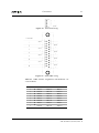
1
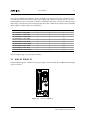
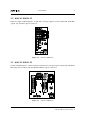
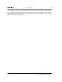
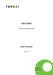
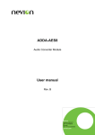
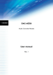
AAV-3G-XMUX
User Manual
Revision: B
2015-05-07
nevion.com
Contents
1
Revision History
3
2
Product Overview
4
2.1
4
3
Summary
Introduction
5
3.1
AAV-3G-XMUX-C1
6
3.2
AAV-3G-XMUX-C2
7
3.3
AAV-3G-XMUX-C3
7
4
Connections
9
5
Configuration
13
5.1
DIP switch configuration
13
5.2
GYDA configuration
13
6
General environmental requirements
14
A
Materials declaration and recycling information
15
A.1
Materials declaration
15
A.2
Recycling information
15
Revision History
3
1 Revision History
Revision
Date
Comments
A
2013-12-12
First revision
B
2015-05-07
Renumbered analogue connections.
AAV-3G-XMUX User Manual Rev. B
Product Overview
4
2 Product Overview
2.1 Summary
• Digital audio embedder with digital and analogue audio
• Less cabling on backpanels.
• High density: Single width backplane with two modules (Not original Flashlink frame or
N-box).
• Uses standard embedder and audio converter modules.
• 8 analogue audio signals and 4 AES signals.
• 3 audio converter module options
AAV-3G-XMUX User Manual Rev. B
Introduction
5
3 Introduction
The AAV-3G-XMUX is a integrated analog and digital audio embedding module in the Flashlink
range, offering simultaneous embedding and de-embedding of four AES3 stereo digital audio
channels and 4 analog stereo audio channels on a digital 3G/HD/SD-SDI serial video signal. The
product is a two card solution onto a backplane that can be a dual slot backplane for the Flashlink
frame, or a single slot backplane for the Flashcase or Flashlink II frame.
There are 4 AES ports and each may be used as either an input or an output. The sample rate converters may be inserted by the module when needed, or the user can disable them. data signals
such as Dolby-E will always be embedded transparently without using the sample rate converters.
There are three audio converter modules that may be used giving either A/D conversion , D/A
conversion or a combiation of both. The audio conversion is broadcast quality with more than
105dBA dynamic range for any conversion. All embedding and de-embedding is with synchronous 48 kHz audio.
The unit may be ordered with optical transmitter and receiver options. The laser options range
from the standard -5dBm 1310nm to the DWDM units.
The module has signal generators for audio and video for test and line-up applications. The internal video generator may be used as a fall-back source that is used if the both the electrical and
the optical input signals fail. This allows uninterrupted transmission of embedded audio.
The cards can be setup with DIP switches, web interface and SNMP. The audio control is provided
as a router level to the control system allowing for panel control. Signal status can be monitored
with the front LEDs, the web interface or with SNMP.
AAV-3G-XMUX User Manual Rev. B
Introduction
6
The AAV-3G-XMUX-Cn backplanes use two modules in a compact form factor. A number of cross
connections between the modules reduces the cabling and connector requirements of a system.
The backplanes may be used with a number of embedder and audio converter modules giving a
wide range of functionality. The following table shows the combinations which will work and the
audio signals available with each combination.
Module combinations
Analogue inputs
Analogue outputs
AES inputs and outputs
AV-3G-XMUX + ADC-AES8
8
0
4
AV-3G-XMUX + DAC-AES8
0
8
4
AV-3G-XMUX + ADDA-AES8
4
4
4
AV-HD-XMUX + ADC-AES8
4
0
2+2
AV-HD-XMUX + DAC-AES8
0
4
2+2
AV-HD-XMUX + ADDA-AES8
4
4
2+2
AV-SD-XMUX + ADC-AES8
4
0
2+2
AV-SD-XMUX + DAC-AES8
0
4
2+2
AV-SD-XMUX + ADDA-AES8
4
4
2+2
Three backplane types are presently available:-
3.1 AAV-3G-XMUX-C1
Single width backplane. 4 AES and 8 analogue signals on female d-sub DC-37, BNC SDI and single
optical connector.
Figure 3.1
AAV-3G-XMUX-C1
AAV-3G-XMUX User Manual Rev. B
Introduction
7
3.2 AAV-3G-XMUX-C2
Flashcase single width backplane. 4 AES and 8 analogue signals on Molex Male KK, SDTI BNC
output only and dual optical connectors.
Figure 3.2
AAV-3G-XMUX-C2
3.3 AAV-3G-XMUX-C3
Double width backplane. 5 AES on female d-sub DE-15, 8 analogue signals on female d-sub DB-25,
BNC SDI, 8P8C modular jack GPI/RS422 and dual optical connectors.
Figure 3.3
AAV-3G-XMUX-C3
AAV-3G-XMUX User Manual Rev. B
Introduction
8
The AV-HD-XMUX and AV-SD-XMUX modules may be used with thes backplanes but is only optimal with the ADDA-AES8. The other converter modules may be used but some of the analogue
audio channels will not be useable.
AAV-3G-XMUX User Manual Rev. B
Connections
9
4 Connections
The backplanes use the TASCAM standard pin assignment for 8 balanced audio channels on the
female DB-25. A similar pattern is used for the connections on the DE-15 and DC-37 dsub connectors as shown below. The numbering refers to the AES number on the XMUX embedder.
Figure 4.1
dsub DC37 wiring
Table 4.1a DC37 channel assignments with different converter modules
Channel.
ADC-AES8.
DAC-AES8.
ADDA-AES8.
1
AES1
AES1
AES1
2
AES2
AES2
AES2
3
AES5
AES5
AES5
4
AES6
AES6
AES6
5
ADC3 L
DAC3 L
DAC3 L
AAV-3G-XMUX User Manual Rev. B
Connections
10
Table 4.1b DC37 channel assignments with different converter modules
6
ADC3 R
DAC3 R
DAC3 R
7
ADC4 L
DAC4 L
DAC4 L
8
ADC4 R
DAC4 R
DAC4 R
9
ADC7 L
DAC7 L
ADC7 L
10
ADC7 R
DAC7 R
ADC7 R
11
ADC8 L
DAC8 L
ADC8 L
12
ADC8 R
DAC8 R
ADC8 R
Figure 4.2
dsub DE15 wiring
Table 4.2 DE15
channel assignments
Channel.
1
AES1
2
AES2
3
AES5
4
AES6
5
AES SYNC
The AES connections go to the XMUX embedder module. The AES SYNC connection is the ADC
AES11 sync input.
AAV-3G-XMUX User Manual Rev. B
Connections
11
Figure 4.3
Molex KK wiring
Figure 4.4
dsub DB25 wiring
Table 4.3 DB25 channel assignments with different converter modules
Channel.
ADC-AES8.
DAC-AES8.
ADDA-AES8.
1
ADC3 L
DAC3 L
DAC3 L
2
ADC3 R
DAC3 R
DAC3 R
3
ADC4 L
DAC4 L
DAC4 L
4
ADC4 R
DAC4 R
DAC4 R
5
ADC7 L
DAC7 L
ADC7 L
6
ADC7 R
DAC7 R
ADC7 R
7
ADC8 L
DAC8 L
ADC8 L
8
ADC8 R
DAC8 R
ADC8 R
AAV-3G-XMUX User Manual Rev. B
Connections
12
AV-HD-XMUX and AV-SD-XMUX cannot use ADC1 and ADC2 when used with an ADC-AES8.
AV-HD-XMUX and AV-SD-XMUX cannot use DAC3 and DAC4 when used with an DAC-AES8.
AV-HD-XMUX and AV-SD-XMUX signals AES1 and AES2 are outputs, and AES5 and AES6 are
inputs.
AAV-3G-XMUX User Manual Rev. B
Configuration
13
5 Configuration
5.1 DIP switch configuration
DIP switch configuration of the two modules in use will always work as described in the respective
module user manuals. It is up to the user to set the port directions of the AV-3G-XMUX correctly
according to the audio converter module in use. The AES ports on the embedder connected to the
audio converter modules are; AES3, AES4, AES7 and AES8. These signals are connected to the
AES1 to AES4 respective connections of the audio converter modules.
5.2 GYDA configuration
The dual slot backplane shows both modules as their normal types in the Flashlink chassis.
The single slot backplanes presently only show the embedder module. Future versions will also
show the converter module. The audio clipping levels of the audio converter modules must be
adjusted with the DIP switches if not shown on the web GUI.
The AV-3G-XMUX embedder module (Firmware FW 1.05 or higher) has a special control at the
bottom of the cofiguration page: Daughter converter board. The four options set the correct audio
ports to inputs or outputs and removes their configuration from the page. Changing the option
forces a reload of the card configuration so it will disappear shorlty from GYDA.
The options (other than none) change the main graphic on the info page which reflects the usage of
the audio ports (GYDA version 4.0.1 or higher). The numbering shown is chosen to be compatible
with the numbering in the audio matrix configuration. ADC and DAC signals shown are stereo
signals.
The AV-HD-XMUX and AV-SD-XMUX do not have configurable AES ports so the daughter converter board option is not present. AES3 and AES4 are outputs and will feed DAC1 and DAC2.
AES7 and AES8 are inputs and will receive the signal from ADC1 and ADC2 if the ADDA-AES8
is used. AES7 and AES8 are inputs and will receive the signal from ADC3 and ADC4 if the
ADC-AES8 is used.
AAV-3G-XMUX User Manual Rev. B
14
6 General environmental requirements
The equipment will meet the guaranteed performance specification under the following environmental conditions:
Operating room temperature range
Operating relative humidity range
0°C to 45°C
<90% (non-condensing)
The equipment will operate without damage under the following environmental conditions:
Temperature range
Relative humidity range
10°C to 55°C
<90% (non-condensing)
AAV-3G-XMUX User Manual Rev. B
Materials declaration and recycling information
15
Appendix A Materials declaration and recycling information
A.1 Materials declaration
For product sold into China after 1st March 2007, we comply with the “Administrative Measure
on the Control of Pollution by Electronic Information Products”. In the first stage of this legislation, content of six hazardous materials has to be declared. The table below shows the required
information.
This is indicated by the product marking:
A.2 Recycling information
Nevion provides assistance to customers and recyclers through our web site:
http://www.nevion.com/. Please contact Nevion’s Customer Support for assistance with
recycling if this site does not show the information you require.
Where it is not possible to return the product to Nevion or its agents for recycling, the following
general information may be of assistance:
Before attempting disassembly, ensure the product is completely disconnected from power and
AAV-3G-XMUX User Manual Rev. B
16
signal connections.
All major parts are marked or labeled to show their material content.
Depending on the date of manufacture, this product may contain lead in solder.
Some circuit boards may contain battery-backed memory devices.
AAV-3G-XMUX User Manual Rev. B