1
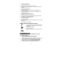
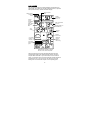
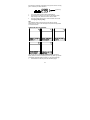
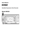
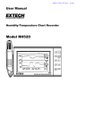
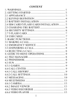
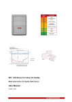
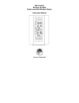
WS-9020U 915MHZ
INTELLIGENT WEATHER STATION
Instruction Manual
This product offers:
INSTANT TRANSMISSION is the stateof-the-art new wireless transmission
technology, exclusively designed and
developed by LA CROSSE
TECHNOLOGY. INSTANT
TRANSMISSION offers you an
immediate update (every 4 seconds!) of
all your outdoor data measured from
the sensors: Chart the weather as it
happens!
FEATURES
INTELLIGENT WEATHER STATION
Hanging hole
LCD
Display
Battery
compartment
Weather
information
text
Function Keys
•
•
•
Removable Stand
Immediate update (every 4 seconds!) of all your outdoor data
measured from the sensors (note: 4 second may vary while
updating)
WWVB Radio-controlled time with manual setting option
WWVB reception ON/OFF (user selectable)
1
•
•
•
•
•
•
•
•
•
•
•
•
•
•
•
•
•
12/24 hour time display
Time zone option ±12 hours
Calendar display (weekday, date, month, year)
Weather forecasting with 4 weather icons and weather tendency
indicator
Temperature display in °F/ºC
Humidity display as RH%
Indoor temperature and humidity display with MIN/MAX and
time/date of recording
Outdoor temperature and humidity display with MIN/MAX and
time/date of recording
Low/High outdoor temperature alarm
Relative air pressure unit in hPa or inHg
Air pressure tendency indicator for last 12h (bar graph format)
“Intelligent” weather information display
Can receive up to 3 remote sensors
LCD contrast selectable
Low battery indicator
Display in 5 languages selectable: English, German, French, Italian
and Spanish
Wall mounting or free standing
REMOTE TEMPERATURE/HUMIDITY SENSOR
•
•
•
•
Remote transmission of outdoor temperature and
humidity to the intelligent weather station by 915
MHz signal
Weather resistant casing
Wall mounting case
Mount in a sheltered place. Avoid direct rain and
sun.
QUICK SET-UP GUIDE
Hint: Use good quality Alkaline Batteries and avoid
rechargeable batteries.
1.
2.
3.
4.
Have the intelligent weather station and remote
temperature/humidity sensor 3 to 5 feet apart.
Batteries should be out of both the intelligent weather station and
remote temperature/humidity sensor units for 10 minutes.
Place the batteries into the remote temperature/humidity
sensor first and then into the intelligent weather station.
DO NOT PRESS ANY BUTTONS FOR 15 MINUTES.
2
In this time the intelligent weather station and remote
temperature/humidity sensor will begin to communicate with each other
and the display will show the temperature/humidity, outdoor
temperature/humidity. If the intelligent weather station does not display
all information after the 15 minutes, please retry the set up as stated
above. After all information has been displayed for 15 minutes you can
place your sensors outdoors and set your time.
Important Notes on Set-up and Operation
•
The remote temperature/humidity sensor should be placed in a
dry, shaded area.
•
Fog and mist will not harm your remote temperature/humidity
sensor but direct rain must be avoided.
•
The remote temperature sensor should be placed in a dry,
shaded area. The remote temperature sensor has a range of 330
feet. Keep in mind that the 330 feet is in open air with no
obstructions and that radio waves DO NOT curve around objects.
Actual transmission range will vary depending on what is in the
path of the signal. Each obstruction (roof, walls, floors, ceilings,
thick trees, etc.) will effectively cut signal range in half.
Example: A wireless weather station receiver with a 330 feet
range is mounted on an interior wall, so that the signal has to pass
through one interior wall, one exterior wall, and across the 10 foot
width of the room between the 2 walls. The first wall will reduce
the range to 165 feet, and the second wall will reduce the range to
87 feet. Factoring in the 10 foot room, this leaves a maximum of
77 feet of remaining signal range.
This allowance is typically enough for a frame wall with nonmetallic siding; however certain materials can reduce range even
further. Metal siding, stucco, and some types of glass can reduce
signal range by as much as ¾ or more, compared to the ½
reduction typical of most obstructions. It is possible to receive a
signal through these materials, however maximum range will be
much less due to their tendency to absorb or reflect a much larger
portion of the sensor’s signal.
•
The remote temperature/humidity sensor transmits a signal every
4 seconds – with variations during updating periods. After the
batteries have been installed, the intelligent weather station will
search for the signal for the duration of 45 seconds. If there is no
temperature or humidity reading in the OUTDOOR LCD after 5
minutes, make sure the units are within range of each other, or
repeat the battery installation procedure.
3
•
If a button is pressed before the intelligent weather station
receives the signal from the remote temperature/humidity sensor,
you will need to follow the battery installation procedure again.
To complete the set up of your new wireless intelligent weather station
after the 5 minutes have passed, please follow the steps in the “Manual
Settings” section.
Note:
If the outdoor sensor signal reception is not successful on the first
frequency of 915MHz for 45 seconds, the frequency is changed to
920MHz, and the learning is tried for another 45 seconds. If it is still not
successful the reception is tried for 45 seconds on 910MHz. This will
also be done during re-synchronization.
BATTERY INSTALLATION
INTELLIGENT WEATHER STATION
The intelligent weather station uses 3 x
AA (alkaline recommended) batteries.
When the batteries need to be
replaced the low battery symbol will
appear on the LCD (or replace the
batteries annually). To install and
replace the batteries, please follow the
steps below:
1.
Remove the cover.
2.
Insert batteries observing the
correct polarity (see battery
compartment marking).
3.
Replace battery cover.
REMOTE TEMPERATURE/HUMIDITY SENSOR
The remote temperature/humidity sensor uses 2 x AA
(alkaline recommended) batteries. To install and
replace the batteries, please follow the steps below:
1.
Remove the battery cover at the front side with a
small screwdriver.
2.
Insert the batteries, observing the correct polarity
(see battery compartment marking).
3.
Replace the battery cover on the unit.
Note:
When changing the batteries in any of the units, all units need to be
reset by following the “Quick Set Up Guide” procedures. This is because
4
a random security code is assigned by the sensor at start-up, and this
code must be received and stored by the intelligent weather station in
the first few minutes of power being supplied to it.
BATTERY CHANGE:
It is recommended to replace the batteries in all units on an annual
basis to ensure optimum accuracy of these units.
Please participate in the preservation of the environment.
Return used batteries to an authorized facility.
ABOUT WWVB (Radio Controlled Time)
The NIST (National Institute of Standards and Technology—Time and
Frequency Division) WWVB radio station is located in Ft. Collins,
Colorado, and transmits the exact time and date signal continuously
throughout the United States at 60 kHz. The signal can be received up
to 2,000 miles away through the internal antenna in the intelligent
weather station. However, due to the nature of the Earth’s Ionosphere,
reception is very limited during daylight hours. The intelligent weather
station will search for a signal every night when reception is best. The
WWVB radio station derives its signal from the NIST Atomic clock in
Boulder, Colorado. A team of atomic physicists is continually measuring
every second, of every day, to an accuracy of ten billionths of a second
per day. These physicists have created an international standard,
measuring a second as 9,192,631,770 vibrations of a Cesium-133 atom
in a vacuum. For more information on the atomic clock and WWVB
please see the NIST website at
http://www.boulder.nist.gov/timefreq/stations/wwvb.htm.
5
FUNCTION KEYS
Intelligent weather station:
The intelligent weather station has 5 easy to use function keys on the
right side of the unit.
SET key
CH key
MAX/+ key
MIN/- key
ALARM key
SET key
•
Press and hold the key to enter manual setting modes: LCD
contrast, 12/24 hour time display, time zone, daylight saving time
ON/OFF, manual time setting, calendar, WWVB ON/OFF, ºF/ºC
temperature unit, pressure unit, relative pressure setting and
language display
•
Confirm weather alarm in the setting mode
•
Reset individual MIN/MAX temperature/humidity record
•
Turn weather alarm off when sounding
!<deleted bullet>!
CH key (Channel key)
•
Select channel 1, 2, or 3 (if more than 1 sensor is used)
•
Exit setting mode
•
Detect/Re-detect sensor’s signal for all channels
•
Turn weather alarm off when sounding
6
MAX/+ key
•
Display MAX indoor / outdoor temperature and humidity records
with time of recording
•
Increase all values in manual setting modes
•
Increase the weather alarm values
•
Turn weather alarm off when sounding
•
Reset max/min record
MIN/- key
•
Display MIN indoor and outdoor temperature and humidity records
with time of recording
•
Decrease all values in manual setting modes
•
Decrease the weather alarm values
•
Turn weather alarm off when sounding
•
Reset max/min record
ALARM key
•
Enter the weather alarm time setting mode
•
Set next weather alarm in weather alarm setting mode
7
LCD SCREEN
The LCD screen is split into 6 sections displaying the information for
outdoor data, indoor data, time and date, weather forecast, air pressure
and air pressure history, weather information display.
Outdoor relative
humidity in
RH%
Signal reception
icon*
Outdoor
temperature
in °F or ºC
Outdoor
sensor
identification
number
Indoor Temperature
in °F or ºC
Indoor relative
humidity in
RH%
WWVB reception icon
(for WWVB time)
Time
display
Calendar
display
Weather
forecast icon
Air pressure
tendency
indicator
Relative air
pressure
display in
hPa or inHg
Air pressure
history bar
graph
Weather display information in English,
German, French, Italian and Spanish
*When the signal from the remote temperature/humidity sensor is
successfully received by the intelligent weather station, this signal
reception will be switched on. (If not successful, the icon will not be
shown on LCD) So the user can easily see whether the last reception is
successful (icon on) or not (icon off). On the other hand, the short
blinking of the icon shows that reception is currently taking place.
8
MANUAL SETTINGS
The following manual settings can be changed when pressing and
holding the SET key for approximately 4 seconds:
•
LCD contrast setting
•
12/24 hour time display
•
Time zone setting
•
Daylight time saving ON/OFF
•
Manual time setting
•
Calendar setting
•
WWVB time reception ON/OFF setting
•
°F/°C temperature unit setting
•
Air pressure unit setting
•
Relative pressure value setting
•
Language display setting
LCD CONTRAST SETTING
Last digit flashing
The LCD contrast can be set within 8 levels, from LCD 1 to LCD8
(default setting is LCD 5):
1.
Press and hold the SET key for about 4 seconds until the digit
start flashing.
2.
Use the MAX/+ or MIN/- key to view all levels of contrast.
3.
Select the desired LCD contrast. Press and release the SET key
to confirm selection and to enter the 12/24 Time Display setting.
12/24 HOUR TIME DISPLAY SETTING:
Digit flashing
The time display can be set to view time in 12 or 24 hour format. The
default time display mode is “12h”. To set to “24h” time display:
1.
Use the MAX/+ or MIN/- key to toggle the value.
2.
Press and release the SET key to confirm selection and to enter
the Time Zone setting.
TIME ZONE SETTING
Digit flashing
9
The time zone can be set ±12 hour. The default time zone is set to
Eastern Time zone (“EST”). To set a different time zone:
1.
The current time zone value starts flashing.
2.
Use the MAX/+ or MIN/- key to set the time zone. The MAX/+ key
increases the value and the MIN/- key decreases the value in
consecutive 1 hour intervals.
3.
Press and release the SET key to confirm selection and to enter
the Daylight saving time On/Off setting.
DAYLIGHT TIME SAVING ON/OFF SETTING
The Daylight Saving Time setting may be turned “on” or “off”.
Digit flashing
1.
2.
3.
The digit “ON” will start flashing on the LCD.Flashing
Use the MAX/+ or MIN/- key to turn OFF the daylight time saving
function.
Press and release the SET key to confirm selection and to enter
the Manual Time setting.
MANUAL TIME SETTING:
In case the intelligent weather station cannot detect the WWVB-signal
(for example due to disturbances, transmitting distance, etc.), the time
can be manually set. The clock will then work as a normal Quartz clock.
Minutes
flashing
Hour
flashing
1.
2.
3.
4.
5.
The hour digit will start flashing.
Use the MAX/+ or MIN/- key to set the hour.
Press again the SET key to switch to the minutes. The minute
digits start flashing.
Use the MAX/+ or MIN/- key to set the minutes.
Press and release the SET key to confirm selection and to enter
the Calendar setting.
Note:
The unit will still try to receive the WWVB signal between 0:00 and 6:00
am every day despite it being manually set, if the WWVB reception
function has been set ON. When it does receive the signal, it will change
10
the manually set time into the received time. During reception attempts
the WWVB tower icon will flash. If reception has been unsuccessful,
then the WWVB tower icon will not appear but reception will still be
attempted the following hour.
CALENDAR SETTING:
"Date. Month." (for 24h time display)
"Month. Date." (for 12h time display)
Weekday
Year
The date default of the intelligent weather station is 1. 1. in the year
2005. Once the radio-controlled time signals are received, the date is
automatically updated. However, if the signals are not received, the date
can also be set manually.
1.
The year starts flashing.
2.
Use the MAX/+ or MIN/- key to set the year. The range runs from
2005 to 2030.
3.
Press the SET key again to confirm and to enter the month
setting. The month starts flashing.
4.
Use the MAX/+ or MIN/- key to set the month.
5.
Press the SET key again to confirm and to enter the date setting
mode. The date starts flashing.
6.
Use the MAX/+ or MIN/- key to set the date.
7.
Press and release the SET key to confirm selection and to enter
the WWVB Time Reception ON/OFF setting.
WWVB TIME RECEPTION ON/OFF SETTING
Flashing
In area where reception of the WWVB time is not possible, the WWVB
time reception function can be turned OFF. The clock will then work as a
normal Quartz clock. (Default setting is ON).
4.
The digit “ON” will start flashing on the LCD.
5.
Use the MAX/+ or MIN/- key to turn OFF the time reception
function.
11
6.
Press and release the SET key to confirm selection and to enter
the ºF/ºC Temperature Unit setting.
Note:
If the WWVB time reception function is turned OFF manually, the clock
will not perform any reception of the WWVB time as long as the WWVB
OFF function is activated.
The WWVB reception icon
will not be displayed on the LCD.
°F/°C TEMPERATURE UNIT SETTING
Flashing
The temperature display can be selected to show temperature data in °F
or °C. (default °F)
1.
Use the MAX/+ or MIN/- key to toggle between “°F” or “°C”.
2.
Confirm with the SET key and enter the Air Pressure Unit
setting.
RELATIVE AIR PRESSURE UNIT SETTING
Flashing
The relative air pressure unit can be set in inHg or hPa unit. (default unit
is inHg).
1.
Use the MAX/+ or MIN/- key to toggle between “inHg”, “hPa” or
“mmHg”
2.
Press and release the SET key to confirm selection and to enter
the Relative Pressure Value setting.
Note:
The default reference pressure value of the barometer is 29.91 inHg
(1013 hPa). For an exact measurement it is necessary to first adjust
the barometer to your local relative air pressure (related to
elevation above sea level). Ask for the present atmospheric pressure
of your home area (Local weather service, calibrated instruments in
public buildings, airport).
RELATIVE PRESSURE VALUE SETTING
The default relative pressure value is 29.91 inHg (1013 hPa). This
corresponds to the average air pressure. Pressure below this is referred
to as low-pressure area (weather to become worse), pressure above as
high-pressure area (weather to improve). The relative air pressure can
12
be manually set to another value within the range of 28.35 to 30.72 inHg
(960 – 1040 hPa) for a better reference.
Digit flashing
1.
2.
3.
The current relative pressure value will start flashing
Use the MAX/+ or MIN/- key to increase or decrease the value.
Keep holding the key allows the value to advance faster.
Press and release the SET key to confirm selection and to enter
the Language display setting.
Note:
This calibration facility is useful for those users living at various
elevations above sea level, but wanting their air pressure display based
on sea level elevation.
LANGUAGE DISPLAY SETTING:
The language for the calendar and “Intelligent” weather information
display can be set to view in German (D), French (F), Italian (I), Spanish
(S) & English (E) Default setting is English. To set another language:
1.
Use the MAX/+ or MIN/- key to set the desired language.
13
2.
Press and release the SET key to confirm selection and exit the
Manual settings.
TO EXIT THE MANUAL SETTING MODE
To exit the manual setting anytime during the manual setting modes,
press the CH key anytime or wait for an automatic timeout. The mode
will return to normal time display.
OUTDOOR TEMPERATURE AND HUMIDITY:
The first LCD section can show the outdoor temperature, the reception
indicator, the minimum or maximum reading. A number in the bottom
part will also be shown if more than one sensor has been used.
Outdoor temperature
alarm icon
Outdoor temperature
in °F or °C
Outdoor humidity
display in RH%
MIN/MAX icon
Sensor identification number (only if there is
more than one sensor)
Outdoor reception signal
INDOOR RELATIVE HUMIDITY AND INDOOR
TEMPERATURE:
The indoor temperature and humidity data are automatically updated
and displayed in the second section of the LCD.
Indoor temperature
in °F or ºC
Indoor relative
humidity in %
TOGGLING BETWEEN MIN/MAX INDOOR AND OUTDOOR
RECORDINGS:
To toggle between the current, minimum and maximum data and the
times they were recorded, press the MIN/- key for viewing the minimum
values, and press the MAX/+ key for viewing the maximum values
(shown in MIN or Max displays).
When pressing the MIN/- or the MAX/+ key, the MIN and the MAX data
will be displayed as following sequences:
1.
MAX or MIN outdoor temperature data with time and date of
recordings. Data will flash
1.
MAX or MIN outdoor humidity data with time and date of
recordings. Data will flash
14
2.
3.
4.
MAX or MIN indoor temperature data with time and date of
recordings. Data will flash
MAX or MIN indoor humidity data with time and date of recordings.
Data will flash
Return to current indoor and outdoor data.
ADDING SENSORS (OPTIONAL)
The WS-9020U is able to receive signals from 3 remote
temperature/humidity sensors (TX28U-IT). These extra sensors can be
purchased through the same dealer as this unit
TO SET-UP OF MULTIPLE SENSORS
1.
2.
3.
4.
5.
6.
7.
Remove all the batteries from the receiver and sensor(s) and wait
60 seconds. During these 60 seconds, press any button 20 times
to discharge any excess power.
Insert the batteries to the first Thermo-hygro sensor.
Within 2 minutes of powering up the first sensor, insert the
batteries to the Weather Station. Once the batteries are in place,
all segments of the LCD will light up briefly. Following the
indoor/outdoor temperature and humidity, time as 12:00, calendar,
and weather icons will be displayed. If they are not shown in LCD
after 60 seconds, remove the batteries and wait for at least 60
seconds before reinserting them.
The outdoor temperature and humidity from the first sensor
(channel 1) should then be displayed on the Weather station. If
this does not happen and the signal reception icon is not shown,
after 2 minutes, the batteries will need to be removed from both
units and reset from step 1.
Insert the batteries to the second sensor as soon as the outdoor
temperature and humidity readings from the first sensor are
displayed on the Weather station.
NOTE: You must insert the batteries into the second sensor
within 45 seconds of reception of the first sensor.
The outdoor temperature and humidity from the second sensor
and the "channel 2" icon should then be displayed on the Weather
station. If this does not happen after 2 minute, the batteries will
need to be removed from all the units and reset from step 1.
Insert the batteries to the third sensor as soon as the "channel 2"
icon and outdoor data are displayed on the Weather station. Then
within 2 minutes, the channel 3 outdoor data from the third sensor
will be displayed and the channel icon will shift back to "1" once
the third sensor is successfully received. If this is not happen, user
shall restart the setting up from step 1.
NOTE: You must insert the batteries into the third sensor
within 45 seconds of reception of the second sensor.
15
IMPORTANT: Transmission problems will arise if the setting for
multiple sensors is not followed as described above. Should
transmission problems occur, it is necessary to remove the
batteries from all units and start again the set-up from step 1.
TO VIEW MIN/MAX INDOOR AND OUTDOOR RECORDS:
To toggle between the current, minimum and maximum data and the
times they were recorded, press the MIN/- key for viewing the minimum
values, and press the MAX/+ key for viewing the maximum values
(shown in MIN or Max displays).
Max icon
When pressing the MIN/- or the MAX/+ key, the MIN and the MAX data
will be displayed as following sequences:
1.
MAX or MIN outdoor temperature data with time and date of
recordings. Data will flash.
2.
MAX or MIN outdoor humidity data with time and date of
recordings. Data will flash.
3.
MAX or MIN indoor temperature data with time and date of
recordings. Data will flash.
4.
MAX or MIN indoor humidity data with time and date of
recordings. Data will flash.
5.
Return to current indoor and outdoor data.
TO VIEW THE MIN/MAX DATA FROM DIFFERENT
SENSORS
When more than 1 sensor used
1.
To toggle between sensors, press the CH key:
Once to show sensor 2
Twice to show sensor 3
Three times to return to sensor 1
2.
While the outdoor MIN/MAX humidity and temperature date is
being displayed, press the CH key. The display will toggle
between the different channels MIN/MAX data.
Note:
For example, when the MIN outdoor temperature data is displayed and
the MAX/+ key is pressed, MAX data outdoor temperature will be
16
displayed. If the MAX outdoor temperature data is displayed and the
MIN/- key is pressed, MIN outdoor data will be displayed.
While MIN/MAX data is displayed, the channel can be changed by
pressing the CH key.
TO RESET THE MIN/MAX VALUES TO CURRENT VALUES:
To reset individual indoor and outdoor MIN/MAX values to current
values:
1.
Press the MAX/+, MIN/- and CH key to select the desired
MIN/MAX value.
2.
Press the SET key to reset the selected value to current value
Note:
To reset all indoor and outdoor MIN/MAX values to current values, press
and hold the MAX/+ or MIN/- key for 3 seconds.
OUTDOOR CHANNEL RE-LEARN MODE
In case the temperature data in a particular outdoor channel often
shows “--.-“ due to low battery level or false reset of a sensor, that
sensor can be set up again.
To re-learn ALL channels:
Press and hold the CH key for 3 seconds (outdoor reception signal will
show next to channel display).
WEATHER ALARM SETTING
The intelligent weather station can be set to alert when a specific
weather condition is reach.
The following Weather Alarm settings can be changed when
pressing and holding the ALARM key for approximately 4 seconds:
•
LOW outdoor temperature alarm
•
HIGH outdoor temperature alarm
Default alarm values:
Temperature
alarm
Low
High
32ºF
86ºF
LOW OUTDOOR TEMPERATURE ALARM SETTING
Note:
The outdoor temperature alarm can only be set for channel 1 sensor.
17
To set the LOW outdoor temperature alarm (default OFF):
1.
Press and hold the ALARM key for about 3 seconds to enter the
alarm setting mode.
alarm icon
(low alarm)
alarm value
Weather alarm
indicator
The On/ Off
icon is flashing
2.
3.
4.
5.
Press the MAX/+ or MIN/- key to set the alarm ON or OFF.
Press the SET key to enter the alarm value setting (alarm value
flashing)
Use the MAX/+ or MIN/- key to set the alarm value.
Press the SET key to confirm and enter the HIGH outdoor
temperature alarm setting.
HIGH OUTDOOR TEMPERATURE ALARM SETTING
alarm icon
(high alarm)
alarm value
Weather alarm
indicator
The On/Off
icon is flashing
1.
2.
3.
4.
The On/ Off icon is flashing. Press the MAX/+ or MIN/- key to
activate the alarm ON/OFF.
Press the SET key to enter the alarm value setting (alarm value
flashing)
Use the MAX/+ or MIN/- key to set the alarm value.
Press the SET key to confirm and enter the HIGH outdoor
temperature alarm setting.
18
Note:
•
The outdoor temperature alarm is only applicable to Channel 1.
•
The alarm icon “
“ (outdoor high alarm) or “
“ (outdoor low
alarm) will be shown in normal display when the weather alarm is
set ON.
When the alarming outdoor temperature is reached, the alarm will sound.
The weather alarm indicator
, high or low alarm icon and the
temperature reading will be flashing on LCD. The alarm will sound for
120 seconds if no one stops the alarm. User may press any key to stop
the buzzer ringing. Then the weather alarm indicator, alarm icon and the
temperature reading will be still flashing but the sound is stopped.
If the alarm key is not pressed, the weather alarm indicator will keep
flashing, indicating that alarm temperature has been reached before.
User may press the Alarm key once to switch off the weather alarm
indicator.
WEATHER ALARM OPERATIONS
WEATHER ALARMS
The Weather alarms are selectable for when certain weather conditions
are met according to the user’s requirements. For example, the user can
set the thresholds for the outdoor temperature to +104°F (+40ºC) (high)
and +14ºF
(-10°C) (low), while only enabling the high alarm and disabling the low
alarm (i.e. temperatures < +14ºF (-10°C) won’t trigger alarm, but
temperatures > +104ºF (+40°C) will).
Alarm setting
Outdoor Temperature
Minimum
-40°F (40ºC)
Maximum
+139.8°F (59.9ºC)
HYSTERESIS
To compensate for fluctuation of the measured data, which may cause
the weather alarm to sound constantly if the measured reading is close
to user set level, a hysteresis function has been implemented for each
weather alarm. For example, if the high temperature alarm is set to
+77°F (+25°C) and the current value moves to +77°F (+25°C), the alarm
will be activated (if it has been enabled). Now when the temperature
drops to +76.8°F (+24.9°C) or below and thereafter again increases to
beyond +78°F (+25°C), the data will be blinking, but no alarm will be
activated. It has to drop to below +75.2°F (+24°C) (with a pre-set
hysteresis of 2ºF (1°C)) so that the alarm can be produced again.
Hysteresis values for the various weather data types are given in the
following table:
19
Weather data
Temperature
Humidity
Air pressure
Hysteresis
2°F
3% RH
0.03 inHg
WEATHER FORECAST AND WEATHER TENDENCY:
WEATHER FORECASTING ICONS:
There are 4 weather icons in the fourth section of LCD which can be
displayed in any of the following combinations:
Sunny
Cloudy with
sunny
intervals
Cloudy
Rainy
For every sudden or significant change in the air pressure, the weather
icons will update accordingly to represent the change in weather. If the
icons do not change, then it means either the air pressure has not
changed or the change has been too slow for the intelligent weather
station to register. However, if the icon displayed is a sun or rainy, there
will be no change of icon if the weather gets any better (with sunny icon)
or worse (with rainy icon) since the icons are already at their extremes.
The icons displayed forecasts the weather in terms of getting better or
worse and not necessarily sunny or rainy as each icon indicates. For
example, if the current weather is cloudy and the rainy icon is displayed,
it does not mean that the product is faulty because it is not raining. It
simply means that the air pressure has dropped and the weather is
expected to get worse but not necessarily rainy.
The change of weather forecast icon is in agreement with the
relationship between current relative pressure and the pressure change
in the last three hours.
If the weather is changing, both old weather icon and new weather icon
will be shown with a weather tendency indicator (animated arrows). If
the weather has not changed within 6 hours, only the new weather icon
in the middle display will be shown.
20
Examples of changing weather icons:
Note:
After initial set up of the intelligent weather station with the setting of the
relative value, readings for weather forecasts should be disregarded for
the next 12-24 hours. This will allow sufficient time for the intelligent
weather station to collect air pressure data at a constant altitude and
therefore result in a more accurate forecast.
If the intelligent weather station is moved to another location significantly
higher or lower than its initial standing point (for example from the
ground floor to the upper floors of a house), set again the relative air
pressure value, and discard the weather forecast for the next 12-24
hours. By doing this, the intelligent weather station will not mistake the
new location as being a possible change in air-pressure when really it is
due to the slight change of altitude.
AIR PRESSURE TENDENCY INDICATOR
The air pressure tendency indicators are located on the left side of the
air pressure display, below the weather icons, and they work
independently from the weather forecast icons. The air pressure
tendency indicator pointing upward or downward directions is displayed
based on comparing the difference of the air pressure recorded during a
full hour time frame.
Note:
•
An upward air pressure tendency indicator means that there is an
increase in air pressure within the past 4 hours.
•
A downward air pressure tendency indicator means that there is
an decrease in air pressure within the past 4 hours.
21
AIR PRESSURE
The fifth section of the LCD shows the relative air pressure and the air
pressure history.
Air pressure
changes in hPa
Air pressure over the last 12 hours
The reference relative air pressure can be set between 28.35 to 30.72
inHg (960 to 1040hPa). See “Relative pressure value setting” in
manual setting.
BAR GRAPH DISPLAY
You may select to display the history of the air pressure in the form of a
graph consisting of vertical bars on the intelligent weather station LCD.
AIR PRESSURE HISTORY
The bar graph of the electronic barometer shows the air pressure history
for the past 12 hours in 7 steps.
4.5hPa
3hPa
1.5hPa
0hPa
-1.5hPa
-3hPa
-4.5hPa
-12 h
-9h
-6h
-3h
-2h
-1h
0h
The horizontal axis represents the last 12 hours air pressure recordings
(-12, -6, -5, -4, -3, -2, -1, and 0 hour, from right to left). The bars are
plotted at each of the 7 steps and give the trend over the recorded
period. The scale on the right compares the result. The ″0″ in the middle
of this scale determines the current air pressure.
The vertical axis represents the air pressure changes in hPa (4.5, 3, 1.5,
“0” represents the current air pressure). Each change (±1.5, ±3, ±4.5;
the other values are not shown on the vertical axis but can be
determined) shows in inches of mercury (hPa), how high or low the past
air pressure was as compared to the current one. Rising bars indicate
the weather is getting better due to an increase in air pressure. A
downward sloping bars indicates a drop of the air pressure and the
weather is expected to get worse from the present time ″0″.
22
At every full hour the current air pressure is used as a basis for the
display of a new graph bar. The existing graph is then moved one bar to
the left.
Note:
For accurate barometric pressure trend, the intelligent weather station
should operate at the same altitude. For example, it should not be
moved from the ground to the second floor of the house. Should the unit
be moved to a new location, discard readings for the next 48 – 60 hours.
LOW BATTERY INDICATOR
The low battery indicator will be displayed in the LCD when the battery
power of the intelligent weather station is low. It is recommended to
replace the batteries in all units on an annual basis to ensure optimum
accuracy of the intelligent weather station.
Note: After battery change, both the intelligent weather station and the
sensor(s) need to be reset (see note ”Setting up”)
WEATHER INFORMATIONDISPLAY
The weather information display located at the last section of the LCD
will display the weather forecast based on data received from channel 1
and the air pressure.
The intelligent weather station will automatically display the following
information:
•
Maximum temperature of the day
•
Minimum temperature of the day
•
Probability of the weather forecast
•
Time frame for the weather forecast
•
Probability of snowfall
•
Probability of fog
•
Probability of glazed frost
•
Probability of tempest
•
Probability of strong wind
•
Probability of storm
•
Forecast for lowest night temperature
23
German
English
Italian
Spanish
French
DETAILED INFORMATION SHOWN IN THE WEATHER DISPLAY:
Timeframe for
weather
forecast
Probability of
weather
forecast
Maximum
temperature
of the day
Minimum
temperature
of the day
Probability of
snowfall
Probability of
fog
Probability of
glazed frost
English
Forecast
period
6 hours
12 hours
24 hours
36 hours
48 hours
Forecast
Index 65%
German
Vorhersageda
uer
6 Stunden
12 Stunden
24 Stunden
36 Stunden
48 Stunden
Prognose
Index 65%
Index 70%
Index 75%
Index 80%
Index 85%
MaxTemp
xx.xºF
Today xx :xx
MinTemp
xx.xºF
Today xx :xx
Snowfall
Index 65%
Index 75%
Index 70%
Index 75%
Index 80%
Index 85%
MaxTemp
xx.xºF
Heute xx :xx
MinTemp
xx.xºF
Heute xx :xx
Schnee
Index 65%
Index 75%
Fog
Index 80%
ndex 85%
Glazed frost
Index 75%
Nebel
Index 80%
Index 85%
Rauhreif
Index 75%
Language selected
French
Italian
Durata prev.
Period
6 ore
prevision
6 heures
12 heures
12 ore
24 heures
24 ore
36 heures
36 ore
48 heures
48 ore
Prévision
Indice
Index 65%
Previsione
65%
Indice 70%
Index 70%
Indice 75%
Index 75%
Indice 80%
Index 80%
Indice 85%
Index 85%
TempMax
MaxTemp
xx.xºF
xx.xºF
Du Jour xx :xx Oggi xx :xx
MinTemp
TempMin
xx.xºF
xx.xºF
Du Jour xx :xx Oggi xx :xx
Neige
Indice
Index 65%
Neve 65%
Index 75%
Neve 75%
Brouillard
Index 80%
Index 85%
Givre
Index 75%
24
Indice
Nebbia 80%
Indice 85%
Indice
Brina 75%
Spanish
Periodo prev.
6 horas
12 horas
24 horas
36 horas
46 horas
Indice
Prevision 65%
Indice 70%
Indice 75%
Indice 80%
Indice 85%
TempMax
xx.xºF
Hoy xx : xx
TempMin
xx.xºF
Hoy xx :xx
Indice
Nieve 65%
Nieve 75%
Indice
Niebla 80%
Indice 85%
Indice
Escarcha 75%
Probability of
tempest
Probability of
strong winds
Tempest
Index 80%
Strong wind
Index 80%
Gewitter
Index 80%
Starkwind
Index 80%
Orage
Index 80%
Vent Fort
Index 80%
Probability of
storm
Storm
Index 75%
Sturm
Index 75%
Tempête
Index 75%
Forecast
lowest night
temperature
Forecast
Min Erwartete
lowest
Nachttemp
Nighttemp xxºF xxºF
Prevision temp
Min nuit xxºF
Indice
Temporal 80%
Indice
Vento forte
80%
Indice
Tempesta 75%
Previsione
temp
Min notte xxºF
Indice
Tormenta 80%
Indice viento
Forte 80%
Indice
Tempestad
75%
Prevision temp
Min noche
xxºF
Note:
•
•
•
The forecast period, forecast index, and today’s
maximum/minimum temperature will always be shown on the
LCD.
The Forecast lowest night temperature will be displayed between
8:00 pm to 6:00 am
Other information will be show when a specific weather event
happened that has been calculated by the unique algorithm of the
intelligent weather station.
REMOTE TEMPERATURE/HUMIDITY SENSOR / 915MHZ
RECEPTION CHECK
The outdoor temperature and humidity is measured and transmitted
about every 4 seconds.
The transmission range of the remote temperature/humidity sensor may
be affected by the ambient temperature. At cold temperatures the
transmitting distance may be decreased. Please bear this in mind when
placing the sensor.
The remote temperature sensor should be placed in a dry, shaded area.
The remote temperature sensor has a range of 330 feet. Keep in mind
that the 330 feet is in open air with no obstructions and that radio waves
DO NOT curve around objects. Actual transmission range will vary
depending on what is in the path of the signal. Each obstruction (roof,
walls, floors, ceilings, thick trees, etc.) will effectively cut signal range in
half.
Example: A wireless weather station receiver with a 330 feet range is
mounted on an interior wall, so that the signal has to pass through one
interior wall, one exterior wall, and across the 10 foot width of the room
between the 2 walls. The first wall will reduce the range to 165 feet, and
the second wall will reduce the range to 87 feet. Factoring in the 10 foot
room, this leaves a maximum of 77 feet of remaining signal range.
25
This allowance is typically enough for a frame wall with non-metallic
siding; however certain materials can reduce range even further. Metal
siding, stucco, and some types of glass can reduce signal range by as
much as ¾ or more, compared to the ½ reduction typical of most
obstructions. It is possible to receive a signal through these materials,
however maximum range will be much less due to their tendency to
absorb or reflect a much larger portion of the sensor’s signal.
If the outdoor temperature and humidity data are not being received
within 2 minute after setting up (or the outdoor display show “--.-“ in the
outdoor section of the intelligent weather station after
failed attempts during normal operation). Please check the following
points:
1.
The distance of the intelligent weather station or remote
temperature/humidity sensor should be at least 3 to 6 feet (1.5 to
2 meters) away from any interfering sources such as computer
monitors or TV sets.
2.
Avoid positioning the intelligent weather station onto or in the
immediate proximity of metal doors or window frames.
3.
Using other electrical products such as headphones or speakers
operating on the same signal frequency (915MHz) may prevent
correct signal transmission and reception.
3.
Neighbors using electrical devices operating on the 915MHz
signal frequency can also cause interference.
4.
“Visibility” of the intelligent weather station and remote
temperature/humidity sensor (e.g. through a window) increases
the range.
Note:
When the 915MHz signal is received, do not re-open the battery cover
of either the remote temperature/humidity sensor or the intelligent
weather station, as the batteries may spring free from the contacts and
force a false reset. Should this happen accidentally then reset all units
(see Setting up above) otherwise transmission problems may occur.
If no reception is possible despite the observation of these factors, all
system units have to be reset (see Setting up).
POSITIONING THE INTELLIGENT WEATHER STATION:
The intelligent weather station has been designed to be hung on a wall
or free standing.
For Free standing:
Simply attached the stand to the bottom of the unit and
place onto a flat surface.
26
To wall mount
Choose a sheltered place. Avoid direct rain and sunshine.
Before wall mounting, please check that the outdoor temperature and
humidity values can be received from the desired locations.
To wall mount:
1.
Fix a screw (not supplied) into the desired wall,
leaving the head extended out the by about 0.2”
(5mm).
2.
Fold the stand of the intelligent weather station
by pushing inward and hang it onto the screw.
Remember to ensure that it locks into place
before releasing.
POSITIONING THE REMOTE
TEMPERATURE / HUMIDITY SENSOR:
The remote temperature/humidity sensor can be placed onto any flat
surface or wall mounted using the bracket which doubles as a stand or
wall mount base.
Table stand/wall
mount bracket
To wall mount:
1.
Secure the bracket onto a desired wall using the screws and
plastic anchors.
2.
Clip the remote temperature/humidity sensor onto the bracket.
Note:
Before permanently fixing the remote temperature/humidity sensor wall
base, place all units in the desired locations to check that the outdoor
temperature and humidity readings are receivable. In event that the
signal is not received, relocate the remote temperature/humidity sensor
or move them slightly as this may help the signal reception.
27
CARE AND MAINTENANCE
• Extreme temperatures, vibration and shock should be avoided as
these may cause damage to the units and give inaccurate forecasts
and readings.
• When cleaning the display and casings, use a soft damp cloth only.
Do not use solvents or scouring agents as they may mark the LCD
and casings.
• Do not submerge the units in water.
• Immediately remove all low powered batteries to avoid leakage and
damage. Replace only with new batteries of the recommended type.
• Do make any repair attempts to the units. Return it to their original
point of purchase for repair by a qualified engineer. Opening and
tampering with the units may invalidate their guarantee.
• Do not expose the units to extreme and sudden temperature
changes, this may lead to rapid changes in forecasts and readings
and thereby reduce their accuracy.
SPECIFICATIONS
Temperature measuring range:
Indoor
: +40°F to +139.8°F with Accuracy +/- 0.2°F resolution
-40ºC to +59.9ºC with Accuracy +/- 0.1ºC resolution
(“OF.L” displayed if outside this range)
Outdoor
: -39.8°F to +139.8°F with Accuracy +/- 0.2°F resolution
-39.9ºC to +59.9ºC with Accuracy +/- 0.1ºC resolution
(“OF.L” displayed if outside this range)
Relative humidity measuring range:
Indoor
:
1% to 99% with 1% resolution
(“- -” displayed when value < 1%; "99%"
displayed if value ≥ 99%)
Outdoor
:
1% to 99% with 1% resolution
(“1%” displayed when value ≤ 1%; "99%" is
played if value ≥ 99%)
Indoor temperature checking interval : every 20 seconds
Indoor humidity checking interval
: every 20 seconds
Outdoor temperature reception
: every 4 seconds
Outdoor humidity reception
: every 4 seconds
Sensor checking interval
: every 4 seconds
Air pressure checking interval
: every 20 seconds
Transmission range
: up to 300 feet (100 meters)
(open space)
Power supply:
Intelligent Weather Station
: 3 x AA batteries
Remote temperature/humidity sensor : 2 x AA batteries
28
Battery life cycle
: approximately 12 months
Alkaline batteries are recommended
Dimensions (H x L x W)
Intelligent Weather Station : 6.88” x 4.72” x 1.22” / 175 x 120 x 31
mm
Remote temperature/humidity sensor : 6.39” x 1.69” x 0.90” / 160 x 43
x 23mm
WARRANTY INFORMATION
La Crosse Technology, Ltd provides a 1-year limited warranty on this
product against manufacturing defects in materials and workmanship.
This limited warranty begins on the original date of purchase, is valid
only on products purchased and used in North America and only to the
original purchaser of this product. To receive warranty service, the
purchaser must contact La Crosse Technology, Ltd for problem
determination and service procedures. Warranty service can only be
performed by a La Crosse Technology, Ltd authorized service center.
The original dated bill of sale must be presented upon request as proof
of purchase to La Crosse Technology, Ltd or La Crosse Technology,
Ltd’s authorized service center.
La Crosse Technology, Ltd will repair or replace this product, at our
option and at no charge as stipulated herein, with new or reconditioned
parts or products if found to be defective during the limited warranty
period specified above. All replaced parts and products become the
property of La Crosse Technology, Ltd and must be returned to La
Crosse Technology, Ltd. Replacement parts and products assume the
remaining original warranty, or ninety (90) days, whichever is longer. La
Crosse Technology, Ltd will pay all expenses for labor and materials for
all repairs covered by this warranty. If necessary repairs are not
covered by this warranty, or if a product is examined which is not in
need or repair, you will be charged for the repairs or examination. The
owner must pay any shipping charges incurred in getting your La
Crosse Technology, Ltd product to a La Crosse Technology, Ltd
authorized service center. La Crosse Technology, Ltd will pay ground
return shipping charges to the owner of the product to a USA address
only.
Your La Crosse Technology, Ltd warranty covers all defects in material
and workmanship with the following specified exceptions: (1) damage
caused by accident, unreasonable use or neglect (including the lack of
reasonable and necessary maintenance); (2) damage occurring during
shipment (claims must be presented to the carrier); (3) damage to, or
deterioration of, any accessory or decorative surface; (4) damage
resulting from failure to follow instructions contained in your owner’s
manual; (5) damage resulting from the performance of repairs or
29
alterations by someone other than an authorized La Crosse Technology,
Ltd authorized service center; (6) units used for other than home use (7)
applications and uses that this product was not intended or (8) the
products inability to receive a signal due to any source of interference..
This warranty covers only actual defects within the product itself, and
does not cover the cost of installation or removal from a fixed
installation, normal set-up or adjustments, claims based on
misrepresentation by the seller or performance variations resulting from
installation-related circumstances.
LA CROSSE TECHNOLOGY, LTD WILL NOT ASSUME LIABILITY
FOR INCIDENTAL, CONSEQUENTIAL, PUNITIVE, OR OTHER
SIMILAR DAMAGES ASSOCIATED WITH THE OPERATION OR
MALFUNCTION OF THIS PRODUCT. THIS PRODUCT IS NOT TO BE
USED FOR MEDICAL PURPOSES OR FOR PUBLIC INFORMATION.
THIS PRODUCT IS NOT A TOY. KEEP OUT OF CHILDREN’S
REACH.
This warranty gives you specific legal rights. You may also have other
rights specific to your State. Some States do no allow the exclusion of
consequential or incidental damages therefore the above exclusion of
limitation may not apply to you.
For warranty work, technical support, or information contact:
La Crosse Technology, Ltd
2809 Losey Blvd. S.
La Crosse, WI 54601
Phone: 608.782.1610
Fax: 608.796.1020
e-mail:
[email protected]
(warranty work)
[email protected]
(information on other products)
web:
www.lacrossetechnology.com
Questions? Instructions? Please visit:
www.lacrossetechnology.com/9020
All rights reserved. This handbook must not be reproduced in any form,
even in excerpts, or duplicated or processed using electronic,
mechanical or chemical procedures without written permission of the
publisher.
30
This handbook may contain mistakes and printing errors. The
information in this handbook is regularly checked and corrections made
in the next issue. We accept no liability for technical mistakes or
printing errors, or their consequences.
All trademarks and patents are acknowledged.
FCC ID: OMO-TX28U (sensor)
FCC DISCLAIMER
RFExposure mobil:
The internal / external antennas used for this mobile sensor must provide a separation
distance of at least 20 cm (8 inches) from all persons and must not be co-located or
operating in conjunction with any other antenna or sensor."
Statement according to FCC part 15.19:
This device complies with Part 15 of the FCC Rules. Operation is subject to the following
two conditions: (1) this device may not cause harmful interference, and (2) this device must
accept any interference received, including interference that may cause undesired operation.
Statement according to FCC part 15.21:
Modifications not expressly approved by this company could void the user's authority to
operate the equipment.
Statement according to FCC part 15.105:
NOTE: This equipment has been tested and found to comply with the limits for a Class B
digital device, pursuant to Part 15 of the FCC Rules. These limits are designed to provide
reasonable protection against harmful interference in a residential installation. This
equipment generates, uses and can radiate radio frequency energy and, if not installed and
used in accordance with the instructions, may cause harmful interference to radio
communications.
However, there is no guarantee that interference will not occur in a particular installation. If
this equipment does cause harmful interference to radio or television reception, which can
be determined by turning the equipment off and on, the user is encouraged to try to correct
the interference by one or more of the following measures:
•
Reorient or relocate the receiving antenna.
•
Increase the separation between the equipment and receiver.
•
Connect the equipment into an outlet on a circuit different from that to which the
receiver is connected.
•
Consult the dealer or an experienced radio/TV technician for help
31