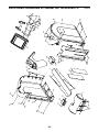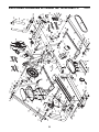
1
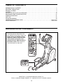
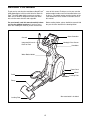
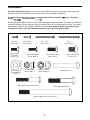
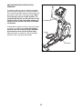
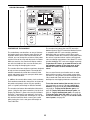
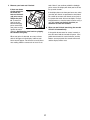
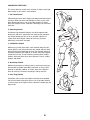
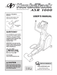
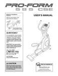
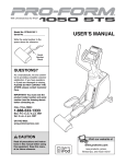
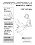
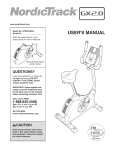
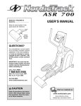
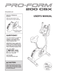
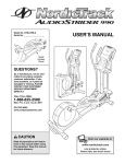
Model No. NTEL00907.0
Serial No.
Write the serial number in the
space above for reference.
USER’S MANUAL
Serial Number
Decal
QUESTIONS?
As a manufacturer, we are committed to providing complete customer
satisfaction. If you have questions,
or if parts are damaged or missing,
PLEASE DO NOT CONTACT THE
STORE; please contact
Customer Care.
IMPORTANT: You must note the
product model number and serial
number (see the drawing above)
before contacting us:
CALL TOLL-FREE:
1-888-825-2588
Mon.–Fri. 6 a.m.–6 p.m. MST
Sat. 8 a.m.–4 p.m. MST
ON THE WEB:
www.nordictrackservice.com
CAUTION
Read all precautions and instructions in this manual before using
this equipment. Keep this manual for future reference.
Visit our website at
www.nordictrack.com
new products, prizes,
fitness tips, and much more!
TABLE OF CONTENTS
WARNING DECAL PLACEMENT . . . . . . . . . . . . . . . . . . . . . . . . . . . . . . . . . . . . . . . . . . . . . . . . . . . . . . . . . . . . . .2
IMPORTANT PRECAUTIONS . . . . . . . . . . . . . . . . . . . . . . . . . . . . . . . . . . . . . . . . . . . . . . . . . . . . . . . . . . . . . . . .3
BEFORE YOU BEGIN . . . . . . . . . . . . . . . . . . . . . . . . . . . . . . . . . . . . . . . . . . . . . . . . . . . . . . . . . . . . . . . . . . . . . .4
ASSEMBLY . . . . . . . . . . . . . . . . . . . . . . . . . . . . . . . . . . . . . . . . . . . . . . . . . . . . . . . . . . . . . . . . . . . . . . . . . . . . . . .5
HOW TO USE THE ELLIPTICAL EXERCISER . . . . . . . . . . . . . . . . . . . . . . . . . . . . . . . . . . . . . . . . . . . . . . . . . .13
MAINTENANCE AND TROUBLESHOOTING . . . . . . . . . . . . . . . . . . . . . . . . . . . . . . . . . . . . . . . . . . . . . . . . . . .25
EXERCISE GUIDELINES . . . . . . . . . . . . . . . . . . . . . . . . . . . . . . . . . . . . . . . . . . . . . . . . . . . . . . . . . . . . . . . . . . .26
PART LIST . . . . . . . . . . . . . . . . . . . . . . . . . . . . . . . . . . . . . . . . . . . . . . . . . . . . . . . . . . . . . . . . . . . . . . . . . . . . . .28
EXPLODED DRAWING . . . . . . . . . . . . . . . . . . . . . . . . . . . . . . . . . . . . . . . . . . . . . . . . . . . . . . . . . . . . . . . . . . . .30
ORDERING REPLACEMENT PARTS . . . . . . . . . . . . . . . . . . . . . . . . . . . . . . . . . . . . . . . . . . . . . . . . . .Back Cover
LIMITED WARRANTY . . . . . . . . . . . . . . . . . . . . . . . . . . . . . . . . . . . . . . . . . . . . . . . . . . . . . . . . . . . . . .Back Cover
WARNING DECAL PLACEMENT
The warning decals shown here have
been applied in the locations shown. If a
decal is missing or illegible, call the
telephone number on the front cover
of this manual and request a free
replacement decal. Apply the decal in
the location shown. Note: The decal
may not be shown at actual size.
NordicTrack is a registered trademark of ICON IP, Inc.
iPod is a trademark of Apple Computer, Inc., registered in the U.S. and other countries.
2
IMPORTANT PRECAUTIONS
WARNING:
To reduce the risk of serious injury, read all important precautions and
instructions in this manual and all warnings on your elliptical exerciser before using your elliptical
exerciser. ICON assumes no responsibility for personal injury or property damage sustained by or
through the use of this product.
1. Before beginning any exercise program,
consult your physician. This is especially
important for persons over the age of 35 or
persons with pre-existing health problems.
8. Wear appropriate exercise clothes when
exercising; do not wear loose clothes that
could become caught on your elliptical exerciser. Always wear athletic shoes for foot
protection.
2. It is the responsibility of the owner to ensure
that all users of the elliptical exerciser are
adequately informed of all precautions.
9. Hold the handgrip pulse sensor or the handlebars when mounting, dismounting, or
using your elliptical exerciser.
3. Your elliptical exerciser is intended for home
use only. Do not use your elliptical exerciser
in a commercial, rental, or institutional setting.
10. Keep your back straight while using your
elliptical exerciser; do not arch your back.
11. The pulse sensor is not a medical device.
Various factors, including the user’s movement, may affect the accuracy of heart rate
readings. The pulse sensor is intended only
as an exercise aid in determining heart rate
trends in general.
4. Keep your elliptical exerciser indoors, away
from moisture and dust. Place your elliptical
exerciser on a level surface, with a mat
beneath it to protect the floor or carpet.
Make sure that there is enough clearance
around your elliptical exerciser to mount,
dismount, and use it.
12. When you stop exercising, allow the pedals
to slowly come to a stop.
5. Inspect and properly tighten all parts regularly. Replace any worn parts immediately.
13. If you feel pain or dizziness while exercising,
stop immediately and cool down.
6. Keep children under age 12 and pets away
from your elliptical exerciser at all times.
14. Use your elliptical exerciser only as
described in this manual.
7. Your elliptical exerciser should not be used
by persons weighing more than 300 lbs.
(136 kg).
3
BEFORE YOU BEGIN
Thank you for selecting the revolutionary NordicTrack®
ASR 1000 elliptical exerciser with Universal Dock for
iPod®. The ASR 1000 elliptical exerciser provides a
wide array of features designed to make your workouts at home more effective and enjoyable.
cover of this manual. To help us assist you, note the
product model number and serial number before contacting us. The model number and the location of the
serial number decal are shown on the front cover of
this manual.
For your benefit, read this manual carefully before
you use the elliptical exerciser. If you have questions after reading this manual, please see the front
Before reading further, please familiarize yourself with
the parts that are labeled in the drawing below.
Game Controller
Console
Handgrip Pulse Sensor
Integrated Universal
Dock for iPod
Handlebar
Water Bottle Holder*
Power Cord
Wheel
Pedal
Leveling Foot
Ramp
*No water bottle is included
Leveling Foot
4
ASSEMBLY
Assembly requires two persons. Place all parts of the elliptical exerciser in a cleared area and remove the
packing materials. Do not dispose of the packing materials until assembly is completed.
Assembly requires the included hex keys and your own Phillips screwdriver
wrench
, and rubber mallet
.
, adjustable
As you assemble the elliptical exerciser, use the drawings below to identify small parts. The number in parentheses
below each drawing is the key number of the part, from the PART LIST near the end of this manual. The number
following the parentheses is the quantity needed for assembly. Note: Some small parts may have been preassembled. If a part is not in the hardware kit, check to see if it has been preassembled.
#8 x .50"
Screw (92)–6
M6 x 14mm
Flat Head
Screw (75)–1
M10 x 22mm x
1.5mm Washer
(100)–2
#8 x 1.75"
Screw (95)–1
M4 x 16mm
Screw (90)–4
M8 x 19mm Patch
Screw (85)–4
M6 x 18mm Patch
Screw (108)–6
M8 Hex Nylon
Locknut (80)–4
#8 x 2"
Screw (74)–4
M10 Hex Nylon
Locknut (103)–4
M8 x 55mm Patch Screw (115)–4
M10 x 15mm Patch
Screw (77)–2
Barrel Nut (76)–1
M10 x 58mm Bolt (84)–4
M10 x 120mm Patch Screw (78)–2
5
1.
1
To make assembly easier, read the
information on page 5 before you begin
assembling the elliptical exerciser.
8
Remove the two M10 x 120mm Patch Screws
(78) and the shipping bracket (not shown)
attached to the front of the Frame (1). Discard
the shipping bracket. Do not discard the two
M10 x 120mm Patch Screws.
78
8
Orient the Front Stabilizer (49) with the Wheels
(8) in the position shown. While a second person tips the Frame (1) backward, attach the
Front Stabilizer to the Frame with the two M10 x
120mm Patch Screws (78).
49
1
2. Identify the Right Handlebar (36), which is
marked with an “R” sticker. While a second person holds the Right Handlebar near the Frame
(1), connect the Right Handlebar Wire (88) to
the Right Extension Wire (111). Insert the excess
wire into the Right Handlebar.
2
1
111
88
Attach the Right Handlebar (36) to the Frame (1)
with the Upper Body Endcap (34) and three
M6 x 18mm Patch Screws (108).
34
Repeat this step for the other side of the
elliptical exerciser.
36
108
6
3. Identify the Upright (3) and orient it as shown.
Then, pull the Pulse Wire (64) out of the top of
the Upright.
3
64
While a second person holds the Upright (3)
near the top of the Frame (1), slide the Upright
Cover (6) upward onto the Upright. Have the
second person hold the Upright Cover
around the Upright until step 5.
3
1
6
4. Note: For clarity, the Upright Cover (6) is not
shown in the drawing. Have the second person hold the Upright (3) and the Upright Cover
near the top of the Frame (1). Locate the wire
tie (see the inset drawing) in the Upright. Tie the
lower end of the wire tie to the Wire Harness
(46) and the Left and Right Extension Wires
(110, 111). Next, pull the upper end of the wire
tie upward out of the top of the Upright. Then,
untie and discard the wire tie. Tip: Do not allow
the ends of the wires to fall into the Upright.
Use a piece of tape or an elastic band to
hold the wires in place until step 6.
4
64
110
Wire Tie
111
46
110, 111
46
3
85
1
Slide the Upright (3) onto the Frame (1). Attach
the Upright with four M8 x 19mm Patch Screws
(85). Tip: Avoid pinching the Wire Harness
(46) and the Extension Wires (110, 111) during this step.
Avoid pinching
the wires during
this step
7
85
5. Slide the Upright Cover (6) downward to the
bottom of the Upright (3). Reattach the Upright
Cover with a #8 x 1.75" Screw (95).
5
3
95
6
6. While a second person holds the Console (4)
near the Upright (3), connect the console wire to
the Wire Harness (46). Next, connect the console pulse wire to the Pulse Wire (64). Then,
connect the game wire marked with an “R” tag
to the Right Extension Wire (111), which is also
marked with an “R” tag. Connect the other game
wire to the Left Extension Wire (110). Insert the
excess wire downward into the Upright.
6
Avoid pinching the
wires during this step
4
Game Wires
Pulse
Wire
Tip: Avoid pinching the wires during this
step. Attach the Console (4) to the Upright (3)
with four M4 x 16mm Screws (90).
Console
Wire
8
111
110
46 64
3
90
7. Identify and orient the Rear Stabilizer (2) as
shown. Tip: Remove the Ramp Cover (not
shown) and set it aside until step 11.
7
27
Lift the Ramp (55) and slide the Rear Stabilizer
(2) onto the Frame (1). Make sure to place the
Ramp on the indicated Rollers (27).
55
1
While a second person tips the Frame (1) forward, attach the Rear Stabilizer (2) with four
M10 x 58mm Bolts (84) and four M10 Hex Nylon
Locknuts (103). Tip: To prevent squeaking, do
not overtighten the Bolts.
84
84
103
2
8. Cut and remove the wire tie that holds the Link
Tube (30) inside the left Link Arm (25). Leave
the Link Tube inside the left Link Arm and then
position the Left Pedal Leg (24) and the left Link
Arm as shown.
8
25
Grease
30
76
Apply a small amount of the included grease to
a Barrel Nut (76). Insert the Barrel Nut through
the indicated holes in the Left Pedal Leg (24)
and the left Link Arm (25). Then, insert the
Barrel Nut through the Link Tube (30) inside the
left Link Arm.
24
Holes
Tighten an M6 x 14mm Flat Head Screw (75)
into the Barrel Nut (76).
9
75
9. Insert the axle of the Roller (27) through the
right Link Arm (25); make sure that the Roller
is on the inner side of the Link Arm. Attach
the Roller with an M10 x 15mm Patch Screw
(77) and an M10 x 22mm x 1.5mm Washer
(100). Tip: Use a wrench to hold the axle of
the Roller firmly in place while you tighten
the Patch Screw into the axle.
9
25
Repeat this step to attach the other Roller
(not shown) to the left Link Arm (25).
27
25
100 77
10. Orient a Pedal (26) as shown. Attach the Pedal
to the bracket on the Left Pedal Leg (24) with
two M8 x 55mm Patch Screws (115) and two
M8 Hex Nylon Locknuts (80).
10
26
Repeat this step to attach the other Pedal
(26).
115
24
80
26
10
11. Orient the Ramp Cover (7) as shown. Insert the
front edge of the Ramp Cover under the edge
of the Front Ramp Cover (66) and then press
the Ramp Cover onto the Ramp (55). Attach the
Ramp Cover with six #8 x .50" Screws (92).
11
7
92
92
92
66
55
12. Remove the shipping bracket (not shown)
inserted into the underside of the Frame (1).
Discard the shipping bracket.
12
While a second person tips the Frame (1) forward, tighten a Leveling Foot (9) into the underside of the Frame.
1
9
11
13. While a second person tips the elliptical exerciser forward, attach the Rear Stabilizer Cover (17)
to the Rear Stabilizer (2) with four #8 x 2"
Screws (74).
13
17
2
74
74
14. Make sure that all parts of the elliptical exerciser are properly tightened. Note: Some hardware may be
left over after assembly is completed. To protect the floor or carpet from damage, place a mat under the
elliptical exerciser.
Plug the power cord into the power socket at the front of the elliptical exerciser (see HOW TO PLUG IN THE
POWER CORD on page 13). IMPORTANT: If the elliptical exerciser has been exposed to cold temperatures, allow it to warm to room temperature before plugging in the power cord. If you do not do this,
the console displays or other electronic components may become damaged.
12
HOW TO USE THE ELLIPTICAL EXERCISER
HOW TO PLUG IN THE POWER CORD
HOW TO MOVE THE ELLIPTICAL EXERCISER
This product must be grounded. If it should malfunction or break down, grounding provides a path of
least resistance for electric current to reduce the risk
of electric shock. This product is equipped with a cord
having an equipment-grounding conductor and a
grounding plug. Plug the power cord into an appropriate outlet that is properly installed and grounded in accordance with all local codes and ordinances. This product is for use on a nominal 120volt circuit. IMPORTANT: The elliptical exerciser is
not compatible with GFCI-equipped outlets.
Due to the size and weight of the elliptical exerciser, moving it requires two persons. Stand in front of
the elliptical exerciser, hold the upright, and place one
foot against one of the front wheels. Pull on the
upright and have a second person lift the rear of the
track until the elliptical exerciser will roll on the front
wheels. Carefully move the elliptical exerciser to the
desired location, and then lower it to the floor.
DANGER:
Improper connection of
the equipment-grounding conductor can
result in an increased risk of electric shock.
Check with a qualified electrician or serviceman if you are in doubt as to whether the
product is properly grounded. Do not modify
the plug provided with the product—if it will
not fit the outlet, have a proper outlet
installed by a qualified electrician.
Pull on
upright
A temporary adapter may be used to connect the
power cord to a 2-pole receptacle as shown at the
right if a properly grounded outlet is not available. The
temporary adapter should be used only until a properly grounded outlet can be installed by a qualified electrician.
Place
your foot
here
Lift here
The greencolored rigid
Grounded Outlet Box
ear, lug, or
the like
Adapter
extending
from the
adapter must
be connected
Lug
to a permaMetal Screw
nent ground
such as a
properly
grounded outlet box cover. Whenever the adapter is
used, it must be held in place by a metal screw. Some
2-pole receptacle outlet box covers are not
grounded. Contact a qualified electrician to determine if the outlet box cover is grounded before
using an adapter.
HOW TO LEVEL THE ELLIPTICAL EXERCISER
If the elliptical
exerciser rocks
slightly on your
floor during
use, turn one or
both of the levLeveling
eling feet
Feet
beneath the
base or
beneath the
front stabilizer until the rocking motion is eliminated. If
the elliptical exerciser flexes during use, turn the leveling foot beneath the center of the frame.
13
HOW TO EXERCISE ON THE ELLIPTICAL
EXERCISER
To mount the elliptical exerciser, hold the handlebars
and step onto the pedal that is in the lower position.
Then, step onto the other pedal. Push the pedals until
they begin to move with a continuous motion. Note:
The crank arms can turn in either direction. It is
recommended that you turn the crank arms in the
direction shown by the arrow below; however, for
variety, you can turn the crank arms in the opposite direction.
Handlebars
To dismount the elliptical exerciser, wait until the pedals come to a complete stop. Note: The elliptical
exerciser does not have a free wheel; the pedals
will continue to move until the flywheel stops.
When the pedals are stationary, step off the higher
pedal first. Then, step off the lower pedal.
Pedals
Crank Arm
14
CONSOLE DIAGRAM
FEATURES OF THE CONSOLE
The console also features the new iFIT Interactive
Workout System. The iFIT Interactive Workout System
is compatible with iFIT cards containing workouts
designed to help you achieve specific fitness goals.
iFIT workouts control the resistance of the pedals while
the voice of a personal trainer coaches you and motivates you through your workout. One demo iFIT card is
included. Additional iFIT cards are available separately.
To purchase iFIT cards, go to www.iFIT.com or call
the telephone number on the front cover of this
manual. iFIT cards are also available at select
stores.
The revolutionary console offers an array of features
designed to make your workouts more effective and
enjoyable. When you use the manual mode of the
console, you can change the resistance of the pedals
and the incline of the ramp with the touch of a button.
While you exercise, the console will display continuous exercise feedback. You can also measure your
heart rate using the handgrip pulse sensor.
The console offers four weight loss workouts designed
to help you lose unwanted pounds. The weight loss
workouts automatically control the resistance of the
pedals and prompt you to vary your pace while counting the calories you burn.
You can even listen to your favorite music or audio
books with the console’s stereo sound system while
you exercise. This product has been designed specifically to work with iPod® and has been certified by the
developer to meet Apple performance standards.
In addition, the console offers twenty classic workouts.
Each workout automatically changes the resistance of
the pedals and prompts you to vary your pedaling
pace as it guides you through an effective workout.
To use the manual mode of the console, follow the
steps beginning on page 16. To use a weight loss
workout, see page 18. To use a classic workout,
see page 19. To play the Fat Blocker game, see
page 20. To play the Calorie Destroyer game, see
page 21. To play the Blackjack game, see page 22.
To play the Texas Hold ‘Em game, see page 23. To
use an iFIT workout, see page 24. To use the stereo
sound system, see page 24.
The console also features four motivational interactive
games. Using the dual game controllers, play the challenging Fat Blocker™ game or the fast-paced Calorie
Destroyer™ game during your workouts—the harder
you exercise, the greater your advantage! Or, use your
wits and the interactive touch screen to win credits
while playing the classic card game of Blackjack or
Texas Hold ‘Em.
15
HOW TO USE THE MANUAL MODE
Note: If there is a sheet of clear plastic on the face
of the console, remove the plastic.
1. Begin pedaling or press any button on the console to turn on the console.
A moment after you begin pedaling or press a button, the display will light.
2. Select the manual mode.
Each time you turn
on the console, the
manual mode will
be selected. If you
have selected a
workout, reselect
the manual mode
by pressing either of the Workouts buttons repeatedly until the word MANUAL appears in the lower
left corner of the display.
3.
The lower left corner of the display will show
the distance, in total revolutions, you have pedaled.
The upper right corner of the display will show
the approximate number of calories you have
burned. The upper right corner of the display will
also show your heart rate when you use the handgrip pulse sensor (see step 5 on page 17).
Begin pedaling and change the resistance of
the pedals and the incline of the ramp as
desired.
The lower right corner of the display will show
your pedaling pace in revolutions per minute
(rpm).
As you pedal,
change the resistance of the pedals by pressing
the Resistance
increase and
decrease buttons.
Note: After you press the buttons, it will take a
moment for the pedals to reach the selected
resistance level.
The center of the display will show the resistance level of the pedals for a few seconds each
time the resistance level changes. This display will
also show the ramp incline level for a few seconds
each time the ramp incline level changes.
You can also view selected information at a larger
size. Press the Display Mode button repeatedly to
view time and distance information, time and calorie information, or time and pace information.
Press the Display Mode button again to view all
information.
To vary the motion of the pedals, you can change
the incline of the ramp. To change the incline,
press the Ramp increase and decrease buttons.
Note: After you press the buttons, it will take a
moment for the ramp to reach the selected incline
level.
To adjust the volume level of the console, press
the increase and decrease buttons located next to
the Enter button.
4. Follow your progress with the display.
The console has two backlight options. The “On”
option keeps the backlight on while the console is
on. The “Off” option turns the backlight off. To
select a backlight option, first press and hold down
the Display Mode button for several seconds.
Next, press the increase button located next to the
Enter button to select the desired backlight option.
Then, press the Display Mode button to save your
selection.
The upper left corner of the display will show
the elapsed time. Note: When a workout is selected, the display will show the time remaining in the
workout instead of the elapsed time.
16
5. Measure your heart rate if desired.
onds. Note: If you continue to hold the handgrip
pulse sensor, the display will show your heart rate
for up to 30 seconds.
If there are sheets
of clear plastic on
Contacts
the metal contacts on the handgrip pulse sensor,
remove the plastic. To measure
your heart rate,
hold the handgrip
pulse sensor with
your palms resting
against the metal
contacts. Avoid moving your hands or gripping
the contacts too tightly.
If the display does not show your heart rate, make
sure that your hands are positioned as described.
Be careful not to move your hands excessively or
to squeeze the metal contacts too tightly. For optimal performance, clean the metal contacts using a
soft cloth; never use alcohol, abrasives, or
chemicals to clean the contacts.
6. When you are finished exercising, the console
will turn off automatically.
If the pedals do not move for several seconds, a
tone will sound and the console will pause. If the
pedals do not move for several minutes and the
buttons are not pressed, the console will turn off
and the display will be reset.
When your pulse is detected, one, two, or three
dashes will appear in the display, and then your
heart rate will appear. For the most accurate heart
rate reading, hold the contacts for at least 15 sec-
17
HOW TO USE A WEIGHT LOSS WORKOUT
As you exercise,
you will be prompted to keep your
pedaling pace near
the target rpm setting for the current
segment. When an
upward-pointing arrow appears in the display,
increase your pace. When a downward-pointing
arrow appears in the display, decrease your pace.
When no arrows appear, maintain your current
pace.
1. Begin pedaling or press any button on the console to turn on the console.
A moment after you begin pedaling or press a button, the display will light.
2. Select a weight loss workout.
To select one of the
Profile
four weight loss
workouts, press the
Weight Loss
Workouts button
repeatedly until the
name of the
desired workout
appears in the display. The workout time and a
profile of the resistance levels for the workout will
also appear in the display.
IMPORTANT: The target rpm settings are
intended only to provide motivation. Your actual pace may be slower than the target rpm settings. Make sure to pedal at a pace that is comfortable for you.
If the resistance level for the current segment is
too high or too low, you can manually override the
setting by pressing the Resistance buttons.
IMPORTANT: When the current segment of the
workout ends, the pedals will automatically
adjust to the resistance level programmed for
the next segment.
3. Begin pedaling or press the Start button to
start the workout.
Each workout is divided into several one-minute
segments. One resistance level and one target
rpm (pace) setting are programmed for each segment. Note: The same resistance and/or target rpm
setting may be programmed for consecutive segments.
The workout will continue in this way until the last
segment ends. To stop the workout at any time,
stop pedaling. A tone will sound and the time will
begin to flash in the display. To restart the workout,
simply resume pedaling.
The resistance level and the target rpm for the first
segment will appear in the center of the display for
a few seconds. During the workout, the workout
profile will show your progress (see the drawing
above). The flashing segment of the profile represents the current segment of the workout. The
height of the flashing segment indicates the resistance level for the current segment. At the end of
each segment of the workout, a series of tones will
sound and the next segment of the profile will
begin to flash. If a different resistance level and/or
target rpm is programmed for the next segment,
the resistance level and/or the target rpm will flash
in the display for a few seconds to alert you. The
resistance of the pedals will then change.
4. Follow your progress with the display.
See step 4 on page 16.
5. Measure your heart rate if desired.
See step 5 on page 17.
6. When you are finished exercising, the console
will turn off automatically.
See step 6 on page 17.
18
HOW TO USE A CLASSIC WORKOUT
As you exercise,
you will be prompted to keep your
pedaling pace near
the target rpm setting for the current
segment. When an
upward-pointing arrow appears in the display,
increase your pace. When a downward-pointing
arrow appears in the display, decrease your pace.
When no arrows appear, maintain your current
pace.
1. Begin pedaling or press any button on the console to turn on the console.
A moment after you begin pedaling or press a button, the display will light.
2. Select a classic workout.
To select one of the
Profile
twenty classic
workouts, press the
Classic Workouts
button repeatedly
until the name of
the desired workout
appears in the display. The workout time and a profile of the resistance levels for the workout will also appear in the
display.
IMPORTANT: The target rpm settings are
intended only to provide motivation. Your actual pace may be slower than the target rpm settings. Make sure to pedal at a pace that is comfortable for you.
If the resistance level for the current segment is
too high or too low, you can manually override the
setting by pressing the Resistance buttons.
IMPORTANT: When the current segment of the
workout ends, the pedals will automatically
adjust to the resistance level for the next segment.
3. Begin pedaling to start the workout.
Each workout is divided into 20, 30, or 45 oneminute segments. One resistance level and one
target rpm (pace) setting are programmed for each
segment. Note: The same resistance and/or target
rpm setting may be programmed for consecutive
segments.
The workout will continue in this way until the last
segment ends. To stop the workout at any time,
stop pedaling. A tone will sound and the time will
begin to flash in the display. To restart the workout,
simply resume pedaling.
The resistance level and the target rpm for the first
segment will appear in the center of the display for
a few seconds. During the workout, the workout
profile will show your progress (see the drawing
above). The flashing segment of the profile represents the current segment of the workout. The
height of the flashing segment indicates the resistance level for the current segment. At the end of
each segment of the workout, a series of tones will
sound and the next segment of the profile will
begin to flash. If a different resistance level and/or
target rpm is programmed for the next segment,
the resistance level and/or target rpm will flash in
the display for a few seconds to alert you. The
resistance of the pedals will then change.
4. Follow your progress with the display.
See step 4 on page 16.
5. Measure your heart rate if desired.
See step 5 on page 17.
6. When you are finished exercising, the console
will turn off automatically.
See step 6 on page 17.
19
HOW TO PLAY THE FAT BLOCKER GAME
Your goal is to
maneuver the
Complete Row
blocks so that they
form a complete
row of black
squares across the
entire arena. Each
time you complete a row of black squares, the row
will disappear, and all blocks above will move
downward one row.
The Fat Blocker game requires quick thinking and fast
reflexes. In addition to the console buttons, you will
use the four-button game controllers on the handlebars to play the game. Follow the steps below to play
the Fat Blocker game.
1. Begin pedaling or press any button on the console to turn on the console.
A moment after you begin pedaling or press a button, the display will light.
As you play, the blocks will fall faster and faster;
however, your pedaling pace will affect the speed
of the blocks—the faster you pedal, the more
slowly the blocks will fall, giving you extra time to
position and orient the blocks. The game will continue until any part of a stacked block reaches the
top of the arena.
2. Select the Fat Blocker game.
To select the Fat Blocker game, press the Fat
Blockers button. The words FAT BLOCKER will
appear at the top of the display.
When the game ends, the display will show your
final score and the level of play that you reached.
The display will then show the four highest scores
recorded since the scores were reset. If desired,
press and hold down the right button on either
controller to reset the scores.
3. Pedal to start the game.
When you start the Fat Blocker game, a game
arena will appear in the center of the display.
If your score is one of the four highest, the display
will prompt you to enter a name consisting of three
letters or digits. While the line below the first letter
is flashing, press the up and down buttons on
either controller to select the desired letter or digit.
Next, press the right button on either controller
and select another letter or digit. Repeat this
process to select a third letter or digit. Then, press
the right button on either controller again. The display will then show the four highest scores recorded since the scores were reset. Note: You can
also use the increase, decrease, and Enter buttons on the console to enter a high score name.
A block composed of four or five black squares will
slowly move downward until it reaches the bottom
of the arena. Another block will then move downward. There are blocks of eight different shapes.
As each block falls, you can move it to the left or
right using the left and right buttons on the left
controller. In addition, you can rotate the block
counterclockwise or clockwise using the left and
right buttons on the right controller. Once you have
positioned and oriented a block, you can speed its
motion to the bottom of the arena, if desired, by
pressing the down button on either controller.
4. Follow your progress with the display.
While you exercise and play the Fat Blocker game,
the corners of the display will show the elapsed
time, the approximate number of calories you have
burned, and your pedaling pace. In addition, the
display will show your current score and the game
level that you have reached.
To pause the game, press the Display Mode button. To resume the game, press the Display Mode
button repeatedly until the words FAT BLOCKER
appear at the top of the display, and then begin
pedaling.
5. When you are finished exercising, the console
will turn off automatically.
See step 6 on page 17.
20
Between the drones and the laser blaster are five
shields. You can hide the laser blaster below a
shield if desired. However, each time a shield is hit
by a laser, a piece will be vaporized.
HOW TO PLAY THE CALORIE DESTROYER GAME
The Calorie Destroyer game is a fast-paced game that
pits you against a squadron of laser-firing drones. In
addition to the console buttons, you will use the fourbutton game controllers on the handlebars to play the
game. Follow the steps below to play the Calorie
Destroyer game.
Your goal is to keep the laser blaster from being
hit and to keep any drone from reaching the bottom of the arena. If the laser blaster is hit, it will be
disabled and another laser blaster will appear in its
place; there are a total of four laser blasters. If you
vaporize the entire squadron of drones, a new
squadron will appear.
1. Begin pedaling or press any button on the console to turn on the console.
A moment after you begin pedaling or press a button, the display will light.
As you play, the drones will move faster and
faster. The game will continue until all four laser
blasters are disabled or a drone reaches the bottom of the arena.
2. Select the Calorie Destroyer game.
To select the Calorie Destroyer game, press the
Cal Destroyers button. The word DESTROYER
will appear at the top of the display.
When the game ends, the display will show the
level of play that you reached and your final score.
The display will then show the four highest scores
recorded since the scores were reset. If desired,
press and hold down the right button on either
controller to reset the scores.
3. Pedal to start the game.
When you start the Calorie Destroyer game, a
game arena will appear in the display. Three rows
of drones will begin to move across the top of the
arena, periodically firing their lasers downward.
Each time the drones reach the left or right side of
the arena, they will reverse direction and move
downward.
If your score is one of the four highest, the display
will prompt you to enter a name consisting of three
letters or digits. While the line below the first letter
is flashing, press the up and down buttons on
either controller to select the desired letter or digit.
Next, press the right button on either controller
and select another letter or digit. Repeat this
process to select a third letter or digit. Then, press
the right button on either controller again. The display will then show the four highest scores recorded since the scores were reset. Note: You can
also use the increase, decrease, and Enter buttons on the console to enter a high score name.
4. Follow your progress with the display.
While you exercise and play the Calorie Destroyer
game, the upper left corner of the display will show
the elapsed time. In addition, the display will show
the game level that you have reached and your
current score.
At the bottom of the arena is a laser blaster. You
can fire the laser blaster at the drones by pressing
the up button on either controller. In addition, while
you are pedaling, you can move the laser blaster
to the left or right using the left and right buttons
on either controller. The faster you pedal, the
faster the laser blaster will move.
To pause the game, press the Display Mode button. To resume the game, press the Display Mode
button repeatedly until the word DESTROYER
appears at the top of the display, and then begin
pedaling.
5. When you are finished exercising, the console
will turn off automatically.
See step 6 on page 17.
21
HOW TO PLAY THE BLACKJACK GAME
Blackjack is a casino-style card game in which you
compete against the dealer to win credits. Your goal
during each hand of the game is to have the highest
point total that does not exceed 21 points. You will use
the interactive touch screen on the display to play the
game. Follow the steps below to play Blackjack.
Note: For detailed instructions on how to play
Blackjack, consult a card game rule book or other
card game resource.
1. Begin pedaling or press any button on the console to turn on the console.
A moment after you begin pedaling or press a button, the display will light.
Count the point total of your cards and tap the
screen to select a game option. You can choose to
HIT, STAND, or DOUBLE. Repeat this action as
necessary until the hand ends.
2. Select the Blackjack game.
To select the Blackjack game, press the Black
Jack button. The word BLACKJACK will appear at
the top of the display.
When the hand ends, the result and the point
totals for you and the dealer will appear in a box
on the right side of the display. To continue the
game, tap the center of the screen.
3. Tap the screen to start the game.
The game will continue in this way indefinitely or
until you have no credits available to bet. If you
have no credits to bet, the words GAME OVER
and the game time will appear in the display. To
play Blackjack again, tap the prompt box on the
screen. To exit the game at any time, press the
Black Jack button.
As you pedal, tap the screen to begin the
Blackjack game. After a moment, the words
PLACE YOUR BET will appear in the display. Tap
the screen to select the amount you want to bet on
this hand. Note: You begin each game with 500
credits. As you win or lose credits during the
game, your current total will be shown in the upper
right corner of the display.
4. Follow your progress with the display.
After you place a bet, a representation of a game
table will appear in the display. The dealer’s cards
will appear in the upper left corner of the display.
Your cards will appear in the lower left corner of
the display. The game options will appear in three
boxes on the right side of the display.
While you pedal and play the Blackjack game, the
upper left corner of the display will show the
elapsed time. To view additional exercise information, press the Display Mode button repeatedly.
5. When you are finished exercising, the console
will turn off automatically.
See step 6 on page 17.
22
HOW TO PLAY THE TEXAS HOLD ‘EM GAME
When it is your turn, assess your cards and tap
the C/R/F game option box to make a betting decision; you can choose to CALL, RAISE, or FOLD.
You can also tap the CARDS box to view your
cards and any community cards on the table
before making a decision. Note: In some circumstances, you can choose to CHECK instead of
CALL.
Texas Hold ‘Em is a popular poker game in which you
compete against other players to win credits. Your
objective is to form the best five-card poker hand from
your two hole cards and the five community cards
shared by all the players. You will use the interactive
touch screen on the display to play the game. Follow
the steps below to play Texas Hold ‘Em.
Note: For detailed instructions on how to play
Texas Hold ‘Em, consult a card game rule book or
other card game resource.
If you decide to RAISE, tap the upward and downward arrow boxes to select the desired number of
credits, and then tap the OK box.
1. Begin pedaling or press any button on the console to turn on the console.
After you make your betting decision, play will continue with the other players. Continue to make betting decisions throughout the betting rounds and
the deals. When the flop is dealt, three cards will
appear in the upper left area of the display.
Additional cards will appear in this area when the
turn and river are dealt. Assess these cards and
make betting decisions as before. During the
game, the other players may fold, bust, or continue to a showdown.
A moment after you begin pedaling or press a button, the display will light.
2. Select the Texas Hold ‘Em game.
To select the Texas Hold ‘Em game, press the
Texas Hold’em button. The words TEXAS HOLD
‘EM will appear at the top of the display.
The player with the best five-card hand in any
combination of hole and community cards will win
the showdown.
3. Tap the screen to start the game.
As you pedal, tap the screen to begin the Texas
Hold ‘Em game. After you start the game, a representation of a game table will appear in the display. Your hole cards will be shown in the lower
left corner of the display. The number of credits in
the pot will be shown in the black box in the center
of the display. The amount bet by each player will
be shown along the right side of the display. A
game option box will be shown below the pot.
After the showdown, the word WINS: will appear in
the center of the display. The number of credits
won by each player will be shown along the right
side of the display. To view the cards held by the
other players, tap the number of credits won by
each player.
The game will continue in this way until you win all
the other players’ credits or until you have no credits available to bet. To exit the game at any time,
press the Texas Hold’em button.
4. Follow your progress with the display.
While you pedal and play the Texas Hold ‘Em
game, the upper left corner of the display will
show the elapsed time. To view additional exercise
information, press the Display Mode button repeatedly.
5. When you are finished exercising, the console
will turn off automatically.
See step 6 on page 17.
During the game, player information will appear
along the right side of the display. Your player
information is located in the lower right corner of
the display. The black X in the display indicates
the location of the dealer button. The black arrow
indicates which player’s turn it is.
23
HOW TO USE AN IFIT WORKOUT
HOW TO USE THE STEREO SOUND SYSTEM
1. Begin pedaling or press any button on the console to turn on the console.
To play music or audio books through the console’s
stereo sound system while you exercise, you must
connect your iPod®, CD player, or personal audio player through the audio jack or through the Integrated
Universal Dock for iPod®.
A moment after you begin pedaling or press a button, the display will light.
2. Insert an iFIT card and select a workout.
To use the audio jack, plug an audio cable (not included) into the jack on the console and into a jack on
your iPod, MP3 player, or CD player. Make sure that
the audio cable is fully plugged in.
To use an iFIT workout, insert an iFIT card into the
iFIT slot; make sure that the iFIT card is oriented
so the metal contacts are face down and are facing the slot. When the iFIT card is properly inserted, the indicator next to the slot will light and
words will appear in the display.
This product has been designed specifically to work
with iPod and has been certified by the developer to
meet Apple performance standards. To use the iFit®
Universal iPod® Connector, plug one end into the
Integrated Universal Dock for iPod and plug the other
end into your iPod. Make sure that the iFit Universal
iPod Connector is fully plugged in.
iFIT Slot
Next, press the play button on your iPod, MP3 player,
or CD player. Adjust the volume on your iPod, MP3
player, or CD player or press the Volume increase and
decrease buttons on the console.
iFIT Card
Next, select the desired workout on the iFIT card
by pressing the increase and decrease buttons
next to the iFIT slot.
A moment after you select a workout, the voice of
a personal trainer will begin guiding you through
your workout. iFIT workouts function in the same
way as classic workouts. To use the workout, see
steps 3 to 6 on page 19.
3. When you are finished exercising, remove the
iFIT card.
Remove the iFIT card when you are finished exercising. Store the iFIT card in a secure place.
24
MAINTENANCE AND TROUBLESHOOTING
Inspect and tighten all parts of the elliptical exerciser
regularly. Replace any worn parts immediately.
HOW TO LEVEL THE ELLIPTICAL EXERCISER
If the elliptical exerciser rocks slightly on your floor
during use, see HOW TO LEVEL THE ELLIPTICAL
EXERCISER on page 13.
To clean the elliptical exerciser, use a damp cloth and
a small amount of mild soap. IMPORTANT: To avoid
damage to the console, keep liquids away from
the console and keep the console out of direct
sunlight.
HANDGRIP PULSE SENSOR TROUBLESHOOTING
If the console does not display your heart rate when
you hold the handgrip pulse sensor, or if the displayed
heart rate appears to be too high or too low, see step
5 on page 17.
25
EXERCISE GUIDELINES
Burning Fat—To burn fat effectively, you must exercise at a low intensity level for a sustained period of
time. During the first few minutes of exercise, your
body uses carbohydrate calories for energy. Only after
the first few minutes of exercise does your body begin
to use stored fat calories for energy. If your goal is to
burn fat, adjust the intensity of your exercise until your
heart rate is near the lowest number in your training
zone. For maximum fat burning, exercise with your
heart rate near the middle number in your training
zone.
WARNING: Before beginning
this or any exercise program, consult your
physician. This is especially important for
persons over the age of 35 or persons with
pre-existing health problems.
The pulse sensor is not a medical device.
Various factors may affect the accuracy of
heart rate readings. The pulse sensor is
intended only as an exercise aid in determining heart rate trends in general.
Aerobic Exercise—If your goal is to strengthen your
cardiovascular system, you must perform aerobic
exercise, which is activity that requires large amounts
of oxygen for prolonged periods of time. For aerobic
exercise, adjust the intensity of your exercise until
your heart rate is near the highest number in your
training zone.
These guidelines will help you to plan your exercise
program. For detailed exercise information, obtain a
reputable book or consult your physician. Remember,
proper nutrition and adequate rest are essential for
successful results.
WORKOUT GUIDELINES
EXERCISE INTENSITY
Warming up—Start with 5 to 10 minutes of stretching
and light exercise. A warm-up increases your body
temperature, heart rate, and circulation in preparation
for exercise.
Whether your goal is to burn fat or to strengthen your
cardiovascular system, exercising at the proper intensity is the key to achieving results. You can use your
heart rate as a guide to find the proper intensity level.
The chart below shows recommended heart rates for
fat burning and aerobic exercise.
Training Zone Exercise—Exercise for 20 to 30 minutes with your heart rate in your training zone. (During
the first few weeks of your exercise program, do not
keep your heart rate in your training zone for longer
than 20 minutes.) Breathe regularly and deeply as you
exercise–never hold your breath.
Cooling down—Finish with 5 to 10 minutes of
stretching. Stretching increases the flexibility of your
muscles and helps to prevent post-exercise problems.
EXERCISE FREQUENCY
To find the proper intensity level, find your age at the
bottom of the chart (ages are rounded off to the nearest ten years). The three numbers listed above your
age define your “training zone.” The lowest number is
the heart rate for fat burning, the middle number is the
heart rate for maximum fat burning, and the highest
number is the heart rate for aerobic exercise.
To maintain or improve your condition, complete three
workouts each week, with at least one day of rest
between workouts. After a few months of regular exercise, you may complete up to five workouts each
week, if desired. Remember, the key to success is to
make exercise a regular and enjoyable part of your
everyday life.
26
SUGGESTED STRETCHES
The correct form for several basic stretches is shown at the right.
Move slowly as you stretch—never bounce.
1
1. Toe Touch Stretch
Stand with your knees bent slightly and slowly bend forward from
your hips. Allow your back and shoulders to relax as you reach
down toward your toes as far as possible. Hold for 15 counts,
then relax. Repeat 3 times. Stretches: Hamstrings, back of knees
and back.
2
2. Hamstring Stretch
Sit with one leg extended. Bring the sole of the opposite foot
toward you and rest it against the inner thigh of your extended
leg. Reach toward your toes as far as possible. Hold for 15
counts, then relax. Repeat 3 times for each leg. Stretches:
Hamstrings, lower back and groin.
3. Calf/Achilles Stretch
3
With one leg in front of the other, reach forward and place your
hands against a wall. Keep your back leg straight and your back
foot flat on the floor. Bend your front leg, lean forward and move
your hips toward the wall. Hold for 15 counts, then relax. Repeat
3 times for each leg. To cause further stretching of the achilles
tendons, bend your back leg as well. Stretches: Calves, achilles
tendons and ankles.
4
4. Quadriceps Stretch
With one hand against a wall for balance, reach back and grasp
one foot with your other hand. Bring your heel as close to your
buttocks as possible. Hold for 15 counts, then relax. Repeat 3
times for each leg. Stretches: Quadriceps and hip muscles.
5. Inner Thigh Stretch
5
Sit with the soles of your feet together and your knees outward.
Pull your feet toward your groin area as far as possible. Hold for
15 counts, then relax. Repeat 3 times. Stretches: Quadriceps and
hip muscles.
27
PART LIST—Model No. NTEL00907.0
Key No. Qty.
1
2
3
4
5
6
7
8
9
10
11
12
13
14
15
16
17
18
19
20
21
22
23
24
25
26
27
28
29
30
31
32
33
34
35
36
37
38
39
40
41
42
1
1
1
1
1
1
1
2
5
1
2
1
1
1
6
1
1
2
10
1
1
1
1
1
2
2
4
4
2
2
2
2
1
2
1
1
1
1
1
1
1
1
Description
Key No. Qty.
Frame
Rear Stabilizer
Upright
Console
Shield Cover
Upright Cover
Ramp Cover
Wheel
Leveling Foot
Eddy Mechanism
Pedal Leg Tube
Idler
Pulley
Crank
Crank Bearing
Resistance Motor
Rear Stabilizer Cover
Magnet
Pivot Bushing
Clamp
Reed Switch/Wire
Left Handlebar
Left Upper Body Arm
Left Pedal Leg
Link Arm
Pedal
Roller
Weld Spacer
Roller Axle
Link Tube
Crank Arm
Key
Left Side Shield
Upper Body Endcap
Rear Handle Cover
Right Handlebar
Right Upper Body Arm
Right Pedal Leg
Right Pedal Bracket
Right Side Shield
Pivot Axle
Crank Arm Spacer
43
44
45
46
47
48
49
50
51
52
53
54
55
56
57
58
59
60
61
62
63
64
65
66
67
68
69
70
71
72
73
74
75
76
77
78
79
80
81
82
83
84
28
1
2
2
1
1
1
1
2
1
1
1
1
1
1
1
1
1
1
1
2
1
2
2
1
1
1
5
4
2
2
2
4
2
2
2
2
1
5
20
2
2
4
R1007B
Description
Belt
Control Grip
Link Arm Endcap
Wire Harness
Power Harness
Left Pedal Bracket
Front Stabilizer
Stabilizer Endcap
Transformer
Control Board
Control Box
Control Box Cover
Ramp
Lift Bracket
Lift Motor
Tube Brace
Lift Axle
Pivot Pin
Hairpin
Roller Spacer
Ramp Axle
Pulse Grip/Wire
Cover Plate
Front Ramp Cover
Rear Ramp Cover
Power Receptacle
Custom Clip
Hood Clip
M6 x 9mm Patch Screw
M8 x 50mm Hex Screw
Large Snap Ring
#8 x 2" Screw
M6 x 14mm Flat Head Screw
Barrel Nut
M10 x 15mm Patch Screw
M10 x 120mm Patch Screw
M10 x 50mm Button Screw
M8 Hex Nylon Locknut
M6 x 12mm Patch Screw
M8 x 50mm Patch Screw
M8 x 16mm x 2mm Washer
M10 x 58mm Bolt
Key No. Qty.
85
86
87
88
89
90
91
92
93
94
95
96
97
98
99
100
101
4
16
1
1
2
4
6
14
2
3
1
2
5
6
4
2
6
Description
Key No. Qty.
M8 x 19mm Patch Screw
#8 x .75" Screw
Left Handlebar Wire
Right Handlebar Wire
Game Controller
M4 x 16mm Screw
M4 x 10mm Screw
#8 x .50" Screw
Small Snap Ring
M4 x 16mm T Screw
#8 x 1.75" Screw
M8 Nylon Locknut
#8 x .50" Cupped Screw
M10 x 29mm x 2mm Washer
Pedal Leg Bushing
M10 x 22mm x 1.5mm Washer
M10 x 20mm Patch Screw
102
103
104
105
106
107
108
109
110
111
112
113
114
115
*
*
*
2
7
2
2
1
2
6
4
1
1
2
1
1
4
–
–
–
Description
M10 x 89mm Hex Screw
M10 Hex Nylon Locknut
#8 x .313" Screw
M8 Hex Nylon Locknut Cls10.9
M8 x 78mm Patch Screw
Pedal Insert
M6 x 18mm Patch Screw
M6 Nylon Locknut
Left Extension Wire
Right Extension Wire
Ground Wire
Lift Motor Wire
Power Cord
M8 x 55mm Patch Screw
Hex Key
Grease Packet
User’s Manual
Note: Specifications are subject to change without notice. See the back cover of this manual for information about
ordering replacement parts. *These parts are not illustrated.
29
35
86
86
86
33
92
94
70
94
67
92
17
86
70
92
92
65
6
7
69 95
30
86
104
5
86
66
4
70
69
3
86
70
94
85
64
86
40
86
85
90
EXPLODED DRAWING A—Model No. NTEL00907.0
R1007B
101
45
31
98
108
75
26
80
92
44
63
34
9
62
57
93
91
15
115
62
74
19
27
61
106
101
81
15
9
98
101
55
2
80
13
42
103
84
24
39
107
110
1
9
81
112
15
87
81
97 20
18
28
99
14
19
111
81
18
41
103
84
11
71
105
31
103
72
114
102
81
28
19
32
19 23
101
98
56 59
98
60
101 79
98 19
81
107
30
48
29
27 103 58
22 27
108 83
89
77
100
76
25
73
26
21
97
97
98
115
75
38
100
77
30
54
31
102
72
37
9
11
8
76
25
96
99
47
49
36
113
28
99
32
71
105
82
16
101 92
19
50
53 103
68
15 28
19
12
10
51
27 29
45
93
80
19
88
109
96
15
92
9
34
92
73
91
91
50
52
8
82
108
15
91
44
112
78
43
46
92
89
EXPLODED DRAWING B—Model No. NTEL00907.0
R1007B
ORDERING REPLACEMENT PARTS
To order replacement parts, please see the front cover of this manual. To help us assist you, be prepared to
provide the following information when contacting us:
• the model number and serial number of the product (see the front cover of this manual)
• the name of the product (see the front cover of this manual)
• the key number and description of the replacement part(s) (see the PART LIST and the EXPLODED
DRAWING near the end of this manual)
LIMITED WARRANTY
ICON Health & Fitness, Inc. (ICON) warrants this product to be free from defects in workmanship and
material, under normal use and service conditions, for a period of one (1) year from the date of purchase.
There is a twelve (12) year warranty on the resistance mechanism. There is a lifetime warranty on the
frame. This warranty extends only to the original purchaser. ICON's obligation under this warranty is limited to replacing or repairing, at ICON's option, the product through one of its authorized service centers.
All repairs for which warranty claims are made must be pre-authorized by ICON. If the product is shipped
to a service center, freight charges to and from the service center will be the customer’s responsibility. For
in-home service, the customer will be responsible for a minimal trip charge. This warranty does not extend
to any product or damage to a product caused by or attributable to freight damage, abuse, misuse,
improper or abnormal usage or repairs not provided by an ICON authorized service center; products used
for commercial or rental purposes; or products used as store display models. No other warranty beyond
that specifically set forth above is authorized by ICON.
ICON is not responsible or liable for indirect, special or consequential damages arising out of or in connection with the use or performance of the product or damages with respect to any economic loss, loss
of property, loss of revenues or profits, loss of enjoyment or use, costs of removal or installation or other
consequential damages of whatsoever nature. Some states do not allow the exclusion or limitation of incidental or consequential damages. Accordingly, the above limitation may not apply to you.
The warranty extended hereunder is in lieu of any and all other warranties and any implied warranties of
merchantability or fitness for a particular purpose is limited in its scope and duration to the terms set forth
herein. Some states do not allow limitations on how long an implied warranty lasts. Accordingly, the above
limitation may not apply to you.
This warranty gives you specific legal rights. You may also have other rights which vary from state to state.
ICON HEALTH & FITNESS, INC., 1500 S. 1000 W., LOGAN, UT 84321-9813
Part No. 258568 R1007B
Printed in China © 2007 ICON IP, Inc.