1
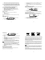
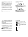
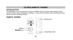
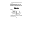
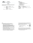
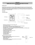
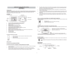
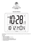
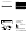
TABLE OF CONTENTS WIRELESS 915 MHz WEATHER STATION Instruction Manual Topic Inventory of Contents Features Setting Up Battery Installation Function keys LCD Screen and Settings Manual Settings Alarm setting and snooze Weather forecast icons and tendency Indoor temperature and MIN/MAX records Outdoor temperature and MIN/MAX records Resetting MIN/MAX records 915 MHz Reception Mounting Care and Maintenance Specifications Warranty Information Contents Language Pages English 1 French 22 Spanish 43 INVENTORY OF CONTENTS 1. Wireless Temperature Station 2. Wireless Temperature Sensor (TX37U-IT) and mounting bracket 3. Instruction Manual 1 This product offers: Page 2 3 4 5 6 8 9 11 11 14 14 14 15 16 17 18 19 2 INSTANT TRANSMISSION is the state-of-the-art new wireless transmission technology, exclusively designed and developed by LA CROSSE TECHNOLOGY. INSTANT TRANSMISSION offers you an immediate update (every 4 seconds!) of all your outdoor data measured from the transmitters: follow your climatic variations in real-time! Time display (hour and minutes) 12/24 hour display Alarm function with snooze Temperature display in degree Farenheit (ºF) or Celsius (°C) Indoor and outdoor temperature with MIN/MAX records Manual reset of MIN/MAX records Weather forecast with weather tendency indicator Wireless transmission at 915 MHz Signal reception intervals at 4 seconds Low battery indicator Wall mounting or table standing (foldout stand) The Outdoor Temperature Transmitter Remote transmission of outdoor temperature to Temperature Station by 915 MHz signals Rain resistant casing Wall mounting and table-standing FEATURES: The Weather station Hanging hole Battery compartment cover Battery compartment SETTING UP: Note: This weather station receives only one outdoor transmitter. 1. Function keys Foldout stand 3 2. First, insert the batteries into the Temperature transmitter. (see “Install and replace batteries in the Temperature transmitter“). Immediately after and within 30 seconds, insert the batteries into Weather station (see “Install and replace batteries in the Weather station”). Once the batteries are in place, all segments of the LCD will 4 3. 4. light up briefly. Following the time as 12:00 and the weather icon will be displayed. If these are not displayed after 60 seconds, remove the batteries and wait for at least 10 seconds before reinserting them. After inserting the batteries, the Weather station will start receiving data from the transmitter. The outdoor temperature and the signal reception icon should then be displayed on the Weather station. If this does not happen after 3 minutes, the batteries will need to be removed from both units and reset from step 1. In order to ensure sufficient 915 MHz transmission however, this should under good conditions be a distance no more than 100 meters (330 feet) between the final position of the Weather Station and the transmitter (see notes on “Mounting” and “915 MHz Reception”). HOW TO INSTALL AND REPLACE BATTERIES IN THE TEMPERATURE STATION The Weather Station uses 3 x AA, IEC LR6, 1.5V batteries. When batteries will need to be replaced, the low battery icon will appear on the LCD. To install and replace the batteries, please follow the steps below: 1. 2. 3. Lift up the battery compartment cover. Insert batteries observing the correct polarity (see marking). Replace compartment cover. HOW TO INSTALL AND REPLACE BATTERIES IN THE TEMPERATURE TRANSMITTER The Temperature Transmitter uses 2 x AA, IEC LR6, 1.5V battery. To install and replace the batteries, please follow the steps below: 1. 2. 3. Remove the battery compartment cover at the back of the transmitter. Insert the batteries, observing the correct polarity (see marking). Replace the battery compartment cover on the unit. Note: In the event of changing batteries in any of the units, all units need to be reset by following the setting up procedures. This is because a security code is assigned by the transmitter at start-up and this code must be received and stored by the Weather station in the first 3 minutes of power being supplied to it. BATTERY CHANGE: It is recommended to replace the batteries in all units regularly to ensure optimum accuracy of these units (Battery life See Specifications below). Please participate in the preservation of the environment. Return used batteries to an authorized depot. FUNCTION KEYS: Weather station: The weather station has four easy to use function keys. 5 6 LCD SCREEN AND SETTINGS: Time Alarm icon SET key + key ALARM key MIN/MAX RESET key SET key Press the key to enter manual setting modes: time, 12/24 hour time display, and temperature unit (ºC/ºF) setting Stop the alarm + key To make adjustment for various settings Stop the alarm ALARM key Enter the alarm setting mode Switch the alarm ON/ OFF Stop the alarm Weather forecast icon Weather tendency indicator Low battery indicator (transmitter) Outdoor Reception Signal icon* Low battery indicator (weather station) Outdoor Temperature in °C/ °F Indoor Temperature in °C/ °F MIN/MAX outdoor temperature MIN/MAX indoor temperature MIN/MAX RESET key Press and hold to reset the MIN/MAX temperature records Activate the snooze Exit manual setting modes * When the outdoor signal is successfully received by the Weather Station, this icon will be switched on. (If not successful, the icon will not be shown in LCD) So user can easily see whether the last reception was successful (icon on) or not (icon off). For a better display clarity, the LCD screen is split into 3 sections. Section 1 - TIME AND ALARM Display of time 7 8 Display the alarm icon will be shown when the alarm is turned on. Or when the snooze function is activated, the alarm icon will be flashing. Section 2 - WEATHER FORECAST AND WEATHER TENDENCY ICONS Display of the weather to be expected in form of three weather symbols and two weather tendency indicators in form of an arrow, which change their appearance depending on the air pressure development Section 3 – INDOOR AND OUTDOOR TEMPERATURE Display the current indoor temperature with MIN/MAX records Display of low battery indicator (weather station) Display the current outdoor temperature with MIN/MAX records A signal reception symbol will be shown indicating that receiver is receiving outdoor temperature Display of low battery indicator (transmitter) MANUAL SETTINGS: The following manual settings can be done in the setting mode: Time 12/24 time format Temperature unit setting 2. 3. 4. Use the + key to adjust the hours and then press SET key to go to the minute setting. The minute will be flashing. Press the + key to just the minutes. Confirm with the SET key and the enter the 12/24 hour time display setting 12/24 HOUR TIME DISPLAY SETTING The time can be set to display in 12h or 24h time format. Default setting 12h time format. To change the setting: Flashing 1. 2. 3. The current time format starts flashing Use the + key to select 12h or 24h time display. Confirm with the SET key and enter the Temperature unit setting. TEMPERATURE UNIT SETTING (ºF/ºC): The temperature unit can set to display temperature data in degree Fahrenheit (ºF) or Celsius (ºC); default setting is ºF. To change the setting: Press and hold the SET key for about 3 seconds to advance to the setting mode: MANUAL TIME SETTING To set the clock: Minutes (flashing) Hours (flashing) 1. Flashing 1. 2. 3. The current temperature value starts flashing. Use the + key to change the unit. Confirm with the SET key and exit the setting mode. The hour digits start flashing in the time display section. 9 10 ALARM SETTING Alarm time Alarm icon (ON) To set alarm: 1. Press and hold ALARM for about 3 seconds until the alarm time display flashes. 2. The hour digit and the alarm icon will be flashing. Press the + key to adjust the hour. 3. Press ALARM button once and minute digit will be flashing. User shall then press + button to set the minute. 4. Press ALARM button once to confirm the setting. 5. To activate/ deactivate the alarm function, press the ALARM button once. The display of the alarm icon represents that the alarm is "ON". Note: The duration of alarm sounding is 85 seconds TO ACTIVATE THE SNOOZE FUNCTION AND STOPPING THE ALARM: 1. When the alarm is sounding, press the MIN/MAX RESET key to activate the snooze function. The alarm will stop and re-activate after the snooze interval of 10 minutes. 2. To stop the alarm completely, press any keys other than the MIN/MAX RESET key. WEATHER FORECAST AND TENDENCY THE WEATHER FORECASTING ICONS : There are 3 weather icons in the second section of LCD which can be displayed in any of the following combinations : 11 Sunny Cloudy with sunny intervals Rainy For every sudden or significant change in the air pressure, the weather icons will update accordingly to represent the change in weather. If the icons do not change, then it means either the air pressure has not changed or the change has been too slow for the Weather station to register. However, if the icon displayed is a sun or raining cloud, there will be no change of icon if the weather gets any better (with sunny icon) or worse (with rainy icon) since the icons are already at their extremes. The icons display weather forecasts in terms of getting better or worse, and not necessarily sunny or rainy as each icon indicates. For example, if the current weather is cloudy and the rainy icon is displayed, it does not mean that the product is faulty because it is not raining. It simply means that the air pressure has dropped and the weather is expected to get worse but not necessarily rainy. Note : After setting up, readings for weather forecasts should be disregarded for the next 48-60 hours. This will allow sufficient time for the Weather Station to collect air pressure data at a constant altitude and therefore result in a more accurate forecast. Common to weather forecasting, absolute accuracy cannot be guaranteed. The weather forecasting feature is estimated to have an accuracy level of about 75% due to the varying areas the Weather Station has been designed 12 for use in. In areas that experience sudden changes in weather (for example from sunny to rain), the Weather Station will be more accurate compared to use in areas where the weather is stagnant most of the time (for example mostly sunny). If the Weather Station is moved to another location significantly higher or lower than its initial standing point (for example from the ground floor to the upper floors of a house), remove the batteries and re-insert them after about 30 seconds. By doing this, the Weather Station will not mistake the new location as being a possible change in air-pressure when really it is due to the slight change of altitude. Again, disregard weather forecasts for the next 4860 hours as this will allow time for operation at a constant altitude. THE WEATHER TENDENCY INDICATOR Working together with the weather icons are the weather tendency indicators (located on the left and right hand side of the weather icons). When the indicator points upwards, it means that the air-pressure is increasing and the weather is expected to improve, but when indicator points downwards, the air-pressure is dropping and the weather is expected to become worse. Taking this into account, you will see how the weather has changed and how it is expected to change. For example, if the indicator is pointing downwards together with cloud and sun icons, then the last noticeable change in the weather was when it was sunny (sun icon only). Therefore, the next change in the weather will be the cloud with rain icons since the indicator is pointing downwards. Note : Once the weather tendency indicator has registered a change in the air pressure, it will remain permanently visualized on the LCD. INDOOR TEMPERATURE AND MIN/MAX RECORDS The indoor temperature and indoor MIN/MAX records are displayed on the last section of the LCD. Indoor icon Indoor Temperature MAX record Note: The MIN/MAX indoor temperature range is 15ºF to 99ºF with 1ºF resolution (-9ºC to + 38ºC with 1°C resolution). OUTDOOR TEMPERATURE AND MIN/MAX RECORDS The outdoor temperature and outdoor MIN/MAX records are displayed on the last section of the LCD. Outdoor icon In normal display mode, press and hold the MIN/MAX RESET key for 3 seconds. This will reset the indoor and outdoor MIN/MAX temperatures. LOW BATTERY INDICATOR Low battery indicator is displayed on the LCD when the batteries require changing. 915 MHz RECEPTION CHECK The Weather station should receive the temperature data within 3 minutes after set-up. If the temperature data is not received 3 minutes after setting up (not successfully continuously, the outdoor display shows “- - -” ), please check the following points: 1. The distance of the Weather station or transmitter should be at least 1.5 to 2 meters (5 to 6.5 feet) away from any interfering sources such as computer monitors or TV sets. 2. Avoid positioning the Weather station onto or in the immediate proximity of metal window frames. 3. Using other electrical products such as headphones or speakers operating on the same signal frequency (915MHz) may prevent correct signal transmission and reception. 4. Neighbors using electrical devices operating on the 915MHz signal frequency can also cause interference. Note: When the 915MHz signal is received correctly, do not re-open the battery cover of either the transmitter or Weather station, as the batteries may spring free from the contacts and force a false reset. Should this happen accidentally then reset all units (see Setting up above) otherwise transmission problems may occur. The transmission range is about 100 m from the transmitter to the Weather station (in open space). However, this depends on the surrounding environment and interference levels. If no 15 Outdoor reception signal icon Outdoor Temperature MAX record MIN record Note: The MIN/MAX outdoor temperature resolution range is -40ºF to 140ºF with 1ºF resolution (-40ºC to + 60ºC with 1°C resolution). RESETTING THE INDOOR AND OUTDDOR MIN/MAX RECORDS Note: All the MIN/MAX records will be reset at the same time. 13 1. MIN record 14 reception is possible despite the observation of these factors, all system units have to be reset (see Setting up). POSITIONING THE TEMPERATURE STATION: The Weather Station may be hung onto wall easily or free standing. To wall mount Choose a sheltered place. Avoid direct rain and sunshine. Before wall mounting, please check that the outdoor temperature values can be received from the desired locations. 1. 2. Fix a screw (not supplied) into the desired wall, leaving the head extended out the by about 5mm. Fold the stand and hang the station onto the screw. Remember to ensure that it locks into place before releasing. Free standing With the foldout stand, the weather station can be placed onto any flat surface. 16 POSITIONING THE TEMPERATURE TRANSMITTER: The Transmitter is supplied with a holder that may be attached to a wall with the two screws supplied. The Transmitter can also be position on a flat surface by securing the stand to the bottom to the Transmitter. To wall mount: 1. Secure the bracket onto a desired wall using the screws and plastic anchors. 2. Clip the remote temperature sensor onto the bracket. Note: Before permanently fixing the transmitter wall base, place all units in the desired locations to check that the outdoor temperature reading is receivable. In event that the signal is not received, relocate the transmitters or move them slightly as this may help the signal reception. CARE AND MAINTENANCE: Extreme temperatures, vibration and shock should be avoided as these may cause damage to the unit and give inaccurate forecasts and readings. Precautions shall be taken when handling the batteries. Injuries, burns, or property damage may be resulted if the batteries are in contact with conducting materials, heat, corrosive materials or explosives. The 17 Indoor temperature checking interval : every 16 seconds Outdoor data reception : every 4 seconds Power consumption: Weather station : 3 x AA, IEC, LR6, 1.5V Temperature transmitter : 2 x AA, IEC, LR6, 1.5V Battery life cycle (Alkaline batteries recommended) : Appr. 24 months Dimensions (L x W x H) : Weather station : 5.33” x 1.10” x 5.56” / 135.4 x 28 x 141.4mm Temperature transmitter : 1.50” x 0.83” x 5.05” / 38.2 x 21.2 x 128.3mm WARRANTY La Crosse Technology, Ltd provides a 1-year limited warranty on this product against manufacturing defects in materials and workmanship. This limited warranty begins on the original date of purchase, is valid only on products purchased and used in North America and only to the original purchaser of this product. To receive warranty service, the purchaser must contact La Crosse Technology, Ltd for problem determination and service procedures. Warranty service can only be performed by a La Crosse Technology, Ltd authorized service center. The original dated bill of sale must be presented upon request as proof of purchase to La Crosse Technology, Ltd or La Crosse Technology, Ltd’s authorized service center. La Crosse Technology, Ltd will repair or replace this product, at our option and at no charge as stipulated herein, with new or reconditioned parts or products if found to be defective during the limited warranty period specified above. All replaced parts and products become the property of La Crosse Technology, Ltd and must be returned to La Crosse Technology, Ltd. Replacement parts and products assume the remaining original warranty, or ninety (90) days, whichever is longer. La Crosse Technology, Ltd will pay all expenses for labor and materials for all repairs covered by this warranty. If necessary repairs are not covered by this warranty, or if a product is 19 batteries shall be taken out from the unit before the product is to be stored for a long period of time. Immediately remove all low powered batteries to avoid leakage and damage. Replace only with new batteries of the recommended type. When cleaning the display and casings, use a soft damp cloth only. Do not use solvents or scouring agents as they may mark the LCD and casings. Do not submerge the unit in water. Special care shall be taken when handling a damaged LCD display. The liquid crystals can be harmful to user's health. Do not make any repair attempts to the unit. Return them to their original point of purchase for repair by a qualified engineer. Opening and tampering with the unit may invalidate their guarantee. Never touch the exposed electronic circuit of the device as there is a danger of electric shock should it become exposed. Do not expose the units to extreme and sudden temperature changes, this may lead to rapid changes in forecasts and readings and thereby reduce their accuracy. SPECIFICATIONS: Recommended operating temperature range: 32ºF to 122ºF / 0ºC to 50ºC Temperature measuring range: Indoor : 14.2ºF to +99.9ºF with 0,2ºF resolution -9.9ºC to +37.8ºC with 0.1ºC resolution (*Note: the max. indoor temperature measuring range in degree Fahrenheit is less than in degree Celsius) (“OF.L” displayed if outside this range) Outdoor : -39.8°F to +139.8°F with 0.2°F resolution -39.9ºC to +59.9ºC with 0.1ºC resolution (“OF.L” displayed if outside this range) 18 examined which is not in need or repair, you will be charged for the repairs or examination. The owner must pay any shipping charges incurred in getting your La Crosse Technology, Ltd product to a La Crosse Technology, Ltd authorized service center. La Crosse Technology, Ltd will pay ground return shipping charges to the owner of the product to a USA address only. Your La Crosse Technology, Ltd warranty covers all defects in material and workmanship with the following specified exceptions: (1) damage caused by accident, unreasonable use or neglect (including the lack of reasonable and necessary maintenance); (2) damage occurring during shipment (claims must be presented to the carrier); (3) damage to, or deterioration of, any accessory or decorative surface; (4) damage resulting from failure to follow instructions contained in your owner’s manual; (5) damage resulting from the performance of repairs or alterations by someone other than an authorized La Crosse Technology, Ltd authorized service center; (6) units used for other than home use (7) applications and uses that this product was not intended or (8) the products inability to receive a signal due to any source of interference. This warranty covers only actual defects within the product itself, and does not cover the cost of installation or removal from a fixed installation, normal set-up or adjustments, claims based on misrepresentation by the seller or performance variations resulting from installation-related circumstances. LA CROSSE TECHNOLOGY, LTD WILL NOT ASSUME LIABILITY FOR INCIDENTAL, CONSEQUENTIAL, PUNITIVE, OR OTHER SIMILAR DAMAGES ASSOCIATED WITH THE OPERATION OR MALFUNCTION OF THIS PRODUCT. THIS PRODUCT IS NOT TO BE USED FOR MEDICAL PURPOSES OR FOR PUBLIC INFORMATION. THIS PRODUCT IS NOT A TOY. KEEP OUT OF CHILDREN’S REACH. This warranty gives you specific legal rights. You may also have other rights specific to your State. Some States do no allow the exclusion of consequential or incidental damages therefore the above exclusion of limitation may not apply to you. 20 For warranty work, technical support, or information contact: La Crosse Technology, Ltd 2817 Losey Blvd. S. La Crosse, WI 54601 Phone: 608.782.1610 Fax: 608.796.1020 e-mail: [email protected] (warranty work) [email protected] (information on other products) web: www.lacrossetechnology.com Question? Instructions? Please visit: www.lacrossetechnology.com/9133 All rights reserved. This handbook must not be reproduced in any form, even in excerpts, or duplicated or processed using electronic, mechanical or chemical procedures without written permission of the publisher. This handbook may contain mistakes and printing errors. The information in this handbook is regularly checked and corrections made in the next issue. We accept no liability for technical mistakes or printing errors, or their consequences. All trademarks and patents are acknowledged. 21