1
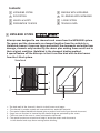
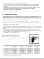
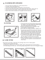
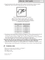
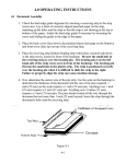
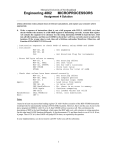
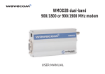
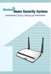
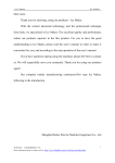
Atlas 190 • User’s guide
Atlas 190
GB User’s guide
GB
Contents:
16 METALBIND SYSTEM
56 BINDING WITH METALBIND
26 DESCRIPTION
66 DE-BINDING WITH METALBIND
36 HEALTH & SAFETY
76 C-BIND SYSTEM
46 PREPARATION TO WORK
86 TECHNICAL DATA
1 METALBIND SYSTEM
Atlas 190 was designed to use channels and covers from the METALBIND system.
The covers and the documents are clamped together from the outside by a
Metalbind channel. Covers are larger and protect the documents and edges from
damage, channels only touched by the covers plus making them secure and in
their original condition. Metalbind is the strongest binding method.
A special feature off the Atlas 190 is that it can also bind and de-bind covers
from the C-Bind system.
Metalbind
1
3
4
2
5
6
1 - The back wall of the channel is bent in to hold covers and pages.
2 - The channel is powder coated and covered with an embossed material.
3 - The special shaped Metalbind channel gives a perfect front look of your bound document.
4 - Pages are not touched or harmed by the channel they are protected by the covers.
5 - The front view of the cover is never misshaped or deformed.
6 - The special protrusions at each end help to centre the covers and documents
in the channel and stops them moving before binding.
GB
Atlas 190 • User’s guide
2 DESCRIPTION
4
10
5
11
1
4
3
2
6
7
7
8
8b
8
3
7
1 -bind and de-binding handle
2 -clamp lever
3 -binding slot
4 -de-binding hooks
5 - de-binding wedge (Metalbind)
6 -channel width selecting tool
7 - front bar of the COVERguide system
8 -back bar of the COVERguide
system with ruler
9 -fixed side stop
10 -adjustable side stop
11 -extended back support
9
10
3 HEALTH & SAFETY
• Before operating the equipment read the Health & Safety
precautions, manufacturers recommendations and the
operation/user manual
• The operation/user manual should be easily available at any
time for the operator
• The equipment must be kept away and out of reach
of children
• Equipment must be protected against dust and damp
and should be positioned on a strong and sturdy flat surface
• While binding, do not put fingers into the binding slot
• Be careful when moving the equipment it is very heavy
• Pay attention the de-binding wedge has sharp edges
• The machine must not be used for any other purposes
other than those indicated in the operating/user manual
• It is necessary to check and supervise if the equipment is being used and operated
correctly, before reporting any malfunctions or problems to the service department
or dealer
• Equipment must not be located outside or operated in temperatures under 8˚C / 46.4˚F
and must be operated in accordance with the general Health & Safety rules
failure to do so could cancel the guarantee
• Repairs must be carried out by authorized staff, during the guarantee period, failure to
do so could cancel the guarantee
4 PREPARATION TO WORK
After taking the device out of the packing box, start assembling the equipment, attach the
extended back support (11) on to the lower back support, to the pre drilled holes with the
Allen key and screws supplied, now fit the bind & de-binding handle (1) with the bolt and
Allen key supplied, in the hole in the side and tightened firmly.
Now place the two plastic bars called (COVER GUIDE SYSTEM) (7 & 8) in the binding slot
(8) with the ruler at the back of the slot, and the second bar (7) with magnets at the front
(see diagram on the opposite page)
The cover guide system has been specially designed to help you insert the covers and
documents into the channel easily and centre covers and documents when using smaller
channels.
It is very important that the cover guide system is fitted correctly in the binding slot (3)
the sloped edges of the bars should be facing each other in the binding slot please check by
looking at the diagram. (see diagram on the opposite page).
The equipment is now ready for work.
5
BINDING WITH METALBIND
1. Use channel width selecting tool (6) or table below to
choose size of channel.
Size of channel
H/p/H
H/p/T
S/p/S
O/p/O
5
7
10 - 31
32 - 60
10 - 33
34 - 63
10 - 34
35 - 63
10 - 38
39 - 67
10
13
16
61 - 89
90 - 118
119 - 148
64 - 92
93 - 121
122 - 150
64 - 92
93 - 121
122 -150
68 - 97
98 - 126
127 - 155
20
149-186
151 - 189
151 - 190
156 - 190
H = hard cover. p = pages. T = transparent cover. S = soft cover. O = no cover.
Example: H/p/H =(H) hard cover/ (p)pages / (H) hard cover
GB
Atlas 190 • User’s guide
7
8
B
Important!
7 - front edge guide for binding jaw The thickness of the documentation
8 - back guide with ruler
A - channel
B - binding jaw
A
to be bound must be at least 1,8 mm
(with the cover). If the documentation is
thinner, it is necessary to use the filling strips
called O.filling Sticky, available from OPUS
o make document thick enough to bind.
2. Make sure the binding bars also called cover guide system are correctly inserted into the binding slot (3) (see PREPARATION TO WORK and diagram above).
3. Pull up the bind and de-binding handle (1) to the open position, vertical.
4. Move the clamp lever (2) completely to the left.
5. Put the channel into the binding slot (3) between the bars (7 and 8) and insure that the channel is tight against the side stop (9) and the front of the channel is against the binding bar (8)
see diagram above. When using smaller channels than A4 fit the adjustable side stop (10). Centre the smaller
channel by using the ruler on the back bar in the slot and tighten the side stop (10)and do as
in point 5 above.
6. Close the clamp lever (2) to the right until you can feel resistant’s on the lever.
7. Take the pile of documents insure they are even, put it between the covers, check the pages
are centred in relation to the edges of covers.
8. Take the documents and covers and push carefully into the channel between the protrusions
in the binding slot. NOTE that 5 mm O.CHANNELS and all O.SIMPLE CHANNELS do not have protrusions. Note! Make sure the back cover is facing you.
9. Push down firmly on the bind & de-binding handle (1) holding the covers and documents
vertical till you feel the handle will go no further.
10. Now pull up the bind & de-binding handle (1) to the open position, vertical.
Move the clamp lever (2) to the left completely to take out the bound documents.
11. If the documents are not clamped together firm enough, repeat the process 9 and 10. above
again.
12. You may remove binded documentation.
1
Important!
Be sure the back cover faces you.
back cover
2
6 DE-BINDING WITH METALBIND
ba
co ck
ve
r
1. Lift the binding handle(1) up to the open position.
2. If fitted remove adjustable stop.
3. Ensure the clamp lever(2) is completely to the left,open.
4. Put the bound document flat on the equipment face down, back cover up.
5. Push the bound document, channel against the back support,firmly.
6. Open the bound document 5 to 6 pages from the back cover.
De-binding
1
2
7 C-BIND SYSTEM
7. Fit the right end of the wedge (5) blade edge towards
the channel, in the right hook (4) then place the left
end of the wedge into the left hook (4).
8.Move the clamp lever (2) to the right till you feel
some resistance, holding the lever.
9.Push down the binding handle (1) carefully, holding the clamp lever (2) at the same time, move the
handle (1) up and down at the same time move the
clamp lever (2) to the right carefully until the pages
are just loose enough to come out of the channel.
10.Lift the handle (1) up, release clamp lever (2) and remove the document together with the wedge, then
take the wedge out of the document carefully.
11.Make the planned changes to the document and
re-bind. The cover may be re-used (a maximum of
three times).
Accessories for binding, measuring, de-binding covers of the C-Bind system.
• Channel width selecting tool (6)
• O.CB Insert for Atlas 190. for binding C-Bind covers, two part kit for all covers (dig.1)
• O.CB Debinding tool for Atlas 190 - de-binding wedge (dig.2) and AA cover de-binding jig tool (dig.3)
dig. 1
dig. 2
dig. 3
Atlas 190 • User’s guide
GB
1. Using the channel width selecting tool (6), measure the thickness of the documents
without the cover or choose the appropriate cover from the chart below.
Sheet binding chart for the C-Bind system.
Measure the thickness of the sheets to be bound,
without covers. Select appropriate cover using the
chart above. Then use the same binding procedure
as Metalbind (see chapter 5). Channel size
Inumber of sheet
AA
soft cover 15-40
hard cover 20-40
A
41-90
B
91-120
C
121-145
D
146-185
2. Documents to bind must have a minimum thickness of 1.8 mm, thinner must be bound
using a filler strip called O.Filling Sticky from OPUS, these increase the thickness
for binding. Before binding C-BIND covers remove the Metalbind binding bar (8) with
ruler and insert the O.CB Insert for Atlas 190 binding bar, see (dig.1).
3. To de-bind C-BIND cover use O.CB de-binding wedge for Atlas 190 (Dig.2).
Important! The AA cover de-binding jig tool included in the (O.CB Debinding Tool for
Atlas 190) should be fitted on the spine edge of AA cover before debinding.
4. Follow the same binding and de-binding methods as in Metalbind, chapters 5 and 6.
While binding or de-binding with C-Bind System, front or back of cover may face you.
8
TECHNICAL DATA
• Binds and de-binds up to 190 sheets* = 380 pages **
• Dimensions: H-180 x W-435 x D-320 mm
• Net weight: 16.1 kg
• Gross weight: 18.5 kg
* Tested on 80 g/m2 paper
** Printed each side