1
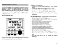
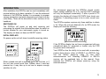
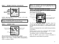
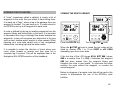
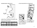
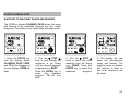
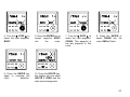
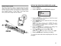
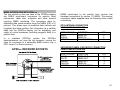
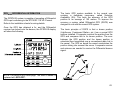
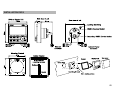
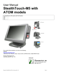
CONTENTS
INTRODUCTION
INTRODUCTION TO GPSPlus
1
3
OPERATION OF GPSPlus
INTRODUCTION
SWITCHING ON
INITIAL DISPLAYS
USING THE LIGHTS KEY
NOTES ABOUT ENTERING DATA
USING THE POS KEY
5
6
6
6
7
7
8
USING WAYPOINTS
INTRODUCTION TO WAYPOINTS
MARK FEATURE - INSTANT WAYPOINTS
MARK WAYPOINT TABLE
MAN OVERBOARD (MOB) FACILITY
VIEWING THE WAYPOINT LIBRARY
ENTERING AND USING WAYPOINTS
WAYPOINT BY LATITUDE AND LONGITUDE
PRESENT POSITION AS A WAYPOINT
ENTERING A WAYPOINT NAME
COPYING FROM WAYPOINT TO WAYPOINT
SORTING THE WAYPOINT LIBRARY
WAYPOINT BY RANGE AND BEARING
ERASING A WAYPOINT FROM THE LIBRARY
OTHER WAYPOINT SETUPS
11
11
12
13
15
16
16
17
19
20
21
22
23
24
25
USING ROUTES
INTRODUCTION TO ROUTES
VIEWING THE ROUTE LIBRARY
DIAGRAM OF A SIMPLE ROUTE
LISTING A STORED ROUTE
ROUTE PLANNING PAGE
DEFINING A ROUTE
EDITING A STORED ROUTE
OTHER ROUTE SETUPS
26
26
26
27
27
28
29
31
32
NAVIGATION WITH GPSPlus
INTRODUCTION TO NAVIGATION
SELECTING A WAYPOINT OR ROUTE
DISPLAYING THE NAV PAGES
CHANGING THE CURRENT LEG OF A ROUTE
33
33
34
35
38
SETTING UP THE GPSPlus
INTRODUCTION TO SETUPS
SELECTING THE RECEIVER INPUT TYPE
WAYPOINT ARRIVAL ALARM
AUTO ADVANCE RADIUS
ANCHOR ALARM
HDOP ALARM
CROSS TRACK ERROR ALARM
WAYPOINT ZONE ALARM
NETWORK SYSTEM ALARMS
SETTING THE CHART DATUM
SETTING A USER DATUM
SELECTING NMEA OUTPUT SENTENCES
NMEA CHECKSUMS
39
39
40
40
41
42
43
45
46
47
48
48
49
49
CONTENTS
SETTING DISPLAY TYPE (NORMAL/DEMO)
MANUALLY SETTING PRESENT POSITION
SETTING DISPLAY CONTRAST
SELECTING TIME/DATE DISPLAY
SETTING LOCAL TIME
SETTING THE DATE
SELECTING MAGNETIC OR TRUE BEARINGS
MAGNETIC VARIATION (AUTO/MANUAL)
SELECTING THE DISTANCE UNITS
COG AND SOG DAMPING
BEARINGS (RHUMB LINE/GREAT CIRCLE)
CHANGING THE DISPLAY LANGUAGE
MULTIPLE GPSplus DISPLAY INSTALLATIONS
GPSPlus INTERFACING
TRANSFERRING WAYPOINT DATA
DOWNLOADING VIA B&G NETWORK
DOWNLOADING VIA NMEA INTERFACE
UPLOADING WAYPOINTS
DOWNLOADING ROUTE DATA
NMEA INTERFACING WITH GPSPlus
NMEA CABLE CONNECTIONS
NMEA OUTPUT
NMEA OUTPUT SENTENCE LIST
GPS Plus DIFFERENTIAL INFORMATION
50
51
51
52
52
53
53
54
54
55
55
56
57
58
58
59
59
60
60
61
61
62
62
63
GPSPlus INSTALLATION
INSTALLATION OF THE DISPLAY UNIT
INSTALLATION OF THE ANTENNA UNIT
ROUTING THE GPS ANTENNA CABLE
64
64
65
67
APPENDIX
CHART DATUM LIST
68
68
INTRODUCTION TO GPSPLUS
The GPSPlus display unit processes the information from its
accurate 12 channel GPS antenna/receiver unit or from an
additional LORAN-C or DECCA receiver. The unit can
select between either of the two input devices to display
accurate positional information, along with waypoints, routes
and information concerning GPS satellites, LORAN-C T.D.'s
or DECCA L.O.P.'s.
POS key - Positional Data
• Position as Latitude and Longitude to three decimal
places.
• Course and Speed over the ground, (COG & SOG).
• Universal Time Co-ordinate (UTC), local time and date.
• Local sea current information, direction and speed.
• Satellite information, LORAN-C T.D's, DECCA L.O.P's.
• Use with the SETUP key for setting and adjusting
parameters.
GPSPLUS DISPLAY UNIT
WPT/MOB/MARK key - Waypoint, Man Overboard & Mark
• Waypoint library for up to 250 waypoints.
• One-touch Man Overboard (MOB) alarm with range and
bearing to MOB event.
• 20 One-touch instant entry "Mark" waypoints.
• Entry of waypoint latitude and longitude.
• Entry of present position as a waypoint.
• Name waypoints using up to 8 characters.
• Copying from one library waypoint to another.
• List and sort by waypoint name or number.
• Entry by range and bearing from present position.
• Erase waypoints from the library.
• "Download" waypoints via NMEA interface.
• "Uploading" waypoints from another NMEA position fixer.
• "Net download" waypoints to another GPSPlus display
unit.
• Use with the SETUP key for setting and editing
waypoints.
The GPSPlus display unit's six keys and control knob have
the following operating functions and features:
3
NAV key - Navigational Data
The NAV key only gives navigational data when a waypoint
or route (sailplan) has been entered and selected.
•
•
•
•
•
•
•
•
Bearing and distance to waypoint; Magnetic or True
bearings, Nautical or Statute miles, Rhumb-line or Great
Circle calculations.
Course to steer (CTS).
Cross track error (XTE) with off track and direction to
steer indicator.
Time to go (TTG) to waypoint.
Velocity made good (VMG) to waypoint.
Estimated time of arrival (ETA) at waypoint.
Forward or reverse route selection.
Use with the SETUP key for selecting target waypoint or
route to be used for navigation.
ROUTE key - Route defining and editing
LIGHTS/ENTER key - Adjusts the illumination level, and
when used with the SETUP key memorises any setting and
adjustments that have been made.
▼ STEP ▲ knob - Selects and lists functions, waypoints,
routes and is used to adjust values and data. When a
number or name is flashing the ▼ STEP ▲ knob can be
turned to alter the flashing display. Press the ENTER key to
confirm your selection.
GPSPlus ALARMS
The GPSPlus display has alarms that can be set and
adjusted to suit your requirements. When an alarm condition
is met the internal alarm buzzer will sound and the display
will indicate which alarm has been triggered. When the
GPSPlus is part of a fully integrated Network Instrument
system the alarm conditions will be displayed and sounded
by all Network display units.
Route library for up to 10 routes, with up to 40 waypoints
per route.
Route planning page gives range and bearing data
between any two library waypoints.
Edit existing routes; insert and delete waypoints from any
selected route.
"Download" route data via NMEA.
Use with the SETUP key for defining and editing routes.
The following alarms can be set and adjusted:
• Waypoint arrival alarm with automatic waypoint advance.
• Anchor watch alarm.
• HDOP alarm (GPS use only).
• Cross track error alarm.
• Waypoint zone alarm.
SETUP key - Used with other keys for setting and adjusting
data. Refer to the SETUP section of the handbook for a full
list of setups.
Refer to the SETTING UP THE GPSPlus for details on
setting and adjusting the alarms.
•
•
•
•
•
The GPSPlus display will also repeat alarms from Network
instruments when part of an integrated Network System.
4
INTRODUCTION
After installation the GPSPlus can be used immediately with
minimal setting up for basic operation. To use the advanced
features of the GPSPlus display it is necessary to program
various parameters and enter waypoints and routes into the
units library. These will be discussed in later sections of this
handbook.
SWITCHING ON
The GPSPlus will power up and start receiving and
processing the signals from the satellites when the switch or
contact breaker for your instruments supply is turned on.
The display unit does not have an ON/OFF switch.
On subsequent power-ups the GPSPlus should quickly
obtain enough satellites for a fix, and the WAIT message
will only be displayed momentarily. If after a period of 15
minutes the display still shows NO DATA then check your
installation. If everything seems to be in order consult your
dealer.
The GPSPlus system requires only three satellites to obtain
a `fix'. When the unit has obtained a fix (in GPS mode) the
display will show the following:
INITIAL DISPLAYS
On power-up the unit will show its satellite receiving status:
If the GPSPlus display has not been programmed with any
navigational data (i.e. waypoints or routes) only the POS
key gives useful information.
When a brand new unit is powered up for the first time, or if
the unit has moved more than 1500km since it was last
powered up, it may take up to an hour to acquire enough
satellites for a fix.
Your GPSPlus has the ability to be used with a secondary
position fixing device, either a LORAN-C or a DECCA. The
unit will initially power-up using its own GPS
antenna/receiver unit. Selecting LORAN-C or DECCA
receiver will be explained later in this manual. Once
selected the GPSPlus will always power-up using the
selected receiver.
5
USING THE LIGHTS KEY
NOTES ABOUT ENTERING DATA
The GPSPlus display unit has 3 levels of illumination and
off, controlled by the LIGHTS key. It also changes the
illumination level of the key legends. The LIGHTS key is
always illuminated so even in complete darkness the key
can be located.
•
When a number or name is flashing the ▼ STEP ▲ knob
can be turned to alter the flashing display, without the
need to press any other keys. To select the value that is
currently flashing, press the ENTER key.
•
When in a SETUP mode, if a key has not been pressed
for a period of 30 seconds the SETUP sequence will be
exited automatically.
•
The ▼ STEP ▲ knob increases values when turned
clockwise and decreases values when turned anticlockwise.
•
To end any SETUP sequence and return to normal
operation, press any key except ENTER or the
▼ STEP ▲ knob.
•
•
•
•
LIGHTS 0
LIGHTS 3
LIGHTS 2
LIGHTS 1
OFF
High
Medium
Low
6
USING THE POS KEY
Press the POS key to display the following pages:
PAGE 1
PAGE 2
PRESENT POSITION
Course Over Ground
COG, SOG and UTC
Magnetic Legend
KTS
Speed Over Ground
Latitude
Knots Legend
FIX
Longitude
UTC or one of the
options described below.
POS
POS key
HDOP or one of the
options described below.
POS
POS key
The text line at the bottom of the display shows different
information depending upon which type of position fixer is
being used for positional data. Text display variations are as
follows:
HDOP
A figure of merit where the lower the number the
better the accuracy of the fix (GPS only). This is
the normal display when using the GPSPlus
system.
GPS
Some GPS receivers do not output HDOP data.
GPS DIF Differential GPS.
LORAN-C Present position from Loran-C chain.
DECCA
Present position from Decca chain.
II
Integrated Instruments.
GPS DR The unit has not received valid data and is now
using dead reckoning. A speed and heading
input are required from the Network System.
Course Over Ground, Speed Over Ground & Universal Time
Co-ordinate (UTC has taken over from GMT as the World
Standard Time).
The data is displayed (by default) in the following units:
COG in degrees Magnetic (M). User selectable to True (T).
SOG in Knots (KTS). User selectable to Miles per Hour
(MPH) or Kilometres per Hour (KH). The text line can be
configured to display different time and date information as
follows:
LT
DATE
UTC/DATE
LT/DATE
Local Time, this can be set as required.
This can be set as required.
Alternating display of UTC and Date.
Alternating display of Local Time and Date.
For details about changed the default displays please refer
to the Setup section of this manual.
7
PAGE 3
PRESENT POSITION, COG AND SOG
NOTE: This information can only be displayed when the
GPSPlus is receiving speed and heading data from an
integrated Network System.
PAGE 5
RECEIVER INFORMATION PAGES
One of three different pages will be displayed depending
upon the receiver selected.
GPS SATELLITE INFORMATION:
Satellite elevation
Latitude and Longitude of present position on the main
display and SOG and COG.
FIX
Satellite azimuth
Signal to noise ratio
The selected satellite and total
number of satellites in view
Satellite PRN
POS
NOTE: The displayed values for SOG and COG will be in
the same units as selected for the previous page
PAGE 4
The fifth POS key page displays information about the
receiver that has been selected to supply positional data
(see SETUPS ON THE GPSPlus to select different receiver
inputs).
CURRENT FLOW
Direction of Current
Magnetic Legend
KTS
Speed of Current
POS key
Knots Legend
POS
POS key
Data can be displayed about each satellite being tracked by
the GPSPlus.
Satellite signal to noise ratio is displayed in dB: the higher
the number the better the signal strength.
The satellite number is the satellite transmitted PRN.
The local influences of sea current on the vessel.
Direction of sea current, in degrees Magnetic(M) or True(T).
Speed of sea current, in knots (KTS), kilometres/hour
(KPH), or miles/hour (MPH).
When the SETUP control knob is turned, information is
displayed about each satellite being tracked.
8
DECCA L.O.P. AND CHAIN INFORMATION:
LORAN-C T.D. INFORMATION:
Turn the ▼ STEP ▲ knob to display more L.O.P. data.
The text line displays SOG and COG.
Continue turning the ▼ STEP ▲ knob to display the current
chain or a value in Nautical Miles of uncertainty UNCERT (if
output by the Decca receiver) on the LCD text line.
If the ENTER key is pressed the identifiers will stop flashing,
press the POS key to make them flash again.
Turn the t STEP s knob to display more T.D. pairs.
9
INTRODUCTION TO WAYPOINTS
NAMING WAYPOINTS
A "waypoint" is simply a point you wish to go to. It can be an
anchorage, a point off a landmark, buoys, harbour
entrances or any position at sea. Whatever the waypoint, it
is necessary to know its position in latitude and longitude or
determine its range and bearing from your present position.
This can be taken directly from your chart.
It is possible to give any waypoint a name. This could be the
charted name of buoys, navigational markers, or any unique
name you wish to use. The name must not exceed eight
characters in length and can be any combination of letters,
numbers, spaces and the symbols <, >, /. All spaces count
as characters. For example:
The GPSPlus display can store 250 waypoints in its
memory, this is commonly called a waypoint library. The
waypoints are given unique numbers, and can also be
named, so they can be recalled when required. After a time
your waypoint library will contain all your most commonly
used navigational points. The waypoints in the library can
be edited if required, i.e. copied, named and deleted. This
will be necessary if you have used all of the 250 waypoint
library locations. Until at least one waypoint has been
entered into the GPSPlus library defining a route the
advanced navigational features obtained by pressing the
NAV key are not available.
ENTERING WAYPOINT DATA
Waypoints can be entered into the waypoint library of the
GPSPlus unit in many ways. The following is a list of these
methods:
1. Mark facility, one-touch waypoint entry.
2. Entry of waypoint latitude and longitude.
3. Entry of present position as a waypoint.
4. Copying from a library waypoint to another.
5. Entry by range and bearing from another waypoint.
6. Copying or "uploading" from another position fixer.
BUOY, <BUOY>, 123/BUOY, B U O Y
The following words are reserved for use by the GPSPlus
unit and can not be used as waypoint names:
INSERT
DELETE
START
END
All waypoints can be named before or after their position
has been entered. This allows you to generate a list of
library names and then at a later date enter the latitude and
longitude. The waypoint library can be sorted and listed
either numerically (default) from WPT 1 to WPT 250 or
alphabetically by name. Setting this feature is explained
later.
TRANSFER OF WAYPOINT DATA
It is possible to copy the waypoint library from the GPSPlus
display to another or any NMEA device. This is called
"downloading". There are two methods which will be
explained later. The reverse process, when waypoints are
copied from another GPSPlus display is called "uploading".
10
MARK FEATURE - INSTANT WAYPOINTS
The Mark feature allows 20 waypoints to be entered by
using a single key, the MARK key. This enables pots, drift
nets, and other points of interest along your present course
to be instantly memorised. Pressing the MARK key enters
your present position as a MARK into a reserved area of the
waypoint library. These mark waypoints are automatically
allocated the waypoint library names MARK01 to MARK20
and are waypoint numbers WPT 231 to WPT 250.
To enter a mark simply press the MARK key twice.
The first press will display the waypoint
library, the second and further presses
enter the MARKS. This can be carried
out 20 times.
After all 20 mark library locations have
been used the LCD will show
MARKFULL.
If the Marks are of particular interest then it is good practice
to copy them to other waypoint library locations, name them
for easy identification, and then erase the original MARK. By
erasing the original more MARKs can then be entered,
because once the MARK library locations are full no more
MARKs can be entered. These procedures are explained in
this section of the handbook.
MARKs can be used to define a route. If on a passage you
enter MARKs into the library, and then use them in the
correct order to define a route, they can be used in reverse
to lead the way home. These procedures are explained in
USING ROUTES, later in this handbook.
IMPORTANT NOTE: If MARK waypoints have been used to
create a route ensure that the MARK latitude and longitude
is as you expect. If the MARKs have been erased and then
re-entered (by pressing the MARK key) the MARK latitude
and longitude will have changed and the route could be
entirely different. THIS COULD ENDANGER YOU, YOUR
CREW AND YOUR VESSEL. CHECK BEFORE YOU
ENGAGE THE ROUTE.
It is suggested that you use a table to record your MARK
waypoints, it will help you identify and record them in the
future. The following pages could be copied for this purpose
or a table of your own design could be used.
Mark waypoints can be used exactly like any other waypoint
that you have entered using the methods described in the
following pages.
11
MARK NUMBER
MARK01 [WPT 231]
MARK POSITION
LAT
:
LONG
:
MARK REFERENCE
TIME
:
DATE :
LAT
LONG
:
:
TIME
DATE :
:
MARK02 [WPT 232]
LAT
LONG
:
:
TIME
DATE :
:
MARK03 [WPT 233]
:
:
TIME
DATE :
:
MARK04 [WPT 234]
LAT
LONG
LAT
LONG
:
:
TIME
DATE :
:
MARK05 [WPT 235]
LAT
LONG
:
:
TIME
DATE :
:
MARK06 [WPT 236]
:
:
TIME
DATE :
:
MARK07 [WPT 237]
LAT
LONG
:
:
TIME
DATE :
:
MARK08 [WPT 238]
LAT
LONG
LAT
LONG
:
:
TIME
DATE :
:
MARK09 [WPT 239]
:
:
TIME
DATE :
:
MARK10 [WPT 240]
LAT
LONG
MARK INFORMATION
12
MARK NUMBER
MARK11 [WPT 241]
MARK POSITION
LAT
:
LONG
:
MARK REFERENCE
TIME
:
DATE :
LAT
LONG
:
:
TIME
DATE :
:
MARK12 [WPT 242]
LAT
LONG
:
:
TIME
DATE :
:
MARK13 [WPT 243]
:
:
TIME
DATE :
:
MARK14 [WPT 244]
LAT
LONG
LAT
LONG
:
:
TIME
DATE :
:
MARK15 [WPT 245]
LAT
LONG
:
:
TIME
DATE :
:
MARK16 [WPT 246]
:
:
TIME
DATE :
:
MARK17 [WPT 247]
LAT
LONG
:
:
TIME
DATE :
:
MARK18 [WPT 248]
LAT
LONG
LAT
LONG
:
:
TIME
DATE :
:
MARK19 [WPT 249]
:
:
TIME
DATE :
:
MARK20 [WPT 250]
LAT
LONG
MARK INFORMATION
13
MAN OVERBOARD (MOB) FACILITY
NAV
WPT/MOB
1. Press and Hold the
WPT/MOB key for 3
seconds.
2. The display will flash
MANOVER
and
the
internal alarm will sound.
Press any key to silence
the
alarm.
3. The display will now
show the range and
bearing to the MOB event.
This display can also
obtained by pressing the
NAV
key.
4. Press the WPT/MOB
key to display the latitude
and longitude of the MOB
event.
WPT
POS
WPT/MOB
5. Press the POS key to
display current position in
latitude and longitude.
6. Press and hold the
MOB/WPT key for 3
seconds to return to
normal
operation.
7. The MOB event is
stored in the waypoint
library as WPT 230.
This waypoint will not be
automatically overwritten
by another MOB event, so
it must be erased from the
waypoint library using the
waypoint erase facility.
14
VIEWING THE WAYPOINT LIBRARY
ENTERING AND USING WAYPOINTS
Press the WPT/MOB key to the view the waypoint library.
If the WPT/MOB key was the last key that was pressed, the
display will show MARK## or MARKFULL for a few
moments.
The following pages describe how to use the many
waypoint functions in the order they are listed when the
SETUP key is pressed. The method of entering and
changing data is described in words and diagrams. These
will give you an indication of what you might expect to see.
B&G reserves the right to change the operation of the
instrument without prior notice, so variation may occur.
The flashing number below the WPT legend indicates which
library location is being viewed (1 to 250). By turning the
▼ STEP ▲ knob the flashing number will change selecting
each waypoint library location in turn.
If the library location is empty nOt USEd will be displayed.
When a waypoint library location has been used the latitude
and longitude of the waypoint in displayed in degrees and
minutes. The waypoint "name" will be displayed to the left of
the WPT number. If it has no name then a number with a
leading "W" will be displayed e.g. W001.
NOTES ABOUT ENTERING WAYPOINT DATA
•
•
•
•
When a number or name is flashing the ▼ STEP ▲ knob
can be turned to alter the flashing display, without the
need to press any other keys.
When in a SETUP mode, if a key has not been pressed
for a period of 30 seconds the SETUP sequence will be
exited automatically.
The ▼ STEP ▲ knob increases values when turned
clockwise and decreases values when turned anticlockwise.
To end any SETUP sequence and return to normal
operation, press any key except ENTER or the
▼ STEP ▲ knob.
15
ENTERING WAYPOINTS BY LATITUDE AND LONGITUDE
1. Select a point on a
chart,
determine
the
latitude and longitude.
Press the WPT/MOB key.
2. Press the SETUP key.
Turn the ▼ STEP ▲ knob
to select an empty WPT
number.
3. Press the ENTER key.
The DEGREES of latitude
will flash.
Use the ▼ STEP ▲ knob
to change the degrees.
5. Press the ENTER key.
The 10ths and 100ths of
MINUTES will flash.
Use the ▼ STEP ▲ knob
to change the value.
6. Press the ENTER key.
The 1000ths of MINUTES
will flash. Use the ▼ STEP
▲ knob to change the
value.
7. Press the ENTER key.
The N or S will flash.
Use the ▼ STEP ▲ knob
to
select
N
or
S.
4. Press the ENTER key.
The MINUTES of latitude
will flash.
Use the ▼ STEP ▲ knob
to change the minutes.
16
8. Press the ENTER key.
The
DEGREES
of
longitude will flash.
Use the ▼ STEP ▲ knob
to change the degrees.
9. Press the ENTER key.
The MINUTES of longitude
will flash.
Use the ▼ STEP ▲ knob
to change the minutes.
10. Press the ENTER key.
The 10ths and 100ths of
MINUTES will flash.
Use the ▼ STEP ▲ knob
to change the value.
12. Press the ENTER key.
The W or E will flash. Use
the ▼ STEP ▲ knob to
select W or E.
13. Press the ENTER key.
The waypoint setting will
be stored in the library.
14. Press the WPT/MOB
key to view the waypoint
library.
11. Press the ENTER key.
The 1000ths of MINUTES
will flash.
Use the ▼ STEP ▲ knob
to change the value.
17
PRESENT POSITION AS A WAYPOINT
1. Press the WPT/MOB
key.
2. Press the SETUP key.
Use the ▲ STEP ▼ knob
to select a WPT number.
3. Press the ENTER key.
The DEGREES of latitude
will flash.
4. Press the POS key, the
present position is now
entered into the selected
library location.
18
ENTERING A WAYPOINT NAME
1. Press the WPT/MOB
key. Use the ▼ STEP ▲
knob to view the waypoint
library.
2. Press the SETUP key
twice. The display will
show NAME WPT ##. Use
the ▼ STEP ▲ knob to
select a WPT number.
3. Press the ENTER key.
The first character will start
flashing. Use the ▼ STEP
▲ knob to change the
character.
5. Repeat stages 3 and 4
until all characters have
been entered, including
blanks.
6. When the last character
has been entered the
display will return to
NAME
WPT
##.
7. Entry of waypoint latitude
and longitude (if required)
can be carried out as
previously explained.
4. Press the ENTER key to
accept
the
displayed
character and advance to
the next.
19
COPYING FROM WAYPOINT TO WAYPOINT
1. Press the WPT/MOB
key. Use the ▼ STEP ▲
knob to select the target
WPT number (or name).
2. Press the SETUP key 3
times. The display will
show COPY A WAYPT.
5. Press the ENTER key to
copy the waypoint to the
library
location.
The
display will show COPY A
WAYPT.
6. Press the WPT/MOB
key. The display will show
you the "new" waypoint.
3. Press the ENTER key.
Use the ▼ STEP ▲ knob
to select the waypoint to
be copied. The waypoint
number and name will be
displayed.
4. Press the ENTER key.
Use the ▼ STEP ▲ knob
to
select
the
target
waypoint. The waypoint
number and name will be
displayed.
20
SORTING THE WAYPOINT LIBRARY
1. Press the WPT/MOB
key.
2. Press the SETUP key 4
times. The display will
show WP BY NUMBER.
3. Press the ENTER key.
The display will flash
NUMBER.
4. Press the ENTER key to
memorise the selection.
Use the ▼ STEP ▲ knob
to select the sorting
method.
21
ENTERING WAYPOINT BY RANGE AND BEARING FROM PRESENT POSITION
1. Press the WPT/MOB key.
Use the ▼ STEP ▲ knob to
view the waypoint library.
2. Press the SETUP key 5
times. The display will show
WPT### BY RB. Use the ▼
STEP ▲ knob to select a
number.
WPT
3. Press the ENTER key.
The range in nautical miles
will flash. Use the ▼STEP▲
knob to enter the range from
0.01
to
9.99nM.
5. Use the ▼ STEP ▲ knob
to select a waypoint (from
the library) to calculate the
range and bearing from. For
example BUOY WPT 1 is
used.
6. Use the ▼ STEP ▲ knob
to select a waypoint library
location
for
the
new
waypoint. Press the ENTER
key to memorise the new
range
and
bearing.
7. Press the WPT/MOB key
twice to display the latitude
and
longitude
of
the
waypoint. The waypoint can
be named if required.
4. Press the ENTER key.
The bearing in degrees will
flash. Use the ▼ STEP ▲
knob to enter the bearing
from 000° to 359°.
22
ERASING A WAYPOINT FROM THE LIBRARY
1. Press the WPT/MOB
key.
2. Press the SETUP key
six times, the display
shows ERASE.
Use the ▼ STEP ▲ knob
to select the waypoint. If
the waypoints have names
these will be displayed.
3. Press the ENTER key.
YES will flash.
Use the ▼ STEP ▲ knob
to select YES to erase or
NO to select another
waypoint.
4. Press the ENTER key to
erase
the
selected
waypoint (when YES is
displayed). If the knob is
turned another waypoint
can be selected for
erasure, or press the
WPT/MOB key to return to
the library.
23
OTHER WAYPOINT SETUPS
The SETUP button has other waypoint facilities beyond the
Waypoint Erase function. Three more waypoint functions
are available as follows:
1. DOWNLOAD WPT
2. UPLOAD WPTS
3. NET DOWNLOAD
These functions are used when transferring waypoint data
between other GPSPlus units and NMEA devices. They are
described in the GPSPlus Interfacing section of this
handbook.
24
INTRODUCTION TO ROUTES
VIEWING THE ROUTE LIBRARY
A "route" (sometimes called a sailplan) is simply a list of
waypoints in the order that you intend to travel along them.
It is made up of "legs", where a leg is the passage from one
waypoint to another. You can have up to 10 routes stored in
the GPSPlus and up to 40 waypoints in each route.
A route is defined leg by leg by recalling waypoints from the
waypoint library and storing them in the route. It is important
to remember that a leg is a straight line drawn between two
waypoints, it does not recognise any obstruction in the way
such as land, shallow water, wrecks, or other vessels. When
planning your route take careful note of any navigational
obstructions, including high and low water marks.
It is possible to select the direction of travel along your
route, either forward or reverse and then miss out a
complete leg if required. This will be explained later in the
Navigation With GPSPlus section of this handbook.
Press the ROUTE key.
Turn the ▼ STEP ▲ knob.
When the ▼ STEP ▲ knob is turned the ten routes will be
listed by number from 1 to 10 as USED or nOt USEd
depending upon the current state.
If the text line of the LCD shows NULL WPT ###, (where
### is a number from 1 to 250), it indicates that waypoint
### has been erased from the waypoint library and
therefore the route is now invalid. To overcome this either
redefine the route without the waypoint, or re-enter the
erased waypoint.
Below is a diagram of a simple route that will be used in this
section to demonstrate the use of the GPSPlus route
facilities.
26
LISTING THE WAYPOINTS OF A STORED ROUTE
DIAGRAM SHOWING A SIMPLE ROUTE
A simple table as shown below can be very helpful when
planning a route. The latitude and longitude of each
waypoint could be added if required.
ROUTE LEG
LEG 0
LEG 1
LEG 2
FROM
PPOS,
present position
MOORING
BUOY
TO
MOORING
BUOY
FISHING
Press the ROUTE key and
turn the ▼ STEP ▲ knob to
view the route library. The
first and last waypoint
name or numbers are
displayed on the text line.
Press the SETUP key and
turn the ▼ STEP ▲ knob to
list the route LEG by LEG.
27
ROUTE PLANNING PAGE
WAYPOINT TO WAYPOINT RANGE AND BEARING
The GPSPlus display PLANNING PAGE allows the range
and bearing to be calculated between any two, library
waypoints. This facility is very useful when planning a route.
1. Press the ROUTE key
until the display shows
PLANNING PAGE, FROM
and TO will be showing on
the text display. FROM will
flash.
2. Turn the ▼ STEP ▲
knob to cycle through the
waypoints in the library
until the desired waypoint
is displayed e.g. BUOY.
Press the ENTER key to
select
the
displayed
waypoint. TO will now
flash.
3. Turn the ▼ STEP ▲
knob to select the other
waypoint from the library
e.g. FISHIN. Press the
ENTER key to select the
displayed
waypoint.
4. The display will now
show the inter-waypoint
range and bearing. The
waypoint name or number
will continue to flash so
that other selections can
be made.
28
DEFINING A ROUTE
The route in the diagram on the previous page is used in
the following example.
When the waypoint library has been set to sort by name, the
display will only show the first six characters of any named
waypoint. If the waypoints in your library have not been
named then the waypoint number will be shown e.g. W001.
When sort by number is selected then the WP number is
displayed.
1. Press the ROUTE key.
Select a route to define
using the ▼ STEP ▲ knob.
2. Press the SETUP key to
begin route entry. END will
flash. When the right side
of the text display is
flashing, waypoints can be
selected from the library.
The start of a route is
always from your present
position
PPOS.
3. Turn the ▼ STEP ▲
knob to cycle through the
waypoints in the library
until the desired waypoint
is displayed e.g. MOORIN.
4. Press the ENTER key to
select
the
displayed
waypoint. The selected
waypoint will now appear
on the left of the display.
29
5. Turn the ▼ STEP ▲ to
select the next waypoint,
BUOY.
6. Press the ENTER key to
accept waypoint BUOY
into
the
route.
9. Press the ENTER key
again to complete the
route
definition.
10. Press the ROUTE key,
the display will now show
ROUTE 1, USED, and the
start and end waypoints.
7. Turn the ▼ STEP ▲ to
select the next waypoint,
FISHIN. This waypoint is
the last waypoint in this
route.
8. Press the ENTER to
select FISHIN into the
route. END will flash.
30
EDITING A STORED ROUTE
Any stored route in the route library can be edited.
Waypoints can be inserted into or deleted from any leg of
your defined route, or simply added on to the end. There is
also facility to delete the entire route from the route library. If
all the waypoints are deleted the route will be listed as nOt
USEd when the route library is viewed.
To edit a leg of a route proceed as follows:
INSERTING AND DELETING WAYPOINTS IN A ROUTE
1. Press the ROUTE key until ROUTE # is displayed.
Select the route to be edited from the route library with
the ▼ STEP ▲ knob.
2. Press the SETUP key and turn the▼ STEP ▲ knob to
list the route leg by leg.
3. When the leg to be edited is displayed press the
ENTER key.
4. The waypoint name or number will now flash.
5. Turn the ▼ STEP ▲ knob until the word INSERT or
DELETE is displayed.
6. Press the enter key to INSERT or DELETE a waypoint.
7. If DELETE has been selected the displayed waypoint is
immediately deleted, so you must be sure! The number
of legs will now have decreased by one.
8. If INSERT has been selected the ▼ STEP ▲ knob
allows the waypoint library to be listed (see DEFINING
A ROUTE). Press the ENTER key to select the
waypoint to be inserted. The number of legs will now
have increased by one.
ADDING WAYPOINTS TO THE END OF A ROUTE
1. Press the ROUTE key until ROUTE # is displayed.
Select the route to be edited from the route library with
the ▼ STEP ▲ knob. Press the SETUP key.
2. Turn the ▼ STEP ▲ knob until END is shown on the
right of the text display.
3. Press the ENTER key, END will now flash.
4. Turn the ▼ STEP ▲ knob to cycle through the waypoint
library until the desired waypoint is displayed.
5. Press the ENTER key to select the displayed waypoint.
END will continue to flash, allowing more waypoints to
be added if required.
6. Press the ENTER key again to end route editing.
DELETING ROUTES FROM THE ROUTE LIBRARY
1. Press the ROUTE key until ROUTE # is displayed.
2. Press the SETUP key twice. The display will show
ERASE, and ROUTE #. The route number will flash.
3. Turn the ▼ STEP ▲ knob to cycle through the route
library until the desired route is displayed.
4. Press the ENTER key, the display will flash YES.
5. Turn the ▼ STEP ▲ knob to change the display to NO if
you change your mind.
6. Press the ENTER key when YES is displayed to delete
the route. A DELETED ROUTE CANNOT BE UNDELETED.
31
OTHER ROUTE SETUPS
The SETUP key has another function beyond the Route
Erase function. This function, ROUTE DOWNLOAD, is
described in the GPSPlus Interfacing section of this
handbook.
32
NAVIGATION WITH GPSPLUS
The NAV key is used to give navigational information from
your present position to a specific waypoint, the "target"
waypoint. The target waypoint could be any waypoint in the
waypoint library or a waypoint that makes up one the legs of
a pre-defined route.
It is necessary to select a waypoint or a route before the
GPSPlus unit can calculate the data. The target waypoint
can be changed at any time so NAV information is available
about any waypoint in the library.
The following navigational information is available when a
target waypoint has been selected:
•
•
•
Location of waypoint
Waypoint identity (ID)
Bearing and distance from present position to
waypoint
•
Course to steer (CTS)
Cross track error (XTE)
•
•
Course over ground (COG)
Speed over ground (SOG)
•
•
Time to go (TTG)
•
Velocity made good (VMG)
Estimated time of arrival (ETA)
•
Bearings can be displayed in degrees with reference to
True or Magnetic North and distances can be displayed in
Nautical Miles, Statute Miles or Kilometres. The calculated
values can be Rhumb Line or Great Circle.
The NAV key is also used to select the direction of the
route, either forwards or reverse. This is the order in which
the waypoints are used.
NOTES: If when a route is selected or when following a
route the display shows the message NAV FAULT, it
means that the target waypoints of the route have been
deleted from the GPSPlus waypoint library. To overcome
this problem either redefine the route or re-enter the deleted
waypoint(s).
When following a route the GPSPlus will continue to display
navigational data after the vessel has passed the final
waypoint. The information will be based on the last waypoint
until another waypoint or route is selected. The displayed
value for cross track error (XTE) is based on an extended
line of the previous track.
When the GPSPlus is used in combination with a Network
PILOT that has NMEA data being supplied to the PILOT
Display via its NMEA interface, the NAV key allows the
GPSPlus to select the PILOT NMEA data for calculation of
the displayed navigational data.
IMPORTANT NOTE: If MARK waypoints have been used to
create a route ensure that the MARK latitude and longitude
is as you expect. If the MARKs have been erased and then
re-entered (by pressing the MARK key) the MARK latitude
and longitude will have changed and the route could be
entirely different. THIS COULD ENDANGER YOU, YOUR
CREW AND YOUR VESSEL. CHECK BEFORE YOU
ENGAGE THE ROUTE.
33
SELECTING OR CHANGING THE TARGET WAYPOINT OR ROUTE
1. Press the NAV key. If
the unit is not already
NAVing, nO PLAn will be
displayed. The text display
will invite you to press
SETUP.
2. Press the SETUP key,
the display will flash either
NO PLAN, or one of the
displays shown in 3.
3. Use the ▼ STEP ▲
knob
to
select
the
waypoint or the route to be
used for navigation. The
direction of the route is
also selected by choosing
ROUTE # FWD or ROUTE
# REV (when NMEA data
is
available
via
the
Network PILOT, PILOT
NMEA is also displayed).
4. Press the ENTER key to
memorise the selection.
Pressing the NAV key will
now display navigational
information.
34
DISPLAYING THE NAV PAGES
Press the NAV key to display the following pages of
navigational data:
PAGE 1
ROUTE SELECTED - USING ROUTE #
When a route has been selected from the route library the
display will show which route is selected, the direction of
travel along the route and the current leg.
SELECTED NAV DATA
One of three different pages will be displayed depending
upon whether a waypoint, route or Pilot NMEA data is being
used for NAV functions.
WAYPOINT SELECTED - POINt SELECtEd
This is the name or number of the target waypoint selected
for NAV functions.
PILOT NMEA INPUT - USING PILOT NMEA INPUT
When NMEA data is being supplied via the NMEA interface
of the Network PILOT display unit from a Chart Plotter the
GPSPlus display will let you know.
35
PAGE 2 BEARING AND DISTANCE
Bearing (brG) and Distance from present position to the
target waypoint. Bearing is displayed in degrees Magnetic
(M) and distance is displayed in nautical miles (nM) by
default.
PAGE 3 BEARING, DISTANCE, XTE, SOG AND COG
Bearing to target waypoint. Cross track error, alternating
with direction to steer. Speed Over Ground and Course
Over Ground, alternating with Distance to target waypoint.
PAGE 4 BEARING, XTE, TTG AND VMG
Bearing to target waypoint. Cross track error, alternating
with direction to steer. Time To Go (TTG) in hours and
minutes, alternating with Velocity Made Good (VMG) to
target waypoint.
PAGE 5 CTS, XTE AND DISTANCE
CTS Course to steer to target waypoint. Cross track error,
alternating with direction to steer. DIST Distance to the
target waypoint in nautical miles.
36
PAGE 6
ESTIMATED TIME OF ARRIVAL
WAYPOINT SELECTED
EtA POINT Estimated time of arrival at the target waypoint
in hours and minutes. The date, month and year are
displayed on the bottom line.
PAGE 7
LATITUDE AND LONGITUDE OF TARGET
Latitude and Longitude of target waypoint. The target
waypoint name or number is shown on the text display.
ROUTE SELECTED
EtA END Estimated time of arrival at the last waypoint of
the route in hours and minutes. The date, month and year
are displayed on the bottom line.
37
CHANGING THE CURRENT LEG OF A ROUTE
The GPSPlus allows any leg of the selected route to be
missed or skipped over so that the route can be changed
without inserting or deleting any waypoints. Once a route
has been selected proceed as follows:
1. Press the NAV key. The
display will show the last
NAV
page
displayed.
2. Press the SETUP key
three times. The display
will show the current leg
number of the selected
route, e.g. CURNT LEG 0.
3. Press the ENTER key,
the leg number will flash.
Use the ▼ STEP ▲ knob
to select a different leg
number.
4. Press the ENTER key to
memorise the selection.
The NAV key will now
display information about
the new leg
38
INTRODUCTION TO SETUPS ON THE GPSPLUS
The GPSPlus has many parameters that can be set if the
user wishes, some of these are alarms. The sequence for
adjusting or setting these parameters and alarms is similar
in every case, only the displayed information is different.
The SETUPs are arranged in a continuous list that you can
cycle through using the SETUP key. For a full description of
each SETUP with its selectable parameters please refer to
the table at the end of this section.
A short cut method allows you to start cycling through the
list from a different entry point determined by the POS
display. The following list illustrates this principle.
With
this
POS
page
displayed the SETUP list
starts from DISPLAY
DISPLAY
LOCAL TIM
DATE
With
this
POS
page
displayed the SETUP list
starts from BEARINGS
BEARINGS
AUTO MAG VAR
DISTANCE
COG SOG
BEARINGS
LANGUAGE
With
this
POS
page
displayed the SETUP list
starts from INPUT
INPUT
AUTO ADV
RADIUS
ANCHOR AL
HDOP ALRM
CROSS TRK
ZONE # AL
DATUM
USER DATUM
With
this
POS
page
displayed the SETUP list
starts from OUTPUT
OUTPUT
C / SUMS
TYPE
PRESENT POSITION
CONTRAST
39
SELECTING THE RECEIVER INPUT TYPE
WAYPOINT ARRIVAL ALARM
If your GPSPlus system has a LORAN-C or DECCA
receiver, connected to the second receiver socket on the
rear of the unit, this can be selected to give positional
information. All of the features and functions of the GPSPlus
can be used with any of the receivers. This allows you to
select a different position fixer if one becomes unreliable, or
to compare accuracy of position.
The waypoint arrival alarm is always active, i.e. it CANNOT
be disabled. It is used in conjunction with the auto advance
function. The auto advance function is used to automatically
select the next waypoint in a route or sailplan. The waypoint
arrival alarm is triggered when the vessel is within a preset
radius around the target waypoint. The alarm is triggered in
two ways.
1. Press the POS key so HDOP is displayed on the text
line.
1. When the vessel arrives at the target waypoint within the
radius set for the auto advance function the display will
sound its alarm and flash ARRIVED. Other Network units
will also sound their alarms.
2. Press the SETUP key. The display will show the current
INPUT device.
SEtUP
InPUt
GPS
3. Press the ENTER key GPS will now flash. Use the
▼ STEP ▲ knob to change the INPUT device,
LORAN-C, DECCA.
4. Press the ENTER key to memorise the new setting.
5.
After 30 seconds the display will return to present
position or press the POS key to return instantly.
40
WAYPOINT ARRIVAL CONT...
2. When the vessel DOES NOT arrive at the target waypoint
within the set radius for auto advance, BUT crosses an
imaginary line drawn through the waypoint perpendicular to
the rhumb-line between waypoints, the display will sound its
alarm and flash CROSSING. Other Network units will also
sound their alarms.
The action taken when the alarm is activated depends on
the AUTO ADVance status:
If AUTO ADVance is ON, the next waypoint in the route is
used when the vessel arrives or crosses the waypoint as
described above. When this occurs the alarm will sound and
the display flashes for five seconds, then the next waypoint
in the route will be automatically selected.
If AUTO ADVance is OFF, the next waypoint in the route is
used only when a key is pressed to silence the waypoint
arrival or crossing alarm. The alarm will sound and the
display flash until a key is pressed, then the next waypoint
in the route will be selected.
NOTE: When steering the boat with a Network PILOT, the
autopilot will not steer to the next waypoint until instructed to
do so by the helmsman. This is a safety feature. Refer to
the Steering to NMEA section of the PILOT owners manual.
SETTING AUTO ADVance FEATURE
1. Press the POS key.
2. Press the SETUP key until AUTO ADV is displayed.
SEtUP
AUtO ADV
OFF
41
WAYPOINT ARRIVAL CONT...
ANCHOR ALARM
3. Press the ENTER key, OFF will now flash.
Although the name of this alarm implies use when at anchor
it can be used to alert when drifting away from any specific
point or waypoint.
4. Use the ▼ STEP ▲ knob to select ON or OFF. NOTE:
The AUTO ADV feature is factory set to OFF.
SETTING AUTO ADVance rADIUS
The anchor alarm sets a circle of a specific radius around a
point. The latitude and longitude of the point is determined
by your position when the alarm is selected to ON. If the
boat should drift OUTSIDE the predetermined radius the
alarm will sound.
(If you have not previously done so, press the POS key.)
Press any key to silence the alarm.
5. Press the ENTER key to memorise your setting.
1. Press the SETUP key until rADIUS is displayed.
SEtUP
rADIUS
0.10NM
2. Press the ENTER key, the value will now flash.
3. Use the ▼ STEP ▲ knob to alter the value in the range
0.01 to 9.99NM. NOTES: The rAdIUS value is factory
set to 0.10NM. If Statute Miles or Kilometres have been
selected the value will be displayed in the appropriate
units.
4. Press the ENTER key to memorise your setting.
In the example above, the vessel can drift anywhere in the
shaded area determined by the alarm radius. When the
vessel moves from point A to point B the alarm will sound.
42
SETTING THE ANCHOR ALARM
HDOP ALARM
1. Press the POS key.
As in all radio navigation systems, the accuracy is affected
by the geometry of the situation. Probably the most familiar
examples of this today is the practice of avoiding "small
crossing angles" in Loran-C or Decca lines of position
(LOP). These hyperbolic systems operate with fixed site
transmitters so the angles are constant at any particular
location. GPS uses moving transmitters (satellites) and
therefore the geometry or crossing angles are constantly
changing. In 2-dimensional GPS navigation, the lines of
position are moving circles on the Earth’s surface that are,
at all points, equidistant from a satellite. The effects of
geometry on accuracy can be summarized in a single
number, called the Horizontal Dilution of Precision (HDOP).
2. Press the SETUP key until AnCHOr AL is displayed.
SEtUP
AnCHOr AL
OFF
3. Press the ENTER key, the display will flash the current
anchor alarm radius.
4. Use the ▼ STEP ▲ knob to alter the value in the range
0.01 to 9.99NM.
NOTE: The value is factory set to 1.00NM. Due to
external factors this alarm may not be reliable below
0.05NM. The value will be displayed in Statute Miles or
Kilometres if those units have been selected.
5. Press the ENTER key to memorise your setting. The
display will now flash the current alarm state.
The accuracy obtainable from a particular set of satellites is
equal to the pseudo-range measurements multiplied by the
HDOP. In order to avoid extra-ordinary errors due to short
periods of very poor geometry the GPSPlus software will not
use satellite constellations with an HDOP higher than
twelve. The HDOP alarm allows you to be alerted when the
HDOP value becomes larger than a preset value (up to 12).
6. Use the ▼ STEP ▲ knob to select ON or OFF.
NOTE: The anchor alarm is factory set to OFF.
7. Press the ENTER key to memorise your setting.
To change the alarm state without adjusting the radius, miss
out step 4.
43
GOOD SATELLITE GEOMETRY - LOW HDOP (<12)
SETTING THE HDOP ALARM
1. Press the POS key.
2. Press the SETUP key until HDOP ALrM is displayed.
3. Press the ENTER key, the display will flash the current
HDOP alarm limit.
4. Use the ▼ STEP ▲ knob to alter the limit in the range
0.1 to 12.0. NOTE: The value is factory set to 4.0.
5. Press the ENTER key to memorise your setting. The
display will now flash the current alarm state.
BAD SATELLITE GEOMETRY - HIGH HDOP (>12)
6. Use the ▼ STEP ▲ knob to select ON or OFF.
NOTE: The HDOP alarm is factory set to OFF.
7. Press the ENTER key to memorise your setting.
To change the alarm state without adjusting the limit, miss
out step 4.
44
CROSS TRACK ALARM
The Cross Track Error Alarm is triggered when the vessel
strays to the left or right of the course line drawn between
the last waypoint and the next waypoint in a route by more
than a preset distance, in other words, if the Cross Track
Error (XTE) value is larger than the value set.
SETTING THE CROSS TRACK ERROR (XTE) ALARM
1. Press the POS key.
2. Press the SETUP key until CrOSS trK is displayed.
SEtUP
CrOSS trK
OFF
3. Press the ENTER key, the display will flash the current
cross track error alarm limits.
4. Use the ▼ STEP ▲ knob to alter the value in the range
0.01 to 9.99NM.
NOTE: The value is factory set to 1.00NM. The value
will be displayed in Statute Miles or Kilometres if those
units have been selected.
5. Press the ENTER key to memorise your setting. The
display will now flash the current alarm state.
6. Use the ▼ STEP ▲ knob to select ON or OFF.
NOTE: The waypoint zone alarm is factory set to OFF.
7. Press the ENTER key to memorise your setting.
To change the alarm state without adjusting the limits, miss
out step 4.
45
WAYPOINT ZONE ALARM
The zone alarm sets a circle of a specific radius around any
waypoint. If the boat should drift INTO the predetermined
radius the alarm will sound. This is very useful when
attempting to remain near to a specific waypoint but without
getting too close, for example, a wreck particularly good for
fish. The GPSPlus display allows ten zone alarms to be set.
These could be used to create a barrier or exclusion zone
as shown in the example below. Press any key to silence
the alarm.
SETTING THE ZONE ALARM
1. Press the POS key.
2. Press the SETUP key until ZONE 0 AL is displayed.
Use the ▼ STEP ▲ knob to select the ZONE to be set
up.
SEtUP
ZONE 0 AL
OFF
3. Press the ENTER key, the display will flash the WPT
number. Select any waypoint from the waypoint library
with the ▼ STEP ▲ knob. Marks can be used.
4. Press the ENTER key, the display will flash the zone
alarm radius. Use the ▼ STEP ▲ knob to alter the value
in the range 0.01 to 9.99NM. NOTE: The value is
factory set to 1.00NM. The value will be displayed in
Statute Miles or Kilometres if those units have been
selected.
5. Press the ENTER key to memorise your setting. The
display will now flash the current alarm state.
6. Use the ▼ STEP ▲ knob to select ON or OFF.
NOTE: The zone alarm is factory set to OFF.
7. Press the ENTER key to memorise your setting.
Repeat the above stages for each waypoint zone.
46
NETWORK SYSTEM ALARMS
NETWORK PILOT ALARM DISPLAYS
The GPSPlus display has an internal buzzer that will sound
when an alarm condition is met on a Network unit that has
alarm functions: Network DEPTH and Network QUAD for
depth alarms and Network PILOT for Watch Alarm and Off
Course alarms. The unit will also display which alarm is
activated.
WATCH ALARM
To silence the internal alarm and return the display to
normal operation press any of the keys.
The Watch Alarm is a count-down
timer with is activated at the end of
the preset count-down period. The
display alternates between the
messages above.
DEPTH ALARM DISPLAY
Depth alarms can be set for the
following depth conditions:
• Shallow water
• Deep water
• Anchor Watch
OFF COURSE ALARM
The Off Course alarm is activated
when the boat deviates off course
by a preset amount. The display
alternates between the messages
above.
Check your Network DEPTH or QUAD unit to see which
alarm is activated.
47
SETTING THE CHART DATUM
SETTING A USER DATUM
The chart datum can be obtained from the navigational
chart you are using.
This is a user entered latitude and longitude offset obtained
from some charts.
1. Press the POS key.
NOTE: Before USER DATUM can be used USER
ENTERED must be selected as DATUM, see previous
section.
2. Press the SETUP key until dAtUM is displayed.
1. Press the POS key.
SEtUP
dAtUM
2. Press the SETUP key until USER DATUM is displayed.
WGS 84
3. Press the ENTER key, the displayed chart datum will
now flash.
SEtUP
USER DATUM
4. Use the ▼ STEP ▲ knob to select the required chart
datum. Refer to the datum list at the end of this manual.
NOTE: For user defined chart offsets select USER
ENTERED.
5. Press the ENTER key to memorise your setting.
3. Press the ENTER key, the display will now flash.
00.000N
00.000E
USER DATUM
4. Use the ▼ STEP ▲ knob and the ENTER key to enter
the required offset.
5. Press the ENTER key to memorise your setting.
48
SELECTING NMEA OUTPUT SENTENCES
NMEA CHECKSUMS
The setting allows the NMEA output sentences to be
selected as ON (transmitted) or OFF (not transmitted). It is
important that when interfacing with other NMEA devices
that the correct sentences are selected to ON. Initially all
sentences are OFF except RMB and RMC. Refer to
GPSPlus Interfacing for more information.
NMEA Output checksum: some older systems (e.g.
Hercules 390) do not accept this checksum data, so this
setup may need to be turned off.
1. Press the POS key.
2. Press the SETUP key until OUtPUt is displayed. The
NMEA sentence mnemonic will flash.
SEtUP
OUtPUt
APB - OFF
3. Use the ▼ STEP ▲ knob to view the list of NMEA
sentences and the current status (ON or OFF).
4. Press the ENTER key when the display shows the
required NMEA sentence mnemonic, ON or OFF will
now flash.
1. Press the POS key.
2. Press the SETUP key until C / SUMS is displayed. The
current status is displayed. The checksum is ON by
default.
SEtUP
C / SUMS ON
3. Press the ENTER key, the C / SUMS status ON/OFF will
now flash.
4. Use the ▼ STEP ▲ knob to select the required status.
5. Press the ENTER key to memorise your setting.
5. Use the ▼ STEP ▲ knob to change the status.
6. Press the ENTER key to memorise your setting.
49
DISPLAY TYPE
The unit can be set to run an internal demonstration
program, useful for learning to operate the instrument.
1. Press the POS key.
2. Press the SETUP key until tYPE is displayed.
SEtUP
tYPE
NORMAL
3. Press the ENTER key, the display will now flash.
4. Use the ▼ STEP ▲ knob to select NORMAL or DEMO.
5. Press the ENTER key to memorise your setting.
50
PRESENT POSITION
DISPLAY CONTRAST
This allows the user to input present position in degrees of
latitude and longitude. It is only required for some LORAN-C
and DECCA receivers or when using the unit in DR mode.
The contrast control can improve the display clarity.
Experiment to obtain the clearest display. The default
setting is 2.
Enter degrees of latitude and longitude
1. Press the POS key.
2. Press the SETUP key until PRESENT POSITION is
displayed.
SEtUP
PRESEnt
POSITION
3. Press the ENTER key, the display will now flash.
4. Use the ▼ STEP ▲ knob and the ENTER key to enter
the present position in degrees of Latitude and
Longitude.
1. Press the POS key.
2. Press the SETUP key until CONTRAST is displayed.
SEtUP
CONTRAST 2
3. Press the ENTER key, the display contrast value will now
flash.
4. Use the ▼ STEP ▲ knob to select the required contrast
level in the range 0 to 3.
5. Press the ENTER key to memorise your setting.
0°00.000N
0°00.000E
POSITION
5.
Press the ENTER key to memorise your setting.
51
TIME/DATE INFORMATION
SETTING LOCAL TIME
The text line of the LCD can display different combinations
of time and date information:
The local time display can be corrected for the current time
zone.
- Universal time coordinate
- Local time, user set
- Day, date, month and year
- Alternating display
- Alternating display
UTC
LT
DATE
UTC/DATE
LT/DATE
1. Press the POS key.
1. Press the POS key.
2. Press the SETUP key until LOCAL tIM is displayed.
SEtUP
LOCAL tIM
08-00
2. Press the SETUP key until dISPLAY is displayed.
3. Press the ENTER key, the time in hours will now flash.
SEtUP
dISPLAY
UTC
4. Use the ▼ STEP ▲ knob to adjust the hours.
5. Press the ENTER key. The time in minutes will now
flash.
6. Use the ▼ STEP ▲ knob to adjust the minutes.
3. Press the ENTER key, the display time and date line will
now flash.
7. Press the ENTER key to memorise your setting.
4. Use the ▼ STEP ▲ knob to select the required time and
date format.
5. Press the ENTER key to memorise your setting.
52
SETTING THE DATE
SETTING MAGNETIC OR TRUE BEARINGS
This setting allows the correct Day, Date, Month and Year to
be entered into the memory.
All bearings are displayed in degrees selected, Magnetic
(M) or True (T).
1.
Press the POS key.
1.
Press the POS key.
2.
Press the SETUP key until dAte is displayed.
2.
Press the SETUP key until bEArInGS is displayed.
3.
SEtUP
dAtE
SEtUP
bEArInGS
TUE 18 APR 95
MAGNETIC
Press the ENTER key. The displayed date will now
flash.
4.
Use the ▼ STEP ▲ knob to select the required date.
5.
Press the ENTER key. The month will now flash.
6.
Use the ▼ STEP ▲ knob to select the required month.
7.
Press the ENTER key. The year will now flash.
8.
Use the ▼ STEP ▲ knob to select the required year.
9.
Press the ENTER key to memorise the settings.
3.
Press the ENTER key, magnetic or true will now flash.
4.
Use the ▼ STEP ▲ knob to adjust the setting.
5.
Press the ENTER key to memorise your setting.
NOTE: The GPSPlus will work out the day automatically.
53
MAGNETIC VARIATION
DISTANCE UNITS
The magnetic variation is calculated by the unit when in
AUTO, however the value can be EntErEd if required.
All distances are displayed in the units selected, either NM Nautical Miles, M - Statute Miles or K - Kilometres. The
default setting is NM - Nautical Miles.
1. Press the POS key.
1. Press the POS key.
2. Press the SETUP key until MAG VAR is displayed. The
current mode will also be displayed. By default this is
AUTO, the calculated magnetic variation is displayed on
the bottom line
SEtUP
dIStAnCE
SEtUP
AUTO
MAG VAR
2. Press the SETUP key until dIStAnCE is displayed. The
current units will also be displayed.
NAUTICAL
0°W
3. Press the ENTER key, the display will now flash.
3. Press the ENTER key, the AUTO display will now flash.
4. Use the ▼ STEP ▲ knob change the distance units.
4. Use the ▼ STEP ▲ knob change from AUTO to
EnTEREd. Press the ENTER key.
5. Press the ENTER key to memorise the setting.
5. Use the ▼ STEP ▲ knob to enter the magnetic variation
in degrees from 0° to 180°. Press the ENTER key.
6. Use the t STEP s knob to enter W for West or E for
East.
7. Press the ENTER key to memorise the setting.
54
COG AND SOG DAMPING
CALCULATION METHOD FOR BEARINGS
This is the damping factor applied to Speed and Course
Over the Ground. When set to AUTO more damping is
applied when SOG is low, to prevent display jitter.
This setup is the method used by the unit to calculate
bearing and distance in NAV mode. The unit can be set to
use either Rhumb Line or Great Circle. Select the one most
suitable for your navigational needs.
1. Press the POS key.
1. Press the POS key.
2. Press the SETUP key until COG SOG is displayed. The
setting for damping will also be displayed.
SEtUP
COG SOG
DAMPING OFF
2. Press the SETUP key until bEArInGS is displayed. The
current setting will also be displayed.
SEtUP
bEArInGS
RHUMB LINE
3. Press the ENTER key, the display will now flash.
3. Press the ENTER key, the display will now flash.
4. Use the ▼ STEP ▲ knob change the damping.
4. Use the ▲ STEP ▼ knob change the setting.
5. Press the ENTER key to memorise the setting.
5. Press the ENTER key to memorise the setting.
55
CHANGING THE DISPLAY LANGUAGE
Changes the display language format from English to
French. All displays will be in the language selected. By
default the setting is English.
1. Press the POS key.
2. Press the SETUP key until LANGUAGE is displayed.
The current setting will also be displayed.
SEtUP
LANGUAGE
ENGLISH
3. Press the ENTER key, the display will now flash.
4. Use the ▼ STEP ▲ knob to change the setting.
5. Press the ENTER key to memorise the setting.
56
MULTIPLE GPSPLUS DISPLAY INSTALLATIONS
Installations with two or more GPSplus displays fitted must
select which GPSplus display will receive the data. When the
GPSplus displays and GPS antenna are powered up the
display should show the following:
If the above is not shown then press the SETUP key until
the following is displayed:
Press the ENTER key, the display will now show nOt USEd.
Turn the ▼ STEP ▲ knob. If the GPS has not yet locked
onto the position then nOt USEd will remain. If the GPS has
locked then nOt USEd will be replaced with the Latitude
and Longitude.
Press the ENTER key to memorise the selection. Press the
POS key to return to the position page.
57
TRANSFERRING WAYPOINT DATA
Up to four GPSPlus displays can be connected into a
Network System. This allows multiple NMEA receivers to be
used (remember that a single GPSPlus display allows two
NMEA receivers to be connected). To enable GPSPlus
displays to co-exist on the same network most of the setups
are common and the waypoint and route libraries must be
identical.
2. Downloading Via NMEA Interface
Waypoint data can also be transferred to other NMEA
devices. This is accomplished via the GPSPlus
display NMEA interface cable. The waypoints to be
downloaded are selected one by one, and then
transferred as a complete block of data in an NMEA
sentence $IIWPL.
When another GPSPlus display is added the data is usually
transferred automatically via the system network cables.
Occasionally automatic data transfer is unsuccessful and it
is necessary to manually initiate the transfer of waypoint
and route library data from one unit to the other. Data
transferred to other NMEA devices (not GPSPlus displays)
is always initiated manually.
UPLOADING
The copying of data, whether between GPSPlus displays or
other NMEA devices, is called Uploading or Downloading
depending on the direction of the data transfer.
The following procedures accomplish data transfer.
Uploading of waypoints is accomplished via the secondary
NMEA device socket (on the rear case of the GPSPlus
display) and cable directly from the position fixer selected.
All waypoints are transferred until the ENTER key is
pressed to terminate uploading.
DOWNLOADING
There are two methods of Downloading:
1. Downloading Via B&G Network
This is when data is copied between GPSPlus
displays via the B&G Network.
58
When downloading in this manner the waypoints are
transferred via the B&G Network interconnecting cables as
Network data. The waypoints are downloaded as one
complete block of data.
When downloading in this manner it is necessary to use a
special NMEA output cable (part number 610-OA-038)
available from your dealer. This cable is connected to the
secondary NMEA device socket of the GPSPlus display
unit. The waypoints to be downloaded are selected one by
one.
1. Press the WPT/MOB key.
1. Press the WPT/MOB key.
2. Press the SETUP key nine times. The display will show:
2. Press the SETUP key seven times. The display will show:
DOWNLOADING VIA B&G NETWORK
SEtUP
NET DOWNLOAD
3. Press the ENTER key. The display will show:
SEtUP
SENDING 250
The number of waypoints downloading will be displayed
counting down from 250.
NOTE: This method of transfer will automatically terminate
when all waypoint data has been copied or when a waypoint
with the same name as another already in the waypoint
library is received. It is possible that the GPSPlus will
display
and
DATABASE
FAULT
WAYPOINT
<name/number>. This indicates that there are two different
waypoints with the same number. Erase or copy one of the
waypoints to another (unused) library location if this occurs.
DOWNLOADING VIA NMEA INTERFACE
SEtUP
DOWNLOAD WPT
3. Press the ENTER key. The display will show:
SEtUP
dLOAd
WPT
The name of a waypoint for downloading will be displayed
and the WPT number will be flashing.
4. Use the ▼ STEP ▲ knob to select a waypoint.
5. Press the ENTER key to download the displayed
waypoint.
6. Repeat 4 and 5 until all the waypoints are transferred.
59
UPLOADING WAYPOINTS
DOWNLOADING ROUTE DATA
Uploading of waypoints is accomplished via the secondary
NMEA device socket and cable directly from the position
fixer selected. All waypoints are transferred until the ENTER
key is pressed to terminate uploading.
When multiple GPSPlus displays are used it may be
necessary to copy the route data (that is, all the waypoint
data stored in a route), between displays. This procedure is
similar to copying the waypoint library as previously
explained and is also called downloading.
1. Press the WPT/MOB key.
1. Press the ROUTE key until ROUTE # is displayed.
2. Press the SETUP key eight times. The display will
show:
SEtUP
UPLOAD WPTS
3. Press the ENTER key. The display will show:
2. Press the SETUP key three times. The display will show
DOWNLOAD.
ROUtE
1
USEd
DOWNLOAD
SEtUP
3. Press the ENTER key to download the route data.
UPLOADING 1
NOTE: It is possible for the GPSPlus to display an error
message DATA FAULT when downloading routes. This
indicates two routes with the same route number exist. If
this occurs erase one of the routes, or redefine another
route using the same waypoint data.
The number will increase indicating the total number of
waypoints transferred so far.
4. Press the ENTER key to terminate uploading.
NOTE: Uploading will stop automatically if a waypoint
having the same name as one already in the GPSPlus
library is uploaded.
60
NMEA INTERFACING WITH GPSPLUS
The two sockets on the rear case of the GPSPlus display
are NMEA input/output connectors for position fixing
instruments, radar sets, autopilots and other devices
requiring NMEA interfacing. The connectors allow bidirectional data communication using the NMEA 0183 v1.5
protocol. This allows input of positional data (latitude and
longitude) and other position fixer information (e.g. satellite
data) into the GPSPlus display unit for displaying, and
output of control sentences (including waypoint data) to a
position fixer.
In a standard GPSPlus system the GPSPlus
antenna/receiver unit uses the top connector, leaving the
other for connection to a secondary NMEA device (e.g. a
GPS, Loran-C or Decca receiver).
GPSPlus RECEIVER SOCKETS
NMEA input/output to the position fixer receiver has
hardware connections for version 1.5 NMEA. The receiver
connection cables supplied have the following colour coded
connections:
GPS ANTENNA CONNECTION
USING CABLE 610-OA-058
WIRE COLOUR
GREY
BLACK
SCREEN
FUNCTION
NMEA IN +
NMEA IN CABLE SHIELD
PIN
3
4
6
SECONDARY NMEA 0183 DEVICE CONNECTION
USING CABLE 610-OA-038
WIRE COLOUR
BLACK
WHITE
GREEN
YELLOW
SCREEN
FUNCTION
NMEA OUT +
NMEA OUT NMEA IN +
NMEA IN CABLE SHIELD
PIN
1
5
3
4
6
61
NMEA OUTPUT
NMEA OUTPUT SENTENCE LIST
The GPSPlus display software provides NMEA output from
both of the receiver connection sockets.
The following is a list of all the NMEA output sentences
available from the GPSPlus display unit including the initial
setting. The SETUP key allows selection of each sentence
as ON or OFF, allowing custom interfacing as required by
the end user.
It is necessary to select the required NMEA output
sentences as ON (transmitted) or OFF (not transmitted). To
determine which sentences are required refer to the NMEA
device handbook.
To turn a sentence from OFF to ON or vice versa:
1. Press the POS key to display the CURRENT FLOW
page.
2. Press the SETUP key once, the display will show
OUTPUT.
3. Turn the ▼ STEP ▲ knob to list all the GPSPlus output
sentence mnemonics. By default all are OFF except RMB
and RMC.
4. Press the ENTER key when the desired sentence is
displayed, ON (or OFF) will flash.
5. Use the ▼ STEP ▲ knob to change the flashing display.
6. Press the ENTER key to memorise the setting.
7. Repeat until all the required sentences are set.
APB
BOD
BWC
BWR
DBT
DTM
GL2
GL1
RMA
RMB
RMC
VDR
VHW
VLW
VTG
VWR
VWT
WCV
XTE
ZDA
ZTG
WPL
Autopilot sentence 'B'
Bearing, Origin to destination
Bearing and distance to waypoint (great circle)
Bearing and distance to waypoint (rhumb line)
Depth Below Transducer
Chart datum
Geographic Latitude and Longitude (NMEA V2.0)
Geographic Latitude and Longitude (NMEA V1.5)
Recommended minimum specific - Loran C
Recommended minimum navigation information
Recommended minimum navigation - GPS
Tidal Set and Drift
Heading and water speed
Distance Travelled through the Water
Actual track and ground speed
Wind bearing (relative) and speed
True Wind speed and Angle
Waypoint closure velocity
Cross track error
UTC time and date
Time of arrival at waypoint
Waypoint location
OFF
OFF
OFF
OFF
OFF
OFF
OFF
OFF
OFF
ON
ON
OFF
OFF
OFF
OFF
OFF
OFF
OFF
OFF
OFF
OFF
OFF
62
GPSPLUS DIFFERENTIAL INFORMATION
The GPSPLUS system is capable of accepting a Differential
GPS input conforming to the RTCM SC 104 V2.0 format.
Refer to the installation sheets for wiring details.
Once the GPS has obtained a fix, and the Differential
receiver has locked onto the beacon, the GPSPLUS display
will show the following:
The basic GPS system available to the normal user
contains a deliberate inaccuracy, called Selective
Availability (SA). This limits the accuracy of the GPS
position to an average of 100 metres. To improve the
accuracy a system called Differential GPS (DGPS) was
designed to run with the normal GPS system.
The basic principle of DGPS is that a known position
(Lighthouse, Coastguard Station, etc.) has a normal GPS
receiver installed. A computer monitors the position from the
GPS and compares this to its known position. The error
between the GPS position and the known position is
calculated then transmitted over a conventional radio link to
the vessel. The GPS on board the vessel recalculates the
position taking into account the errors. A separate receiver
and antenna are needed to receive the Differential beacon
signal.
NOTE: The above is not a new page. The value of HDOP is
replaced with GPS DIFF .
63
INSTALLATION OF THE DISPLAY UNIT
The display unit is supplied with a clip-in mounting bracket
which allows for easy installation. Access from behind is not
necessary to secure the unit in place. However, to prevent
theft and permanently fix the unit in position, locking studs
and thumb nuts are supplied.
SITING THE UNIT
The instrument is designed for mounting on or below deck.
A mounting position should be selected where it is:
• Easy to read by the helmsman
• On a smooth, flat surface
• At least 100mm (4") from a compass
• Protected from direct splashes of water to the rear of the
display case
• Accessible from behind for fitting locking studs if
required.
TOOLS REQUIRED
• 70mm (2¾") hole cutter
• 2.9mm, 5mm drills
• Screwdrivers
• Measuring tape or rule
• Cable clips or ty-wraps.
MOUNTING THE UNIT
Use the cutting template supplied to mark the centres of the
holes for the self-tapping screws, the fixing stud holes and
the mounting bracket.
• The template allows 4mm (5/32") between adjacent units
for the suncover. Increase this distance if required to a
maximum of 60mm (2 3/8") between units or 180mm (3
1/8") between centres. For greater distances between
units extension cables are available.
• Use a 70mm (2 3/4") diameter hole cutter for the
mounting bracket hole.
• Use a 2.9mm drill for the self-tapping holes.
• Use a 5mm drill for the locking stud holes.
• Secure the mounting bracket to the bulkhead with the
self-tapping screws supplied.
• Fit the rubber-sealing gasket around the mounting
bracket.
• Screw the locking studs into the back of the display head
(if required for security locking).
• Carefully pass the cable tails through the mounting
bracket hole, connect the plugs and sockets to sensor
cables, power cable and other Network display units as
required.
• Clip the display head into the mounting bracket (it is a
snug fit).
• Secure the instrument with the thumb nuts supplied (if
required).
64
INSTALLATION DATA
65
INSTALLATION OF ANTENNA UNIT
CHOOSING A LOCATION
MOUNTING THE ANTENNA UNIT
Select a suitable site for the antenna unit with reasonable
consideration of the following points:
• As close as possible to the vessel's deck, which has a
relatively unobstructed view of the horizon
• Avoid areas where the unit could become damaged, e.g.
where ropes or wires could become entangled
• Avoid installing unit at the mast top: this location
accentuates the boat’s motion
• Avoid areas of high vibration, e.g. engine housings and
radar installations
• Not within 60cm (2ft) of other antennas, e.g. VHF, SSB
• Above or below a radar's cone of transmission
• Below and at least 3m (10ft) away from satellite
communications equipment
The GPS antenna unit may be pole mounted. The threaded
socket at the base of the unit will accept a 1¼" straight
thread. The GPS antenna unit only requires hand tightening
on to the pole mount. Over tightening with a tool could
damage the threaded socket at the base of the unit.
Dense wood or metal structures will shield the unit from
satellite signals. However, stays, masts and relatively dry
sails will not interfere with reception. The unit can receive
signals through glass, canvas and thin fibreglass (for
example, a wheelhouse or saloon area), however it would
be advisable to try such a location before permanent fixture.
The pole mounting arrangement of the GPS antenna unit
makes it easy for you to remove and store it in a safe and
secure place when not in use. For permanent installation it
is advisable to drill and pin the GPS antenna unit. This will
discourage theft and prevent accidental loosening.
Alternatively the GPS antenna can be split into two parts by
removing the four screws in the underside. The lower part
can be discarded, leaving the GPS antenna with a flat base,
which can be mounted on a cabin top or “A” frame.
If you choose this mounting option secure the GPS antenna
from underneath using 4 x M3 machine screws. Care should
be taken to trim overlong screws so no more than 7 turns of
the thread are inside the GPS antenna.
66
ROUTING THE GPS ANTENNA CABLE
The GPS antenna unit is supplied with a 9 metre (30ft),
shielded multicore cable. The cable should be routed to the
GPSPlus Display unit junction box and then cut to length.
For connection details refer to the installation sheet supplied
with your system.
When routing the antenna cable consideration should be
given to the following guidelines:
AVOID:
•
Sharp bends or kinks in the cable
•
Hot surfaces e.g. exhaust manifolds or stacks
•
Rotating or reciprocating equipment
•
Sharp or abrasive surfaces
•
Door, hatch and window jambs
•
Corrosive fluids or gases
67
LIST OF CHART DATUMS
GPSPlus
NAME
ADINDAN
CHART DATUM
ADINDAN
COUNTRIES
Ethiopia
Mali
Senegal
Sudan
AFGOOYE
Somalia
AFGOOYE
Bahrain
AIN EL ABD AIN EL ABD 1970
Island
Cocos
ANNA
1 ANNA 1 ASTRO 1965
Islands
ASTRO
ARC 1950
Botswana
ARC 1950
Lesotho
Malawi
Swaziland
Zaire
Zambia
Zimbabwe
ARC 1960
Kenya
ARC 1960
Tanzania
ISLAND Ascension
ASCENSIO ASCENSION
1958
Island
N 58
ASTRO BEACON "E"
Iwo
Jima
AST
Island
BECON E
B4
SOROL Tern Island
AST B4 S ASTRO
ATOLL
ATO
AST
DOS
71/4
ASTRONOM
IC S
AUSTRALIA
66
AUSTRALIA
84
BELLEVUE
BERMUDA
1957
BOGOT
OBSERV
CAMPO
INCHAU
CANTON
ASTRO
CAPE
CAPE
CANAVER
ASTRO DOS 71/4
St.
Helena
Island
ASTRONOMIC STATION Marcus
1952
Island
AUSTRALIA GEODETIC Australia
1966
Tasmania
AUSTRALIA GEODETIC As above
1984
BELLEVUE (IGN)
Efate Islands
Erromango
Islands
BERMUDA 1957
Bermuda
Islands
BOGOTA
Colombia
OBSERVATORY
CAMPO INCHAUSPE
Argentina
CANTON ASTRO 1966
CAPE
CAPE CANAVERAL
CARTHAGE CARTHAGE
CHATHAM 1971
CHATHAM
1971
CHAU
ASTRO
CHAU ASTRO
Phoenix
Islands
South Africa
Florida
Bahama
Islands
Tunisia
Chatham
Island (New
Zealand)
Paraguay
68
CORREGO
ALEG
DJAKARTA
CORREGO ALEGRE
Brazil
DJAKARTA (BATAVIA)
DOS 1968
DOS 1968
Sumatra
Island
(Indonesia)
Gizo Island
(New
Georgia
Islands)
Easter Island
EASTER IS EASTER ISLAND 1967
67
EUROPEAN EUROPEAN 1950
50
Austria
Belgium
Denmark
Finland
France
Germany
Gibraltar
Greece
Italy
Luxembourg
Netherlands
Norway
Portugal
Spain
Sweden
Switzerland
EUROPEAN EUROPEAN 1979
79
FINLAND
GANDAJIK
A
GEODETIC
49
GUAM 1963
GUX
1
ASTRO
HJORSEY
1955
HONG
KONG 63
INDIAN
VIETN
Austria
Finland
Netherlands
Norway
Spain
Sweden
Switzerland
FINLAND HAYFORD 1910 Finland
GANDAJIKA BASE
Republic of
Maldives
GEODETIC DATUM 1949 New Zealand
GUAM 1963
GUX 1 ASTRO
HJORSEY 1955
Guam Island
Guadalcanal
Island
Iceland
HONG KONG 1963
Hong Kong
INDIAN
Thailand
Vietnam
69
LIST OF CHART DATUMS
INDIAN
INDIAN
IRELAND
1965
ISTS
073
AST
JOHNSTON
IS
KANDAWA
LA
KERGUELE
N IS
KERTAU
1948
LC
ASTRO
LIBERIA
1964
LUZON
MINDAN
LUZON
PHILLIP
IRELAND 1965
Bangladesh
India
Nepal
Ireland
ISTS 073 ASTRO 1969
Diego Garcia
JOHNSTON ISLAND 1961 Johnston
Island
KANDAWALA
Sri Lanka
KERGUELEN ISLAND
KERTAU 1948
5 L.C.5 ASTRO
MAHE 1971
LIBERIA 1964
LUZON
LUZON
MAHE 1971
Kerguelen
Island
West
Malaysia
Singapore
Cayman
Brac Island
Liberia
Mindanao
Island
Phillippines
(excluding
Mindanao
Island)
Mahe Island
MARCO
ASTRO
MASSAWA
MARCO ASTRO
MERCHICH
MIDWAY
ASTRO
MINNA
NAHRWAN
OMAN
MERCHICH
MIDWAY ASTRO 1961
NAHRWAN
UAE
NAHRWAN
SAUD
NAPARIMA
BWI
NA CONUS
NAHRWAN
NA
ALASKA
NA
BAHAMA
NA
SAN
SALVA
NA
CANADA
NORTH AMERICAN 1927
MASSAWA
MINNA
NAHRWAN
NAHRWAN
NAPARIMA, BWI
NORTH AMERICAN 1927
NORTH AMERICAN 1927
NORTH AMERICAN 1927
NORTH AMERICAN 1927
NA CANAL NORTH AMERICAN 1927
ZON
Salvage
Islands
Eritrea
(Ethiopea)
Morocco
Midway
Island
Nigeria
Masirah
Island
(Oman)
United Arab
Emirates
Saudi Arabia
Trinidad and
Tobago
Mean value
(CONUS)
Alaska
Bahamas
Island
San Salvador
Island
Canada
(Newfoundla
nd Island)
Canal Zone
70
NA
CARIBBEA
N
NA
CENTRAL
NORTH AMERICAN 1927
NORTH AMERICAN 1927
NORTH AMERICAN 1927
NA CUBA
NORTH AMERICAN 1927
NA
GREENLAN
D
NA MEXICO NORTH AMERICAN 1927
Caribbean Barbados
Caicos
Islands
Cuba
Dominican
Republic,
Grand
Cayman,
Jamaica
Leeward
Islands
Turks Islands
Central
America
Belize
Costa Rica
El Salvador
Guatemala
Honduras
Nicaragua
Cuba
Greenland
(Hayes
Peninsula)
Mexico
N AMERICA NORTH AMERICAN 1983
83
OBSERVAT
ORIO
OBSERVATORIO 1966
OLD
EGYPTIAN
OLD
HAWAIIAN
OMAN
OS OF GB
36
OLD EGYPTIAN
Alaska
Canada
Central
America
CONUS
Mexico
Corvo
Flores
Islands
(Azores)
Egypt
OLD HAWAIIAN
Mean Value
OMAN
Oman
ORDNANCE SURVEY OF England
GB 1936
Isle of Man
Scotland
Shetland
Islands
Wales
Canary
PICO LAS PICO DE LAS NIEVES
Islands
NIE
PITCAIRN ASTRO 1967
Pitcairn
PITCAIRN
Island
AST
South Chile
PROV
S PROVISIONAL
S.CHILEAN 1963
CHILE
71
LIST OF CHART DATUMS
PROV
AMER
S PROVISIONAL
S.AMERICAN 1956
PUERTO
RICO
QATAR
NATION
QORNOQ
PUERTO RICO
REUNION
REUNION
QATAR NATIONAL
QORNOQ
ROME 1940
ROME 1940
SANTO
DOS
SAO BRAZ
SANTO (DOS)
SAPPER
HILL
SAO BRAZ
SAPPER HILL 1943
Bolivia
Chile
Colombia
Equador
Guyana
Peru
Venezuela
Puerto Rico
Virgin Islands
Qatar
South
Greenland
Mascarene
Island
Sardinia
Island
Espirito
Santo Island
Sao Miguel
Santa Maria
Islands
(Azores)
East
Falkland
Island
SCHWARZE SCHWARZECK
CK
S AMERICA SOUTH AMERICAN 1969
69
S ASIA
SE BASE
SOUTH ASIA
SOUTHEAST BASE
SW BASE
SOUTHWEST BASE
SWEDEN
TIMBALAI
48
RT90 (RT38) SWEDEN
TIMBALAI 1948
Namibia
Argentina
Bolivia
Brazil
Chile
Colombia
Ecuador
Guyana
Paraguay
Peru
Venezuela
Trinidad and
Tobago
Singapore
Porto Santo
Madeira
Islands
Faial
Graciosa
Pico
Sao Jorge
Terceira
Islands
(Azores)
Sweden
Brunei
East
Malaysia
(Sarawak,
Sabah)
72
TOKYO
TOKYO
TRISTAN
AST
VITI LEVU
TRISTAN ASTRO 1968
WAKEENIWETK
ZANDERIJ
WGS 72
WAKE ENIWETOK 1960
WGS 84
USER
ENTERED
VITI LEVU 1916
ZANDERIJ
WORLD
GEODETIC
SYSTEM 1972
WORLD
GEODETIC
SYSTEM 1984
User entered Lat. and
Long. offset
Japan
Korea
Okinawa
Tristan
da
Cunha
Viti
Levu
Island
(Fiji Islands)
Marshall
Islands
Surinam
73