1
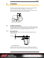
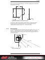
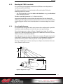
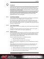
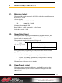
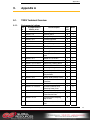
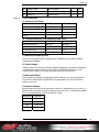
TGSS
True Ground Speed Sensor (TGSS) 740
User Manual HY33-5005-IB/US
Ed. 01/2012
UM-TGSS-740000-00-201201-03
Parker Hannifin Corporation
Electronic Controls Division
1305 Clarence Avenue
Winnipeg, MB R3T 1T4 Canada
Office +1 204 452 6776
Fax
+1 204 478 1749
http://www.parker.com/ecd
http://www.vansco.ca
http://www.iqan.com
Copyright 2012 © Parker Hannifin Corporation. All rights reserved. No part of this work may be
reproduced, published, or distributed in any form or by any means (electronically,
mechanically, photocopying, recording, or otherwise), or stored in a database retrieval system,
without the prior written permission of Parker Hannifin Corporation in each instance.
Warning!
FAILURE OR IMPROPER SELECTION OR IMPROPER USE OF THE PRODUCTS AND/OR
SYSTEMS DESCRIBED HEREIN OR RELATED ITEMS CAN CAUSE DEATH, PERSONAL INJURY
AND PROPERTY DAMAGE.
•
This document and other information from Parker Hannifin Corporation, its subsidiaries and
authorized distributors provide product and/or system options for further investigation by users
having technical expertise.
•
The user, through its own analysis and testing, is solely responsible for making the final selection of
the system and components and assuring that all performance, endurance, maintenance, safety
and warning requirements of the application are met. The user must analyze all aspects of the
application, follow applicable industry standards, and follow the information concerning the product
in the current product catalog and in any other materials provided from Parker or its subsidiaries or
authorized distributors.
•
To the extent that Parker or its subsidiaries or authorized distributors provide component or system
options based upon data or specifications provided by the user, the user is responsible for
determining that such data and specifications are suitable and sufficient for all applications and
reasonably foreseeable uses of the components or systems.
Offer of Sale
The items described in this document are hereby offered for sale by Parker Hannifin Corporation, its
subsidiaries or its authorized distributors. This offer and its acceptance are governed by the provisions
stated in the "Offer of Sale" elsewhere in this document, or available at www.parker.com.
Contents
Contents
1. Introduction
1.1.
Safety symbols
2. Precautions
2.1.
4
4
5
General safety regulations
5
2.1.1.
2.1.2.
2.1.3.
2.1.4.
6
6
6
6
Construction regulations
Safety during installation
Safety during start-up
Safety during maintenance and fault diagnosis
3. Product Description
7
3.1.
TGSS
7
3.2.
Compliances
8
4. Installation
9
4.1.
Installation Guidelines
4.2.
4.1.1. Mounting Bracket
4.1.2. Mounting Angle
4.1.3. Mounting the TGSS to a vehicle
4.1.4. Line of sight clearance
4.1.5. Installation Validation
Performance Considerations
5. Technical Specifications
9
9
10
11
11
12
13
14
5.1.
Microwave Output
14
5.2.
Speed Output Signal
14
5.3.
Radar-Present Output
14
5.4.
Connectors
15
6. Electrical Specifications
16
7. Environmental Specifications
17
8. Mechanical Specifications
18
8.1.
Dimensions
9. Appendix A
9.1.
18
19
TGSS Technical Overview
19
9.1.1.
19
Environmental ratings
10. Index
True Ground Speed Sensor (TGSS) 740
23
3
Introduction
1.
Introduction
These instructions are meant as a reference tool for the vehicle manufacturer's
design, production, and service personnel.
The user of this manual should have basic knowledge in the handling of electronic
equipment.
1.1.
Safety symbols
Sections regarding safety, marked with a symbol in the left margin, must be read and
understood by everyone using the system, carrying out service work or making
changes to hardware and software.
The different safety levels used in this manual are defined below.
WARNING
Sections marked with a warning symbol in the left margin, indicate that a hazardous
situation exists. If precautions are not taken, this could result in death, serious injury
or major property damage.
CAUTION
Sections marked with a caution symbol in the left margin, indicate that a potentially
hazardous situation exists. If precautions are not taken, this could result in minor
injury or property damage.
NOTICE
Sections marked with a notice symbol in the left margin, indicate there is important
information about the product. Ignoring this could result in damage to the product.
Contact the manufacturer if there is anything you are not sure about or if you have
any questions regarding the product and its handling or maintenance.
The term "manufacturer" refers to Parker Hannifin Corporation.
True Ground Speed Sensor (TGSS) 740
4
Precautions
2.
Precautions
2.1.
General safety regulations
Work on the hydraulics control electronics may only be carried out by trained
personnel who are well-acquainted with the control system, the machine and its
safety regulations.
WARNING
Mounting, modification, repair and maintenance must be carried out in accordance
with the manufacturer's regulations. The manufacturer has no responsibility for any
accidents caused by incorrectly mounted or incorrectly maintained equipment. The
manufacturer does not assume any responsibility for the system being incorrectly
applied, or the system being programmed in a manner that jeopardizes safety.
WARNING
Damaged product may not be used. If the control system shows error functions or if
electronic modules, cabling or connectors are damaged, the system shall not be
used.
WARNING
Electronic control systems in an inappropriate installation and in combination with
strong electromagnetic interference fields can, in extreme cases, cause an
unintentional change of speed of the output function.
NOTICE
As much as possible of the welding work on the chassis should be done before the
installation of the system. If welding has to be done afterwards, the electrical
connections on the system must be disconnected from other equipment. The
negative cable must always be disconnected from the battery before disconnecting
the positive cable. The ground wire of the welder shall be positioned as close as
possible to the place of the welding. The cables on the welding unit shall never be
placed near the electrical wires of the control system.
True Ground Speed Sensor (TGSS) 740
5
Precautions
2.1.1.
Construction regulations
CAUTION
The vehicle must be equipped with an emergency stop which disconnects the supply
voltage to the control system's electrical units. The emergency stop must be easily
accessible to the operator. The machine must be built if possible, so that the supply
voltage to the control system's electrical units is disconnected when the operator
leaves the operator’s station.
2.1.2.
Safety during installation
CAUTION
Incorrectly positioned or mounted cabling can be influenced by radio signals which
can interfere with the functions of the system.
2.1.3.
Safety during start-up
WARNING
The machine's engine must not be started before the control system is mounted and
its electrical functions have been verified.
Ensure that no one is in front, behind or nearby the machine when first starting up
the machine.
Follow the instructions for function control in the Start-up section.
2.1.4.
Safety during maintenance and fault diagnosis
CAUTION
Ensure that the following requirements are fulfilled before any work is carried out on
the hydraulics control electronics.
• The machine cannot start moving.
• Functions are positioned safely.
• The machine is turned off.
• The hydraulic system is relieved from any pressure.
• Supply voltage to the control electronics is disconnected.
True Ground Speed Sensor (TGSS) 740
6
Product Description
3.
Product Description
3.1.
TGSS
The true ground speed sensor (TGSS) uses the principle of Doppler shift to
determine the ground speed of the vehicle or other type of equipment. A microwave
signal that is transmitted out of the sensor, reflects off the target and is received by
the sensor. When the target (terrain) is moving relative to the sensor, there is a
change in the frequency of the reflected signal (Doppler shift). The ground speed is
calculated by measuring the change in frequency.
The TGSS is enclosed in a black plastic case, which is potted to cover the electronics.
The TGSS has a short cable terminated with a connector.
Figure 1: TGSS with Deutsch DT04-4P connector
Custom units with different cable lengths and connector types may be configured for
OEM customers. Contact your Parker Vansco representative.
True Ground Speed Sensor (TGSS) 740
7
Product Description
3.2.
Compliances
This device complies with RSS 210 of Industry Canada. Operation is subject to the
following two conditions: (1) this device may not cause interference, and (2) this
device must accept any interference, including interference that may cause
undesired operation of this device.
"Ce dispositif se conforme à la norme CNR-210 d'Industrie Canada. Les
conditions suivantes s'appliquent à l'utilisation du dispositif:
(1) le dispositif ne doit pas causer d'interférence radioélectrique, et (2) le
dispositif doit être en mesure d'accepter toute interférence radioélectrique,
même si celle-ci est susceptible de compromettre son fonctionnement."
FCC ID: MGR740030A
This device complies with Part 15 of the FCC rules. Operation is subject to the
following two conditions: (1) this device may not cause harmful interference, and (2)
this device must accept any interference received, including interference that may
cause undesired operation.
NOTICE
Any changes or modifications not expressly approved by the party responsible for
compliance could void the user's authority to operate the equipment.
True Ground Speed Sensor (TGSS) 740
8
Installation
4.
Installation
The TGSS is typically installed at a height of 0.3 to 1 meter (1 to 3 feet) above the
ground. The maximum height of installation is 1.22 meters (4 feet).
The sensor mounts to a bracket on the underside of the vehicle where the sensor
may be directed in either the forward or reverse direction.
35°
Figure 2: Typical installation
4.1.
Installation Guidelines
The TGSS 740 Radar measures motion relative to itself. It is important to prevent
unwanted motion in order to achieve optimal performance. The unwanted motion
could be of the TGSS unit, or of an object within the radar's line of sight.
4.1.1.
Mounting Bracket
The bracket should be at least 6.35 mm (¼”) steel and the length kept short to
minimize vibration.
MIN. THICKNESS
6.35
[.250”]
Figure 3: Mounting plate
The bracket dimensions that follow can be used as a guideline for the desired
bracket size. If it is necessary to increase the dimensions, consideration should be
True Ground Speed Sensor (TGSS) 740
9
Installation
given to increase the material thickness as well. This will help reduce the bracket's
susceptibility to vibration.
178
[7.0]
178
[7.0]
267
[10.5]
MIN
IN 6,35
[.250]
35.0°
5X R 6,35
[.250]
Figure 4: Recommended mounting plate dimensions
The TGSS has rubber shock absorber vibration mounts to reduce the effect of
machine vibration. The vibration mounts have an internal M6 thread, the
recommended installation torque is 5.4-7.3 Nm (48-65 in lbs).
Mounting Angle
6.6
[.26]
Any error in the mounting angle will directly affect the Doppler accuracy. At 35°, an
error of 1° is approximately a 1% error in speed measurement. Post installation
calibration should be done to remove errors due to bracket alignment tolerances
and vehicle levelness.
45.7
[1.80]
MOUNTING PLATE
71.9
[2.83]
4.1.2.
BEAM PATTERN
90°
35°
GROUND LEVEL
Figure 5: Installation angle
True Ground Speed Sensor (TGSS) 740
10
Installation
4.1.3.
Mounting the TGSS to a vehicle
It is up to the original equipment manufacturer (OEM) to ensure the product is
securely mounted to the vehicle.
The following guidelines are related to physically attaching the TGSS to the
mounting bracket on a vehicle:
•
The TGSS should be secured with bolts in all 3 bolt holes using 6 mm Hex Head
bolts and locking washers.
The bolts should be tightened to 5.4-7.3 Nm (48-65 in lbs).
Appropriate length bolts are routed from the underside of the unit through the
mounting plate and tightened into the shock absorbers on the unit's base. The bolts
should engage the threads in the shock absorbers to a maximum depth of 6.35 mm
(¼").
4.1.4.
Line of sight clearance
It is important for the sight line of the radar beam to be as unobstructed as possible.
Interference with radar beam can lead to false or erratic speed readings.
The radar beam pattern is shown in Figure 5: Doppler line of sight. The smaller
region is the -3dB level and the larger region is the -10 dB level. These areas are the
relative sensitivity of the TGSS to motion.
The-3dB region is the area where the TGSS is most sensitive. This path must be clear
of any objects. Interference in this area will have a high likelihood of degrading the
performance of the product's ability to provide accurate speed measurement.
The larger -10dB region is a lower sensitivity area. Objects that interfere in this area
have a potential to be an issue.
1000
35°
1697
959
Figure 6: Doppler line of sight
True Ground Speed Sensor (TGSS) 740
11
Installation
i
INFORMATION
It cannot be known with certainty if there is a problem introduced from an
obstruction in the -10 db area, because there are too many other parameters that
come into play (ground texture, reflection coefficient of interference, vibration level
of interference, etc.). The best practice is to design the mount so that there is plenty
of clearance for the radar line of sight.
The model is based on a mounting height of 1 meter. Any other height will require
that the radar beam model be stretched ratiometrically with the new height. This is
done by looking at the model as spherical coordinates and scaling the radius
proportionally to the 1 meter in the model.
4.1.5.
Installation Validation
After an installation location has been determined, the TGSS needs to be mounted
and evaluated to see if the Doppler signal is of acceptable quality.
The strength of the signal reflected back to the radar is determined mainly by the
texture of the ground. The more irregular the surface, the higher the return signal.
This is due to a greater reflecting area. On a very smooth surface, most of the signal is
reflected away from the radar.
4.1.5.1.
Line of sight evaluation
With the vehicle stationary over a smooth surface, slowly sweep the engine rpm over
it’s range.
Monitor the TGSS speed output to see if any false speed is shown. If a false speed
reading occurs, there is either a line of sight or vibration issue.
4.1.5.2.
Vibration analysis
In order to determine if the mounting has vibration, the vehicle should be positioned
over a rough surface. With the vehicle stationary, the engine rpm should slowly be
ramped through its range. Monitor the radar output speed to determine if different
rpm are causing a vibration induced speed.
If there is vibration induced speed, it can be from two sources:
1. Excess vibration motion of the radar.
2. Something vibrating within the radar's line of sight.
If the false speed occurs on a smooth surface as well, it is likely that there is a line of
sight issue.
If the problem has been determined to be due to excessive vibration on the radar
mount, the vibration source needs to be reduced or high vibration isolation is
required. Possible things to investigate are:
3. Add extra weight to the radar mount to increase it’s isolation from vibration.
4. Add vibration isolation to the mounting bracket installed on the vehicle.
5. Relocate the radar to an area of lower vibration.
True Ground Speed Sensor (TGSS) 740
12
Installation
NOTICE
It is not required, but is suggested that the user interface that is displaying the TGSS
signal be configured to ignore any data when the vehicle is stationary. This will
prevent undesired speed readings caused by external sources.
4.2.
Performance Considerations
The TGSS is a K Band radar. There are many factors that may influence its operation.
i
•
The further the ground is from the radar, the lower the return signal strength.
•
Smooth surfaces will reflect less signal back, resulting in lower return signal
strength
•
There is no return signal over standing water. Short term loss of signal from
small puddles is handled by the software. When driving over large areas of water
the output speed may become erratic or drop to zero.
•
External sources of motion can affect Doppler signal resulting in false speed
output when stationary or increased speed output signal variation when moving.
ο
Tall, blowing grass
ο
Rain
ο
Dripping water
ο
Line of sight issue with vehicle installation (ie.hoses, tires, chassis
components)
ο
Inadequate vibration isolation for the application
ο
Flying debris from vehicle tires
INFORMATION
Even with an ideal installation, as outlined in section 4, the above conditions can still
result in undesired speed readings being displayed.
True Ground Speed Sensor (TGSS) 740
13
Technical Specifications
5.
Technical Specifications
5.1.
Microwave Output
The output field strength generated by the TGSS is within the acceptability level set
by the FCC, IC, and EC.
Carrier frequency:
Standard:
24.125 GHz +/ 50 MHz
UK:
24.300 GHz +/ 50 MHz
Maximum Power: 100 mW, EIRP
Beam Width: 13° in the E -plane and 11° in the H -plane,
Side Lobes: nominal –17 dB
5.2.
Speed Output Signal
The frequency of the output signal is proportional to the speed of motion. When
using the standard transceiver frequency of 24.125 GHz, the frequency will be
58.9Hz/mph at 35° mounting angle.
The equation for Doppler shift frequency (fd) is given by
V = target velocity (mph)
where
fo = transceiver frequency (Hz)
c = speed of light (671 x 106 mph)
Φ = angle between beam and path of target (degrees)
The sensor has the capability of scaling the output frequency. The selection is done
during production by programming the scaling factor into the micro-controller.
The selectable scales are:
1. 1.0 scaling - 58.9 Hz/mph (35° mounting angle, 24.125 Ghz)
2. .75 scaling - 44.2 Hz/mph, approximately 1 pulse per cm (35° mounting
angle, 24.125 Ghz)
The speed range of the sensor is 0.3 to 44 mph.
5.3.
Radar-Present Output
This output signal is connected to the battery. Care should be exercised when
installing the unit into a system to limit the current on this output to less than
100 mA @ 12 V.
True Ground Speed Sensor (TGSS) 740
14
Technical Specifications
5.4.
Connectors
There are 2 standard connectors available for the TGSS. For units that do not have
the Radar-present output the connector is an AMP Superseal 1.5 series, housing part
number 282105-1.
Figure 7: AMP Superseal 282105-1
AMP Superseal Connector Pin-out
Pin
Function
1
Output Speed (square wave)
2
Battery (+9 to +16 Vdc)
3
Ground
When the unit is equipped with the Radar-present output the connector is a Deutsch
DT series, housing part number DT04-4P-E003.
Figure 8: Deutsch DT04-4P
Deutsch Connector Pin-out
Pin
Function
1
Output Speed (square wave)
2
Ground
3
Battery (+9 to +16 Vdc)
4
Radar-Present (battery voltage)
Custom units with different cable lengths and connector types may be configured for
OEM customers. Contact your Parker Vansco representative.
True Ground Speed Sensor (TGSS) 740
15
Electrical Specifications
6.
Electrical Specifications
Power supply requirements
Parameter
Value
Operating voltage
+9 to +16 Vdc
Operating current
120 mA @ 12 Vdc, typical
Circuit protection
Current limiting device (fuse) of 5A should be installed
Output signal
Parameter
High state
Value
VOH ≈ VDCinput – 0.6V – (IOH(mA) X 1kΩ)
IOHmax ≈ 16mA (Source)
Low state
VOL ≤ 1.0 V at 10 mA
IOLmax ≈ 35mA (Sink)
True Ground Speed Sensor (TGSS) 740
16
Environmental Specifications
7.
Environmental Specifications
The 740 TGSS conforms to the requirements of:
•
ASAE EP455 FEB 2003: “Environmental Considerations in the Development of
Mobile Agricultural Electrical/Electronic Components”.
•
ISO EN 14982: "Agricultural and Forestry Machinery - Electromechanical Test
methods and acceptance criteria".
Refer to Appendix A for a complete list of specifications.
True Ground Speed Sensor (TGSS) 740
17
Mechanical Specifications
8.
Mechanical Specifications
Weight:
Approximately 460 gms with cable
Materials: Enclosure, black Xenoy
Cable:
8.1.
Water resistant, 18 AWG 4/C, SJOW
Dimensions
The following diagram shows the dimensions of the TGSS:
79.8
[3.14”]
58.9
[2.32”]
41.1
[1.62”]
94.4
[3.72”]
41.4
[1.63”]
112.2
[4.42”]
RUBBER
SHOCK MOUNTS
104.4
[4.11”]
Figure 9: Dimensions of the TGSS
True Ground Speed Sensor (TGSS) 740
18
Appendix A
9.
Appendix A
9.1.
TGSS Technical Overview
9.1.1.
Environmental ratings
Ref.
#
Test Specification
EP455_Jul 91
Test Description
Dev.
Y/N
Notes
1.
Section 5.1.1 Level-2
Operating Temperature
Y
I
2.
Section 5.1.3
Thermal Shock
N
J
3.
Section 5.1.2 Level-2
Storage Temperature
Y
G
4.
Section 5.13.1
Humidity Exposure
N
5.
Section 5.13.2
Humidity Soak
N
6.
Section 5.2.2
Altitude, Storage
N
7.
Section 5.9 Level-2
Salt Exposure
N
8.
Section 5.8.2
Chemical Exposure
N
9.
Section 5.6 Level-2
Sealing Tests – Hose wash
N
10.
Section 5.6 Level-1
Sealing Tests – Pressure
wash
N
11.
Section 5.15.1
Section 5.11.4 Level-2
Y
F
12.
Section 5.14.1
Mechanical Shock
Y
E
13.
Section 5.14.2.2 Level-1
Mechanical Handling Shock
Y
C
14.
Section 5.17
Combined Environment
N
15.
Section 5.10.1 Level-1
Operating Voltage
N
16.
Section 5.10.2 Level-1
Steady State – Over Voltage
N
17.
Section 5.10.7
Power-Up Operational
Requirements
N
18.
Section 5.10.3
Steady State Reverse Polarity
N
19.
Section 5.10.4
Steady State Short Circuit
Protection
N
20.
Section 5.11.1
Transient Accessory Noise
N
21.
Section 5.11.4 Level-2
Transient Inductive Load
Switching Power Lines
Y
B
22.
Section 5.11.5 Level-2
Transient Load Dump
Y
A
23.
Section 5.11.6.1 Level-1
Transient Mutual Coupling
Power Source Lines
N
24.
Section 5.11.6.2
Transient Mutual Coupling
Signal Lines
N
25.
Section 5.16.1
EMC Immunity to radiated EM
field
Y
True Ground Speed Sensor (TGSS) 740
L
19
Appendix A
9.1.1.1.
26.
Section 5.16.3
EMC Emissions
Y
M
27.
Section 5.12 Level-2
Electrostatic Discharge
Y
K
28.
Section 5.7
Particle Impact
Y
D
List of Deviations
A- Transient Load Dump
Transient Parameter
EP455 Requirement
Test Performed
Voltage Amplitude (Vs)
106 Volts
100 Volts
Source Impedance (Ri)
2.5 Ω
2Ω
Pulse Duration (td)
188 ms
400 ms
Cycles
5
5
B- Transient Inductive Load Switching Power Lines
Transient Parameter
EP455 Requirement
Test Performed
Pulse Amplitude (Vs)
-300 Volts
-500 Volts
Source Impedance (Ri)
20 Ω
10 Ω
Pulse Duration (td)
1 ms
2 ms
Cycles
300
300
C- Mechanical Handling Shock
The test was performed with a drop distance of 1000 mm. It exceeded the EP455
requirement of 400mm.
D- Particle Impact
Samples were tested using an alternate method dropping the gravel from a height of
3.7m above the surface under test. The gravel was guided by a 3m long 12.7cm
diameter tube, which has its outlet 0.7m above the surface under test.
E- Mechanical Shock
Each sample was subjected to 100 applications of 400 m/sec2 6 msec shock pulses
on each axis. EP455 calls for application of a single 490 m/sec2 11msec half-sine
pulse on each axis.
F- Random Vibration
EP455 requirement calls for 2h minimum in each of 3 orthogonal axes at 52.4 m/s 2
RMS overall acceleration and power spectral density of 2m 2 /s 3 from 50 Hz to 2000
Hz, it was performed for 24 hours per BS 7691 (1994).
Frequency
PSD level
10
.005 g² /Hz
200
.020 g² /Hz
300
.010 g² /Hz
350
.002 g² /Hz
True Ground Speed Sensor (TGSS) 740
20
Appendix A
G- Storage Temperature
1. The samples in this test were subjected to -40°C for 24 hours and then to
+85°C for another 24 hours for a total soak time of 48 hours. ASAE EP455 calls
for a minimum soak time of 4 hours at each extreme temperature. Transition
from one temperature to another was not controlled. Effects of sudden
temperature changes were performed in a separate test.
2. Power was applied to the samples throughout the test with functional
verification being performed before the end of the elevated and reduced
temperatures.
I- Operating Temperature
1 Cycle
+85 °C T 3
Temperature Change
Rate <4 °C/min
Ambient T2
0
-40 °C T 1
3 hrs
3 hrs
4 hrs
3 hrs
30
min
11 hrs
3 hrs
3 hrs
On
Supply Power
Off
1. The samples underwent 10 cycles while EP455 requires 1 cycle only.
2. Power was applied as indicated on the figure above, while EP455 required
application of power throughout the test.
3. Samples were functionally tested after soaking and while still at extreme
temperatures.
J- Thermal Shock
Parameter
EP455 Requirement
Test Performed
High temperature
+70 °C
+85 °C
Low temperature
-40 °C
-40 °C
Soak time
1 hour
1 hour
Cycles
1
10
Transfer
4 °C/min
>1 °C/min
1. EP455 Thermal Shock test parameters with the actual test performed are
shown in table above.
2. Utilized 2 chambers to achieve fast temperature transitions of less than 1
minute from one temperature extreme to another.
True Ground Speed Sensor (TGSS) 740
21
Appendix A
K- Electrostatic Discharge
1. The unit is not designed to withstand an ESD ±15 kV. ±8 kV was used for each
point of discharge with the exception of the radome where the value used
was ±6 kV.
2. Each ESD was delivered using the contact method as opposed to the air
discharge method specified in the EP455 document.
3. It is generally accepted that all else being constant, ESD delivered by contact
method is harsher compared to one delivered by air discharge method.
L-EMC –Immunity
1. Subject UUT to electromagnetic fields from 20 MHz to 1 GHz with field
strength of 100 V/m.
2. EMC room geometry slightly smaller than referenced specification
recommends.
3. Used a stripline antenna.
M-EMC – Radiated Emissions
1. Measure the UUT emissions from 20 MHz to 1 GHz frequency range.
2. EMC room geometry slightly smaller than referenced specification
recommends.
True Ground Speed Sensor (TGSS) 740
22
Index
10.
Index
A
Appendix A • 19
C
Compliances • 8
D
Dimensions • 18
E
Electrical Specifications • 16
Environmental Specifications • 17
I
Installation • 9
Installation Guidelines • 9
Installation Validation • 12
Introduction • 4
L
Line of sight clearance • 11
M
Mechanical Specifications • 18
Mounting Angle • 10
Mounting Bracket • 9
Mounting the TGSS to a vehicle • 11
P
Performance Considerations • 13
Precautions • 5
Product Description • 7
T
Technical Specifications • 14
TGSS specification overview • 19
True Ground Speed Sensor (TGSS) 740
23