1
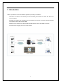
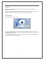
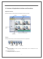
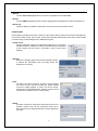
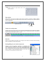
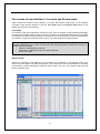
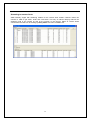
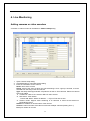
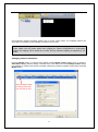
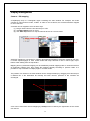
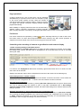
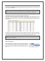
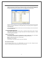
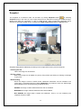
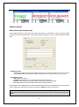
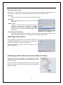
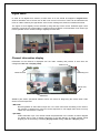
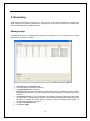
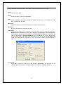
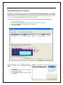
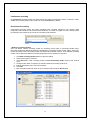
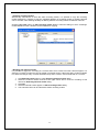
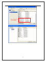
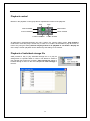
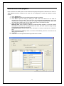
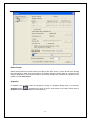
VMS User Manual About this Manual This user manual provides information on operating and managing the optimal video management software, VMS. The manual includes instructions of installation, operation and configuration of VMS as well as how to do troubleshooting. This manual contains various applications based on network knowledge. User‟s basic network knowledge may be needed to fully understand this manual. This manual is designed to deliver the optimal ways to utilize various Network Video Recorder configurations. Legal Notice The legal conditions of camera surveillance vary depending on regions. Unauthorized and inappropriate use may cause you to have penalties. Users have the responsibilities of legal operation of surveillance product. Please make sure to check your local laws before using this product. Safety notices Do not proceed with improper operation beyond the instructions in this manual to avoid damages. Please read this manual before operation and follow instructions. -2- Table of Contents 1. Introduction ......................................................................................................................................................... 5 2. Installation and Startup ....................................................................................................................................... 6 3. Overview of Application Interface and Functions ................................................................................................ 8 4. Live Monitoring .................................................................................................................................................. 13 Adding cameras or video encoders .................................................................................................................. 13 Display management ........................................................................................................................................ 16 Viewing on the secondary monitor .................................................................................................................... 20 Connection and disconnection of a camera ...................................................................................................... 21 PTZ control ....................................................................................................................................................... 21 Snapshot .......................................................................................................................................................... 24 Audio control ..................................................................................................................................................... 25 Video input color control ................................................................................................................................... 26 Indentifying sensor state and control of alarm in the tree ................................................................................. 26 Digital zoom ...................................................................................................................................................... 27 Channel information display ............................................................................................................................. 27 5. Recording .......................................................................................................................................................... 29 Storage setup ................................................................................................................................................... 29 Recording mode and schedule ......................................................................................................................... 31 Manual recording .............................................................................................................................................. 35 Recording control: on/off ................................................................................................................................... 35 Checking how recording is going on ................................................................................................................. 35 Setting recording parameters............................................................................................................................ 36 Record mode interface ..................................................................................................................................... 37 6. Search and Playback ........................................................................................................................................ 38 Search by date and time ................................................................................................................................... 38 Search by event ................................................................................................................................................ 39 Playback control ............................................................................................................................................... 40 Playback of individual storage file ..................................................................................................................... 40 Remote search and playback ........................................................................................................................... 41 Backup .............................................................................................................................................................. 42 7. Event Handling .................................................................................................................................................. 44 Event monitoring and search ............................................................................................................................ 44 Event log and search ........................................................................................................................................ 45 Event handler.................................................................................................................................................... 46 8. E-Map ............................................................................................................................................................... 51 Importing maps ................................................................................................................................................. 52 Connecting to VMS ........................................................................................................................................... 52 -3- Placing cameras onto a map ............................................................................................................................ 53 Pop-up video..................................................................................................................................................... 53 Event handling .................................................................................................................................................. 54 Configuring the object display ........................................................................................................................... 56 9. Additional Functions .......................................................................................................................................... 57 Serial data pass-through ................................................................................................................................... 57 -4- 1. Introduction VMS is a powerful IP video surveillance application providing rich features. Connect to a number of IP cameras (or video encoders) and monitor live video and audio from them in realtime. Record the streams from cameras into local storage and provide convenient search, playback and export to video clips of stored data. Monitor various events from camera and associate various actions to handle the events. Provide stream relaying service to remote clients. -5- 2. Installation and Startup Minimum system requirements The following minimum requirements should be met for normal functioning of the VMS. Operating system: Windows XP Professional, Vista Business, Server 2003, Server 2008 CPU: Intel Pentium 4 2.4GHz or higher RAM: 1GB or larger Network: Ethernet 100Mbps or higher Graphics: - Graphics memory: 128MB or larger - DirectX9.0c installed - Screen resolution: 1024x768 or larger Note: Above minimum requirements are for normal functioning with a few cameras. The requirements to support more cameras vary a lot depending on the number of channels, video resolution, framerate, bitrate etc. Please contact Marshall technical support to get the recommendation for a specific configuration for supporting a large number of cameras. -6- Installation Installation of the VMS is started by double-clicking the installation package. Please follow the instructions for installation. During the installation, the password for the administrator will be prompted. An administrator user of ID admin is created by default and the password is configured on the installation. Startup and login Login dialog comes on executing VMS. Correct user ID and password of a registered user should be entered. The dialog also provides a way to change the password of a user. The dialog for changing password will come only when User ID and Password are entered correctly. When Automatic login is checked, the VMS doesn‟t ask login in the next startup. Automatic login setting can be changed in Security setup also. -7- 3. Overview of Application Interface and Functions Application interface Application interface of VMS consists of several parts as shown in the figure. Video window Toolbar Control pane Timeline for recording status Status bar Tool bar Tool bar provides the way to invoke frequently used functions or applications. Setup Record mode Live mode Search E-map Event log Setup Opens the dialog for setup the VMS. Individual dialog can be accessed also from corresponding menu. Live mode / Record mode Changes the UI mode of the application. -8- Search Invokes True Search application for search and playback of recorded data. E-map Invokes TMAP application which provides geographical management of camera locations etc. Event log Opens a dialog for realtime monitoring of events and searching stored events. Control pane Control panes provides most of the controls for the VMS including camera connections management, PTZ control, audio control, color control. It also shows storage status briefly. Each pane can be hidden or shown using corresponding menu in View menu group. Camera tree Shows registered cameras and provides operations for connection and disconnection. Statuses of sensors and alarm devices attached to the camera are also shown. It provides a way to start record instantly. Storage Shows the storage status and recorded duration briefly. It collects the information from the disks which are selected for recording. PTZ Provides PTZ control interface. Circular control provides full control for pan and tilt including the speed. Speed control the dialog applies to zoom and focus control. Preset also can be selected here. Further controls of PTZ cameras are available on PTZ control dialog. Audio Provides controls for audio send on/off and mute for PC speaker. Volume also can be controlled. Audio file in wave format can be played toward the camera instead of live input. -9- Color Provides controls for input video color of the selected camera. Video window Video window is the area for display video from the cameras. It consists of display units(DU, hereafter). The toolbar above the video window provides ways to change the mode of video window to various configurations. Multi-screen mode PTZ Snapshot Full screen Timeline for recording status Timeline shows the recording status of a selected camera. Detailed view can be obtained by changing the scale of the timeline using + button or – button. While it is updated periodically, it is possible to update manually by pressing the button or refresh. Status bar Status bar shows additional information such as login ID, the number of currently connected viewing clients, and statistics for serial TX/RX activity. Showing/Hiding the user interface components Visibility of each user interface component is controllable using corresponding menu in View menu. When some of the features are not used, corresponding components can be hidden. Sensor/Alarm nodes menu controls whether sensor and alarm nodes in the tree are to be shown or hidden. In case sensor/alarm devices are not used, more concise tree can be obtained by hiding the nodes. -10- Two modes of user interface: Live mode and Record mode VMS provides two modes of user interface, Live mode and Record mode, which can be selected according to the specific situation in the site. Live mode button and Record mode button in the toolbar are used for mode switching. Live mode Live mode is used where interactive monitoring of live video is required. As the decoding and display of video takes essential CPU load, the number of cameras to be viewed simultaneously can be limited according to the video encoding settings of cameras and PC‟s performance. In terms of functionality, Live mode is a super set of Record mode. That is, Live mode supports recording function. Note: If the graphics mode of the PC is not configured to support video display in Live mode, “Display initialization error” comes on video area. The following essential condition for running Live mode should be checked: - Minimum 128MB graphics memory - DirectX9.0c installed and maximum H/W acceleration - 32-bit color mode Record mode When live monitoring in the VMS PC is not essential, it is preferable to use Record mode. As it doesn‟t use CPU load for decoding and display, more cameras can be accommodated for recording and streaming. Another advantage of Record mode is that it can run in any display mode with any kinds of graphics cards. -11- Streaming to remote clients VMS internally equips with streaming module for the remote client viewers. Remote clients can connect to VMS to get video, audio and event data. This way of indirect relaying reduces the streaming load of the camera as well as the network to the camera. Status of remote clients connected to the VMS can be viewing by Relay status sub menu of View menu. -12- 4. Live Monitoring Adding cameras or video encoders A camera or video encoder can be added on Camera setup dialog. 1. Open Camera setup dialog. 2. Click Add button to open Add camera dialog 3. Enter the information for the camera Name: name of the camera Group: name of the group to which the camera belongs. Once a group is entered, it can be selected from the entry of the next camera. Type: Currently VMS supports MEI VS products as well as TOA cameras. Select the camera type to be added. 1. TCAM/TCS : MEI VS IP camera or MEI VS video servers 2. Netcansee : TOA camera - Please add “toa://” before IP address → Ex) toa://192.168.10.180 3. Generic RTSP: Support video streaming of IP cameras or video servers based on RTSP/RTP protocol. Address: IP address or domain name of the camera Channel: channel number if the video encoder has multiple channels (starting from 1) Port: port number to connect -13- Protocol: protocol for streaming video/audio data Audio: uncheck when audio will not be used PTZ: check if PTZ control for the camera is to be used Login/Password: login ID and password of the camera Relay name: name of the streaming server when the VMS is connecting to the specified camera by way of streaming server Relay address: address of the streaming server Relay port: port of the streaming server (default: 2222) Relay login: login ID of the streaming server (default: admin) Relay password: password of the streaming server (default: 1234) User info1~3: additional information to be described for user‟s needs. 4. Click OK. It is possible to detect the cameras, video encoders or video decoders in the same LAN using IP Discovery function. 1. Click IP Discovery button on Camera setup dialog 2. Select a device to add on IP Discovery dialog 3. Enter additional information on Add camera dialog Quick viewing of added camera Once a camera is added, it will come on the tree and connected if it is reachable. The camera node will be in grey color if it is connected. The video from the camera will not be displayed on video window until the camera is explicitly mapped to a DU(display unit). The simplest way of mapping a camera to a DU is to use automatic mapping function. 1. Click the right button of the mouse on any position of the video window. 2. Select Auto map menu 3. All cameras in the tree will be mapped to DUs sequentially(left-to-right, top-to-bottom). If there are more cameras than a page of the screen mode can accommodate, more pages will be created automatically. -14- One automatic mapping operation applies only to current screen mode. The mapping needs to be done again in manually or automatically in another screen mode. Note: Cameras are mapped to DUs automatically without explicit mapping operation in 1x1 screen mode. While user may prefer his/her own mapping for various configurations in multi-display modes, the mapping can be limited in1x1 mode. So only automatic mapping is supported in 1x1 mode. Changing camera information Pressing Modify button on Camera setup dialog invokes Modify camera dialog which is similar to Add camera dialog. Double clicking a camera entry in the table also invokes Modify camera dialog. It is possible to modify some entries of multiple cameras by selecting multiple entries before pressing Modify button. Select multiple entries to change more than one cameras at once -15- Display management Camera – DU mapping A DU(Display Unit) is a rectangular region consisting the video window. For example, 2x2 mode consists of 4 DUs and 4x4 mode, 16 DUs. In order to view a camera, the camera should be mapped to one of the DUs. A camera can be mapped to a DU in three ways. (1) Drag a camera from the tree and drop on a DU. (2) Use Map camera menu on a DU. (3) Use Auto map function to map all cameras to DUs in a screen mode. Drag & drop Use Map camera menu on a DU Automatic mapping is convenient for mapping all registered cameras to all screen modes at one click. It creates required pages in each screen mode and maps cameras to DUs in left-to-right, top-tobottom order starting from the top-left DU. Mapping done by automatic mapping can be modified by manual mappings later. It would be useful to do automatic mapping first, then modify the mapping partially according to specific needs. It is possible to map a camera to multiple pages in a screen mode. The position of a camera in the video window can be changed instantly by dragging a DU and drop on a different DU. If the destination DU already has other camera, positions of two cameras are exchanged. Drag and drop for position change A DU can be freed from camera mapping by Unmap menu invoked by the right button of the mouse over the DU. -16- Page operations A page is defined as a set of DUs which can be displayed simultaneously in a specific screen mode. For example, a page in 4x4 screen mode contains 16 DUs. When the number of cameras is larger than the number of DUs in a page, more than one pages are required. Automatic mapping creates required pages automatically. More flexibility in mapping cameras to DUs can be achieved by allowing creation, renaming, repositioning of pages manually. Menu for page operation is invoked by clicking the right button of the mouse over the page title part. Full Screen Full Screen mode will be operated by clicking button. Generally ESC key is used to return from full screen mode. For sites where keyboard is not used, returning only with mouse operation is supported. Press the wheel of the mouse for returning from full screen mode. Controlling video encoding of cameras to get effective multi-channel display Video encoding setting of individual camera Video encoding tab of Display setup allows the setting of video encoding of a camera. As it modifies the setting of the camera, the effect will be propagated to all connected clients as well as recorded data by the VMS. Right button click on a value It is useful to use Propagate to all function invoked by right mouse button click on a value to set the same value to all cameras. Settings are retrieved, kept to local configuration file and set to the camera in the following way. Initial settings when a camera is added When a camera is added, settings are read from the camera on the first connection. These values are saved to the local configuration file. „-„ is shown until it succeeds in the first connection. Get from camera operation Settings can be read from the camera by pressing Get from cameras button at any time. When there are a lot of cameras and/or the network is poor, it may take considerable time. If Get settings whenever Display setup is opened is checked, the VMS reads settings from cameras whenever the dialog is opened. Applying the settings to camera and saving to the configuration file If Send modified settings only is checked, only settings changed manually or by Get from cameras since opening the dialog are applied to the cameras and saved to the configuration file on clicking OK or Apply. Otherwise all settings in the table are applied unconditionally. It is recommended to check this setting in order to apply the settings only when necessary. -17- It is useful to use Propagate to all function invoked by right mouse button click on a value to set the same value to all cameras. Note: When the display and recording are configured to use the same stream(primary or secondary), change of video encoding setting in one setup invalidates the settings in the other setup. It is preferable to configure in only one setup when the same stream is used for both. Automatic control of video encoding for various screen modes Due to the load by video encoding, it is not possible to view many HD video simultaneously. On the other hand, it is not so meaningful to view HD video in a small display unit in NxN screen mode. As a compromise, VMS provides a way to control video encoding setting automatically according to current screen mode. This feature is more useful if the camera or encoder supports dual stream encoding. One stream can be configured with fixed setting to get consistent recording quality, while the other can be controlled dynamically according to the screen mode to get smooth display with affordable CPU load. Note: Automatic control is useful only when Decode visible channel only setting is ON. If the setting is OFF, all channels are decoded regardless of the screen mode and CPU loads can be almost the same in any modes. Video on/off control Video streaming from a camera can be turned off using the menu on the camera node of the tree or DU. Event handler provides a way to turn video on automatically on selected events. Video on/off menu together with this feature allows event-based viewing of video. -18- Additional settings for video display Etc tab of Display setup contains additional settings related with video viewing. Image for unassigned window Normally DU displays black screen when no camera is mapped. Customized image can be displayed by this setting. Decode visible channels only When set, the VMS don‟t decode invisible channels. For instance, max 4 channels are decoded in 2x2 screen mode. When the screen mode is changed to view channels which are not visible in current mode, it will take a few seconds to get video for the channels which are in invisible state in current mode. If the performance of the PC allows decoding of all channels simultaneously, quicker video display can be achieved by disabling this setting. Stop video display while Search application is running When checked, the VMS stops displaying video if True Search application is running. This is to reduce CPU load for efficient running of search application. Keep aspect ratio (ALT+F5) When checked, video display in a DU keeps the width-height ratio of the encoded stream instead of scaling to fit to the DU and remaining part comes in black. -19- Keep aspect ratio OFF Keep aspect ratio ON Deinterlacing Select the deinterlacing method. Display buffer Set the number of frames before decoding and display. Larger value results in more smooth display while the latency increases. Sequencing When enabled, pages in a screen mode are displayed in turn in a specified interval. Viewing on the secondary monitor VMS allows opening of another video window which can be moved to the secondary monitor if it is supported in the PC. The extra video window is called Secondary monitor view. The secondary monitor view can be opened using Secondary monitor menu in TVMS menu. The secondary monitor view has the GUI similar to Live mode of main GUI, but items which have nothing to do with video display are omitted. A camera can be mapped to a DU of the secondary monitor using the menu on the DU. One camera can be mapped to both to the primary monitor(main GUI in Live mode) and to the secondary monitor view. Dragging a camera from the tree in main GUI to the secondary monitor is not allowed. -20- Connection and disconnection of a camera How to connect or disconnect A camera can be connected or disconnected with one the following ways: (1) Menu on the camera node of the tree (2) Menu on the DU (3) Checkbox on Camera setup dialog The menu on a group node can be used to change the connection states of all cameras in the group in a single operation. Camera icons for connection states Depending on the connection state of a camera, the icon in the tree comes in different color. A DU displays current state in text over black or blue window. PTZ control PTZ control for a camera is enabled only when Use PTZ setting is checked on adding a camera in Camera setup. PTZ control on the control pane PTZ tab on the control pane provides casual functions in camera PTZ control: pan/tilt/zoom/focus and preset selection. Full controls are available on the PTZ dialog invoked by PTZ button on the toolbar above the video window. Drag the button Pan/tilt Small button inside the circular plate can be dragged to move the camera to a desired location. The distance from the center or the circle determines the speed of pan and/or tilt operation. Another way is to click the specific position in the circular plate. Then, the button will be moved to that position, which has the same effect of dragging the button. Zoom/focus Zoom and focus are triggered by pressing (-) or (+) button. Focus provides auto-focus function by the button with car sign inside. The speed of zoom and focus operation is controlled by setting the Speed slider. PTZ control dialog PTZ control dialog is invoked by button in the toolbar above the video window. The button is enabled only when currently selected camera is configured as having PTZ capability. -21- In addition to the PTZ control tab available on the control pane, PTZ control dialog provide more functionality. Some functions are effective only when the camera connected to the video encoder supports those features. For example, some cameras don‟t support power, wiper or light control. Preset configuration Although the maximum number of preset entries is 256, actual number of preset entries varies depending on the models. Preset function can be used in the following way. 1. 2. 3. 4. Control PTZ to make the camera view a wanted scene. Select the preset number to assign to the view. Press Set button. Press Edit button to invoke a dialog where the preset name can be edited. To make the camera view a selected preset location, select a preset entry and press Go button. Clear button releases the preset setting of an entry. Tour configuration and selection A tour is the function to visit preset locations sequentially. Tour groups which are selected sets of preset entries can be configured in the dialog invoked by Config button. -22- Multiple tour groups can be defined by selecting the entries from the preset lists arbitrarily. Add button and Edit button invoke a dialog of the same shape where preset entries constituting a tour group can be selected. A preset entry can come multiple times in a tour group. Dwell time which is the time to view a specific preset location before moving to the next preset location is 5 seconds. Dwell time for each preset entry of a tour group can be configured on Tour setup dialog. A tour is operated by selecting a combo entry in the PTZ control dialog. Tour can be turned off by selecting none entry. Camera power/wiper/light control Power, Wiper, Light buttons can be used for controlling camera power, wiper, and light respectively. These functions are mostly used when the cameras connected to a video encoder supports the functions. Setup of analog camera Some analog cameras provide the configuration in terms of OSD menu. PTZ control dialog provides buttons and controls to configure the camera using the OSD menu. Menu: to enable the OSD menu for camera setup Enter, Esc: menu operation Circular button on the plate: direction control menu browsing On-screen PTZ control When On-screen control mode is set to PTZ control in the menu of the DU, clicking left mouse button on the DU triggers the pan/tilt operation to move the direction. -23- Snapshot The snapshot of a channel‟s video can be taken by clicking Snapshot button or selecting Snapshot menu in the menu of a DU. Image format can be selected on saving the snapshot image. Bitmap and JPEG are supported. In case of JPEG format, JPEG compression parameter which determines the image quality can be configured by JPEG compression setting in General setup. Mosaic processed Snapshot dialog allows additional processing on the image before saving it as an image file. Inserting the title Title of the image can be inserted. Privacy control Parts of the image can be hidden for privacy using mosaic processing or drawing a rectangle in grey color. Watermarking When the image is saved in JPEG format, watermark information can be inserted to the image data. A customized program called JPEGViewer is provided to check if a JPEG image was modified since it was saved using snapshot function. SIGNED: the image contains watermark and it was not modified. MODIFIED: the image contains watermark and it was modified. NOT SIGNED: the image doesn‟t contain the watermark. That is, it is not created by the snapshot function of VMS. -24- Audio control Audio send mode and play mode As the VMS connects to more than one camera generally, it is necessary to have the way to select cameras for audio communication. Audio setup provides settings for how to send and receive audio data. Talk(send) mode Determine to which camera(s) the audio data from PC‟s audio input device or a wave is sent. To selected only mode will be used when audio stream is to be done to only one camera. Listen(play) mode Off: audio is turned off. Selected: audio data from currently selected camera are played. Visible: audio data from currently visible cameras are mixed and played. All: audio data from all connected cameras are mixed and played. It is possible to send wave file to the camera instead of live input from audio device. Up to 4 wave files can be registered. Actual file to be sent is selected on Audio tab of the control pane. Note: Listen(play) mode setting has no relationship with recording. Audio data are received regardless of this setting if audio recording is enabled and the camera is configured to send audio data. -25- Audio talk/output control Audio tab of the control pane provides interactive control of audio talk mode and audio output to PC‟s output device. A wave file can be selected for playback to the server instead of live input. PC input When the mic button is in OFF state, audio data sending stops. PC output When the speaker button is in OFF state, audio data play stops. Audio source The source of audio data to be sent to the camera is selected. If a wave file is selected, it is played repeatedly until audio source is changed to Live(Mic). Sending a wave file is also disabled if PC input control is turned off. Audio/video synchronization Audio/video synchronization is supported. The synchronization is supported by default. It can be turned off or parameters can be configured on Audio setup page of TVMS. Video input color control Color properties of input video of the selected camera are configured on Video tab of the control pane. Some cameras or encoders don‟t support control of some properties. Settings changed using these controls are effective on the camera‟s web setup. Indentifying sensor state and control of alarm in the tree When a sensor device connected to a camera changes its state, corresponding event is generated and it changes the icon in the tree to yellow color. The menu Change On/Off state which comes by clicking the right button of the mouse over an alarm node allows the control of the alarm(relay) state. -26- Digital zoom In order to use digital zoom function, mouse clicks on a DU should be mapped to Digital zoom. Another alternative use of mouse click on DU is On-screen PTZ control. These can be selected in the menu of a DU invoked by the right button of the mouse. Settings are saved for individual channels. The region to zoom digitally can be selected by drag and drop of the mouse. Selected region come enlarged. It goes back to original state by clicking mouse‟ left button in zoomed state. Four arrow keys in the keyboard can be used for shifting in digitally zoomed state. Channel information display Information on the channel is displayed over the video. Visibility and position of each item are configured on Etc tab of Display setup. Motion icon Channel name Recording icon Server time Statistics Statistics part shows operational statistics which are useful for diagnosing the reason when video doesn‟t come as expected. RX=1445 Receiving bitrate of video data in kbps unit. If it is much lower than the setting in the camera, the network or performance of the PC can be suspected. It can happen also when too many clients are connected to a camera. fps=24(0) Video framerate in fps. The number inside the parenthesis is the number of frames skipped for display due to lack of display resources or too late delivery of frames caused. Small skipping can be avoided by increasing Display buffer setting at Etc tab of Display setup. -27- Buf=3 Number of frames in the buffer. This value is approximately proportional to Display buffer setting. (0, 56) Audio TX bitrate and RX bitrate in kbps. In case of G.711, the range of normal value is 50 ~ 70. -28- 5. Recording VMS supports simultaneous recording of a lot of cameras to the storage consisting of storage files. Each storage file is optimally structures for supporting long pre-event and post-event recording and synchronized playback of multiple channels. Storage setup The storage needs to be configured first to make the recording work. The only thing to do is to select the drives to be used for recording. 1. Open Storage tab of Record setup 2. Check the drive to be used for recording 3. Adjust Reserved size if necessary Reserved size is the amount of space to be left without writing record data for other purposes like keeping backup data. If the drive will be fully used for recording, this setting need not be touched. 4. Click Advanced button to open Advanced setup dialog if necessary. Advanced setup dialog provides a way to change the interval and/or size of storage file generation. Generally it is not necessary to change the default setting. However, it may be necessary if the pattern of recorded data generation is unusual. 5. Configure On disk full action. 6. Click OK or Apply -29- Storage tab also shows full information on the disks and recorded duration for each disk. Total Used Free Total size of the drive Amount of space contained recorded data Space available for recording. If this size is smaller than the size of the storage file. VMS doesn‟t write data to the disk. Reserved Amount of space to be left without writing record data for other purposes. Duration Duration represented by the data in the disk. Advanced Advanced settings dialog is to configure the interval and the size of a storage file generation. Bitrates section of the dialog is just for easy calculation of total bitrates of all channels. When the total bitrate is calculated or configured manually by Manual setting, it recommends the size of a storage file in Recommended file size to the amount for 1 hour duration. This recommended value or any other value preferred by user can be set on File Size to set section. The VMS generates a new file when one of these two conditions, interval and size, is met. On disk full Action when all selected drives become full. Generally Overwrite is selected to recycle the storage. Other actions such as sending E-mail can be configured by Event handler. -30- Recording mode and schedule Three kinds of recording modes are supported: Continuous, Event-based, Manual. Event-based recording allows user-defined combination of various types of events. While Manual recording works independently from the schedule setting, Continuous recording and Event-based recording can be set to 1 hour unit on the schedule table of 1 week x 24 hour format. Recording mode and schedule of a camera can be configured on Record tab of Record setup. 1. 2. 3. 4. Click a camera to configure. Select the recording mode in the combo at the bottom part of the dialog. Fill the schedule table by dragging or click the mouse. Click OK or Apply. The last row, H, in the schedule table is for holidays. Holidays can be configured in General setup. 1. 2. 3. 4. Select a day. Click Add at the bottom part of the dialog. Edit the description to Check Annual setting if the day is fixed every year. -31- Continuous recording In Continuous recording mode, the VMS records the channel continuously. When a camera is newly added, the recording mode of the camera is set to Continuous by default. Event-based recording Event-based recording works only when specified event condition happens in the camera. Most frequently used events are sensor and motion detection. For these two types of event, VMS provides pre-defined event modes in the combo for recording mode selection. Defining recording modes User can define various recording modes by combining event types in extremely flexible ways. Recording modes are defined by arbitrary combinations of primitive events: sensor, alarm, video loss, motion and serial event. Recording modes are defined for individual camera. Thus different recording modes can be defined for different cameras depending on the situations in the sites. 1. Click Edit recording modes button to open the dialog. 2. Select event types to combine. 3. Click Add button. New recording mode is added Recording modes section with another color. 4. Change mode name if necessary to describe what the recording mode is for. 5. Edit the description of the event if necessary. 6. Click OK. 7. New recording mode will come on the recording mode combo on Record tab. -32- Copying recording modes When many cameras are to have the same recording modes, it is possible to copy the recording modes defined for a camera. In this way, repeated definition of recording modes to multiple cameras can be avoided, while allowing flexibility of defining different recording modes for different cameras. Clicking Copy from button on Edit recording modes dialog invokes the dialog on which recordings modes defined for other cameras can be selected for copying. Working with external events It is possible to trigger the recording of a camera when some events from other camera happen. For example, recording of camera A can be started if camera B goes to video-loss state. Another example is to start recording of many cameras simultaneously when a sensor event is detected on a camera. 1. Click External events button to open Selecting external events dialog. 2. Select the external camera and the event types which will be used for recording of this camera on Selecting external events dialog 3. Click OK. 4. Selected external events appear on Edit recording modes dialog. 5. The external events can be selected to define recording modes. -33- External events from camera Garage -34- Manual recording Manual recording is to start recording of a camera instantly in a specific situation without setting recording mode and schedule. The menu for starting or stopping manual recording is available on the menu on the camera icon of the tree. Manual recording works independently from recording mode and schedule. When manual recording is turned off, the recording mode setting with the schedule becomes effective again. Recording control: on/off Recording of a channel can be turned on or off with keeping the recording mode and schedule untouched with the check box at the first column in Record tab. This setting doesn‟t affect manual recording which works unconditionally. Checking how recording is going on A number of ways are provided to check if the recording is going on. Storage tab Storage tab of the control pane shows storage status and recorded duration briefly. When the recording is going on the newest time of the duration is periodically updated. Information such as the amount and duration in the tab is obtained only from the drives selected on Storage setup. Data in deselected drives are not included. Timeline Timeline shows the recorded status of the selected channel. More detailed view of the status can be obtained by adjusting the scale of the time using periodically update, it is possible to refresh any time using -35- and button button. Although timeline is Recording icon in Live mode and status in Record mode If display of recording icon is checked in Display setup, the recording icon mode. comes on the DU in Live In Record mode, Status field shows the connection state as well as recording status. Search and playback with True Search Full operations of search and playback on all channels are possible by invoking True Search application with Search button on the toolbar. Setting recording parameters Record tab of Record setup contains various parameters which can affect the stream to be recorded. As it is not possible to change the properties of the video stream such as resolution and framerate once the stream is encoded, the settings on Record tab changes the settings in the cameras. As a result, the effect of settings in Record tab is propagated to all clients as well as the video display in Live mode. Changes settings in the camera Record Check to turn on the recording. Manual recording works regardless of this setting. Pre Post Pre-event recording duration in seconds. Post-event recording duration in seconds. Stream Select the stream to record. Single stream camera shows Primary entry only. Preference ~ I-Frame Video encoding parameters of the camera. Refer the user manual of the camera or the video encoder. Audio Check to record audio stream together. Parameters of all cameras in the grid can be changed at once using Propagate to all function invoked by right button click of the mouse over an entry. -36- Note: Allowing video encoding settings in the VMS is useful for convenient settings of multiple cameras without opening web-based setup pages. However, it should be used carefully as it modifies encoding setting of the camera. This means that the setting in Display setup can be invalidated by the setting in Record setup if both are using the same stream. In case of dual stream camera, it is ideal to use one stream for display and the other for recording. Then, settings in two setups don‟t affect each other. Record mode interface If viewing cameras continuously is not essential, running the VMS in Record mode is preferable. In Record mode CPU load is much lower as decoding and display are not performed. The mode also shows more detailed statistics on the recording status. Another advantage is that it can run on any kinds of graphics cards. -37- 6. Search and Playback Search and playback of recorded data are supported in a separate application: True Search. True Search is invoked by clicking Search button on the toolbar. Calendar Tree Playback control Timeline Search by date and time A scene of interest can be found by selecting date, camera and the time. 1. Click a day in the calendar. Days with recorded data are marked with red color. Month can be changed by clicking arrow buttons in the calendar. When a day is clicked, the tree is updated with the channel having data on the day. When there are a large number of cameras, loading the tree can take some time. 2. Select the channels to search. Up to 16 channels can be selected. Only one audio channel can be selected at a time. 3. When channels are selected, the timeline will be updated to show recorded status of the channels. 4. Move the current position bar in the timeline to a position to play. 5. Press Play button. Instead of moving current time in playback using the position bar, it is possible to set a specific time in the dialog invoked by double clicking the current time display. The tooltip appears when the mouse is over the current time display. -38- Current time bar is moved dialog. to the time specified in the The scale of the timeline can be changed by button and 24hours, 12hours, 6hours, 3hours, and 1hour, are supported. button. Five different scales, Search by event One or more channels recorded invoked by Event search by a specific event can be searched in Event search dialog button 1. 2. 3. 4. 5. 6. Select the camera to search. All camera can be included by selecting --For All Servers --. Specify the duration to search. Select the types of events. Select event status: On, Off or All for both type. Click Search button. Play the channels recorded by the event either by double clicking the entry or by selecting an entry and click Play button. 7. Event search dialog will disappear and playback of the channels will be started from the event time. Channel selection in the tree is also updated automatically with the channels recorded by the event. -39- Playback control Buttons in the playback control group allows sophisticated control of the playback. Play Stop Fast backward Fast forward 10 sec backward 10 sec forward 1 frame backward 1 frame forward All playbacks in backward direction play only I frames. So, jumping effect comes. Fast forward in multi-screen mode also plays I frames only. In case of 1x1 mode, it is selectable to play all frames or I frames only using the setting Decode only key frames in FF playback in 1x1 mode in Display tab of the setup. Smooth playback can be obtained by this setting is not checked. Playback of individual storage file VMS provides a way to play individual storage file or to play all storage files in a specific folder or a drive. This feature is useful to play storage files copied as a backup. Open storage file dialog is invoked through a menu on the root node(named Local storage) of the tree. -40- Remote search and playback Data recorded in the VMS system can be searched and played through the network from a client PC. True Search should be installed in the client PC and configured to access the storage is remote system. 1. Open Setup dialog 2. Select Remote mode to access VMS system through the network 3. Click Add to open the dialog for adding an VMS. Name and address of the VMS are specified. Port 2121 is used for TCP connection for remote search and playback. If port, login or password is modified, it should match the setting in Remote Search Server. More than one VMS can be added, but only one VMS system can be connected at a time. 4. Other settings can be configured optionally. Buffering time: set the amount of data to be buffered before playback. In case the network bandwidth is lower than the encoding bitrate of the video, this value should be large enough to avoid frequent stopping and buffering. Command timeout: set the timeout in the interaction. It can be increased of the network is poor. Auto reconnect on backup: check to reconnect automatically when the connection is lost during long term backup 5. Click OK 6. It will connect to the specified VMS and get data from the VMS. -41- In order for remote search and playback to work, Remote Search Server application should be running the in the VMS system. It is automatically started by starting VMS. However it is possible to start manually using Start Remote Search Server menu. Remote Search Server appears as a tray icon at the bottom part of the Windows. User interface of Remote Search Server can be opened by double clicking the tray icon. The user interface allows modification of default settings. It also shows currently connected clients. Note: True Search may fail to connect to VMS system with the following reasons: - VMS system is actually unreachable in the network - VMS system is reachable but it is protected by the firewall. Port 2121 should be open. - Remote Search Server application is not running in the VMS system, or it is configured with different setting: port, login, password Backup Backup provides a way to copy a duration of recorded data to a file. Two formats of backup files are supported: AVI file and Native format. The same backup dialog invoked by Backup button used, and the format is selected in the dialog. is AVI format AVI format is used to use casual media player such as Window Media Player, GOM Player, or VLC Player for playback of the backup file. As AVI doesn‟t allow multi-channel video streams, a backup for each channel needs to be taken separately. 1. 2. 3. 4. 5. 6. 7. 8. 9. Select a camera to make backup. Select Backup setting to AVI. Specify the duration. Check Include audio if audio is to be included. Click Refresh button to estimate the size of the backup file. This can take significant time if the duration of the backup is long. This step is optional. In case of remote access to the VMS system, Remote backup speed can be additionally configured to limit the bitrate of backup to share the network bandwidth with others. Configure the name of the backup file. Click Start Backup button. Progress will be shown. When multiple channels are selected, the VMS makes the backup for each channel one by one. The names of the backup files are automatically generated in this case. -42- Native format Native format means the format used for recording in the VMS. That is., it is the format of the storage files generated by VMS. Except that backup of multiple channels can be taken to a single file, the usage is basically the same as the backup in AVI format. Storage files created by the backup can be played only with True Search. Snapshot A snapshot can be taken while the playback is going on. Snapshot dialog which is invoked by Snapshot button is basically the same as that in Live mode of the VMS. Please refer to Snapshot section of the chapter for Live monitoring. -43- 7. Event Handling Event monitoring and search Events monitored in the VMS are classified into two categories: camera events and VMS(or local) events. Camera events Camera events come from cameras or video encoders when specific situations happen. Camera event Sensor on/off Description Delivered when the sensor device attached to sensor(DI) port of a camera changes its state. Alarm on/off Delivered when the alarm(DO) port of a camera changes its state. Motion on/off Delivered when a camera detects motion in the scene or the motion disappears. Videoloss on/off Delivered when a camera losses video input signal. Since video input module tightly assembled with other parts in IP camera, this event is rare in IP camera. On the other hand, this can happen due to disconnection of video cable or fault in analog camera in case of a video encoder. VMS events VMS events represent some situations in the VMS which need to be logged for interpretation of recorded status. VMS events are sometimes called as Local events. VMS event Description VMS started Startup and termination of the VMS generate the events. Forced VMS terminated killing of VMS process or accidental termination due to error doesn‟t generated VMS terminated. So these can be used to check whether the VMS was terminated due to error or not. Camera connected Generated when the connection to a camera is established or lost Camera disconnected respectively. These are useful to check if there have been failure in the network or the camera. Config changed Generated when the configuration of the VMS is changed. -44- How events are monitored Camera events are monitors in more than one ways. Sensor event an Alarm events change the states of icons in the camera tree. Motion icon in a DU reflects the motion detection state of a camera. DU also display Videoloss message when the camera loses video signal. Events are monitored in a dialog, which also provides search of stored events. Event log menu or Event search menu invokes the dialog with corresponding tab opened. When specific actions need to be executed when an event happens, Event handler can be configured. Event log and search Event log menu invokes a dialog where both camera events and VMS events can be monitored in realtime. This dialog shows the events happened only after it is opened. Event types can be selected to include the events of interest only. -45- Event search menu invokes a dialog where events in the storage can be searched. Event handler VMS provides versatile event handler with which various actions for the events generated at the VMS as well as from the cameras can be associated in a very flexible way. Each action can have independent schedule which allows the control of action dispatch according to days and time. An event handler is an association between a specific event from a camera or the VMS and a specific action. Camera-A‟s sensor 1 ON Event handler 1 Camera-A‟s alarm 1 ON Schedule-A Camera-B‟s motion ON Event handler 2 Goto camera-B‟s PTZ #2 Schedule-A VMS disk full Event handler 3 Send E-mail to the operator Schedule-B A schedule which controls when to trigger the action is defined independently and associated to an event handler arbitrarily. As a result it is possible to use the same schedule for multiple event handlers. -46- Actions for events Various actions can be associated to the events from cameras or the VMS itself. Action Operation Parameters A popup window to display the video from the Duration of the popup camera comes. window display Blink video channel Blink the border of the DU in red color. Duration of the blinking Change screen mode The screen mode is changed to show the to 1x1 camera in 1x1 mode. Video on/off control Control video-on/off mode of the camera. Play wave file Play a specified wave file. Popup video window -Wave file to play -Once or repeat Send wave file to camera Audio mute on/off Send a specified wave file to the camera to -Wave file to play play to the camera‟s audio output port -Once or repeat Control audio playing on PC. It controls PC Duration and on/off control Output control on Audio tab of main UI. Camera alarm control Turn on or off a specific alarm of the camera Duration and on/off Goto PTZ preset Control the camera to view a specified preset Preset item position Activate PTZ tour Activate a specific PTZ tour configured at PTZ Tour item control dialog Send events to TMAP Send event to trigger an action in TMAP application Send E-mail Send E-mail to the operator E-mail title and text Event handler dialog Event handler dialog is invoked by Event handler submenu of Event menu group. The dialog shows currently configured event handlers for each camera briefly. By clicking an event source, clicking a specific event handler for that event source, it is possible to view detailed relationship between the events and actions. -47- Creating an event handler An event handler for an event source is created in the dialog invoked by Add button on Event handler dialog. 1. Choose events for which actions are to be associated. Multiple events can be selected to trigger the action on any of selected events. 2. Choose one or more actions. 3. Edit the name of the event handler. 4. Configure the parameters for events. The state of an event(on or off) to trigger the action is selected. Mostly on is configured to make the action happen on the generation of the event. 5. Configure the parameters for actions. Parameters for actions are specific to each action. Most common parameter is the duration in which the action is to be continued. The following shows an example of the dialog for configuring action parameters. It configures whether audio mute of playing on PC is turned on/off and the duration. By selecting Continuous item in Dwell time, it is possible to make the mute on/off effective until user changes the setting on Audio tab of main UI manually. -48- 6. Select the schedule to be used for this action. The action is triggered only when the schedule is configured to On state at the time when the event is generated. If Use schedule is not checked, the action happens without checking the schedule. 7. Click OK button. Click blue event/action to configure parameters Adding event handlers by copying one from other camera If events from many cameras are going to be handled in the same way, it would be boring to define the same event handler for each camera. For example, all cameras can be configured to play an wave file when any of the sensors in the camera detect the change of the state. The VMS allows copying event handlers from those defined for other cameras. -49- Defining schedules The schedules to be associated with event handlers are created independently from event handlers. Then a schedule is selected when an event handler is created or modified. This allows flexible association between event handlers and schedules; One schedule can be shared among many event handlers or each event handler can have different schedules. A schedule is created in the following steps. 1. 2. 3. 4. Edit the name of the schedule to create. Click Add button. Configure the weekly(+ holiday) schedule table by dragging and/or clicking mouse. Click OK or Apply button. -50- 8. E-Map E-Map(Electronic-Map) functions is supported in a separate application: TMAP. TMAP is invoked by clicking TMAP button on the toolbar. TMAP TMAP provides the following functions. Displays image-based maps and allows placements of cameras on specific positions. Displays a camera‟s video manually or in a event-driven way. Provides various actions such as marking a camera on receiving events from a camera. Two-way audio communication with a camera. -51- Importing maps The first step to use TMAP is to import map images. Maps of Bitmap or JPEG format can be imported in the dialog invoked by Map->Add a map menu. 1. Choose an image of Bitmap or JPEG format. It is recommended to use the image whose size is similar to that of map area of TMAP. 2. Enter the name for the map. 3. Click OK button. Added maps appear on the Map list of TMAP. Map image display area of TMAP displays the map selected by clicking the mouse on the list. A large area can be divided into multiple regions(maps). Or it is also useful to import maps of different scale for macro view of the area as well as detailed view. Connecting to VMS TMAP is designed to operate with one or more VMSs or NVRs. That is, it doesn‟t work alone. TMAP gets the camera list by connecting to an VMS. 1. Invoke Add NVR dialog using Camera->Add NVR menu. 2. Enter the information for the VMS or NVR to connect. Currently the port is fixed to 2220. 3. Click OK button. 4. More than one VMS or NVRs can be added for sharing TMAP among multiple VMSs NVRs. Added VMSs and their cameras come on Camera List part. VMS node and camera node show connection state using the color: Grey Violet Blue Connection to the VMS is disconnected by user. The menu on the VMS node provides menus for connection and disconnection. It is in „Trying connection‟ state to the VMS. TMAP is connected to the VMS. -52- Placing cameras onto a map A camera can be placed on a map by dragging and dropping a camera node in the tree. The location of the name tag(yellow rectangle) can be adjusted after placing the camera. Drag and drop A camera on the map can be deleted either with the context menu on the camera icon on the map or with the context menu on the camera node of the tree. Pop-up video Pop-up video for a camera on the map can be opened with Show video menu on the icon. Double clicking the camera icon has the same effect. Pop-up video also can be opened due to event handling function. -53- Event handling TMAP has its own event handler which maps an event to one or more actions. Sensor, motion and video loss events can be handled. The following dialog which is invoked by Event->Event Setup menu shows how events are mapped to actions and how the parameters for actions are specified. Highlight camera node Blinking red circle is displayed on the camera icon on the map. It disappears if user clicks the node or the action duration expires. Pop-up video window Pop-up video is displayed on the map. Sound effect Wave file or Windows beep sound is played. -54- Event window display and logging Events are displayed on Event Window at the bottom of TMAP GUI and logged to a file for searching later. Automatic enabling of audio output If audio output (to PC) is turned off, the event turns on the audio output. Change active channel Active channel is changed to the channel where the event happened. Event search Event log dialog is invoked by Event->Event Log menu. It allows searching of events with various conditions. TMAP stores events on its own way independently from VMS‟s event logging. -55- Configuring the object display TMAP allows changing the way how objects are displayed on the map. Object Display Setup dialog invoked with Map->Object display setup provides such feature. User-defined camera icons for different states can be specified. The color of line connecting camera icon and pop-up video can be changed. Camera name tag also can be fully customized. -56- 9. Additional Functions Serial data pass-through Serial data pass-through is a function use to deliver serial data transparently between the camera(or video encoder)‟s serial port and PC‟s COM port. A typical usage is to control the PTZ camera using PTZ keyboard connected to the PC. PC PTZ camera (Receiver) RS-232 or RS-485 Video Encoder Network VMS COM PTZ Keyboard Serial data pass-through function neither modifies nor the data between PTZ keyboard and PTZ camera. It just delivers data bi-directionally. Serial setup provides the settings for serial data pass-through operation. Send(PC to camera) Send mode: to send to all connected cameras or currently selected camera only. Camera serial port Camera‟s serial port to which serial data from PC‟s COM port will be sent and from which serial data from external equipment will be read. Receive(camera to PC) Receive mode: to receive from all connected cameras or currently selected camera only. PC serial port Camera‟s COM port to which serial data from the camera will be sent and from which serial data from external equipment attached to the PC will be read. -57- Note: Some models of camera or video encoder have only one serial port typically RS-422/485, although the combo for serial port selection provides both RS-232 and RS-422/485. The serial port supported by the camera or video encoder should be selected appropriately. When any of the modes(Send, Receive) is enabled, the status bar of the main GUI shows the bitrate of serial TX and RX through the PC‟s COM port. -58- This manual is based on the date as shown in the right and is subject to change without notice for quality improvement. -59-