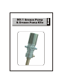
1
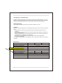
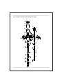
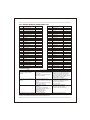
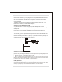
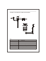
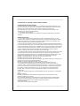
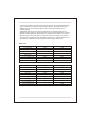
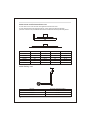
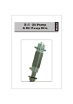
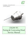
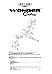
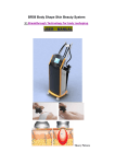
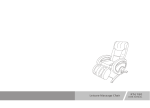
THE MANUAL OF GREASE PUMP
Read the following precautions and instructions before you begin assembly or using.
Failure to comply with these instructions could result in personal injury or property
damage. Keep these instructions in a convenient location for future reference.
IMPORTANT NOTE
The guarantee will be void if the pump has been altered in any way
PROFILE
Grease pumps are designed for transferring grease from drum to where it would be
used.
- Compressed air operated reciprocating pumps are designed for high pressure
greasing.
- Be applicable to the manipulation of all types of grease (up to NLGI-2 consistency)
from its original drums.
- The pumps can be supplied as separate components or as a complete system with
all the elements - necessary for its installation.
- The pumps can be assembled on mobile units as well as on fixed positions,
connected to steel pipes.
This manual is applicable to the following pump only, please confirm your pump is
included.
Specification
Item No.
1701501
Compression ratio
1701502
1701503
50:1
Operating pressure(bar/psi)
5-8/70-115
Maximum pressure(bar/psi)
8/115
1701500 suction
length 370/15 Gallon/min
Air tube
consumption(L/min
800/1.76
Capacity(L/min Gallon/min)
18/5
Tube diameter(mm/inch)
30/1.18
30/1.18
Suction tube length(mm/inch)
480/19
740/29
940/37
12-30/26-66
50-60/110-132
180-220/396-484
Suitable for drum(kgs/lbs)
Air inlet connection
Oil delivery connection
Noise level(dB)
1
30/1.18
1/4'' quick plug/1/4'' NPT female
Male 1/4''
82
50:1 SERIES GREASE PUMP EXPLODED VIEW
2
50:1 SERIES GREASE PUMP PART LIST
Code
Name
Quantity
Name
Code
Quantity
1
Air motor cover
1
29
Slider shell
1
2
Piston
1
30
Piston shaft
1
3
Air motor shell inside
1
31
Washer
2
4
Air motor shell outside
1
32
Spring shell
2
5
Bracket
1
33
Spring
2
6
Air control center
1
34
Spring Seat
2
7
Slider
1
35
Trip shoe guide
2
8
Gasket
1
36
Press piece
1
9
Soft gasket
1
37
Nut
1
10
Securing washer
1
102
Pin
3
11
Bracket
1
103
Ball
2
12
Washer
1
104
Circlip
1
13
Connect tube
1
105
Small circlip
2
14
Piston shell
1
106
Nut
1
15
Valve seat
1
107
Screw
2
16
Taper washer
1
208
O-ring
2
17
Filter
1
209
O-ring
2
18
Shovel washer
1
210
Silencer
2
19
Suction tube
1
211
O-ring
1
20
Shovel rod
1
212
O-ring
1
21
Valve
1
213
O-ring
1
22
Piston
1
214
O-ring
1
23
Spring
2
215
O-ring
1
24
Spring seat
1
216
O-ring
1
25
Connect shaft
1
217
O-ring
1
26
Connect shell
1
218
OD-ring
2
27
Middle shaft
1
219
Outlet
1
28
Air center cover
1
220
Quick coupling
1
221
Connector
1
Troubleshooting
Problem
The pump continues to operate
after the gun trigger has been
released
Possible Causes
Reduction of the grease delivery. 1. Air bags in the grease drum
Or reduced pressure in the grease 2. Silencer(210) dirtied
3.Blocked at some point of the grease
delivery.
circuit
4.Ball valve (103) closes incorrectly
due to dirt or wearing.
5. Damaged O-ring(216)
Air loss through the air exhaust
Solutions
1.Grease missing around the suction filter
2.There is a grease leak at some point of 1.Remove cover and take out pump and
follower plate. Compact grease and fill
the circuit
the drum or substitute it for a full one.
2.Valve(part No. 15) closes incorrectly
2.Check and tighten unions. Repair the leak.
due to dirt or wearing.
3.Disassemble and clean valves.
Substitute them if danged
1. Remove the cover and take out the
pump and the follower plate .
Compact the grease and fill the drum
2.Clean or recharge silencer
3.Use clean grease
4.Substitute damaged elements
1.The sliding valve (7) does not close 1.Disassemble and clean.
properly
Substitute them if danaged
2.The press piece(36) broken
2.Substitute damaged elements
3.Damaged O-ring(208, 209or 211)
4.Damaged piston (2)
5.Damaged washer(31)
6.Broken spring (33)
Grease leaks through the air exhaust Seal set (11) damaged
Substitute damaged elements
If the pump has anything wrong, please contact dealer or their technical supporter.
We don't recommend customer repair the pump themselves.
3
STORAGE AND MAINTENANCE
Pumps are delivered in appropriate cardboard boxes. Packaging material should be
properly disposed.
Handling and storage of the new pump do not require any special procedures.
The dust in compressed air can slow down or even block the motor cylinder. The
following steps may prevent this from happening:
1) Let in 50 gram of Vaseline oil or other lubricator from the air inlet hole weekly
operate the pump for several minutes after having lubricator into the pump.
2) Turn on the pump for several minutes until moving parts is fully lubricated.
3) You may repeat the above operation if necessary.
4) The above steps should be carried out on a weekly base.
For the pumps that are attached with compressed air treatment equipment please
empty the water retained in the reservoir of the filter-purger frequently.
For the pumps that are attached with a lubricator, please pay close attention to the
lubricator's grease level and refill with NLGL-2 conditions when necessary.
NOTE:
The user should perform only routine maintenance operations (such as filters,
silencers, cleaning...) in order not to damage it or compromise its safety. Contact our
sales or service centers when the pump needs further maintenance.
GENERAL SAFETY REGULATIONS
When the pump is connected to the compressed air supply:
- The compressed air must be filtered to avoid dust into pump
- The max compressed air pressure must not exceed 0.8Mpa
- To deliver grease, press the knob on the delivery gun; delivery stops when the knob
is released but the whole system remains under pressure.
- Position the gun so that the circuit can't open accidentally. Otherwise grease could
leak onto the ground.
- Never point the gun at people
- Press the gun knob only after you are sure that the gun is in the right place so that
the grease doesn't leak onto the ground.
- Always cut off the air supply after use so that grease can't leak out in case one of the
pump's components should break
- Use only original spare parts in case the pump has to be repaired or its components
have to be replaced
- Ensure the tightness of all joints and screwed unions.
- When no load, cut off compressed air to stop pump.
- Do not use the pump near open flames. Do not smoke during this operation.
- Wear oil-proof gloves
- The pumps can be used only to deliver grease. Do not use the pump for any other
Substance. Please contact us if you have any special request.
HOW TO USE
PUMP INSTALLATION
- When the pump is applied to a high viscosity grease, or used in low temperature, a
grease follower plate is recommended to avoid air pockets and to get the most out of
your grease. The follower plate, which is pulled towards the bottom of the drum by
suction pressure produced by the air operated pump, compress the grease,
4
preventing the formation of air pockets which may cause a blockage in delivery. And
the follower plate will always keep the grease clean to preserve its characteristics and
also enable the grease to be collected from the bottom of the drum to avoid waste.
- Loosen the bung adaptor or wall bracket adaptor star nut. Slide the bung adaptor off
of the suction tube.
- Carefully place the pump through the bung adaptor and the follower plate. Then
tighten the star nut firmly in order to attach the pump.
CONNECTION OF THE AIR INLET LINE
Air inlet connection is 1/4''quick coupling(or 1/4''NPT female) in all versions.
Compressed air connection (to be supplied by the customer) should be done using
suitable tubes.
A compressed air treatment unit (filter and regulator) is recommended to be attached
to the pump. In order to improve the efficiency of the pump, the installation of a
lubricator is also recommended.
CONNECTION OF THE REGULATOR
The lubricator (I) must be placed as close as possible to the air inlet, followed by the
pressure regulator (II) and finally, the filter (III). In the case of pumps not installed on
wall support it is very important to equip the pump's air inlet with an adaptor for quick
coupling and the air inlet hose with a quick connector.
CONNECTION OF GREASE DISCHARGE
1. The Grease discharge outlet is a 1/4''G thread.Connect the outlet to the high
pressure hose (according to DIN-SAE norms) through the corresponding adapter and
terminal.
2. Ensure the gun or corresponding valve is closed.
3. Slowly open the pump's compressed air inlet valve. The pump will start to function,
filling the feed circuit with grease. Maintain pressure on the gun until the grease starts
to come out. The pump is now ready for its usual function.
PUMP OPERATION
If the pump has already been primed and the compressed air feed is connected to the
appropriate work pressure level (5-8 bar,) the pump will start automatically when the
nozzle or gun situated at the end of the grease delivery circuit is opened.
To stop the pump, simply close the nozzle or disconnect the air inlet line.
5
CONNECT THE PUMP WITH OTHER ACCESSORIES:
Note:
Name
Code
1
Greae pump
2
Drum cover
3
Grease control valve
4
Hose with fitting
5
Air hose with quick coupling
6
7(7-1,7-2,7-3)
Drum
Filter, pressure regulator and lubricator
8
Follower plate
9
Trolley
6
THE MANUAL OF GREASE PUMP DISTRIBUTION KITS
PRESSURE RELIEF PROCEDURE
To reduce the risk of serious bodily injury, including fluid injection, splashing in the
eyes or on the skin, or injury from moving parts, please always follow this procedure
whenever you shut off the pump, when check or service any part of the
spray/dispensing system, when instal, clean or change spray tips/nozzles, and
whenever you stop spraying/dispensing.
1. Shut off the air to the pump.
2. Point the outlet of grease gun to container and trigger the grease gun to relieve
pressure.
IMPORTANT NOTES:
1. If you suspect that the spray tip/nozzle or hose is completely clogged, or that
pressure has not been fully relieved after following the steps above, VERY SLOWLY
loosen the retaining nut or hose end coupling and relieve pressure gradually, then
loosen completely. Now clear the tip/nozzle or hose.
2. On the pump downstroke, the shovel washer extends beyond the intake cylinder to
pull the material into the pump. The shovel washer works under extreme force. During
operation and whenever the pump is charged with air, the shovel washer can severely
injure or amputate a hand or finger, or break a tool, caught between it and the intake
cylinder. Always follow the Pressure Relief Procedure below, before checking,
clearing, cleaning, flushing or servicing any part of the pump.
3. This equipment conducts very high fluid pressure. Spray from the grease gun, leaks
or ruptured components can inject fluid through your skin and into your body and
cause extremely serious bodily injury, including the need for amputation. Also, fluid
injected or splashed into the eyes or on the skin can cause serious damage.
NEVER point the grease gun at anyone or at any part of the body.
NEVER put hand or fingers over the spray tip.
ALWAYS follow the Pressure Relief Procedure, right, before cleaning or removing the
spray tip or servicing any system equipment.
NEVER try to stop or deflect leaks with your hand or body.
Be sure equipment safety devices are operating properly before each use.
4. Any misuse of the system equipment or accessories, such as overpressure,
modifying parts, using incompatible chemicals and fluids, or using worn or damaged
parts, can cause them to rupture and result in fluid injection, splashing in the eyes or
on the skin, or other serious bodily injury, or fire, explosion or property damage.
NEVER alter or modify any part of this equipment; doing so could cause if any
malfunction.
CHECK all equipment regularly and immediately repair or replace worn or damaged
parts.
System Pressure
NEVER exceed the recommended working pressure or the maximum air inlet
pressure stated on your pump
Be sure that all dispensing equipment and accessories are rated to withstand the
maximum working pressure of the pump. DO NOT exceed the maximum working
pressure of any component or accessory used in the system.
Fluid Compatibility
The system is only suitable for grease.
7
5. High pressure fluid in the hoses can be very dangerous. If the hose develops a leak,
split or rupture due to any kind of wear, damage or misuse, the high pressure spray
emitted from it can cause a fluid injection injury or other serious bodily injury or
property damage.
TIGHTEN all fluid connections securely before each use. High pressure fluid can
dislodge a loose coupling or allow high pressure spray to be emitted from the coupling.
NEVER use a damaged hose. Before each use, check the entire hose for cuts, leaks,
abrasion, bulging cover, damage or movement of the hose couplings. If any of these
conditions exist, replace the hose immediately. DO NOT try to mend it with tape or any
other device. A repaired hose cannot safely contain the high pressure fluid.
Kits List
Item No.
1700512
50:1 Ratio pump
1701501
1701502
Drum application
20-30kgs/25-30lgs
50-60kgs/120kgs
Drum trolley
1708001
1708001
1709004
1700524
Drum cover
1709002
Follower plate
1709012
1709014
1/4"*13' connection hose
1762213
1762213
Grease gun
1785701
1785701
Z-swivel
1785702
1785702
1700536R
Item No.
1700536
50:1 Ratio pump
1701503
1701503
Drum application
180-220kgs/400lbs
180-220kgs/400lbs
Drum trolley
1708002
1708003
Drum cover
1709006
1709006
Follower plate
1709016
1709016
1/4"*13' connection hose
1762213
***
Grease gun
1785701
1785701
Z-swivel
1785702
1785702
1/4"*50' grease hose reel
***
H820152
1/4"*5' connection hose
***
1762205
Drum Cover and Follower Plate List
Put the drum cover onto the drum and tighten the three locks crew.
Put the follower plate into the grease drum, on the grease surface horizontally,
pressure it as much as possible to exhaust the air between follower plate and grease.
Drum cover
Diameter(mm)
Flower plate
Diameter(mm)
For drum with
capacity of(kgs)
1709001
280
1709011
265
12-20
1709002
310
1709012
310
16-30
1709003
350
1709013
340
20-30
1709004
385
1709014
370
50-60
1709005
420
1709015
410
50-60
1709006
600
1709016
585
180-200
Drum Trolley List
9
Item No.
For drum with capacity(kgs)
1708001
12-60
1708002
180-220
1708003
180-220