1
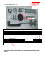
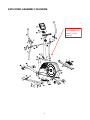
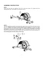
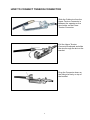
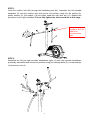
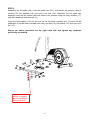
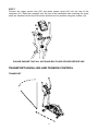
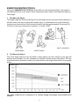
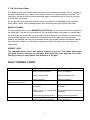
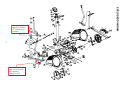
ER5000D
Escalade International Limited
Pleasant Road, Penllergaer, Swansea. SA4 9GE
Tel: 00 44 1792 222 550 Fax 00 44 1792 895 781
www.escaladesports.co.uk
[email protected]
CONTENTS
Important Information
3
Hardware Parts List
4
Pre Assembly Check List
5
Exploded Assembly Diagram
6
Assembly Instructions
7
Transport/Levelling and Tension Control
11
Computer Instructions
13
Exercise Instructions
15
Fault Finding Chart
16
Exploded Diagram
17
Parts List
18
Additional Information
Care Maintenance
Limited Warranty
19
20
Supplied by
Escalade International Ltd
Pleasant Road
Penllergaer
Swansea
SA4 9GE
Tel: 00 44 1792 222550
Fax: 00 44 1792 895781
www.escaladesports.co.uk
2
IMPORTANT SAFETY INFORMATION
READ ALL INSTRUCTIONS BEFORE USING
THIS OWNER’S MANUAL CONTAINS ASSEMBLY, OPERATION, MAINTENANCE
AND SAFETY INFORMATION. IN THE INTEREST OF SAFETY, PLEASE MAKE
CERTAIN THAT YOU READ AND UNDERSTAND ALL THE INFORMATION
BELOW.
1. This elliptical is intended for class H (H=Domestic) use only. It is not designed for
commercial use.
2. This machine has been tested to BS EN 957 Parts 1:2005 and Part 9:2003.
3. Read the OWNER’S OPERATION MANUAL and all accompanying literature and follow
it carefully before using your elliptical.
4. Keep children and pets away from the Elliptical at all times. Do not leave children
unattended in the same room with the Elliptical. The Elliptical is not a toy and therefore
parents and guardians should be aware of the natural tendency for children to play,
leading to situations and behaviour for which the Elliptical is not intended.
5. If children are allowed to use the Elliptical their physical/mental development and above
all, temperament should be taken into account. Constant supervision is therefore
needed.
6. Position the Elliptical on a clear levelled surface which is clear of all obstacles as not to
restrict movement whilst exercising. DO NOT use the Elliptical near water or outdoors.
7. Exercise equipment has moving parts. In the interest of safety, keep others, especially
children, at a safe distance while exercising.
8. Never hold your breath while exercising. Breathing should remain at a normal rate in
conjunction with the level of exercise being performed.
9. Rest adequately between workouts. Muscle tone develops during these rest periods.
Beginners should work out twice a week and increase gradually to 4 to 5 times per week.
10. Remove all jewellery, including rings, chains and pins before commencing exercise.
11. Always wear suitable clothing and footwear during exercise. Do not wear loose fitting
clothing that could become entangled with the moving parts of your exercise machine.
IMPORTANT!!! THE MAXIMUM RECOMMENDED WEIGHT CAPACITY FOR YOUR
ELLIPTICAL IS 120KGS.
3
Revised picture
needs to be added
to show 4 x #10 as
previously
discussed in
inspection report.
HARDWARE PARTS LIST
Should be #11
Part No.
Description
Q’ty
3
4
8
9
10
Curved washer
Carriage nut M8
Flat washer 30mm diameter
Plastic washer
Flat washer 19mm diameter
4
4
2
2
2
17
39
49
Wavy washer
Carriage bolt M8*73L
Screw M8*16
Allen key S6
Allen key S5
Allen Wrench 10/13/19
2
4
4
2
1
1
Should be quantity
x4
Should be #11
Please note that some items of hardware may already be pre assembled onto your
elliptical.
4
PRE-ASSEMBLY
PRE-ASSEMBLY CHECK
CHECK LIST
LIST
No.27
No.27
No.41
No.41
No.34L
No.34L
No.40
No.40
Should be #21
No.31
No.31
No.6
No.6
No.29
No.29
No.44
No.44
PART No.
No.
PART
No.34R
No.34R
DESCRIPTION
DESCRIPTION
No.2
No.2
No.38
No.38
Q’TY
Q'TY
No.31
No.31
MAIN
MAINFRAME
FRAME
1
No.44
No.44
FRONT
FRONTPOST
POST
11
No.27
No.27
PEDAL
PEDALARMARM
22
No.41
No.41
COMPUTER
COMPUTER
11
No.6
No.6
LOWHANDLEBAR
HANDLEBAR
LOW
Should
be STABILIZER
#21
REAR
22
No.29
No.29
REAR STABILIZER
1
No.34
No.34
PEDAL
FEDALR/L
R/L
22
No.40
No.40
AXIS
AXLE FOR
FORHANDLEBAR
HANKLEBAR
1
No.2
No.2
LEFT
& RIGHT UPPER HANDLEBAR
UP
HANDLEBAR
22
No.38
No.38
FRONT
FRONTSTABILIZER
STABILIZER
11
Above described parts are all the parts you need to assemble this machine. Before
you start to assemble, please check the hardware packing to make sure they are
included.
5
EXPLODED ASSEMBLY DIAGRAM
Please confirm if
part numbers are
correct on this
diagram.
6
ASSEMBLY INSTRUCTION
STEP 1
Attach the front and rear stabilizer (38 & 29) to the main frame (31), tighten with four
carriage bolts (39), curve washer (3) and acorn nut (4).
STEP 2
Take the handlebar post (44) and connect the upper sensor wire (32) to the lower sensor
wire (51). Ensure the Tension Control Knob is set to number 8. Connect the upper
tension cable (62) to the lower tension cable (50). Please see the next page for a detailed
description of this part of the assembly. Insert the handlebar post (44) into the main
frame (31) and secure into position using 4 allen head bolts (49) and curved washers (3).
Do not fully tighten the allen bolts at this stage.
44
7
HOW TO CONNECT TENSION CONNECTOR
Slide the Cable wire from the
Upper Tension Connector in
between the opening on the
wire holder on the Lower
Tension Connector.
Pull the Upper Tension
Connector backward and slide
the wire through the slot on the
bracket.
Drop the Connector down so
the fitting sits firmly on top of
the bracket.
8
STEP 3
Insert the rotation axle (40) through the handlebar post (44). Assemble the left movable
handlebar (6) onto the rotation axle and secure into position using one flat washer (8),
plastic washer (9), flat washer (10) and allen head bolt with blue dot (11). Repeat this
procedure for the right handlebar. Do not fully tighten the allen head bolts at this stage.
If diagram correct
on page 6, #17 will
need to be
included at this
point
STEP 4
Assemble the left and right movable handlebars upper (2) onto the movable handlebars
previously assembled and secure into position using four carriage bolts (5), curved washers
(4) and acorn nuts (4).
9
STEP 6
Assemble the left pedal (34L) onto the pedal arm (21L) and secure into position using 2
screws (35), flat washers (18) and nylon lock nuts (19). Assemble the left pedal arm
assembly onto the left rotation disk and secure into position using one wavy washer (17),
and allen head bolt with blue dot (11).
Insert the steel spacer (14) into the end on the left lower movable arm. Connect the left
pedal arm to the left lower movable arm using one bolt (16), flat washer (10) and nylon lock
nut (12).
Repeat the above procedure for the right hand side and tighten any hardware
previously assembled.
If diagram is
correct on page 6
this will need to be
changed to #10
10
STEP 7
Connect the upper sensor wire (32) and pulse sensor wires (42) into the rear of the
computer (41). Slide the computer onto the top of the handlebar stem ensuring the loose
wires are inserted into the top of the stem and secure into position using two screws (43).
PLEASE ENSURE THAT ALL NUTS AND BOLTS ARE SECURE BEFORE USE
TRANSPORT/LEVELLING AND TENSION CONTROL
TRANSPORT
11
LEVELLING
TENSION CONTROL
Decrease
Increase
12
COMPUTER INSTRUCTIONS
UT8365-7
BUTTON:
MODE:
To select functions of time, speed, distance, calories and pulse.
To adjust each function value of time, distance, calorie, pulse.
The user may use reset key to reset each function individually: time, distance,
RESET:
calorie, and pulse.
The user may use the recovery button to determine their fitness level after
RECOVERY:
exercising.
SET:
FUNCTION
1. Scan: Automatically scans through each function in sequence so that you can see you
progress without pressing the “mode” button each time. Display switches every 6 seconds.
2. Time: Automatically accumulate workout time when starting exercise. 0:00~99:59 minutes.
3. Speed: Display current speed during workout time. 0.0~99.9 KM/HR.
4. Distance: Automatically accumulate workout distance when starting exercise. 0.00~99.99 K/M
5. Calories: Automatically accumulate calories amount consumed when starting exercise.
0~9999
6. Pulse: Displays your current heart rate when exercising. P~30~240
NOTE:
1.
2.
3.
The value of pulse function is for reference only; please do not consider for medical
purposes.
The monitor will be automatically shut off after 4 to 5 minutes when not in use.
The monitor will be auto-powered on when you start exercising, or push a button.
13
Getting Started
The computer will automatically sense when you begin to exercise. The functions of Speed,
RPM, Time, Distance and Calories will begin to count up as soon as you begin exercising
and stop when you have finished.
Entering Preset Data
1.
Press MODE until the function you wish to enter is flashing.
2.
Press SET to input your preset data. You can press RESET at any time to reset the
function data to zero.
3.
Once your preset data has been entered, you may begin exercising. Preset data will
begin to count down automatically. An alarm will sound once the preset data
reaches ZERO.
Recovery Feature
This computer is equipped with a Recovery Feature. This special feature can help you to
understand your heart rate recovery status after each workout.
Press the Recovery button after your entire workout program. Place both hands on the
pulse sensor; the time will display one minute (00:60) and count down. The computer will
monitor your heart rate during this one-minute and display your heart rate recovery status
after the minute.
Score
Condition
Heart Rate Per Minute
F1
Excellent
75 - 80
F2
Good
85 - 90
F3
Average
95 - 115
F4
Fair
120 - 125
F5
Poor
130 - 135
F6
Very Poor
135+
Hand Pulse Sensors
Your elliptical comes with hand pulse sensors that can be found on the handlebars. To
operate, place your palms on the sensors. It will take a few seconds for your heart rate to be
displayed, which is initially indicated by a flashing heart on the computer.
14
EXERCISE INSTRUCTION S
Using your MAGNETIC ELLIPTICAL will provide you with several benefits, it will improve
your physical fitness, tone muscle and in conjunction with a calorie controlled diet help you
lose weight.
1. The Warm Up Phase
This stage helps get the blood flowing around the body and the muscles working properly. It
will also reduce the risk of cramp and muscle injury. It is advisable to do a few stretching
exercises as shown below. Each stretch should be held for approximately 30 seconds, do
not force or jerk your muscles into a stretch - if it hurts, STOP.
INNER THIGH
FORWARD
BENDS
CALF / ACHILLES
SIDE BENDS
OUTER THIGH
2. The Exercise Phase
This is the stage where you put the effort in. After regular use, the muscles in your legs will
become more flexible. It is very important to maintain a steady tempo throughout. The rate
of work should be sufficient to raise your heart beat into the target zone shown on the graph
below.
This stage should last for a minimum of 12 minutes though most people start at about 15-20
minutes.
15
3. The Cool Down Phase
This stage is to let your Cardio-vascular System and muscles wind down. This is a repeat of
the warm up exercise e.g. reduce your tempo, continue for approximately 5 minutes. The
stretching exercises should now be repeated, again remembering not to force or jerk your
muscles into the stretch.
As you get fitter you may need to train longer and harder. It is advisable to train at least
three times a week, and if possible space your workouts evenly throughout the week.
MUSCLE TONING
To tone muscle while on your MAGNETIC ELLIPTICAL you will need to have the resistance
set quite high. This will put more strain on our leg muscles and may mean you cannot train
for as long as you would like. If you are also trying to improve your fitness you need to alter
your training program. You should train as normal during the warm up and cool down
phases, but towards the end of the exercise phase you should increase resistance making
your legs work harder. You will have to reduce your speed to keep your heart rate in the
target zone.
WEIGHT LOSS
The important factor here is the amount of effort you put in. The harder and longer
you work the more calories you will burn. Effectively this is the same as if you were
training to improve your fitness, the difference is the goal.
FAULT FINDING CHART
FAULT
Computer does not work.
REASON
Upper and lower computer
wires are not connected.
REMEDY
Connect upper and lower sensor
wires. See Steps 2.
Faulty computer wire.
Replace computer wire.
Faulty computer.
Computer display becomes Weak or faulty batteries
faint or does not count.
Pulse does not register.
Pulse
sensor
wire
connected.
Replace computer.
Replace batteries
not Check connection.
See step 7.
Hands not in full contact with Remove hands from sensors and
reposition.
pulse sensors.
No resistance while exercising.
Replace hand grip sensors.
Faulty hand grip pulse sensor.
Upper and lower tension Connect upper and lower tension
control cables not connected
cables See Step 2
16
17
If comment on
page 10 is correct
this needs to
change to #10
EXPLODED DIAGRAM
If comment on
page 9 is correct,
#17 needs to be
included
PARTS LIST
NO
1
2
3
4
5
6
7
8
9
10
11
12
13
14
15
16
17
18
19
20
21
22
23
24
25
26
27
28
29
30
31
32
33
34
35
36
37
38
39
40
Description
END CAP
LEFT & RIGHT UPPER HANDLEBAR
CURVED WASHER
ACORN NUT
CARRIAGE BOLT
LOW HANDLEBAR
BIG PLASTIC BUSH
FLAT WASHER 30mm diameter
PLASTIC WASHER
FLAT WASHER 19mm diameter
M8 ALLAN HEAD BOLT WITH BLUE DOT
NYLON LOCK NUT
POWER METALLURGY BUSH
STEEL SPACER
TUBE END CAP
M8*55mm BOLT
WAVY WASHER
FLAT WASHER
M6 NYLON LOCK NUT
NYLON BUSH
PEDAL ARM (LEFT & RIGHT)
SCREW FOR COVER
HEXAGON M8 SCREW
TURNDISK
DISC END CAP
SCREW FOR CROSS BRACE
CROSS BRACKET
REAR LEVELLER(L/R)
REAR STABILIZER
SCREW FOR COVER
MAIN FRAME
UPPER SENSOR WIRE
MAGNET SET
PEDAL (LEFT & RIGHT)
M6 SCREW
FRONT LEVELLER(L/R)
SCREW
FRONT STABILIZER
M8*75mmL CARRIAGE BOLT
ROTATION AXLE
Q’ty
NO
2
2
12
8
4
2
6
2
2
2
2
3
4
2
2
2
2
4
4
4
2
6
2
2
2
8
2
2
1
4
1
1
1
1
4
2
2
1
4
1
41
42
43
44
45
46
47
48
49
50
51
52
53
54
55
56
57
58
59
60
61
62
63
64
65
66
67
68
69
70
71
72
73
74
75
76
77
78
79
80
18
Description
COMPUTER
PULSE SENSOR WIRE
SCREW FOR COMPUTER
HANDLEBAR POST
END CAP
HAND SENSOR
SMALL DECORATION COVER
TENSION CONTROLER
M8 ALLAN HEAD BOLT
LOWER TENSION CABLE
BELOW SENSOR WIRE
SCREW FOR FLYWHEEL
BUSH
6000ZZ BEARING
FLYWHEEL
SCREW
ZIP SET FOR FLYWHEEL
AXIS FOR FLYWHEEL
BUSH FOR IDLE WHEEL
IDLE WHEEL
6900ZZ BEARING
UPPER TENSION CABLE
M8 HEXAGON SCREW
AXIS FOR BIG PULLEY
BIG PULLEY
6203ZZ BEARING
M8 BOLT
C-SHAPE WASHER
SPRING WASHER
CHAIN COVER(L/R)
Q’ty
1
2
2
1
2
2
1
1
4
1
1
3
2
2
1
2
2
1
1
1
2
1
3
1
1
2
1
1
1
2
ADDITIONAL INFORMATION
Packaging Disposal
Government guidelines ask that we reduce the amount of waste material disposed of in land
fill sites. We therefore ask that you dispose of all packaging waste responsibly at public
recycling centres.
End of Life Disposal
We at Escalade hope you enjoy many years of enjoyable use from your Elliptical. However,
a time will come when your Elliptical will come to the end of its useful life. Under ‘European
WEEE Legislation’ you are responsible for the appropriate disposal of your Elliptical to a
recognised public collection facility.
CARE AND MAINTENANCE
1.
2.
3.
4.
5.
Inspect and tighten all parts before using the elliptical.
The elliptical can be cleaned using a damp cloth and mild non-abrasive detergent.
DO NOT use solvents.
Examine the elliptical regularly for signs of damage or wear.
Failure to examine the elliptical regularly may affect the safety level of the
equipment.
Replace any defective components immediately and/or keep the elliptical out of use
until repair.
SPECIFICATIONS
Dimensions:
114 x 59 x 153 cms
Maximum user weight: 120kg
Batteries
2 x Size AA 1.5v
19
LIMITED WARRANTY
Escalade warrants this product to be free from defects in workmanship and material, under
normal use and service conditions, for a period of one year from the date of purchase. This
warranty extends only to the original purchaser. Escalade’s obligation under this Warranty is
limited to replacing damaged or faulty parts at Escalade’s option.
All returns must be pre-authorised by Escalade. This warranty does not extend to any product
or damage to a product caused by or attributable to freight damage, abuse, misuse, improper
or abnormal usage, purchasers own repairs or for products used for commercial or rental
purposes. No other warranty beyond that specifically set forth above is authorized by
Escalade.
Escalade is not responsible or liable for indirect, special or consequential damages arising out
of or in connection with the use or performance of the product or other damages with respect to
any economic loss, loss of property, loss of revenues or profits, loss of enjoyments or use,
costs of removal, installation or other consequential damages or whatsoever natures.
The warranty extended hereunder is in lieu of any and all other warranties and any implied
warranties of merchantability or fitness for a particular purpose is limited in its scope and
duration to the terms set forth herein.
Your statutory rights are not affected.
ORDERING REPLACEMENT PARTS
Replacement parts can be ordered by calling our Customer Service Department 9.00 am to
5.00 pm
Tel:
E mail:
0044 (0) 1792 222 562
[email protected]
When ordering replacement parts please give the following information.
1.
2.
3.
4.
Model
Description of Parts
Part Number
Date of Purchase
20