1
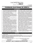
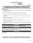
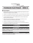
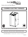
INSTALLATION AND USER MANUAL
IN CANA
AD
I
Q
UÉ
N
R
FB0002
A
FA B
®
DE
DA
MA
D SERIES ELECTRIC FURNACE
A
AU C
MODELS: 21D10, 21D15, 21D18, 21D20, 21D23, 21D25 AND 21D27
IMPORTANT: READ AND SAVE THESE INSTRUCTIONS.
Broan-NuTone Canada Inc.; Mississauga, Ontario www.broan.ca 877-896-1119
30042479C
! WARNING
• Never tamper with the unit or its controls. User MUST contact a
specialized contractor when a failure occurs. DO NOT ATTEMPT
to repair.
• When using a humidifier make sure not to damage the heating
element bank.
• We recommend that your unit be inspected by a specialized
technician once a year.
• Poor maintenance of air filters OR an unbalanced static pressure
may result in a performance decrease.
• Always use genuine parts for maintenance or service call. The
use of unbranded parts will void the warranty.
• The use of this unit without an air distribution duct will void the
warranty.
• It is strictly forbidden to use jumpers to simulate heat demand.
• Risk of electrical shock. Disconnect power before installation,
servicing, maintenance or field wiring. Replace all panels before
operating. Failure to do so can result in electrical shock causing
severe injuries or death.
• When performing installation, servicing or cleaning the unit, it is
recommended to wear safety glasses and gloves.
• To assure a proper performance of your furnace, we recommend
that you use high quality name brand thermostats.
• When applicable local regulation comprises more restrictive
installation and/or certification requirements, the aforementioned
requirements prevail on those of this document and the installer
agrees to conform to these at his own expenses.
• For your safety, do not store or use gasoline or other flammable
liquids and vapors in the vicinity of this unit or any other
appliance.
• These instructions are intended to be used by qualified personnel
who have been trained in installing this type of furnace. Installation
of this furnace by an unqualified person may lead to equipment
damage and/or hazardous condition which may lead to bodily
harm.
• This furnace is not watertight and is not designed for outdoor
installation. This furnace shall be installed in such a manner as to
protect its electrical components from water. Outdoor installation
leads to a hazardous electrical condition and to premature
furnace failure, thus voiding the warranty.
• Do not block the combustion air openings in the furnace. Any
blockage will result in improper overheat situation and may result
in a fire hazard and/or cause bodily harm.
• The unit must have an uninterrupted or unbroken electrical
ground to minimize personal injury if an electrical fault should
occur. When performing electrical connection, the ground
conductor must be firmly attached to the ground lug in the furnace.
• Do not use this furnace as a construction heater. Use of this
furnace as a construction heater exposes the furnace to abnormal
conditions, contaminated combustion air and the lack of air filters.
Failure to follow this warning can lead to premature furnace failure
and/or vent failure which could result in a fire hazard and/or
bodily harm.
• The owner and/or the user is responsible of the following:
Always maintain the immediate surrounding of the furnace free
from combustible and highly flammables materials.The furnace
ambient air should not have an excessive dust concentration
and humidity. Never operate this central heating appliance without
an air filter.
• Before performing any service functions, unless operations
specifically require the power to be on, make sure all utilities are
turned “OFF” upstream of the appliance. Failure to comply with
this warning will cause a fire hazard and/or bodily harm.
• All questions regarding the operation, maintenance or warranty
of this unit should be addressed to the company where this
product has been sold from.
CAUTION
• Never burn garbage or paper in the heating system and never leave rags or paper around the unit.
• Return air grilles and warm air registers must not be obstructed.
IMPORTANT: All local and national code requirements governing the electrical installation heating equipment, wiring and flue connections
must be followed. Some of the codes that may be applicable are :
ANSI/NFPA 70 NATIONAL ELECTRICAL CODE
CSA C22.1 CANADIAN ELECTRICAL CODE
Only the latest issues of the above codes should be used, and are available from either:
The National Fire Protection Agency
or
Batterymarch Park
Quincy, MA 02269
-2-
The Canadian Standards Association
178 Rexdale Blvd.
Rexdale, Ontario M9W 1R3
TABLE OF CONTENTS
1. DIMENSIONS .............................................................................................................................................. 3
2. GENERAL REQUIREMENTS AND SPECIFICATIONS ............................................................................... 4
3. OPERATING OPTIONS ............................................................................................................................... 5
4. BREAKERS ................................................................................................................................................. 5
5. INSTALLATION NOTES ............................................................................................................................... 6
5.1 COLD AIR RETURN ....................................................................................................................................................... 6
5.2 ELECTRICAL WIRING - POWER SUPPLY ............................................................................................................................ 6
5.3 CONNECTING AND ADJUSTING THE LOW VOLTAGE THERMOSTAT ............................................................................................ 6
6. USE IN MOBILE HOMES ............................................................................................................................ 6
7. USING OPTIONAL EQUIPMENT ................................................................................................................. 7
7.1
7.2
7.3
7.4
TWO-STAGE OR OUTDOOR THERMOSTAT .......................................................................................................................... 7
AIR CONDITIONING ....................................................................................................................................................... 7
ELECTRONIC AIR CLEANERS AND/OR POWERED FURNACE HUMIDIFIERS ................................................................................. 7
INTERLOCK CONNECTION ............................................................................................................................................... 7
8. WIRING DIAGRAMS ................................................................................................................................8-11
9. SERVICE PARTS ........................................................................................................................................12
10. MAINTENANCE ..........................................................................................................................................13
11. TROUBLESHOOTING ................................................................................................................................13
12. WARRANTY ................................................................................................................................................14
1. DIMENSIONS
TOP VIEW
1½”
(38 mm)
WIRING KO’S VALUES
17” x 17”
A = 1³/8” (35 mm)
B = 1¼” (32 mm) & 1¾” (44 mm)
C = 7/8” (22 mm) & 2” (51 mm)
(432 mm x 432 mm)
1½”
20”
(508 mm) DISCHARGE (38 mm)
FRONT VIEW
20”
(508 mm)
39”
(991 mm)
RIGHT SIDE VIEW
REAR VIEW
LEFT SIDE VIEW
1”
(25 mm)
FILTER FRAME
(EITHER SIDE, REAR
OR BOTTOM)
1½” x 1½” KO
(38 mm x 38 mm)
WIRING KO’S
A
B
C
WIRING KO’S
C
18” x 18”
18” x 18”
18” x 18”
(457 mm x 457 mm)
(457 mm x 457 mm)
(457 mm x 457 mm)
RETURN
1½” x 1½” KO
(38 mm x 38 mm)
FK0004A
-3-
RETURN
1½” x 1½” KO
(38 mm x 38 mm)
RETURN
2. GENERAL REQUIREMENTS AND SPECIFICATIONS
CAUTION
This unit must be installed in a dry place, in a non-corrosive, well-ventilated environment, without excessive dust. The
ambient temperatue must be over 10°C and under 27°C. If the ambient temperatue is 10°C or less, the plenum must be
insulated on 10 ft linear minimum length.
1. LOCATION - The furnace should be centrally located to the heating area.
2. POSITIONS - It can be installed for vertical, horizontal or downflow operation. When installed horizontally, the furnace should be positioned such as the
door will not end up being on the top. The door should be on the side of the furnace, to ensure that the motor bearings are in their designed position. In
vertical downflow installations, use only “L”- or “T”-shaped plenum with no openings or registers directly below furnace.
3. INSTALLATION CLEARANCES - As shipped from the factory, each unit is approved for “zero inch” clearance. If additional clearance is required, it will be
indicated on the data label attached to the furnace.
4. TEMPERATURE RISE - Furnaces are shipped to operate at 0.20” W.C. (50 Pa) external static pressure. They are certified for operation up to
0.50” W.C. (125 Pa). Check below for temperature rise table on specification chart and, if necessary, adjust the unit to match.
5. SERVICE CLEARANCE - Units are serviced from the FRONT. Leave at least 24” (610 mm) clearance in front of the door.
240 VOLTS - SINGLE PHASE
TEMPERATURE RISE @ 0.20” W. C.
MODEL NO.
KW
BTHU
AMPS INCL. MOTOR
HP
21D10
10
34152
46
21D15
15
51228
21D18
18
61473
BLOWER
1/3
°C
23
°F
41
*SPEED
LOW
RPM
663
67
1/3
24
43
MED-LOW
814
77
1/3
10” x 8”
27
49
MED-LOW
814
(254 mm x 203 mm)
21D20
20
68304
86
1/3
33
59
MED-LOW
814
21D23
22.5
76842
94
1/3
36
65
MED-LOW
814
21D25
25
85379
107
1/3
37
67
MED-LOW
814
21D27
27
92210
116
3/4
36
65
MED-HIGH
707
12” x 8”
(304 mm x 203 mm
*FACTORY SETTINGS.
SUBJECT TO CHANGE WITHOUT NOTICE
10” x 8” (254 mm x 203 mm) BLOWER
12” x 8” (304 mm x 203 mm) BLOWER
STATIC PRESSURE
(INCHES OF WATER COLUMN)
0.2
0.3
0.4
0.5
0.6
SPEED
FLOW
RATE
CFM
L/s
756
357
749
353
740
349
729
344
713
337
LOW**
CFM
L/s
727
343
699
330
667
315
636
300
606
286
MED-LOW
CFM
L/s
1035
488
1018
480
997
470
971
458
935
441
MED-LOW**
CFM
L/s
912
431
897
423
878
414
853
402
823
388
MED-HIGH
CFM
L/s
1177
556
1157
546
1132
534
1102
520
1063
502
MED-HIGH
CFM
L/s
1216
574
1200
566
1181
557
1157
546
1129
533
HIGH
CFM
L/s
1301
614
1276
602
1247
588
1207
569
1145
540
HIGH
CFM
L/s
1640
774
1601
755
1558
735
1513
714
1466
692
SPEED
FLOW
RATE
LOW
WARNING:
** These speeds can only be run with heater off, for cooling/ventilation purposes only.
-4-
STATIC PRESSURE
(INCHES OF WATER COLUMN)
0.2
0.3
0.4
0.5
0.6
3. OPERATING OPTIONS
The furnace is shipped from the factory in a “Standard Heating Mode” (all switches are in the Down position). When the thermostat calls for heat, the automatic
controls will be activated and the furnace turned “ON”.
The blower will run at low speed or higher speed (as selected by SPEED SELECTOR switch).
As the furnace heats up, it automatically switches to the pre-programmed heating speed when additional elements are activated by the electronic control, if
it was initially set to run at low speed. The timing of this blower speed change will depend on whether FAST or SLOW is selected on the HEAT ACTIVATION switch.
You may, however, change from the Standard Heating Mode by using the controls built into your furnace.
SPEED SELECTOR
HEAT ACTIVATION
HIGH
SLOW
LOW
FAST
The SPEED SELECTOR switch is used to control the fan speed (ventilation).
Even if there is no call for heat, the ventilation can be controlled by the
thermostat; the fan speed is determined by this switch.
During spring or fall, you may require less rapid response when the
thermostat calls for heat.
LOW – The blower motor will operate at low speed.
When FAST is selected, the heating elements come online faster.
When SLOW is selected, it takes more time to bring all the elements online.
HIGH – The blower motor will operate at a higher speed.
Slow (First Stage)
Slow Response Sequence
Fast (Second Stage)
Rapid Response Sequence
Element 1 - Heat on instantly
Element 1 - Heat on instantly
Blower on after a 3-second delay
Blower on after a 3-second delay
Elements 3 and 5
after a 1-minute delay
Elements 3 and 5
after a 10-second delay
Element 2 after a 2-minute delay
Element 2 after a 20-second delay
Element 4 and 6
after a 3-minute delay
Element 4 and 6
after a 30-second delay
NOTE: Elements 4, 5 and 6 only where applicable.
4. BREAKERS
D Series furnaces are equipped with breakers, located on the front panel
of the unit. These devices protect the heating elements from overcurrent.
If this situation occurs, the breakers will open to cut the power from the
heating elements only.
NOTE: The number of breakers varies according to the furnace
model; 21D10 model has no breakers, 21D15, 21D18 and
21D20 models have 2 breakers and 21D23, 21D25 and 21D27
models have 3 breakers. Refer to Section 8 Wiring Diagrams.
BREAKERS
FD0001
! WARNING
Breakers do not cut power to entire furnace, only to the heating elements. Do not use the breakers to turn off the furnace.
The power to the whole unit can only be cut from the main electrical panel.
-5-
5. INSTALLATION NOTES
5.1 COLD AIR RETURN
The duct can be attached to either side, rear or the bottom of the furnace.
For side return there are four 1½” (38 mm) knockouts which can be removed and used as an outline for cutting a 18” x 18” (457 mm x 457 mm)
return air opening in the furnace left or right side. Mount the filter frame to the furnace over the opening with the open side of the frame facing front.
Then attach the 19” x 19” (483 mm x 483 mm) air duct to the flanges on the filter frame.
For bottom mounting, remove the screws holding the bottom plate to the furnace, discard the bottom plate and attach the filter frame to the bottom
flanges with the open side of the frame facing front.
5.2 ELECTRICAL WIRING - POWER SUPPLY
The furnaces are completely factory wired. From a separate breaker, a two-wire plus ground supply wire is required. The ground conductor must be
firmly attached to the ground lug in the furnace and the supply wires to the terminal block in the furnace.
NOTE: When a FK120 kit is used to supply an air cleaner and/or humidifier, a third (neutral) conductor must be brought into the furnace.
! WARNING
For all installations, we only recommend appropriate gauge good quality copper wire(s). However, it is the electrician’s
responsibility to ensure that the wiring and connections are compliant to the latest editions of the Canadian Electrical Code
and local codes.
5.3 CONNECTING AND ADJUSTING THE LOW VOLTAGE THERMOSTAT (Use only class 1 wires inside furnace compartments.)
Attach thermostat wires to the low voltage terminal block located on the inside of the furnace. Follow the diagrams supplied with the thermostat. As a
general guide, remember that the R & W terminals control single stage heating; the R & Y terminals control cooling. Single stage cooling uses “Y/Y2”
as first and only stage.Two-stage cooling uses “Y1” as first stage and “Y/Y2” as second stage. Make sure the thermostat is levelled on the wall and in
appropriate location as per instructions supplied with the thermostat.
CAUTION
Before turning the furnace on, the heat anticipator in the thermostat must be properly set.
Because each installation is different an accurate reading of the current draw should be made with an AC meter. Set the meter at 2 A range for
furnaces through 20 kW, and at 4 A range for larger units.
A. Set the anticipator at its highest setting.
B. Disconnect the “W1” thermostat wire from the furnace low voltage terminal connections.
C. Connect the AC meter between the “W1” terminal on the board and the loose “W1” wire.
D. Turn the thermostat up to start the furnace and allow it to run,with all elements on, for three or four minutes.
E. Read the current draw on the meter and reset the anticipator to match the meter reading.
6. USE IN MOBILE HOMES
Models 21D10, 21D15, 21D18 and 21D20 are certified for “L”-shape
and “T”-shape shallow duct installation with model FSB-1 sub-base in
downflow applications when the supply air ducts pass through the floor
of the structure. Recommended size of a floor opening: 14¼” x 14¼”
(362 mm x 362 mm). The duct system must be designed so that the external
static pressure of the system does not exceed the maximum external static
pressure of 0.50” W.C. (125 Pa).
SHALLOW DUCT AREA REQUIREMENTS
-6-
DUCT DEPTH
DUCT WIDTH
4” (102 mm)
16” (406 mm)
5” (127 mm)
13” (330 mm)
6” (152 mm)
10” (254 mm)
7. USING OPTIONAL EQUIPMENT
7.1 TWO-STAGE OR OUTDOOR THERMOSTAT
(The HEAT ACTIVATION switch must be in the SLOW position).
Follow the directions supplied with the two-stage or outdoor thermostat in conjunction with the furnace wiring diagram.
7.2 AIR CONDITIONING
THERMOSTAT
Your furnace is equipped with all the controls required for the addition
of air conditioning (except the heat-cool thermostat).
The evaporator coil may be installed by a local contractor in sheet
metal plenum of his own manufacture. The coil should be located:
centred over the “chimney” of the furnace 4” (102 mm) to 6” (152 mm)
above the top of the furnace.
Make sure no air is allowed to bypass the cooling coil during cooling
operation. If the discharge opening is a great deal larger than the
coil, and the ductwork is correspondingly larger than the coil, you
may want to use a bypass damper for heating. The damper would be
closed in summer, directing all air flow through the coil. In winter the
damper would be open to allow air to bypass the coil.
Typical air-conditioning field wiring connections are shown in the
diagram at right.
CONDENSER
FURNACE
FE0001A
WIRING COLOR CODE
C
G
COMMON
GREEN
R
RED
W1
W2
Y
WHITE
WHITE (BLUE
OPTIONAL)
YELLOW
7.3 ELECTRONIC AIR CLEANERS AND/OR POWERED FURNACE HUMIDIFIERS
These units operate at 120 V. Your 240 V furnace is designed so that Model FK120 adaptor kit can be mounted inside the furnace to supply the
required 120 V. Instructions for mounting and wiring are included with the kit.
7.4 INTERLOCK CONNECTION
When the electric furnace is used in combination with another device
(as for example, a wood burning furnace), it is recommended to perform
the connection by referring to the wiring diagram at right. The burning
furnace thermostat will then turn automatically on the blower in the
electric furnace.
External Request
for Fan Activation
G
Relay
Electric Furnace
System
Furnace
Thermostat
R
Furnace
NC
COM
FE0034A
-7-
NO
R
24 VAC
Power Output
G
Call for FAN
8. WIRING DIAGRAMS
! WARNING
Risk of electric shock. Disconnect power before installation, servicing, maintenance or field wiring. Replace all panels
before operating. Failure to do so can result in electric shock causing severe injuries or death.
21D10 Model
Open: 93.3°C
MRTP 1
W
MRTP 2
W
W
W
P
P3
24V
DC
GR
PP
GR
B
P2-8
P2-6
PP
P2-5
B
NC
1
24V
DC
GR
LO
P2-2
10 KW 240 VAC
Single phase
R
Y
BL
P2-1
L1
HI
MED-HI
C
BL (MED-HI)
M
2. Field wiring must comply with applicable
codes, ordinances and regulations. Use only
Class 1 wiring inside furnace compartments.
CALL FOR FAN
CALL FOR COOL
REVERSING VALVE
CALL FOR HEAT 1
CALL FOR COOL 1
L1
B
B
R
BR
R (LO)
Y
Y
R
B
21D15 Model
Open: 93.3°C
MRTP 1
MRTP 2
W
W
B
HEAT 2
ARTP
HEAT 2
KC2
W
E
24V
DC
NO
HEAT 1
KC1
R
1
BR
24V
DC
3
4
5
6 7
P3
50 A
COM
2
B1
R
PP
PP
GR
B
P
GR
LO
BL
R
B
B
B
HI
MED-HI
M
BR
MED-LO
LO
B (HI)
BL (MED-HI)
O
Y (MED-LO)
R (LO)
B
L1
VSPOWER
XFMR
FAN
TB
BR
C
P2
Y
O
L1
P2-1
Y
HEAT
2
P2-2
15 KW 240 VAC
Single phase
COOL
6
N
P2-3
Speed Selector
MED-HI
G
CALL FOR HEAT 1
Y1
5
W1 W2
4
REVERSING VALVE
CALL FOR COOL 1
P2-4
B
1
CALL FOR COOL
O
NC
24V
DC
CALL FOR FAN
Y/Y2
3
R
P2-5
W
K7
R
R
P2-6
PP
W
FUSED 24 VAC
POWER OUT
P2-7
PP
B
24 VAC
COMMON OUT
P2-8
HEAT INDICATOR
L2
F1
5 AMPS
Heat Activation
B
R
Y
BOARD POWER SUPPLY
GR
R
Y
G
W
Power
R
HEAT 1
P
P
COM
C
B
R
BR
GR
24VAC
R
NO
P
R
24V
DC
E
W
25 A
B
CALL FOR HEAT 2
P1
R
L2 COM2
ARTP
W
COM
L2 COM
L2
B
HEAT 3
HEAT 3
KC3
Vout
GND
R
NO
Heat 4
E
Heat 1
Heat 2
Heat 3
ARTP
B2
O
T
Class 2 Transformer
Pri: 240 V 60 Hz
Sec: 24 V 60 Hz 40 VA
R
B
B
FE0051A
-8-
Low voltage wiring:
same ratings as high voltage except 18 AWG.
FAN MOTOR SPEED
Y
Y
COLOR
HI
BLACK
MED-HIGH
BLUE
MED-LOW
YELLOW
LOW
RED
T
Class 2 Transformer
Pri: 240 V 60 Hz
Sec: 24 V 60 Hz 40 VA
O
W
Line voltage wiring:
UL AWM 1015/1230, 600V, 105°C, VW-1, 12 AWG;
CSA TEW 600V, 105°C, FT1, 12 AWG.
CALL FOR HEAT 2
P1
Y (MED-LO)
MED-LO
LO
B
B
O
K1
L2 COM
L2
B (HI)
BR
K2
XFMR
Y
FAN
R
K2
VSPOWER
P2
TB
COOL
B
O
HEAT
2
6
N
B
P2-3
Speed Selector
P
5
4
PP
MED-HI
G
B
P2-4
W
K7
R
R
R
FUSED 24 VAC
POWER OUT
L2 COM2
W
3
24 VAC
COMMON OUT
PP
P2-7
L2
1. If any of the original wire, as supplied, must
be replaced, use the same equivalent wire.
Wiring must comply with applicable codes,
ordinances and regulations.
Heat Activation
COM
HEAT INDICATOR
R
F1
5 AMPS
Y1
7
W1 W2
6
O
5
BOARD POWER SUPPLY
B
W
4
Y/Y2
HEAT 1
NO
HEAT 1
KC1
3
Critical characteristic
G
B
2
Y
R
E
1
Y
C
ARTP
R
Power
24VAC
W
GND
GR
P
B
Vout
COM
24V
DC
Heat 4
NO
Heat 2
B
HEAT 2
Heat 3
E
P
Heat 1
ARTP
R
HEAT 2
KC2
LEGEND
C
Capacitor
E
Heating Element
KC
Heating Element Relay
K
Fan Relay
ARTP
Auto-Reset Thermal Protector
MRTP
Manual-Reset Thermal Protector
M
Fan Motor
TB
Terminal Block
T
Transformer Class 2
HEAT
Heat
L1, L2
240 V Line Supply
N
Neutral
F1
Fuse
B
Breaker
Low power
High power
High power 8 AWG
WIRING COLOR CODE
B
BL
BR
GR
O
P
PP
R
W
Y
BLACK
BLUE
BROWN
GREY
ORANGE
PINK
PURPLE
RED
WHITE
YELLOW
For the use of a two-stage
thermostat or an outdoor
thermostat, connect between
W1 and W2. Make sure that the
Heat Activation switch is set to
“Slow” position.
8. WIRING DIAGRAMS (CONT’D)
! WARNING
Risk of electric shock. Disconnect power before installation, servicing, maintenance or field wiring. Replace all panels
before operating. Failure to do so can result in electric shock causing severe injuries or death.
21D18 & 21D20 Models
Open: 93.3°C
MRTP 1
W
ARTP
W
E
B
R
HEAT 3
ARTP
W
E
NO
R
1
3
4
P
24V
DC
PP
PP
B1
B
GR
BL
R
MED-HI
Y
Y
O
TB
BR
L1
B
C
B
HI
MED-HI
M
BR
B
MED-LO
LO
B (HI)
BL (MED-HI)
O
L1
G
2
P2-2
18/20 KW 240 VAC
Single phase
VSPOWER
6
N
GR
XFMR
NC
B
5
P2-3
Speed Selector
LO
P
FAN
R
4
CALL FOR HEAT 1
CALL FOR COOL 1
P2-4
COOL
B
1
REVERSING VALVE
P2-5
B
HEAT
R
R
R
R
R
24V
DC
CALL FOR COOL
P2-6
PP
K7
CALL FOR FAN
P2-7
HEAT INDICATOR
W
3
FUSED 24 VAC
POWER OUT
R
PP
L2
24 VAC
COMMON OUT
P2-8
50 A
GR
W
F1
5 AMPS
Y1
HEAT 1
KC1
NO
COM
6 7
BOARD POWER SUPPLY
Heat Activation
R
BR
Y
W1 W2
24V
DC
5
P3
P
HEAT 2
KC2
COM
W
2
Y
O
HEAT 1
Power
Y/Y2
B
BR
G
E
50 A
24V
DC
W
R
PP
P
GR
R
HEAT 2
B2
C
B
R
ARTP
HEAT 3
KC3
NO
COM
R
24VAC
HEAT 4
24V
DC
PP
P2-1
P2
P1
B
B
R
O
B
Y (MED-LO)
R (LO)
1. If any of the original wire, as supplied, must
be replaced, use the same equivalent wire.
Wiring must comply with applicable codes,
ordinances and regulations.
2. Field wiring must comply with applicable
codes, ordinances and regulations. Use only
Class 1 wiring inside furnace compartments.
FE0054A
FAN MOTOR SPEED
COLOR
C
Capacitor
E
Heating Element
HI
BLACK
KC
Heating Element Relay
MED-HIGH
BLUE
K
Fan Relay
MED-LOW
YELLOW
ARTP
Auto-Reset Thermal Protector
LOW
RED
MRTP
Manual-Reset Thermal Protector
M
Fan Motor
Line voltage wiring:
UL AWM 1015/1230, 600V, 105°C, VW-1, 12 AWG;
CSA TEW 600V, 105°C, FT1, 12 AWG.
TB
Terminal Block
T
Transformer Class 2
Low voltage wiring:
same ratings as high voltage except 18 AWG.
HEAT
Heat
Low power
High power
High power 8 AWG
T
Class 2 Transformer
Pri: 240 V 60 Hz
Sec: 24 V 60 Hz 40 VA
R
B
LEGEND
Critical characteristic
CALL FOR HEAT 2
L2 COM2
B
W
W
L2 COM
L2
HEAT 4
KC4
NO
COM
Vout
GND
R
E
Heat 1
Heat 2
Heat 3
Heat 4
ARTP
MRTP 2
W
WIRING COLOR CODE
L1, L2
240 V Line Supply
N
Neutral
F1
Fuse
B
Breaker
B
BL
BR
GR
O
P
PP
R
W
Y
BLACK
BLUE
BROWN
GREY
ORANGE
PINK
PURPLE
RED
WHITE
YELLOW
For the use of a two-stage thermostat or an outdoor thermostat, connect between W1 and W2.
Make sure that the Heat Activation switch is set to “Slow” position.
-9-
Y
Y
8. WIRING DIAGRAMS (CONT’D)
! WARNING
Risk of electric shock. Disconnect power before installation, servicing, maintenance or field wiring. Replace all panels
before operating. Failure to do so can result in electric shock causing severe injuries or death.
21D23 & 21D25 Models
24V
DC
5
4
2
6
G
Speed Selector
Sélecteur de vitesse
LO
P
BL
R
TB
C
HI
MED-HI
M
BR
B
B
B
MED-LO
LO
CALL FOR FAN
CALL FOR COOL
REVERSING VALVE
CALL FOR HEAT 1
CALL FOR COOL 1
P2-5
B
P2-3
GR
P2-2
23/25 KW 240 VAC
Single phase
Y
Y
O
BR
FUSED 24 VAC
POWER OUT
P2-4
MED-HI
L1
P2-6
HEAT INDICATOR
W
1
24 VAC
COMMON OUT
P2-7
R
B (HI)
BL (MED-HI)
O
B
P2-1
P2
P1
L2 COM
L2
NC
R
N
B
GR
GR
B
K7
3
R
R
P2-8
50 A
L1
R
R
B
PP
B
W
R
PP
PP
B1
VSPOWER
L2
R
PP
B
R
24V
DC
W
Heat Activation
Y1
HEAT 1
F1
5 AMPS
BOARD POWER SUPPLY
P
BR
HEAT 1
KC1
NO
COM
6 7
W1 W2
B
24V
DC
5
P3
O
E
R
4
Y/Y2
ARTP
HEAT 2
KC2
COM
W
3
G
HEAT 2
2
P
R
B
R
1
Y
W
C
NO
Power
R
24V
DC
E
W
P
XFMR
ARTP
HEAT 3
KC3
COM
W
GR
50 A
GR
P
PP
BR
24VAC
NO
B
HEAT 3
B2
24V
DC
E
P
FAN
ARTP
PP
R
W
R
PP
B
R
Pri: 240 V 60 Hz
Sec: 24 V 60 Hz 40 VA
R (LO)
R
B
LEGEND
Critical characteristic
1. If any of the original wire, as supplied, must
be replaced, use the same equivalent wire.
Wiring must comply with applicable codes,
ordinances and regulations.
2. Field wiring must comply with applicable
codes, ordinances and regulations. Use only
Class 1 wiring inside furnace compartments.
FE0052A
FAN MOTOR SPEED
COLOR
C
Capacitor
E
Heating Element
HI
BLACK
KC
Heating Element Relay
MED-HIGH
BLUE
K
Fan Relay
MED-LOW
YELLOW
ARTP
Auto-Reset Thermal Protector
LOW
RED
MRTP
Manual-Reset Thermal Protector
M
Fan Motor
Line voltage wiring:
UL AWM 1015/1230, 600V, 105°C, VW-1, 12 AWG;
CSA TEW 600V, 105°C, FT1, 12 AWG.
TB
Terminal Block
T
Transformer Class 2
Low voltage wiring:
same ratings as high voltage except 18 AWG.
HEAT
Heat
Low power
High power
High power 8 AWG
T
O Class 2 Transformer
B
Y (MED-LO)
CALL FOR HEAT 2
L2 COM2
HEAT 4
Y
GR
W
KC4 HEAT 4
NO
COM
B
R
MRTP 2
W
W
Vout
GND
E
R
MRTP 1
24V
regulated
COOL
ARTP
24V
DC
Open: 93.3°C
Heat 2
Heat 3
Heat 4
B
HEAT 5
25 A
P
PP
P
HEAT5 IN Heater
HEAT6 IN Logic
Heat 1
E
R
B3
RLY PWR2
HEAT5
HEAT6
HEAT
ARTP
HEAT 5
KC5
NO
COM
W
P
L1, L2
240 V Line Supply
N
Neutral
F1
Fuse
B
Breaker
WIRING COLOR CODE
B
BL
BR
GR
O
P
PP
R
W
Y
BLACK
BLUE
BROWN
GREY
ORANGE
PINK
PURPLE
RED
WHITE
YELLOW
For the use of a two-stage thermostat or an outdoor thermostat, connect between W1 and W2.
Make sure that the Heat Activation switch is set to “Slow” position.
- 10 -
Y
Y
8. WIRING DIAGRAMS (CONT’D)
! WARNING
Risk of electric shock. Disconnect power before installation, servicing, maintenance or field wiring. Replace all panels
before operating. Failure to do so can result in electric shock causing severe injuries or death.
21D27 Model
HEAT 5
KC5
E
NO
R
B
HEAT 5
E
NO
W
COM
HEAT 3
NO
COM
1
PP
P2-5
P2-3
BL
MED-LO
BR
HI
MED-HI
M
C
MED-LO
LO
BR
B
B
P2
B (HI)
BL (MED-HI)
O
L1
TB
L1
P2-1
Y
B
B
O
Y (MED-LO)
O
LEGEND
Critical characteristic
1. If any of the original wire, as supplied, must
be replaced, use the same equivalent wire.
Wiring must comply with applicable codes,
ordinances and regulations.
2. Field wiring must comply with applicable
codes, ordinances and regulations. Use only
Class 1 wiring inside furnace compartments.
FE0053A
FAN MOTOR SPEED
COLOR
C
Capacitor
E
Heating Element
HI
BLACK
KC
Heating Element Relay
MED-HIGH
BLUE
K
Fan Relay
MED-LOW
YELLOW
ARTP
Auto-Reset Thermal Protector
LOW
RED
MRTP
Manual-Reset Thermal Protector
M
Fan Motor
Line voltage wiring:
UL AWM 1015/1230, 600V, 105°C, VW-1, 12 AWG;
CSA TEW 600V, 105°C, FT1, 12 AWG.
TB
Terminal Block
T
Transformer Class 2
Low voltage wiring:
same ratings as high voltage except 18 AWG.
HEAT
Heat
Low power
High power
High power 8 AWG
CALL FOR COOL 1
R
B
R (LO)
B
CALL FOR HEAT 2
P1
BL
O
G
27 KW 240 VAC
Single phase
VSPOWER
2
P2-2
R
R
6
GR
XFMR
5
4
Speed Selector
LO
P
FAN
1
COOL
NC
R
24V
DC
HEAT
R
N
B
B
K7
3
R
R
R
R
P2-4
W
L2
Y1
R
REVERSING VALVE
CALL FOR HEAT 1
W2
B
W
W1
PP
O
B
P2-6
HEAT INDICATOR
GR
CALL FOR COOL
P2-7
R
B
CALL FOR FAN
Y/Y2
W
FUSED 24 VAC
POWER OUT
P2-8
GR
24V
DC
24 VAC
COMMON OUT
G
HEAT 1
B
PP
50 A
COM
F1
5 AMPS
R
B
R
7
C
NO
6
PP
B1
HEAT 1
KC1
E
5
Heat Activation
BR
24V
DC
4
BOARD POWER SUPPLY
P
R
W
3
Y
W
P3
COM
B
HEAT 2
2
P
HEAT 2
KC2
NO
P
BR
GR
W
Power
R
24V
DC
W
E
R
ARTP
B2
50 A
HEAT 3
KC3
E
PP
P
24VAC
R
24V
DC
W
B
ARTP
PP
P
L2 COM2
NO
GR
PP
HEAT 4
COM
GND
E
R
Y
L2 COM
L2
KC4
B
ARTP
W
24V
DC
HEAT 4
MRTP 2
W
W
24V
regulated
Vout
HEAT 6
R
Open: 93.3°C
MRTP 1
Heater
Logic
R
B
ARTP
HEAT5 IN
HEAT6 IN
Heat 4
R
P
PP
P
GR
B3
25 A
HEAT 6
KC6
RLY PWR2
HEAT5
HEAT6
Heat 3
ARTP
24V
DC
W
P
PP
Heat 2
R
W
COM
Heat 1
ARTP
L1, L2
240 V Line Supply
N
Neutral
F1
Fuse
B
Breaker
WIRING COLOR CODE
B
BL
BR
GR
O
P
PP
R
W
Y
BLACK
BLUE
BROWN
GREY
ORANGE
PINK
PURPLE
RED
WHITE
YELLOW
For the use of a two-stage thermostat or an outdoor thermostat, connect between W1 and W2.
Make sure that the Heat Activation switch is set to “Slow” position.
- 11 -
T
Class 2 Transformer
Pri: 240 V 60 Hz
Sec: 24 V 60 Hz 40 VA
R
Y
B
Y
9. SERVICE PARTS
8
7
6
5
4
3
2
1
21
20
9
12
10
11
18
13
15
14
16
FL0020
17
REPLACEMENT PARTS
KEY NO.
19
PART NO.
REPLACEMENT PARTS
DESCRIPTION
KEY NO.
PART NO.
DESCRIPTION
30270032
Automatic Limit
13
30274131
Relay (K7)
2
30274132
Relay (KC1, KC2, KC3, KC4, KC5
and KC6)
14
30300022
Transformer 240 V
3
30280021
Thermostat Indicator Light
15
30270038
Motor Capacitor for 21D10, 21D15,
21D18, 21D20, 21D23 and 21D25
4
30030006
Heat Activation Switch
16
30271114
Motor Capacitor for 21D27
5
30030025
Speed Selection Switch
17
30390553
6
30280020
Manual Reset Limit
Blower Wheel 12” x 8” (305 mm x 203 mm)
for 21D27
7
30274191
Breaker 50 Amps
18
10941203
Motor 1/3 HP for 21D10, 21D15, 21D18,
21D20, 21D23 and 21D25
8
30274192
Breaker 25 Amps
19
10941288
Motor 3/4 HP V for 21D27
30010010
Fiberglass Filter 20” x 20” x 1”
(508 mm x 508 mm x 25 mm)
20
10940080
Element Assembly 5000 W, 240 V
21
10940081
Element Assembly 4500 W, 240 V
*
624664
*
10941382
*
FK120
1
9
10
10941149
Service Blower Assembly for 21D10,
21D15, 21D18, 21D20, 21D23 and 21D25
11
10941221
Service Blower Assembly for 21D27
12
624663
Electronic Control
Daughterboard (21D23, 21D25 and
21D27 only)
Service Door D Series
120 Volt Kit (optional, purchase separately)
* Not illustrated
REPLACEMENT PARTS AND REPAIRS
IN
ORDER TO ENSURE YOUR UNIT REMAINS IN GOOD WORKING CONDITION, YOU MUST USE
BROAN-NUTONE
GENUINE REPLACEMENT PARTS ONLY.
THE BROAN-NUTONE
GENUINE
REPLACEMENT PARTS ARE SPECIALLY DESIGNED FOR EACH UNIT AND ARE MANUFACTURED TO COMPLY WITH ALL THE APPLICABLE CERTIFICATION STANDARDS AND MAINTAIN A HIGH
STANDARD OF SAFETY.
ANY
THIRD PARTY REPLACEMENT PART USED MAY CAUSE SERIOUS DAMAGE AND DRASTICALLY REDUCE THE PERFORMANCE LEVEL OF YOUR UNIT, WHICH WILL
RESULT IN PREMATURE FAILING. ALSO,
BROAN-NUTONE RECOMMENDS TO CONTACT A CERTIFIED SERVICE DEPOT FOR ALL REPLACEMENT PARTS AND REPAIRS.
- 12 -
10. MAINTENANCE
MOTOR: The motor is lubricated for life and needs no oiling.
FILTERS: Size is 20” x 20” x 1” (508 mm x 508 mm x 25 mm). Should be inspected and replaced when dirty.
Ordinarily replacement is required twice per heating season and, perhaps, a third time if continuous blower operation is used.
NOTE:
Each element has an automatic reset thermal cut-out which is set to open at 160°F (71°C). If it opens, the element will be de-energized until the
cut-out resets itself. In addition to that, there are 2 manual reset thermal cut-outs that open at 200°F (93°C). If any of them open, a front panel
needs to be removed so the cut-out can be manually reset.
! WARNING
Cut 240 V power supply before removing the front panel!
11. TROUBLESHOOTING
The first step in identifying an operational problem is to determine whether
the fault is in the furnace or in the thermostat and/or its connecting wiring.
To help make this determination, the furnace is equipped with a “Thermostat
ON” diagnostic light. If the light is “ON”, it indicates the thermostat has
closed and is calling for heat; the blower should be oprating. If the light is
“OFF”, the furnace should not be operating.
1. If the furnace will not start:
Turn the thermostat to its highest setting. If the light goes on, the thermostat
has closed, so the fault is in the furnace. If the light does not go on, the
thermostat or its connecting wiring is the problem.
2. If the furnace will not turn off:
Turn the thermostat to its lowest setting. If the light goes off and the
furnace continues to run, the thermostat has opened properly and the
problem resides in the furnace. If the light stays on, the fault is in the
thermostat or its connecting wiring.
After the fault area is isolated by use of the diagnostic light, a check of
the following components can be made more efficiently.
PROBLEM
POSSIBLE DEFECTIVE PARTS OR COMPONENTS
1. The furnace will not turn on.
• Thermostat
• Circuit breaker or fuse is open
• Motor or capacitor
• SPEED SELECTOR switch (open contact)
• Electronic control
• Transformer
2. Motor runs continuously.
• Thermostat wires incorrectly attached to the furnace
3. Elements on, but motor does not run.
• Motor or capacitor
• SPEED SELECTOR switch (open contact)
• Electronic control
4. Motor going on and off in short cycles
(or in too long cycles)
• Heat anticipator in thermostat incorrectly set or may be defective
5. The thermostat must be set much higher (or lower)
than the desired house temperature
• The thermostat is not leveled or out of calibration
6. Not enough heat
• One or more defective elements or relays
• HEAT ACTIVATION switch set in LOW position
• Safety limits opening because duct obstruction or dirty filters are restricting air flow
• Defective or incorrect wired two-stage or outdoor thermostat
• Lack of enough cold air returns in house
7. Two-stage or outdoor thermostat not operating properly
• HEAT ACTIVATION switch not set in LOW position
8. Thermal cut-out opens
• Airflow is reduced because of blocked ductwork or very dirty filters
9. Breaker on front panel trips
• Overcurrent on heating element. Reset the breaker.
If problem persists, call an electrician
- 13 -
12. WARRANTY
SIXTY-MONTH LIMITED WARRANTY FOR NORTRON PRODUCTS
Broan-NuTone Canada (Broan-NuTone) warrants to the original consumer purchaser of Notron products that such products will
be free from defects in materials or workmanship for a period of sixty (60) months from the date of original purchase. THERE
ARE NO OTHER WARRANTIES, EXPRESS OR IMPLIED, INCLUDING, BUT NOT LIMITED TO, IMPLIED WARRANTIES OR
MERCHANTABILITY OR FITNESS FOR A PARTICULAR PURPOSE.
During this sixty-month period, Broan-NuTone will, at its option, repair or replace without charge, any product or part which is
found to be defective under normal use and service. This product or part should be shipped prepaid by the customer to the
company factory or the nearest authorized service center.
THIS WARRANTY DOES NOT EXTEND TO FILTERS, FURNACE KITS SOLD SEPARATELY, DUCTS, AND ACCESSORIES
FOR DUCTING. This warranty does not cover (a) normal maintenance and service or (b) any products or parts which have been
subject to misuse, negligence, accident, improper maintenance or repair (other than by Broan-NuTone), faulty installation or
installation contrary to recommended installation instructions. Broan-NuTone does not accept any responsibility for transportation
of repaired part or replaced product mentioned above and for reinstallation costs.
The duration of any implied warranty is limited to the sixty-month period as specified for the express warranty. Some jurisdictions
do not allow limitation on how long an implied warranty lasts, so the above limitation may not apply to you.
BROAN-NUTONE’S OBLIGATION TO REPAIR OR REPLACE, AT BROAN-NUTONE’S OPTION, SHALL BE THE PURCHASER’S
SOLE AND EXCLUSIVE REMEDY UNDER THIS WARRANTY. BROAN-NUTONE SHALL NOT BE LIABLE FOR INCIDENTAL,
CONSEQUENTIAL OR SPECIAL DAMAGES ARISING OUT OF OR IN CONNECTION WITH PRODUCT USE OR
PERFORMANCE. Some jurisdictions do not allow the exclusion or limitation of incidental or consequential damages, so the
above limitation or exclusion may not apply to you.
This warranty gives you specific legal rights, and you may also have other rights, which vary from province to another. This
warranty supersedes all prior warranties, and applies only in Canada territorial limits.
To qualify for warranty service, you must (a) notify Broan-NuTone at the address or telephone number stated below, (b) give the
model number and part identification and (c) describe the nature of any defect in the product or part. At the time of requesting
warranty service, you must present evidence of the original purchase date.
Broan-NuTone Canada; 1140 Tristar Drive, Mississauga, ON L5T 1H9 www.broan.ca 877-896-1119
- 14 -