1
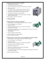
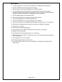
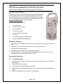
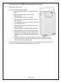
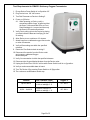
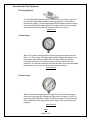
300 Held Drive
Northampton Pa 18067
610.262.6090
August 28, 2012
Recommended testing for verifying device performance.
Intervals of testing are to be set by the Healthcare Provider / Dealer.
Table of Contents
Test Requirements for the Easy Comp (PM50) ..................................................... 2
Test Requirements for the Easy Vac (PM60) ........................................................ 2
Test Requirements for the Power Vac (PM61) ...................................................... 3
Test Requirements for the Power Vac Plus (PM63) .............................................. 3
Test Requirements for the Easy Go Vac (PM65) .................................................. 4
Test Requirements for the MinMate Easy Neb (PM5 / PM6 / PM7) ...................... 4
Test Requirements for the Easy Air (PM15F)........................................................ 4
Test Requirements for the Easy Air (PM15P) ....................................................... 5
Test Requirements for 1600 series regulators. ..................................................... 5
Test Requirements for Easy Pulse Conserving Regulators (188705 & 198705). .. 5
Test Requirements for Flowmeters ....................................................................... 6
Test Requirements for PM106 Oxygen Supply Manifold ....................................... 6
Test Requirements for Vacuum Regulators .......................................................... 7
PM2100 Series Operational Verification Procedure ............................................ 11
PM2200 Series Operational Verification Procedure ............................................ 14
PM2300 Series Operational Verification Procedure ............................................ 17
Test Requirements for PM4150 Portable Oxygen Concentrator ......................... 19
Test Requirements for PM4351 Stationary Oxygen Concentrator ...................... 20
Recommended Test Equipment .......................................................................... 21
Page 1 of 21
Test Requirements for the Easy Comp (PM50)
1. Plug device into power source.
2. Switch power to ON.
3. Attach a calibrated pressure gauge to the outlet port.
4. Set pressure to 50 PSI
5. Verify gauge accuracy is within 2% of full scale.
6. Set pressure to maximum.(valve assembly completely Clockwise)
7. Reading on gauge must be ≥ 85 PSI
8. Power OFF device.
9. Remove pressure gauge.
10. Attach calibrated Flow gauge to valve assembly.
11. Power ON device.
12. Flow must be a ≥ 32 LPM.
13. Switch power to OFF and unplug.
14. Remove Flow gauge.
Test Requirements for the Easy Vac (PM60)
1. Plug device into power source.
2. Remove suction canister assembly.
3. Attach a calibrated vacuum gauge to the device inlet port.
4. Switch power to ON.
5. Set vacuum to 15” InHg on calibrated vacuum gauge.
6. Verify device gauge accuracy is within 2% of full scale.
7. Set vacuum to maximum. (valve assembly completely Clockwise)
8. Reading on gauges must be ≥24” InHg.
9. Switch power to OFF.
10. Remove calibrated vacuum gauge.
11. Attach calibrated Flow gauge to valve assembly.
12. Switch power to ON
13. Flow must be ≥ 29 LPM
14. Switch power to OFF and unplug device.
15. Remove calibrated Flow gauge.
16. Reattach suction canister assembly.
Page 2 of 21
Test Requirements for the Power Vac (PM61)
1. Plug device into power source.
2. Remove suction canister assembly.
3. Attach a calibrated vacuum gauge to the device inlet port.
4. Switch power to ON.
5. Set vacuum to 15” InHg on calibrated vacuum gauge.
6. Verify device gauge accuracy is within 2% of full scale.
7. Set vacuum to maximum.
8. Reading on gauges must be ≥24” InHg.
9. Switch power to OFF.
10. Remove calibrated vacuum gauge.
11. Attach calibrated Flow gauge to device inlet port.
12. Switch power to ON.
13. Flow must be ≥ 22 LPM
14. Switch power to OFF and unplug device.
15. Remove calibrated Flow gauge.
16. Reattach suction canister assembly.
Test Requirements for the Power Vac Plus (PM63)
1. Plug device into power source.
2. Remove suction canister assembly.
3. Attach a calibrated vacuum gauge to the inlet port.
4. Turn device ON.
5. Turn white, selector knob to REG position.
6. Set vacuum to 120 mmHG (4.7” InHg) on calibrated vacuum gauge.
7. Verify device gauge accuracy is with +/- 6 mmHG (.24” InHg)
8. Set vacuum to maximum (grey knob fully clockwise).
9. Measured vacuum shall be within 9 InHg (229 mmHG) to 13
InHg (330 mmHG).
10. Switch power to OFF.
11. Remove calibrated vacuum gauge.
12. Attach calibrated Flow gauge to inlet port.
13. Switch power to ON.
14. Flow must be ≥ 17 LPM
15. Turn selector knob to INT, let device run for 2 min.
16. Ensure needle cycles intermittently between 0 and full vacuum.
17. Turn grey knob counterclockwise until gauge reaches 100 mmHg.
18. Let device run for 2 min.
19. Ensure needle cycles intermittently between 0 and 100 mmHg.
20. Turn device off.
21. Remove calibrated Flow gauge.
22. Reattach suction canister assembly.
Page 3 of 21
Test Requirements for the Easy Go Vac (PM65)
1. Plug device into power source.
2. Remove suction canister assembly.
3. Attach a calibrated vacuum gauge to filter inlet port.
4. Switch power to ON.
5. Set vacuum to 15” InHg on calibrated vacuum gauge.
6. Verify device gauge accuracy is within 2% of full scale.
7. Set vacuum to maximum. (Completely Clockwise).
8. Reading on gauge must be ≥19 InHg.
9. Switch power to OFF.
10. Remove vacuum gauge.
11. Attach calibrated Flow gauge to filter inlet port.
12. Switch power to ON.
13. Flow must be ≥ 12 LPM.
14. Switch power to OFF and unplug.
15. Remove Flow gauge.
16. Reattach suction canister assembly.
17. Also verify the charger for proper operation as indicated in the User Manual.
Test Requirements for the MinMate Easy Neb (PM5 / PM6 / PM7)
1. Plug device into power source.
2. Switch power to ON.
3. Attach a Westmed, Inc. Vixone ® Nebulizer Kit Part# 0210 or equivalent to the output port.
4. Attach a peace of tubing from the output of the Westmed, Inc. Vixone ® Nebulizer orifice to
a calibrated Flowmeter/Gauge
5. Measured output must be ≥ 6 LPM
6. Remove Nebulizer from device.
7. Switch power to OFF and unplug
Test Requirements for the Easy Air (PM15F)
1. Plug device into power source.
2. Turn regulator knob fully counterclockwise.
3. Attach a calibrated flow monitor to the outlet fitting on the PM15F.
4. Switch power to ON.
5. Turn regulator knob until flow monitor reads 5 LPM.
6. Verify reading on device flow gauge is within ± 1 LPM of flow monitor.
7. Turn regulator knob until flow monitor reads 10 LPM.
8. Verify reading on device flow gauge is within ± 1 LPM of flow monitor.
9. Turn regulator knob fully counterclockwise.
10. Switch power to OFF.
11. Remove flow monitor.
Page 4 of 21
Test Requirements for the Easy Air (PM15P)
1. Plug device into power source.
2. Turn regulator knob fully counterclockwise.
3. Attach a calibrated pressure gauge to the outlet fitting on the PM15P.
4. Switch power to ON.
5. Turn regulator knob until calibrated pressure gauge is at 60 PSI
6. Verify device pressure gauge accuracy is within 2% of full scale.
7. If gauge does not reach 60 PSI, Check the device for leaks.
8. Turn regulator knob back until you reach 50 PSI.
9. Remove pressure gauge from outlet fitting and attach a flow gauge
capable of reading 40 LPM.
10. Flow should be a minimum of 30.0 LPM.
11. Remove flow gauge.
12. Switch power to OFF.
Test Requirements for 1600 series regulators.
1. Attach regulator to a USP Oxygen cylinder with a minimum of 500 psi
2. Ensure the regulator is in the off position.
3. Slowly open cylinder.
4. Attached a calibrated flow gauge to the outlet port of the regulator.
5. Set regulator to first setting.
6. Measured flow should be within ±10cc for settings 32.25cc to 125cc, and ±10% of the
indicated setting of 250cc and up
7. Test all settings.
8. Return the regulator to the off position.
9. Close the cylinder and remove flow gauge.
10. Remove regulator from cylinder.
Test Requirements for Easy Pulse Conserving Regulators (188705 & 198705).
1. Attach regulator to a USP Oxygen cylinder with a minimum of 500 psi
2. Ensure the regulator is in the off position.
3. Slowly open cylinder.
4. Attached a calibrated flow gauge to the outlet port of the regulator.
5. Set regulator to the 2 LPM Continuous setting.
6. Measured flow should be ±10%
7. Remove the flow gauge from the outlet port of the regulator
8. Return the regulator to the off position.
9. To test the pulse settings, ensure the device triggers when an inspiratory breath is taken
with a cannula connected.
10. Remove regulator from cylinder.
Page 5 of 21
Test Requirements for Flowmeters
1. Inspect product for visible damage. Remove from service if any damage is found.
2. Turn control knob fully clockwise to the OFF position.
3. Connect the device to the appropriate gas source. The appropriate gas and pressure
are specified on the Flow Tube.
4. Verify that the Float Ball is at the very bottom of the Flow Tube.
NOTE: If the Float is not resting at the bottom of the Flow Tube, the device may be
leaking; consult the Troubleshooting Guide.
5. Connect a calibrated flow measuring device to the outlet of the flowmeter.
6. Ensure the flow measuring device is set to the correct gas type.(Oxygen or Air)
7. Divide the scale into three even divisions. (Low, Middle, and High)
8. Set the flow to the Low value by aligning center of Float Ball with indicator line on the
Flowtube.
9. Ensue the accuracy of the flowmeter is within the specifications stated in the user manual.
10. Repeat step 8 & 9 for the Middle & High values.
Test Requirements for PM106 Oxygen Supply Manifold
1. Attach PM106 O2 Supply Manifold to a 50 psi (+/- .25 psi)
oxygen source.
2. For each of the six valves, perform the following test:
A. Attach one end of tubing to the tubing nipple; attach
other end of tubing to a calibrated flowmeter.
B. Turn Control Knob to 5 LPM setting and check the flowrate (must be 5 +/-1 LPM)
C. Turn knob fully open and check the flow-rate (must be
equal to or greater than 18 LPM)
Page 6 of 21
Test Requirements for Vacuum Regulators
Models PM3000 / PM3500
1. Connect regulator to a vacuum source capable of 21 InHg @ 100
LPM minimum.
2. Set selector on regulator to "REG" position.
3. Turn the regulator knob clockwise, then counterclockwise and
ensure the gauge reaches full vacuum and also that it returns
back to zero, ensuring a smooth correlation between turning the
knob and the corresponding needle movement.
4. Connect a calibrated vacuum gauge to the inlet port.
5. Set the regulator gauge to 60 mmHg and ensure the calibrated vacuum gauge reading
is 60 mmHg ± 4.
6. Set the regulator gauge to 140 mmHg and ensure the calibrated vacuum gauge reading
is 140 mmHg ± 4.
7. For PM3000 only: Set the regulator gauge to 200 mmHg and ensure the calibrated
vacuum gauge reading is 200 mmHg ± 6.
8. For PM3500 only: Set the regulator knob fully clockwise and ensure the calibrated
vacuum gauge reading is 170 mmHg ± 10.
9. Disconnect the calibrated vacuum gauge.
10. Attach a calibrated flow gauge.
11. Turn knob on regulator fully clockwise.
12. Verify flow is ≥ 51 LPM.
13. Disconnect the calibrated flow gauge.
14. Turn knob on regulator fully counterclockwise.
15. Ensure gauge returns to zero.
16. If any of the above checks do not meet specifications, troubleshoot device.
17. Turn regulator OFF position.
18. Disconnect regulator from vacuum source.
Page 7 of 21
Model PM3100
1. Connect regulator to a vacuum source capable of 21 InHg @ 100 LPM minimum.
2. Set the selector on the vacuum regulator to the "REG" position.
3. Turn the regulator knob clockwise, then counterclockwise and ensure the gauge
reaches full vacuum and also that it returns back to zero, ensuring a smooth correlation
between turning the knob and the corresponding needle movement.
4. Connect a calibrated vacuum gauge to the inlet port.
5. Set the regulator gauge to 60 mmHg and ensure the calibrated vacuum gauge reading
is 60 mmHg ±4.
6. Set the regulator gauge to 140 mmHg and ensure the calibrated vacuum gauge is 140
mmHg ±4.
7. Set the regulator gauge to 200 mmHg and ensure the calibrated vacuum gauge reading
is 200 mmHg ±6.
8. Disconnect the calibrated vacuum gauge.
9. Attach a calibrated flow gauge.
10. Turn knob on regulator fully clockwise.
11. Verify flow is ≥ 51 LPM.
12. Set the selector on the vacuum regulator to the "LINE" position.
13. Verify flow is ≥ 55 LPM.
14. Turn regulator to the OFF position.
19. Disconnect the calibrated flow gauge.
15. Turn knob on regulator fully counterclockwise.
16. Disconnect regulator from vacuum source.
17. If any of the above checks do not meet specifications, then troubleshoot the device.
Page 8 of 21
Model PM3300
1. Connect regulator to a vacuum source capable of 21 InHg @ 100 LPM
minimum.
2. Set the selector on the Vacuum Regulator to the "REG" position.
3. Turn the regulator knob clockwise, then counterclockwise and ensure the
gauge reaches full vacuum and also that it returns back to zero, ensuring a
smooth correlation between turning the knob and the corresponding needle
movement.
4. Connect a calibrated vacuum gauge to the inlet port.
5. Set the regulator gauge to 60 mm/Hg.
6. Ensure the calibrated vacuum gauge reading is 60 mm/Hg ±4.
7. Set the regulator gauge to 140 mm/Hg.
8. Ensure the calibrated vacuum gauge reading is 140 mm/Hg ±4.
9. Set the regulator gauge to 200 mm/Hg.
10. Ensure the calibrated vacuum gauge reading is 200mm/Hg ±6.
11. Disconnect the calibrated vacuum gauge.
12. Attach a calibrated flow gauge.
13. Turn knob on regulator fully clockwise.
14. Verify flow is ≥ 51 LPM.
15. Disconnect the calibrated flow gauge.
16. Set the regulator gauge to 180 mm/Hg.
17. Switch to the "INT" position.
18. Timing Module should engage between 6 to 10 seconds.
19. When the device clicks "ON", needle should return to 180 mm/Hg and remain steady for
14 to 18 seconds.
20. Turn Regulator to the "OFF" position.
21. Disconnect regulator from vacuum source.
22. If any of the above checks do not meet specification, troubleshoot the device and/or
adjust timing.
Page 9 of 21
Model PM3400
1. Connect regulator to a vacuum source capable of 21 InHg @ 100 LPM minimum.
2. Connect a calibrated vacuum gauge to the inlet port.
3. Set the selector on the vacuum regulator to the "REG" position.
4. Turn the regulator knob clockwise, then counterclockwise and ensure the gauge
reaches full vacuum and also that it returns back to zero, ensuring a smooth correlation
between turning the knob and the corresponding needle movement.
5. Set the regulator gauge to 60 mmHg (8 KPa).
6. Ensure the calibrated vacuum gauge reading is 60 mmHg ±4.
7. Set the regulator gauge to 140 mmHg (18-20 KPa).
8. Ensure the calibrated vacuum gauge reading is 140 mmHg ±4.
9. Turn the Vac device up to maximum (fully clockwise); verify max vac is 170 mmHg ±10.
10. Disconnect the calibrated vacuum gauge and connect a calibrated flow gauge.
11. Verify flow is ≥ 50 LPM.
12. Disconnect the calibrated flow gauge.
13. Place the device in the "REG" position and set the needle to 120 mmHg.
14. Switch to the "INT" position.
15. Timing Module should engage between 6 to 10 seconds.
16. When the device clicks "ON", needle should return to 120 mmHg and remain steady for
14 to 18 seconds.
17. Turn Regulator to the "OFF" position.
18. Disconnect regulator from vacuum source.
19. If any of the above checks do not meet specification, troubleshoot the device and/or
adjust timing.
Page 10 of 21
PM2100 Series Operational Verification Procedure
(Please refer to EasyMate PM2100 Series User Manuals available at http://www.precisionmedical.com/homecare/liquid-oxygen-systems/pm2100-easymate-lox for
instructions in other languages.)
These procedures are to verify the proper function of the PM2100 Series
Liquid Oxygen portable device. Any functional problems found during
these inspections must be corrected before returning device to service.
Prior to performing these procedures, read and understand the PM2100
Series User Manual available on the Website @
www.precisionmedical.com.
The following shall be performed:
1.
Visual inspection
2.
Function test of the scale
3.
Vent-to-Fill check
4.
Fill Connector check
5.
Pressure Relief Valves check
6.
Flow test
7.
Pulse and Trigger check (PM2120 only)
8.
Normal Evaporation Rate (NER) test
Equipment Required:
1. A compatible Liquid Oxygen Reservoir (base device) between 18 psi to 26 psi (1.24 to 1.80
bar)
2. Maximum 7 foot long standard adult single lumen oxygen nasal cannula.
3. Calibrated flow measuring device.
4. User Manual for the PM2100 Series Liquid Oxygen System.
5. For NER test ONLY, a calibrated weight scale capable of measuring at least up to 9 lbs
(4.08 kg) with resolution of at least 1/100 oz (1/10 g).
Inspection Procedures:
1.0
Visual Inspection
1.1
Insure the device is empty (if device has not been filled in the past 12 hours it is empty of
liquid oxygen)
1.2
Remove device from carry bag.
1.3
Inspect the device for any damaged components.
1.4
Verify that labels are still adhering properly to the device; and all warnings and labels are
legible.
1.5
Inspect the Carry Bag for any damage or missing straps.
Page 11 of 21
2.0
Scale Test
2.1
Release the Scale from is stowed position as per the User Manual.
2.2
Lift the Scale with one hand and pull down the device with the other hand until the Scale
reads “Full”, release the device. The Scale should read “Empty”, return Scale to its stowed
position.
2.3
Fill the device and attach release the Scale from its stowed position as per the User
Manual.
2.4
Lift the Scale in one hand and pull down on the device with the other until the Scale reads
“Full”, release the device. The Scale should read “Full”.
2.5
If the Scale fails step 2.2 and 2.4 replace the scale.
3.0
Vent-to-Fill Inspection
3.1
Fill the device as per User Manual. During the filling process observe if any leakage
around the Vent to Fill Lever and that it opens and closes smoothly.
3.2
If after 5 minutes, oxygen continues to vent through the vent tube nest to the fill
connector, installation of a new Vent -to -Fill Valve is necessary; use P/N 507317.
4.0
Fill Connector Inspection
4.1
During the filling process observe if any leakage is coming from the Fill Connector.
4.2
If leaking is observed from a PM2100 (PB) Fill Connector replacement of lip seal is
needed; use P/N 504003.
4.3
Wait 10 seconds after filling, Inspect for leaks from the Fill Connector.
If leakage is found repair as needed:
5.0
Pressure Relief Valve Test
5.1
After filling, let the device set for 10 minutes. During this time, observe for excessive
continuous venting (some venting is normal). If excessive venting is observed, installation
of a new Pressure Relief Valve may be necessary; use P/N 504993.
5.2
After 5 minutes, agitate device. There should be an increase in the venting of gaseous
oxygen. If there is no venting after agitation, installation of a new Pressure Relief Valve is
necessary, use P/N 504993.
6.0
Flow Test.
6.1
Attached a calibrated flow measuring device to the outlet fitting of the PM2100 series
portable. Set the flow setting knob to “1 l/min”. Flow should be within flow specification of
+/- 15% of setting. Repeat on all additional continuous flow settings.
6.2
If the flow is below specification the device may have been overfilled and may require time
to warm and build pressure. Adjust to setting “0”. Wait 15 minutes and repeat step 6.1. If
flow is still below specification, check the flow measuring device for proper calibration and
that it is properly connected to the device under test.
Page 12 of 21
7.0
Pulse Delivery and Trigger Test (PM2120 EasyMate6+6 only)
7.1
Follow User Manual for attaching cannula.
7.2
Adjust to setting “1”. Breathing normal, you should notice a small pulse at the beginning of
each breath. Repeat on setting “2 thru 4”.
7.3
If the device fails to trigger at any of the settings, device may have been overfilled and
may require time to warm and build pressure. Adjust to setting “0”. Wait 15 minutes and
repeat step 7.1 and 7.2. If device still fails to trigger, check the cannula for proper
connection and position in the nose. If the device still fails to trigger contact Precision
Medical.
8.0
Normal Evaporation Rate (NER) Test
This test shall be performed when the device exhibits the following symptoms:
a) Lower than normal durations (use time).
b) Frost on the Label (container).
c)
Excessive venting of gaseous oxygen from the Pressure Relief Valve.
8.1
Prior to performing the NER test, confirm that the Fill Connector, Vent-to-Fill valve, and
Pressure Relief Valve are not leaking.
8.2
Set the setting knob to setting “0”, fill as per User Manual and wait for 1 hour.
8.3
Weigh the device using calibrated weight scale and record weight and time.
8.4
Wait approximately 10 minutes and weigh the device again and record weight and time.
8.5
Calculate the NER by using the following formula:
Weight Change (ounces or grams)
Elapsed Time (minutes)
8.6
Confirm that the NER is 0.047 ounces or 1.33 grams per minute (1.0 LPM) or less. If the
NER is greater than 0.047 ounces, repeat these steps 8.1 through 8.5. If the device’s
NER is still greater, contact Precision Medical.
Page 13 of 21
PM2200 Series Operational Verification Procedure
(Please refer to EasyMate PM2200 Series Service Kit Manuals available at http://www.precisionmedical.com/homecare/liquid-oxygen-systems/pm2200easymate-lox for instructions in other languages.)
These procedures are to verify the proper function of the PM2200 Series
Liquid Oxygen System portable device. Any functional problems found
during these inspections must be corrected before returning device to
service.
Prior to performing these procedures, read and understand the PM2200
Series User Manual; available on the Website @
www.precisionmedical.com.
The following shall be performed:
1. Visual inspection
2. Function test of the scale
3. Vent-to-Fill check
4. Fill Connector check
5. Pressure Relief Valves check
6. Pulse and Trigger check
7. Normal Evaporation Rate (NER) test
Equipment Required:
1. A compatible Liquid Oxygen Reservoir (base device) between 22 psi to 50 psi.
2. Maximum 7 foot long standard adult single lumen oxygen nasal cannula.
3. User Manual for the PM2200 Series Liquid Oxygen System.
4.
For NER test ONLY, a calibrated weight scale capable of measuring at least up to 5
lbs (2.27 kg) with resolution of at least 1/100 oz (1/10 g).
Inspection Procedures:
1.0
Visual Inspection
1.1
Insure the device is empty (if device has not been filled in the past 12 hours it is
empty of liquid oxygen)
1.2
Remove device from bag.
1.3
Inspect the device for any damaged components.
1.4
Verify that labels are still adhering properly to the device; and all warnings and
labels are legible.
1.5
Tug on each end of handle to ensure that the handle is still fully inserted in the
mating slots and properly secured to the top of the device. If replacement is
needed, use P/N 504507.
1.6
Inspect the Carry Bag, special attention to white felt liner (P/N 504488) and
mesh on bottom. If replacement is needed, use P/N 504392.
Page 14 of 21
2.0
3.0
4.0
Scale Test
2.1
Attach the Scale as per the User Manual.
2.2
Lift the Scale with one hand and pull down the device with the other hand until
the Scale reads “Full” , release the device. The Scale should read “Empty”
, remove Scale.
2.3
Fill the device and attach the Scale as per the User Manual.
2.4
Lift the Scale in one hand and pull down on the device with the other until the
Scale reads “Full” , release the device. The Scale should read “Full” .
2.5
If the Scale fails step 2.2 and 2.4 replace the scale.
Vent-to-Fill Inspection
3.1
Fill the device as per User Manual. During the filling process observe if any
leakage around the Vent to Fill Lever and that it opens and closes smoothly.
3.2
If after 5 minutes, oxygen continues to vent through the vent tube, installation of
a new Vent -to -Fill Valve is necessary; use P/N 504505.
Fill Connector Inspection
4.1
During the filling process observe if any leakage is coming from the Fill
Connector.
4.2
If leaking is observed from a PM2200 (PB) Fill Connector replacement of lip seal
is needed; use P/N 504503.
10 seconds after filling Inspect for leaks from the Fill Connector.
If leakage is found repair as needed:
PB & Taema Fill Connector Service Kits
(PB Connector is silver without pins) P/N 504504
(Taema Connector is black without pins) P/N 504853
Mark Series Fill Connector Service Kit
(Connector has pin and black ring at outer end) P/N 504709
Caire Series Fill Connector Service Kit
(Connector is silver with a pin on the top and in front) P/N 504853
5.0
Pressure Relief Valve Test
5.1
After filling the device, let device set for 10 minutes. During this time, observe
for excessive continuous venting (some venting is normal). If excessive venting
is observed, installation of a new Pressure Relief Valve may be necessary; use
P/N 504506.
5.2
After 5 minutes, agitate device. There should be an increase in the venting of
gaseous oxygen. If there is no venting after agitation, installation of a new
Pressure Relief Valve is necessary, use P/N 504506.
Page 15 of 21
6.0
7.0
Pulse Delivery and Trigger Test
6.1
Follow User Manual for attaching cannula.
6.2
Adjust to setting “1”. Breathing normal, you should notice a small pulse at the
beginning of each breath. Repeat on setting “2 thru 4”.
6.3
If the device fails to trigger at any of the settings, device may have been
overfilled and may require time to warm and build pressure. Adjust to setting “0”.
Wait 15 minutes and repeat step 6.1 and 6.2. If device still fails to trigger, check
the cannula for proper connection and position in the nose. If the device still fails
to trigger contact Precision Medical.
Normal Evaporation Rate (NER) Test
This test shall be performed when the device exhibits the following symptoms:
a) Lower than normal durations (use time).
b) Frost on the Label (container).
c) Excessive venting of gaseous oxygen from the Pressure Relief Valve.
7.1
Prior to performing the NER test, confirm that the Fill Connector, Vent-to-Fill
valve, and Pressure Relief Valve are not leaking.
7.2
Set the Pulse Selector to setting “0”, fill as per User Manual and wait for 1.5
hours.
7.3
Weigh the device using calibrated weight scale and record weight and time.
7.4
Wait for 1 hour, and then weigh the device again and record weight and time.
7.5
Calculate the NER by using the following formula:
Weight Change (ounces or grams)
Elapsed Time (hour)
7.6
Confirm that the NER is 1.53 ounces or 43.38 grams per hour (0.55 LPM) or
less. If the NER is greater than 1.53, repeat these steps 7.1 through 7.5. If the
device’s NER is still greater, contact Precision Medical.
Page 16 of 21
PM2300 Series Operational Verification Procedure
The following inspection procedures are used to verify proper
functioning of a PM2300 Series EasyMate Reservoir. Any
problems found during these inspections should be corrected
prior to placing EasyMate Reservoir back in service. In addition to
these procedures, read and understand the PM2300 Series
EasyMate Reservoir User Manual.
Procedures:
1. Visual / Functional Inspection
2. Pressure Relief Valves check
3. Fill Connector check
4. Function test of the Liquid Level Indicator
5. Maximum Flow Check
6. Normal Evaporation Rate (NER) test
Equipment Required:
1. A Medical Grade Liquid Oxygen source greater than 23
psig (1.59 bar).
2. Vent-to-Fill tool (PN 505400)
3. Medical gaseous oxygen source, 0-30 psig (0-2.07 bar)
4. User Manual for the PM2300 Series EasyMate Reservoir.
5. Flow measuring device capable of measuring up to 9 LPM.
6. For NER Procedure requires a calibrated weight scale with a minimum range to 90 lbs
(33.60 kg) with a resolution of .01 lbs.
7.
A 0-30 psig (2.07 bar) test pressure gauge with oxygen DISS.
Procedures:
1 Visual / Functional Inspection
1.1.
Visually inspect the EasyMate Reservoir for damage or missing components.
1.2.
Verify that the following labels are present and legible:
a) Fill Connector label
b) Liquid Level Indicator label
c) Outlet Connection label
d) Warning label
e) Serial Number label
1.3.
Verify the Liquid Level Indicator is functioning when activated.
NOTE: A flashing bottom light for a half a second ”ON” and a half second “OFF”
for an eight second duration, the battery needs to be replaced.
1.4.
Verify that the Fill Connector is not worn, leaking, or damaged.
1.5.
Using the Vent-to-Fill tool, open and close the Vent Valve verifying functionality.
1.6.
Verify that the Condensation Collection Container is in place and empty.
Page 17 of 21
2 Pressure Relief Valves check
2.1.
Attach a test pressure gauge to the DISS outlet.
2.2.
Connect the oxygen pressure source to the test pressure gauge.
2.3.
Pressurize the EasyMate Reservoir to 20 psig (1.38 bar). Confirm that no venting
is heard from the EasyMate Reservoir. If venting is heard, the EasyMate
Reservoir requires service.
2.4.
Pressurize Reservoir to 25 psig (1.72 bar). Confirm that an audible venting sound
exists at the pressure relief valves. If no venting is heard, the EasyMate Reservoir
requires service.
3 Fill Connector check
3.1.
With EasyMate Reservoir still pressurized, use oxygen safe leak detector to
determine if the Fill connector is leaking. If leakage is MAJOR, the EasyMate
Reservoir requires service.
4 Liquid Level Indicator test
4.1.
Fill EasyMate Reservoir with 20 - 30 lbs (7.46 - 11.20 kg) of Liquid Oxygen while
maintaining a saturation pressure of at least 20 psig (1.38 bar). (Total weight 71 to
81 lbs for 45 Liter Reservoir.)
4.2.
Allow Reservoir to stand for one (1) minute after filling.
4.3.
Activate the Liquid Level Indicator and verify that at least one (1) light is
illuminated. If not, the EasyMate Reservoir requires service.
4.4.
Verify that no frost or heavy condensation is present on the container below the
plastic shroud.
5 Maximum Flow Check
5.1.
Connect a flow metering device to the Oxygen DISS Outlet Connection of the
EasyMate Reservoir.
5.2.
Verify flow is 8 LPM ±1 LPM. Monitor the flow for 10 minutes and verify the flow is
still within the specification. If flow is out of specification, the EasyMate Reservoir
requires service.
6 Normal Evaporation Rate (NER) test
This test shall be performed when the Reservoir exhibits any of the following symptoms:
a) Lower than normal durations (use time).
b) Frost on the container.
6.1.
Let Reservoir set undisturbed for 24 hours.
6.2.
Place Reservoir on the calibrated scale.
6.3.
Record time and weight of Reservoir.
6.4.
Let Reservoir set undisturbed for another 24 hours.
6.5.
Record time and weight of Reservoir.
Calculate the NER with the following formula:
(Weight change (lbs.) / Elapsed Time (hours)) X 24
The NER must be ≤ 1.54 lbs/Day.
6.6.
If NER is greater, allow EasyMate Reservoir to set undisturbed for another 24
hours.
6.7.
Again record time and weight of Reservoir.
6.8.
Recalculate the NER using the readings from steps 6.5 and 6.7.
6.9.
If NER fails second time, the EasyMate Reservoir requires service.
Page 18 of 21
Test Requirements for PM4150 Portable Oxygen Concentrator
Checking the Oxygen Purity
Put the EasyPulse POC in Test Mode*
1. Attach the EasyPulse POC to an oxygen purity test
device.
2. Remove all external power sources to the
EasyPulse POC.
3. Turn EasyPulse POC off for 15 seconds.
4. Then, like a combination lock, turn dial to: 5, then 1,
then 3, then off.
5. Turn EasyPulse POC to any flow setting. The device
will continuously pulse.
6. The alarm LED on the front will blink yellow and red
while in test mode.
(Steps 3 & 4 must be completed within 8 seconds)
7. Attach external power source to the POC if needed.
8. In this mode, you can go to any flow setting and test
oxygen purity. The EasyPulse POC will pulse as if it
was attached to a simulator breathing 20 breaths per
minute.
9. To return EasyPulse POC to normal function, turn dial to off position. Once the
device is turned to the off position, you will need to go through the above steps to
get the device back into the test mode.
*It is very important to remove any external power source and allow the EasyPulse POC to sit
for at least 15 seconds before attempting to put in to the test mode.
Page 19 of 21
Test Requirements for PM4351 Stationary Oxygen Concentrator
1. Ensure Device Power Switch is in off position “O”.
2. Plug Device into a 120 VAC source.
3. Turn Dial Flowmeter on Device to Setting 5.
4. Power on (I) Device.
4.1. When powering on Device, verify a
momentary audible “beep” is heard and that
the Green, Yellow and Red LEDs on Front
Panel illuminate for 1 second and then only
the Green LED remains illuminated.
5. Verify Fan is pulling air into the Device by placing
your hand under the Base and verifying you feel
air moving.
6. Allow Device to run a minimum of 3 minutes.
7. Attach hose from a calibrated oxygen flow monitor
to outlet of flowmeter.
8. Verify all flow settings are within the specified
tolerance.
9. Return the Flow Selector back to setting 5.
10. Disconnect flow monitor from the Device outlet
and connect a calibrated Oxygen
Monitor/Analyzer.
11. Verify O2 concentration is within the specified tolerance.
12. Disconnect the Oxygen Monitor/Analyzer from the Device outlet.
13. Unplug the Device from 120 VAC source while Power Switch is still in on (I) position.
14. Verify a continuous audible alarm is heard.
15. Turn The Device off by pressing Power Switch to off (O) position.
16. The continuous audible alarm should stop.
*Altitude
Up to 6,500 ft
6,501 - 10,000 ft
Flow Tolerance (l/min)
Oxygen %
± 200 ml settings 0.5 -1.5
± 10% of settings 2 - 5
87 - 95 %
± 200 ml settings 0.5
± 20% of settings 1 - 5
85 - 90 %
Page 20 of 21
Recommended Test Equipment
Flow Gauge/Monitor
The TSI Model 4040 Mass Flowmeter can be used for a multitude of gas flow
measurement applications. Whether measuring gas flows in a laboratory or
manufacturing setting, TSI general-purpose mass flowmeters provide accurate
results with multiple data output options. The display versions come complete
with accessories making setup and operation fast and convenient.
www.tsi.com
Vacuum Gauge
Wika 332.34 series industrial quality precision test gauges measure Vacuum
within +/- 0.25% of span. Solid front, blow-out-back rugged thermoplastic case
meets safety requirements of ASME B40.100. Internal parts and process
connection are made of 316 stainless steel, providing excellent corrosion
resistance. The dial has a reflective mirrored band with a micrometer adjustable
knife-edge pointer for easy-to-read accurate pressure readings.
www.wika.com
Pressure Gauge
Wika 4" Inspector's test gauges are the logical choice for precision pressure
testing and convenient field calibrations. High precision accuracy of 0.25% of
span meets rigid ASME B40.1 Grade 3A quality standards. The mirrored band
on the dial and the knife-edge pointer make it easy to take accurate pressure
readings.
www.wika.com
END
Page 21 of 21