1
Managing Data Center
Connectivity
Version 1.0
• Defining your environment and requirements
• EMC Connectrix Manager Converged Network Edition (CMCNE)
• Brocade Network Advisor (BNA)
• Cisco Data Center Network Manager (DCNM)
Todd Bolton
Mark Anthony P. De Castro
Avan Cheng Kian Meng
Copyright © 2012 EMC Corporation. All rights reserved.
EMC believes the information in this publication is accurate as of its publication date. The information is
subject to change without notice.
THE INFORMATION IN THIS PUBLICATION IS PROVIDED “AS IS.” EMC CORPORATION MAKES NO
REPRESENTATIONS OR WARRANTIES OF ANY KIND WITH RESPECT TO THE INFORMATION IN THIS
PUBLICATION, AND SPECIFICALLY DISCLAIMS IMPLIED WARRANTIES OF MERCHANTABILITY OR
FITNESS FOR A PARTICULAR PURPOSE.
Use, copying, and distribution of any EMC software described in this publication requires an applicable
software license.
For the most up-to-date regulatory document for your product line, go to the Technical Documentation and
Advisories section on EMC Powerlink.
For the most up-to-date listing of EMC product names, see EMC Corporation Trademarks on EMC.com.
All other trademarks used herein are the property of their respective owners.
Part number H8081
2
SAN Management TechBook
Contents
Preface.............................................................................................................................. 7
Chapter 1
Introduction to Managing Data Center Connectivity
Introduction .......................................................................................
Defining your environment.............................................................
Local Area Network (LAN)......................................................
Storage Area Network (SAN) ..................................................
Converged network...................................................................
Virtualization .............................................................................
Defining your requirements ............................................................
Software management tools ............................................................
Chapter 2
14
15
16
16
17
18
19
20
CMCNE and BNA
EMC Connectrix Manager Converged Network Edition ...........
Licensing .....................................................................................
User interface..............................................................................
Components ...............................................................................
New features ..............................................................................
References ...................................................................................
Brocade Network Advisor...............................................................
Licensing .....................................................................................
BNA Dashboard.........................................................................
Brocade VDX switches ..............................................................
Brocade VCS Fabric technology ..............................................
Ethernet fabrics ..........................................................................
References ...................................................................................
Using CMCNE and BNA to manage data center
connectivity........................................................................................
SAN Management TechBook
24
25
26
27
33
40
41
41
41
42
43
44
46
47
3
Contents
Network management .............................................................. 47
IP features ................................................................................... 52
Chapter 3
Cisco DCNM
DCNM ................................................................................................
Licensing .....................................................................................
Views ...........................................................................................
Web-based interface (Dashboard) ..................................................
DCNM-SAN ......................................................................................
Licensing .....................................................................................
Views ...........................................................................................
Benefits........................................................................................
Components ...............................................................................
Features .......................................................................................
References ...................................................................................
DCNM-LAN......................................................................................
Licensing .....................................................................................
Views ...........................................................................................
Benefits........................................................................................
Component .................................................................................
Features .......................................................................................
References ...................................................................................
Chapter 4
56
57
57
59
66
66
68
68
69
69
77
78
78
79
80
80
80
89
Choosing A Software Management Tool
Considerations in choosing a tool ..................................................
Decision makers................................................................................
Scalability...........................................................................................
Can this tool scale to larger environments?...........................
Installation .........................................................................................
Is the product easy to install? ..................................................
Ease of use..........................................................................................
Is the product easy to use? .......................................................
Out-of-the-box...................................................................................
Can I use this product straight out of the box? .....................
Customization ...................................................................................
Can it be customized? ...............................................................
92
93
94
94
95
95
96
96
97
97
98
98
Glossary ......................................................................................................................... 99
4
SAN Management TechBook
Figures
Title
1
2
3
4
5
6
7
8
9
10
11
12
13
14
15
16
17
18
19
20
21
22
23
24
25
26
27
28
29
30
Page
FCoE, Bridging the LAN and SAN ..............................................................
CMCNE View All ...........................................................................................
CMCNE Main window .................................................................................
CMCNE Discover Fabrics and Add Fabric Discovery dialog box ..........
CMCNE Zoning dialog box, Zone DB Operation drop-down men .......
Monitoring alerts ............................................................................................
Real time performance graph .......................................................................
Historical performance graph ......................................................................
CMCNE Top Taler dialog box ......................................................................
Logical Switches dialog box ..........................................................................
Diagnostic Port test dialog box ....................................................................
Connection utilization ...................................................................................
Connection utilization legend ......................................................................
Real time performance graphs dialog .........................................................
Brocade Network Advisor Dashboard .......................................................
Brocade VCS Fabric technology ...................................................................
Hierarchical Ethernet compared to Ethernet Fabric architecture ...........
DCB configuration .........................................................................................
Enable 802.1x configuration ..........................................................................
Configuration dialog box ..............................................................................
Brocade Network Advisor Traffic analyzer ...............................................
IP features under the IP tab ..........................................................................
CMCNE IP accessible features .....................................................................
DCNM-SAN Dashboard summary view ....................................................
Event drill down .............................................................................................
Using mouse-over in Performance view .....................................................
Switch CPU performance ..............................................................................
Host Port performance ..................................................................................
Module inventory ...........................................................................................
DCNM-SAN option in Data Center Network Manager ...........................
SAN Management TechBook
15
24
26
28
29
31
32
33
35
36
37
38
38
39
42
44
45
49
50
51
52
53
54
60
61
62
63
64
65
67
5
Figures
31
32
33
34
35
36
37
38
39
40
41
42
43
44
45
46
47
6
Discover dialog box .......................................................................................
DCNM-SAN main window ..........................................................................
DCNM-SAN Zoning view ............................................................................
Alerts in the Main window ...........................................................................
Alerts in the Device Manager view .............................................................
Monitoring environment health using DCNM-SAN Dashboard ...........
Device Manager performance monitor .......................................................
Performance monitoring using DCNM-SAN Dashboard ........................
DCNM-LAN main view ................................................................................
VLAN configuration in DCNM-LAN .........................................................
FIP Snooping Wizard ....................................................................................
Gateway redundancy features .....................................................................
Layer 2 security features, DCNM-LAN ......................................................
Network Analysis wizard .............................................................................
Network inventory in DCNM-LAN ............................................................
DCNM Help ....................................................................................................
DCNM-LAN option in Data Center Network Manager ..........................
SAN Management TechBook
70
71
72
73
74
75
76
77
79
81
82
83
84
85
86
87
88
Preface
This EMC Engineering TechBook provides insight and understanding of
some options available for managing your data center connectivity,
including information on some new software management tools developed to
bridge the gap in the I/O consolidation environment.
E-Lab would like to thank all the contributors to this document, including
EMC engineers, EMC field personnel, and partners. Your contributions are
invaluable.
As part of an effort to improve and enhance the performance and capabilities
of its product lines, EMC periodically releases revisions of its hardware and
software. Therefore, some functions described in this document may not be
supported by all versions of the software or hardware currently in use. For
the most up-to-date information on product features, refer to your product
release notes. If a product does not function properly or does not function as
described in this document, please contact your EMC representative.
Audience
EMC Support Matrix
and E-Lab
Interoperability
Navigator
This TechBook is intended for EMC field personnel, including
technology consultants, and for the storage architect, administrator,
and operator involved in acquiring, managing, operating, or
designing data center connectivity.
For the most up-to-date information, always consult the EMC Support
Matrix (ESM), available through E-Lab Interoperability Navigator
(ELN), at http://elabnavigator.EMC.com, under the PDFs and
Guides tab.
The EMC Support Matrix links within this guide will take you to
Powerlink where you are asked to log in to the E-Lab Interoperability
Navigator. Instructions on how to best use the ELN (tutorial, queries,
wizards) are provided below this Log in window. If you are
SAN Management TechBook
7
Preface
unfamiliar with finding information on this site, please read these
instructions before proceeding any further.
Under the PDFs and Guides tab resides a collection of printable
resources for reference or download. All of the matrices, including
the ESM (which does not include most software), are subsets of the
E-Lab Interoperability Navigator database. Included under this tab
are:
◆
The EMC Support Matrix, a complete guide to interoperable, and
supportable, configurations.
◆
Subset matrices for specific storage families, server families,
operating systems or software products.
◆
Host connectivity guides for complete, authoritative information
on how to configure hosts effectively for various storage
environments.
Under the PDFs and Guides tab, consult the Internet Protocol pdf
under the "Miscellaneous" heading for EMC's policies and
requirements for the EMC Support Matrix.
Related
documentation
Related documents include:
◆
The former EMC Networked Storage Topology Guide has been
divided into several TechBooks and reference manuals. The
following documents, including this one, are available through
the E-Lab Interoperability Navigator, Topology Resource Center
tab, at http://elabnavigator.EMC.com.
These documents are also available at the following location:
http://www.emc.com/products/interoperability/topology-resource-center.htm
• Backup and Recovery in a SAN TechBook
• Building Secure SANs TechBook
• Extended Distance Technologies TechBook
• Fibre Channel over Ethernet (FCoE) Data Center Bridging (DCB)
Case Studies TechBook
• Fibre Channel over Ethernet (FCoE): Data Center Bridging (DCB)
Concepts and Protocols TechBook
• Fibre Channel SAN Topologies TechBook
• iSCSI SAN Topologies TechBook
• Networked Storage Concepts and Protocols TechBook
8
SAN Management TechBook
Preface
• Networking for Storage Virtualization and RecoverPoint TechBook
• WAN Optimization Controller Technologies TechBook
• EMC Connectrix SAN Products Data Reference Manual
• Legacy SAN Technologies Reference Manual
• Non-EMC SAN Products Data Reference Manual
◆
EMC Support Matrix, available through E-Lab Interoperability
Navigator at http://elabnavigator.EMC.com > PDFs and Guides
◆
RSA security solutions documentation, which can be found at
http://RSA.com > Content Library
All of the following documentation and release notes can be found at
http://Powerlink.EMC.com. From the toolbar, select Support >
Technical Documentation and Advisories, then choose the
appropriate Hardware/Platforms, Software, or Host
Connectivity/HBAs documentation links.
The following E-Lab documentation is also available:
◆
◆
Host Connectivity Guides
HBA Guides
For Cisco and Brocade documentation, refer to the vendor’s website.
◆
◆
Authors of this
TechBook
http://cisco.com
http://brocade.com
This TechBook was authored by Todd Bolton with contributions from
EMC engineers, EMC field personnel, and partners.
Todd Bolton is a Senior Systems Integration Engineer and has been
with EMC since 1997. For the past several years, Todd has worked in
the E-Lab qualifying existing EMC SAN software with new Fibre
Channel switch hardware, firmware, and storage management
applications. Prior to E-Lab, Todd worked for the EMC Executive
Briefing Center, demonstrating new products to customers.
Avan Cheng Kian Meng is a Senior Systems Integration Engineer in
EMC E-Lab with over 9 years of experience in the IT storage and
security industry. Before joining EMC in 2008, Avan has held
Technical Specialist roles in the Ministry of Home Affairs in
Singapore. Avan holds a Bachelor's degree in Computing and
Information Systems. He is also a VMware Certified Professional
(VCP) and is IT Infrastructure Library v3 (ITIL v3) certified.
SAN Management TechBook
9
Preface
Mark Anthony P. De Castro is a Senior System Integration Engineer
in EMC E-Lab with over 9 years of experience in the networking
industry, including engineering, provisioning, implementation, and
support roles. Prior to joining EMC in 2008, Mark worked at the Cisco
Technical Assistance Center, AT&T in Singapore, and BT in
Singapore. He holds a Bachelor's degree in Computer Science and is a
Cisco Certified Network Professional (CCNP) and Cisco Certified
Internet Professional (CCIP).
Conventions used in
this document
!
EMC uses the following conventions for special notices:
IMPORTANT
An important notice contains information essential to software or
hardware operation.
Note: A note presents information that is important, but not hazard-related.
Typographical conventions
EMC uses the following type style conventions in this document.
Normal
Used in running (nonprocedural) text for:
• Names of interface elements (such as names of windows,
dialog boxes, buttons, fields, and menus)
• Names of resources, attributes, pools, Boolean expressions,
buttons, DQL statements, keywords, clauses, environment
variables, functions, utilities
• URLs, pathnames, filenames, directory names, computer
names, filenames, links, groups, service keys, file systems,
notifications
Bold
Used in running (nonprocedural) text for:
• Names of commands, daemons, options, programs,
processes, services, applications, utilities, kernels,
notifications, system calls, man pages
Used in procedures for:
• Names of interface elements (such as names of windows,
dialog boxes, buttons, fields, and menus)
• What user specifically selects, clicks, presses, or types
Italic
10
SAN Management TechBook
Used in all text (including procedures) for:
• Full titles of publications referenced in text
• Emphasis (for example a new term)
• Variables
Preface
Where to get help
Courier
Used for:
• System output, such as an error message or script
• URLs, complete paths, filenames, prompts, and syntax when
shown outside of running text
Courier bold
Used for:
• Specific user input (such as commands)
Courier italic
Used in procedures for:
• Variables on command line
• User input variables
<>
Angle brackets enclose parameter or variable values supplied by
the user
[]
Square brackets enclose optional values
|
Vertical bar indicates alternate selections - the bar means “or”
{}
Braces indicate content that you must specify (that is, x or y or z)
...
Ellipses indicate nonessential information omitted from the
example
EMC support, product, and licensing information can be obtained as
follows.
Product information — For documentation, release notes, software
updates, or for information about EMC products, licensing, and
service, go to the EMC Powerlink website (registration required) at:
http://Powerlink.EMC.com
Technical support — For technical support, go to Powerlink and
choose Support. On the Support page, you will see several options,
including one for making a service request. Note that to open a
service request, you must have a valid support agreement. Please
contact your EMC sales representative for details about obtaining a
valid support agreement or with questions about your account.
We'd like to hear from you!
Your feedback on our TechBooks is important to us! We want our
books to be as helpful and relevant as possible, so please feel free to
send us your comments, opinions and thoughts on this or any other
TechBook:
[email protected]
SAN Management TechBook
11
Preface
12
SAN Management TechBook
1
Introduction to
Managing Data Center
Connectivity
This chapter contains the following basic information to help you
manage your data center connectivity:
◆
◆
◆
◆
Introduction ........................................................................................
Defining your environment..............................................................
Defining your requirements .............................................................
Software management tools .............................................................
Introduction to Managing Data Center Connectivity
14
15
19
20
13
Introduction to Managing Data Center Connectivity
Introduction
Data centers are becoming larger and more complex. The
introduction of new technologies, such as virtualization and I/O
consolidation, present a challenge for data center management to be
aware of the latest, most efficient software management tools to
manage large and small data centers.
The need for software management tools continues to exist in the
converged data center. The new approaches of I/O consolidation
present another challenge for data center personnel in the selection of
software management tools. Data center management may want to
use the new technology, but when they look around for management
packages they find few, if any, available that will handle the
convergence.
Today, as in the past, many software packages are written to solve a
single task while others try to act as an all-encompassing tool that can
monitor the entire data center. Each product has pros and cons, and
what works for one data center may not work for another.
This document focuses on some new software management tools that
are bridging the gap in the I/O consolidation area. It attempts to
provide insight and understanding about some options available for
managing your data center connectivity.
This document provides basic information on Fibre Channel over
Ethernet (FCoE), part of a new technology known as I/O
convergence, and the new software tools to manage this
environment. FCoE bridges the gap in the I/O consolidation area.
More extensive information on FCoE can be found in the following
two TechBooks, available through the EMC® E-Lab™ Interoperability
Navigator, Topology Resource Center tab, at
http://elabnavigator.EMC.com.
14
◆
Fibre Channel over Ethernet (FCoE) Data Center Bridging (DCB) Case
Studies TechBook
◆
Fibre Channel over Ethernet (FCoE): Data Center Bridging (DCB)
Concepts and Protocols TechBook
SAN Management TechBook
Introduction to Managing Data Center Connectivity
Defining your environment
The data center was traditionally managed by two different
organizations with at least two different software management
programs. However, the new I/O consolidation technology is an
integration of traditional LAN management and SAN management.
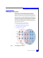
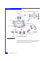
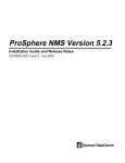
Figure 1 provides a view of the traditional LAN and SAN but now
using Fiber Channel over Ethernet (FCoE) technology to bridge the
gap in the I/O consolidation area. FCoE provides I/O consolidation
over Ethernet, allowing Fibre Channel and Ethernet networks to
share a single, integrated infrastructure, thereby reducing network
complexities in the data center.
This section briefly discusses the following:
Figure 1
◆
“Local Area Network (LAN)” on page 16
◆
“Storage Area Network (SAN)” on page 16
◆
“Converged network” on page 17
◆
“Virtualization” on page 18
FCoE, Bridging the LAN and SAN
Defining your environment
15
Introduction to Managing Data Center Connectivity
Local Area Network (LAN)
The left side of Figure 1 on page 15 shows a typical layout of a LAN
environment. This area is where you find core routers and switches,
working their way out to the edge switches and down to host
connectivity. Traditionally you would use tools like EMC Ionix™ IT
Operations, which monitors all your connectivity components and
provides you with root cause analysis if something should fail.
There are other tools that could provide some high-level network
monitoring, but were designed more for system and data center
environment monitoring.
Storage Area Network (SAN)
The right side of Figure 1 displays a more traditional SAN
environment. This area is typically managed by storage
administrators and consists largely of hosts connected to storage
arrays through Fibre Channel switches.
Administrators wanted a tool that would allow them to make
connections from their hosts to their storage and to be able to monitor
the flow of data from one end of the connection through the switch to
the storage. Tools existed to perform these functions.
One such tool is EMC Ionix ControlCenter,® which not only manages
switches, but provides a wide array of other tools, like array
management, host management, and reporting capabilities. Older
management software from Brocade and Cisco tend to focus mostly
on the management of the switches.
16
SAN Management TechBook
Introduction to Managing Data Center Connectivity
Converged network
iSCSI and FCoE are two ways of sending Fibre Channel protocol over
Ethernet. FCoE, which blends Fibre Channel and Ethernet (typically
managed separately). This document focuses on FCoE, part of a new
technology known as I/O convergence, and the new software tools to
manage this environment. FCoE bridges the gap in the I/O
consolidation area.
Like many new technologies, there were questions about whether
FCoE would replace the need for the traditional SAN environments.
However, SANs are still part of the data center and there is no sign of
them disappearing in the near future. What FCoE allows is a true
blending of technologies. Fibre Channel packets are now being mixed
in an Ethernet world.
Protocol convergence, such as FCoE, acts as a bridge for LAN and
SAN traffic. Figure 1 on page 15 shows FCoE overlapping the
traditional LAN and SAN areas. As a result there is also an overlap of
management responsibilities.
For detailed information about FCoE, refer to the Fibre Channel over
Ethernet (FCoE) Data Center Bridging (DCB) Concepts and Protocols
TechBook available in the E-Lab Navigator, Topology Resource
Center tab at http://elabnavigator.EMC.com. Also available is an
FCoE TechBook that provides case studies to further understand and
use this new technology, Fibre Channel over Ethernet (FCoE) Data
Center Bridging (DCB) Case Studies TechBook.
It is important to know what types of software management is
available to support this new technology. “Software management
tools” on page 20 lists three of these new tools, which will be further
discussed this document:
◆
Connectrix Manager Converged Network Edition (CMCNE),
◆
Brocade Network Advisor (BNA)
◆
Cisco Data Center Network Manager (CDCNM)
Defining your environment
17
Introduction to Managing Data Center Connectivity
Virtualization
With the advent of virtualization and unified networking, the
complexity of managing data center infrastructure has greatly
increased. New tools are being developed to work in this new virtual
environment.
Virtualization lets you run multiple virtual machines on a single
physical machine, with each virtual machine sharing the resources of
that one physical computer across multiple environments. Different
virtual machines can run different operating systems and multiple
applications on the same physical computer.
The traditional, inflexible, and hierarchical model of separately
provisioned and maintained server, storage, and network resources
constrains organizations from cost-effectively providing on-demand
support for applications and meeting unprecedented service levels.
The efficiency and availability of IT resources and applications can be
improved through virtualization. You can eliminate the old “one
server, one application” model and run multiple virtual machines on
each physical machine.
This direction allows IT administrators to spend more time on
innovation rather than managing servers. Too often approximately
70% of a typical IT budget in a non-virtualized data center goes
toward maintaining the existing infrastructure.
Virtual networking uses data center physical networking features,
standards, and principles to complement and extend existing data
center networks to the virtual machine level of granularity and
control.
Various components of a virtual network include virtual Ethernet
adapters, virtual switches, and VLANs, that all work together to
make virtualization possible.
It is beyond the scope of this TechBook to provide more information
on virtualization and products such as VMware, VPLEX, Invista,
Ionix Server Manager, and other tools that can be used to manage a
virtual infrastructure.
18
SAN Management TechBook
Introduction to Managing Data Center Connectivity
Defining your requirements
When tasked with the responsibility of selecting which tools or
products your organization will need in order to manage the overall
connectivity in the data center, there are many questions to ask and
variables to weigh and consider. The following are only some things
to consider when choosing software management tools:
◆
Size of the data center
◆
Scalability
◆
Cost
◆
Resources
◆
Usability
◆
Customization
◆
Installation
◆
Time
◆
Performance
◆
Flexibility
◆
Simplicity
◆
Security
◆
Software requirements
◆
Hardware requirements
For some questions and answers about selecting the right software
management tool for managing your data center connectivity, refer to
Chapter 4, ”Choosing A Software Management Tool.”
Defining your requirements
19
Introduction to Managing Data Center Connectivity
Software management tools
The needs of the group in a particular data center often dictate the
type of software management tools required. Refer to “Defining your
requirements” on page 19 to identify some important features you
require from a management tool. New tools are being designed to
help manage the connectivity environment as a whole.
To address the need of managing converged, network data centers,
the following management tools are currently available and are the
focus of this document:
◆
Connectrix Manager Converged Network Edition (CMCNE)
Refer to “CMCNE and BNA,” “EMC Connectrix Manager
Converged Network Edition” on page 24.
◆
Brocade Network Advisor (BNA)
Refer to “CMCNE and BNA,” “Brocade Network Advisor” on
page 41.
◆
Cisco Data Center Network Manager (CDCNM)
Refer to “Cisco DCNM” on page 55.
EMC also has solutions that can manage both host and storage
environments and perform some basic monitoring and discovery of
the switch environment, which are beyond the scope of this
document, including:
◆
ProSphere. This new product is deployed as a VMware
application, so an ESX server would have to be present in order to
deploy the software. The intended purpose of this product is
more about storage management than it is about switch
management.
◆
EMC Ionix ControlCenter (in the event VMware is not present in
the data center). This product has been available for a long time
and is a good fit for many of the traditional SAN environments.
In addition to monitoring the SAN environments both of these
products provide solid array and host management capabilities.
More information can be found on these, and other, EMC products on
http://Powerlink.EMC.com.
20
SAN Management TechBook
Introduction to Managing Data Center Connectivity
Connectivity work can also be performed using command line
interface (CLI). CLI will always have its place, but in most cases
where the learning curve is much shorter and the speed at which one
can start managing a connectivity environment is much faster, a
software management tool is a better fit.
Overall, software management tools provides quicker and easier
ways to monitor, troubleshoot, and maintain environments. A good
software management package aids in the overall productivity in the
data center.
There are other possible solutions and certainly more products will
be released to meet the needs of rapidly evolving technologies, but it
is beyond the scope of this document to discuss them all.
Software management tools
21
Introduction to Managing Data Center Connectivity
22
SAN Management TechBook
2
CMCNE and BNA
EMC Connectrix Manager Converged Network Edition (CMCNE)
and Brocade Network Advisor (BNA) are closely aligned. Therefore,
much of the information contained in this chapter is applicable to both
tools. The main difference is that CMCNE has Call Home functionality
and BNA does not.
This chapter contains the following information:
◆
◆
◆
EMC Connectrix Manager Converged Network Edition.............. 24
Brocade Network Advisor ................................................................. 41
Using CMCNE and BNA to manage data center connectivity .... 47
CMCNE and BNA
23
CMCNE and BNA
EMC Connectrix Manager Converged Network Edition
EMC Connectrix Manager Converged Network Edition (CMCNE) is
a management application capable of managing both traditional SAN
environments as well as the newer converged ethernet technology,
Fibre Channel over Ethernet (FCoE). CMCNE can manage traditional
SAN switch technology, but also has the ability to work with FCoE
and IP. This section briefly discusses the following information:
◆
◆
◆
◆
◆
“Licensing” on page 25
“User interface” on page 26
“Components” on page 27
“New features” on page 33
“References” on page 40
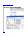
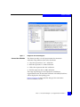
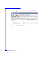
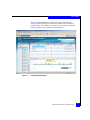
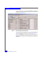
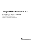
Figure 2 shows the main view of CMCNE, where users can complete
most fabric and switch configuration and perform fabric monitoring.
Figure 2
24
CMCNE View All
SAN Management TechBook
CMCNE and BNA
For more detailed information, refer to the EMC Connectrix Manager
Converged Network Edition Professional, Professional Plus, and Enterprise
User Guide, located on Powerlink.
Licensing
A license key is required to run the CMCNE application. The
following three versions of the application are available:
◆
Connectrix Manager Converged Network Edition - Enterprise
Edition
◆
Connectrix Manager Converged Network Edition - Professional
Plus Edition
◆
Connectrix Manager Converged Network Edition - Professional
Edition
The Enterprise Edition is the full-featured version for the
Director-class market.
The Professional Plus is designed for medium sized businesses or
departmental storage networks. Professional Plus is very similar in
functionality to the Enterprise version but limited in
features/scalability by a license key.
The Professional Edition has limited features and is targeted for the
small SAN switch market. The Professional Edition is included for
free with every switch product sold.
The key specifies the expiration date of a trial license, as well as the
number of ports allowed. If you selected 75 days trial during
installation, you can use the application, including all of its features,
for a trial period of 75 days. At the termination of the trial period, a
License expired confirmation message displays. You must enter a
license key to continue using the application. There are options to
have IP license only or SAN + IP license.
For more information on CMCNE or licensing, refer to
http://www.powerlink.emc.com or contact your EMC CMCNE
account representative.
EMC Connectrix Manager Converged Network Edition
25
CMCNE and BNA
User interface
The management application provides easy, centralized management
of the SAN, as well as quick access to all product configuration
applications. Using this application, you can easily configure,
manage, and monitor your networks.
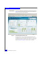
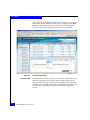
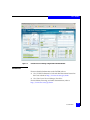
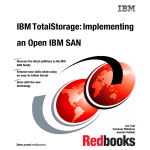
Figure 3 shows the user interface main window. The IP tab is new
and now allows for the discovery, monitoring, and managing of IP
devices, in addition to traditional SAN and FCoE switches.
The management application’s main window contains a number of
areas. Some panels may be hidden by default. To view all panels,
select View > Show Panels > All Panels, or press F12.
Figure 3
26
CMCNE Main window
SAN Management TechBook
CMCNE and BNA
Components
Basic information on the following CMCNE components is included
in this section:
Discovery
◆
“Discovery” on page 27
◆
“Zoning” on page 28
◆
“Alerting” on page 30
◆
“Monitoring” on page 31
Discovery is the process by which the management application
contacts the devices in your environment. Discovery interfaces with
the switches in a fabric, or multiple fabrics, and loads information
about those switches into a resident database. Among other things,
the information includes hardware type, firmware versions, and port
information.
Once a discovery is completed, a user has the ability to display a
topology view that provides a layout of the overall fabric as it has
been discovered. For more detailed information or step-by-step
procedures on how to discover a switch or fabric, refer to the
appropriate user guide.
Similar to Brocade Network Advisor (BNA), discussed further in
“Brocade Network Advisor” on page 41, CMCNE discovers devices
through a seed switch and is capable of handling multiple fabrics
within one topology view. For firmware and switch model
requirements of a seed switch, refer to the EMC Connectrix Manager
Converged Network Edition Professional, Professional Plus, and Enterprise
User Guide, located on Powerlink.
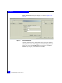
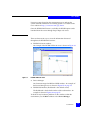
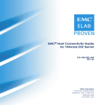
Figure 4 on page 28 shows the CMCNE Discovered Fabrics dialog
box. You click Add to specify the IP addresses of the devices you
want to discover.
EMC Connectrix Manager Converged Network Edition
27
CMCNE and BNA
The Add Fabric Discovery dialog box displays, also shown in
Figure 4.
Figure 4
CMCNE Discover Fabrics and Add Fabric Discovery dialog box
You fill in the blanks and then select OK for the discovery process to
begin.
Zoning
Zoning defines the communication paths in a fabric. Zoning enables a
set of devices connected to a switched Fibre Channel fabric, or a Fibre
Channel over Ethernet (FCoE) fabric, to communicate with each
other; for example, a host and a storage array.
Each zone groups the end ports of the devices involved or the switch
ports physically connected to those end ports. Using multiple zones,
a single host can communicate with multiple storage devices, and
vice versa.
A zone set is a collection of zones that can be activated together,
partitioning a fabric into zones. Only one of the zone sets associated
with a fabric can be active at any time. It is this active zone set that
determines which of the devices connected to the fabric can
communicate with each other.
28
SAN Management TechBook
CMCNE and BNA
Zoning information is retained in a zoning library, which can be
maintained at a switch level or in a database within the connectivity
tool being used.
CMCNE can configure zoning both online and offline.
◆
Online zoning directly modifies the fabric zone database that
resides on each individual switch.
◆
Offline zoning modifies the zone library that is stored in the
CMCNE resident database.
Aliases are used in CMCNE zoning system to associate with a group
of port index numbers and WWNs. This makes zone configuration
easier by enabling you to configure zones using an alias rather than
by inputting a long string of individual members.
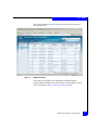
Zoning by WWN, Domain/Port Index, or alias is supported. The
CMCNE zoning configuration Compare function can be found in the
Zone DB Operation drop-down menu in the upper right-hand
corner of the Zoning configuration window, as shown in Figure 5. It
highlights the differences between two selected databases and
merges them under users' permission and preferences.
Figure 5
CMCNE Zoning dialog box, Zone DB Operation drop-down men
EMC Connectrix Manager Converged Network Edition
29
CMCNE and BNA
Multiple zone configurations can be present within CMCNE. An
active zone set is indicated by a green label in front of the zone set
name, as shown in Figure 5.
Alerting
Problem notification is an integral part of any connectivity tool.
Administrators need to know immediately when there are problems
or issues within their environments. Notification is one component of
alerting, but the ability to set thresholds for performance issues is also
important.
The main view from CMCNE shows current alerts and updates and
refreshes with any new alerts. You can choose to generate emails or
notifications when alerts occur.
To drill down to a reported problem, in the SAN tab select a switch
that has an alert, right-click the switch, and select Events from the
Monitor tab drop-down menu.
When an alert occurs, you can drill down to the offending component
to get more details as well as examine log files to determine root
causes. Under the Monitor tab drop-down menu, you have the
ability to set up SNMP so traps generated by an alert can be sent to an
Enterprise tool and monitoring tools that can translate the trap. As
30
SAN Management TechBook
CMCNE and BNA
shown in Figure 6, there are many options from the Monitor tab
drop-down menu.
Figure 6
Monitoring
Monitoring alerts
It is essential to be able to monitor your environment. The ability to
take a quick glance at your environment and see potential problems,
or be aware of breakdowns as they happen, is a key element in any
connectivity tool. Almost all tools today have the ability to display a
main view allowing for a quick check of your environment. Some
tools allow various modifications to tailor your environment.
Monitoring is not limited to just alerts or status. It should also
provide an ability to follow the performance of your fabric. The
following performance monitoring tools are briefly discussed:
◆
“Real-time performance graph” on page 32
◆
“Historical performance graph” on page 33
Both the real-time and historical graph can be opened from the
Monitor tab drop-down list in CMCNE main view.
EMC Connectrix Manager Converged Network Edition
31
CMCNE and BNA
Real-time performance graph
CMCNE performance monitoring provides details about how much
traffic and errors a specific port or switch generates on the fabric over
a specific timeframe. You can monitor a switch's real-time
performance through a performance graph that displays transmitted
and received data, as shown in Figure 7.
Figure 7
32
Real time performance graph
SAN Management TechBook
CMCNE and BNA
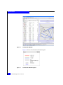
Historical performance graph
You can also refer to the historical performance chart or report to get
an idea of port performance over time, as shown in Figure 8.
Figure 8
Historical performance graph
New features
This section discusses some new features in CMCNE, including:
Top Talker monitoring
◆
“Top Talker monitoring” on page 33
◆
“Virtual Fabrics” on page 35
◆
“Diagnostic Port (D_Port)” on page 36
◆
“Connection utilization” on page 37
◆
“Performance analysis” on page 39
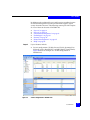
Top Talker monitoring allows SAN administrators to find out more
about the port utilization of the devices. It displays the connections
using the most bandwidth on a selected device or port.
The Top Talker feature and Fibre Channel routing can be used
concurrently for FOS firmware v7.x and later.
EMC Connectrix Manager Converged Network Edition
33
CMCNE and BNA
Note: This feature requires the Brocade Advanced Performance Monitoring
license and switches running on FOS 6.2 and later.
For FOS 6.x, this feature cannot be used when Fibre Channel routing is
turned on for the switches.
Note the following:
◆
Up to 10 switches can be monitored for the fabric mode Top
Talkers.
◆
Up to 32 ports (24 - 8 Gb/s FC port, 8 - 10 Gb/s port) can be
monitored for the F_Port Top Talkers.
◆
Top Talkers is only supported on the 8 Gb/s (and higher) FC
ports.
◆
By default, the top five busiest ports are listed in the Top Talker
dialog. You can choose to view the top 1 to 20 in a a drop-down
dialog box.
◆
The Top Talker summary table displays all Top Talkers that
occurred since the dialog box was opened, up to a maximum of
360 records. Details such as Rx/Tx average, occurrences, source,
source switch/port, destination, destination switch/port, percent
utilization, last occurred, SID, source port, DID, destination port,
and port speed can be viewed in the summary table.
The CMCNE Top Talkers dialog box, shown in Figure 9 on page 35,
displays the Current Top Talkers and Top Talker Summary for a
selected switch (Fabric Mode) or F_Port.
34
SAN Management TechBook
CMCNE and BNA
Figure 9
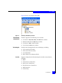
Virtual Fabrics
CMCNE Top Taler dialog box
Virtual Fabrics allows SAN administrators to view the entire SAN,
both physical and logical, at a glance. It easily determines the logical
switches with the icon (V) and provides logical isolation of data,
control, and management paths at the port level.
The Virtual Fabrics feature divides a physical chassis into multiple
logical switches. Logical switches can consist of one or more ports
and act like a single Fibre Channel switch. Logical switches can be
interconnected to create a logical fabric.
The following are some of the benefits of using CMCNE to manage
Virtual Fabrics.
◆
Ability to manage a logical switch the same as a physical switch.
◆
Ability to use a logical switch for discovery and eliminate the
requirement for one physical chassis for one fabric.
EMC Connectrix Manager Converged Network Edition
35
CMCNE and BNA
◆
Ability to manage multiple Virtual Fabrics-capable physical
chassis from the same interface.
Figure 10 shows the Logical Switches dialog box.
Figure 10
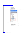
Diagnostic Port
(D_Port)
Logical Switches dialog box
This feature is used to diagnose optics (16 G SFP+) and cables for the
Condor 3 platform. It can be used to perform functional or stress
testing. The following lists testing that can be performed:
◆
Electrical loopback test
◆
Optical loopback test
◆
Link distance test
◆
Link saturation test
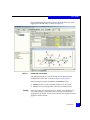
Figure 11 on page 37 shows the how to use the Diagnostic Port Test
dialog box to select an existing fabric as a template or to create a new
template.
36
SAN Management TechBook
CMCNE and BNA
Figure 11
Connection utilization
Diagnostic Port test dialog box
This feature provides a visual representation for connection
utilization using different color codes. By default:
◆
Grey line represents 0% to 1% utilization
◆
Blue line represents 1% to 40% utilization
◆
Yellow line represents 40%-80% utilization
◆
Red line represents 80% to 100% utilization.
The range of percentages can be adjusted to suit different
organizational needs. If connection utilization is disabled, black lines
will be displayed in the topology pane.
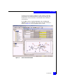
Figure 12 on page 38 shows the blue and grey line connections
between different switches.
EMC Connectrix Manager Converged Network Edition
37
CMCNE and BNA
Figure 12
Connection utilization
Figure 13 shows the connection utilization legend.
Figure 13
38
Connection utilization legend
SAN Management TechBook
CMCNE and BNA
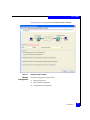
Performance analysis
This feature collects data from managed switches in the SAN. It
currently supports only the FC ports (E_Ports and F_Ports), GE ports,
and FCIP tunnels. The polling rate can be adjusted from 10 seconds
up to 1 minute. Up to 32 ports and 10 devices can be selected for
graphing performance.
In addition to real-time performance graphs, CMCNE can also
provide historical graph (as shown in Figure 8 on page 33) and
report, and perform an initiator-to-target monitor (end-to-end
monitor).
Figure 14 shows an example of the Real Time Performance Graphs
dialog box.
Figure 14
Real time performance graphs dialog
EMC Connectrix Manager Converged Network Edition
39
CMCNE and BNA
References
For more detailed information, refer to the EMC Connectrix Manager
Converged Network Edition Professional, Professional Plus, and Enterprise
User Guide, located on Powerlink.
40
SAN Management TechBook
CMCNE and BNA
Brocade Network Advisor
Brocade and EMC have a long-standing partnership to provide
customers with innovative solutions in an ever-changing and
challenging environment.
Brocade Network Advisor (BNA) is a unified network management
solution designed to simplify and automate network operations by
unifying network management of SAN, IP (including Ethernet
fabric), and wireless environments. Again, CMCNE and BNA are
closely aligned. This section briefly describes the following:
◆
“Licensing” on page 41
◆
“BNA Dashboard” on page 41
◆
“Brocade VDX switches” on page 42
◆
“Brocade VCS Fabric technology” on page 43
◆
“Ethernet fabrics” on page 44
◆
“References” on page 46
Licensing
Licensing information for Brocade products can be found in the
"Licenses" section available on http://www.brocade.com, or contact
your Brocade BNA account representative.
BNA Dashboard
Brocade Network Advisor (BNA) supports Fibre Channel SANs,
FCoE, IP switching and routing (including Ethernet fabrics), and
MPLS networks, providing end-to-end visibility across different
network types through a seamless and unified user experience.
BNA supports the following networks:
◆
◆
◆
◆
◆
◆
Fibre Channel Storage Area Network (SANs),
Fibre Channel over Ethernet (FCoE)
Layer 2/3 IP networks (including those running Brocade VCS
technology)
Wireless networks
Application delivery
Multiprotocol Label Switching (MPLES)
Brocade Network Advisor
41
CMCNE and BNA
Brocade Network Advisor can manage thousands of devices across
different types of environments. BNA provides a unified dashboard
view of storage and IP networks, as shown in Figure 15 on page 42.
Visibility of the SAN and IP tab is controlled by the active licensing
option (see “Licensing,” discussed next), which determines if the
product displays all three tabs, the Dashboard and SAN tabs only, or
the Dashboard and IP tabs only. The IP tab is new and now allows
for the discovery, monitoring, and managing of IP devices, in
addition to traditional SAN and FCoE switches.
Figure 15
Brocade Network Advisor Dashboard
Brocade VDX switches
The Brocade VDX data center switch family enables IT organizations
to build Ethernet fabrics that support cloud-optimized networking
42
SAN Management TechBook
CMCNE and BNA
and greater enterprise agility. These switches simplify network
architecture, increase scalability, and increase network performance
and resiliency with Ethernet fabrics in virtualized data centers.
VDX switches support comprehensive Layer 2 LAN capabilities and
protocols, including Link Aggregation Control Protocol (LACP) and
802.1Q.
Brocade VCS Fabric technology
Brocade VCS Fabric technology enables organizations to build
high-performance cloud-optimized data centers while preserving
existing network designs and cabling, and gaining active-active
server connections. For scale-out fabric architectures, Brocade VCS
Fabric technology allows organizations to flatten network designs,
provide Virtual Machine (VM) mobility without network
reconfiguration, and manage the entire fabric more efficiently.
Brocade VCS Fabric technology offers features to support virtualized
server and storage environments. It simplifies network architectures
and enables cloud computing by enabling organizations to build data
center Ethernet fabrics.
VCS Fabric technology is embedded in the Brocade FDX data center
switch family.
Brocade Network Advisor
43
CMCNE and BNA
Figure 16 shows an example of the Brocade VCS Fabric technology.
Figure 16
Brocade VCS Fabric technology
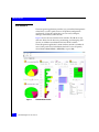
Ethernet fabrics
An Ethernet fabric provides higher levels of performance, utilization,
availability, and simplicity than the classic hierarchical Ethernet
architectures. It eliminates the need for STP.
44
SAN Management TechBook
CMCNE and BNA
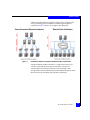
Unlike hierarchical Ethernet, Ethernet fabrics allows all paths to be
active, providing greater scalability and reducing management
complexity. Figure 17 shows an example of the differences.
Figure 17
Hierarchical Ethernet compared to Ethernet Fabric architecture
Advanced Ethernet fabrics function as a single logical entity. All
switches automatically know about each other as well as all
connected physical and logical devices. The advantage is that
management can then be domain-based and defined by policy rather
than device-based and defined by repetitive procedures.
Brocade Network Advisor
45
CMCNE and BNA
References
Further information on the Brocade technologies discussed in this
section can be found in the Brocade Network Advisor IP User Manual,
available on the Brocade website, http://www.brocade.com,
MyBrocade, Brocade Network Advisor documentation.
Subjects in this manual include:
◆
Fiber Channel over Ethernet
◆
Security Management section
• MAC and Layer 3 Access Control lists
◆
SSL Certificate Manager for Application Products
◆
Virtual IP (VIP) Server Manager
◆
Global Server Load Balancing (GSLB)
◆
MPLS Manager (Multiprotocol Label Switching)
The following data sheets on the Brocade website are also useful:
46
◆
Brocade Network Advisor Data Sheet
◆
Brocade VDX 6720 Data Center Switch Data Sheet
SAN Management TechBook
CMCNE and BNA
Using CMCNE and BNA to manage data center connectivity
This section briefly describes the benefits of CMCNE and BNA to
manage your data center connectivity. These tools are closely related
so much of the information in this section is applicable to both. The
only difference is that CMCNE has Call Home functionality.
This section further discusses these tools and how they relate to the
following:
◆
“Network management” on page 47
◆
“IP features” on page 52
CMCNE and BNA provide an easy, user-friendly centralized data
center management. They give quick access to all product
configuration applications. Using these intuitive applications, you
can configure, manage, and monitor your networks with ease.
Network management
The most important aspect of data center network management is the
technology that supports most, if not all, of the activities associated
with running a data center infrastructure. CMCNE and BNA are
unified network management systems for managing converged data
network and storage network. CMCNE and BNA support intuitive
and intelligent features that an administrator needs in maintaining,
monitoring, and managing data center network components. They
provide comprehensive operations support within a single
framework.
CMCNE and BNA also support unified networking (through FCoE,
10 Gb/s Ethernet and SAN) and have virtualization awareness
(through association between port profiles) and VMware port groups
(through integration with VMware vCenter).
Administrators can use the easy-to-use Device Configuration wizard
to configure and manage network devices.
Additionally, the integrated Change Manager allows administrators
to:
◆
Track device configuration changes
◆
Enable viewing
◆
Retrieve files
Using CMCNE and BNA to manage data center connectivity
47
CMCNE and BNA
◆
Restore configuration files
◆
Monitor configuration change for troubleshooting purposes
One important new feature of CMCNE and BNA network
management software is the Brocade Virtual Cluster Switching (VCS)
fabric management. This new Ethernet technology removes many
limitations of classic Ethernet networks in the data center.
In addition to Layer 2 switching and Layer 3 routing, CMCNE and
BNA also support Metro and Carrier Ethernet networks. It provides
comprehensive management of MPLS services through the MPLS
Manager and supports MPLS Virtual Private LAN Services (VPLS),
Label Switched Path (LSP), Local VPLS, Virtual Leased Line (VLL),
and Local VLL services with an intuitive interface.
The following are some examples of main features of using CMCNE
or BNA in a data center, including some example screenshots.
◆
Layer 2 switching
• VLANs, DCB, Spanning Tree Protocols such as 802.1D and
Rapid STP, PortChannels, 802.1ag, Power over Ethernet (PoE).
Figure 18 on page 49 shows an example of a DCB
configuration, where most of the L2 options can be
configured.
48
SAN Management TechBook
CMCNE and BNA
Figure 18
DCB configuration
◆
Layer 3 routing
• Layer 3 Mobility, Virtual IP (VIP), Global Server Load
Balancing (GSLB).
◆
Support for Fiber Channel over Ethernet (FCoE), wireless
networks, application delivery networks, and Multiprotocol
Label Switching (MPLS) networks in service provider
environments.
◆
Security, including
• RBAC, AAA, MAC Access Control lists, Layer 3 Access
Control lists, 802.1x, SSL Certificate Manager.
Using CMCNE and BNA to manage data center connectivity
49
CMCNE and BNA
Figure 19 shows an example of how an 802.1x configuration
can be accessed from a DCB configuration.
Figure 19
Enable 802.1x configuration
◆
Comprehensive management, including
• Configuration, monitoring, and management of Brocade VDX
switches, the Brocade DCX Backbone family, Brocade routers,
Brocade Ethernet switches, Brocade Host Bus Adapters
(HBAs), and Converged Network Adapters (CNAs).
◆
Easy-to-use Deployment Manger and Device Configuration
wizard to configure and manage devices.
Figure 20 on page 51 shows an example of the Configuration
dialog box.
50
SAN Management TechBook
CMCNE and BNA
Figure 20
Configuration dialog box
◆
Network device configuration tracking and retrieval through
Change Manager.
◆
Real-time and historical performance monitoring, traffic analysis,
change management, and policy-driven remedial actions.
Figure 7 on page 32 provides an example of a real-time
performance graph. Figure 8 on page 33 provides an example of
an historic performance graph. Figure 21 on page 52 shows an
example of a traffic analyzer.
Using CMCNE and BNA to manage data center connectivity
51
CMCNE and BNA
Figure 21
Brocade Network Advisor Traffic analyzer
◆
Troubleshooting tools through proactive alerts with real-time
logging, diagnostic, and fault isolation capabilities.
◆
Simplified data center automation through advanced Brocade
VCS fabric management, an Ethernet fabric technology available
in the Brocade VDX switch family.
◆
VM awareness through association of profiles to Virtual Machines
(VMs).
◆
Intuitive features, including
• CLI Manager, IP Element Manager, Image Repository for IP
products, Packet Capture (Pcap), Frame Monitor.
IP features
With the advent of virtualization and unified networking, the
complexity of managing data center infrastructure has greatly
increased. The intricacy of data networking and the dramatic growth
of different IP services such as the world-wide web, email, online
52
SAN Management TechBook
CMCNE and BNA
shopping, video conferences, and multicast applications (such as
music streaming), depend on reliable wired and wireless networks.
To address this need, a new IP tab was developed for the CMCNE
and BNA. The IP protocol can be used not only in LAN, but also in IP
SAN and converged networking.
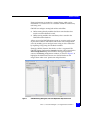
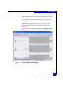
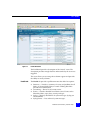
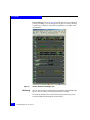
Figure 22 shows the information contained in the IP tab, including
the Product List, Topology Map, Master Log, and Minimap.
Figure 22
IP features under the IP tab
CMCNE and BNA support FCoE, Layer 2 switching, Layer 3 IP
networks (including those running Brocade VCS technology),
wireless networks, application delivery networks, and Multiprotocol
Label Switching (MPLS) networks in service provider environments.
Using CMCNE and BNA to manage data center connectivity
53
CMCNE and BNA
Figure 23 shows what features are accessible using the CMCNE IP
tab.
Figure 23
54
CMCNE IP accessible features
SAN Management TechBook
3
Cisco DCNM
Cisco Data Center Network Manager (DCNM) can manage storage
and data networking over the converged, virtualized data center.
This chapter provides basic information on the Cisco DCNM product
and how it works in the IP, SAN, and LAN environments.
◆
◆
◆
◆
DCNM .................................................................................................
Web-based interface (Dashboard)....................................................
DCNM-SAN........................................................................................
DCNM-LAN .......................................................................................
Cisco DCNM
56
59
66
78
55
Cisco DCNM
DCNM
Data center network management involves numerous complex
functions. From monitoring and maintaining the network devices to
provisioning the services, from data center network infrastructure
troubleshooting to capacity planning, from detecting security threats
to assessing the impact of scheduled network maintenance or
migration.
To address the need of managing converged, virtualized data centers,
Cisco merged two management solutions, Cisco Fabric Manager and
Cisco Data Center Network Manager for LAN, into one product, the
Cisco Data Center Network Manager (DCNM).
The DCNM has two main components:
◆
DCNM-SAN to manage storage fabrics, discussed further in
“DCNM-SAN” on page 66
◆
DCNM-LAN to manage data networks, discussed further in
“DCNM-LAN” on page 78
Administrators can still maintain control and segmentation through
role-based access control (RBAC) but now with easier visibility across
the network and storage access infrastructure.
DCNM simplifies management of the virtual infrastructure by
enabling management of the entire path through the physical to the
virtual network across the entire data center environment through a
single management dashboard.
This section provides the following basic information for the Cisco
Data Center Network Manager (DCNM).
◆
“Licensing” on page 57
◆
“Views” on page 57
More detailed information on DCNM can be found at the Cisco
website at http://www.cisco.com.
56
SAN Management TechBook
Cisco DCNM
Licensing
Different features for managing the SAN and LAN infrastructure are
available depending on licensing options. You can license the SAN
and LAN environments separately or together.
The following types of licensing for DCNM for SAN and DCNM for
LAN are available:
SAN
◆
Essentials Edition
• Cisco DCNM for SAN Essentials Edition is included with
Cisco MDS 9000 Family hardware.
◆
Advanced Edition
• Cisco DCNM for SAN Advanced Edition adds capabilities
such as performance monitoring and trending, virtual
machine–aware path analysis, event forwarding, and
federation across multiple data centers.
LAN
◆
Essentials Edition
• Cisco DCNM for LAN Essentials Edition is included with
Cisco Nexus Family hardware.
◆
Advanced Edition
• Cisco DCNM for LAN Advanced Edition adds capabilities
such as configuration management, image management,
virtual device contexts (VDCs), and Cisco FabricPath.
Licenses are now hosted on the management server and not the
switch. Detailed information on licensing options is available on the
Cisco website at http://www.cisco.com/go/dcnm.
Views
Cisco DCNM is a Java-based client-server application that allows the
client to be run remotely. Server and client components can be
deployed over various hardware and OS platforms. A browser-based
interactive dashboard to simplify the management of the virtual
infrastructure is also available.
DCNM
57
Cisco DCNM
There are three main ways to view the information discussed further
throughout this chapter:
◆
DCNM-SAN or DCNM-LAN main window
• An example of the DCNM-SAN main view is shown in
Figure 32 on page 71.
• An example of the DCNM-LAN main window is shown in
Figure 40 on page 81.
◆
Device Manager (for DCNM-SAN)
An element manager for MDS and N5K switches. An example of
the Device Manager view is shown in Figure 35 on page 74.
◆
DCNM Web interface (Dashboard is the default screen)
The Dashboard is the default window of the web interface. An
example is shown in Figure 36 on page 75.
More information is provided in “Web-based interface
(Dashboard)” on page 59.
To check for any hardware problems on the switches within the
environment, use the Main window or the Device Manager.
To check the overall health of the monitored environments, use the
web interface (Dashboard).
58
SAN Management TechBook
Cisco DCNM
Web-based interface (Dashboard)
The DCNM main window and Device Manager are used to manage
the SAN and LAN. These are similar to Fabric Manager. However, to
simplify the management of the virtual infrastructure, DCNM
provides a new, easy-to-use web interface, which this section will
briefly discuss. This window is sometimes referred to as the
Dashboard since that is the default window.
You can view all the dependencies from the virtual machine out to
the physical host, through the fabric, and to the storage array using
the virtual machine-aware (VM-aware) topology view. This view
allows easy access to a detailed view of the path attributes.
All the information needed to manage the virtual environment
including performance charts, inventory information, events, and
virtual machine and VMware ESX utilization information, is
displayed. Cisco DCNM maps paths from the server to storage,
enabling you to track mission-critical workloads across the entire
network.
The tabs of this interface are briefly described in the following
sections:
◆
“Dashboard tab” on page 60
◆
“Health tab” on page 61
◆
“Performance tab” on page 62
◆
“Inventory tab” on page 64
Web-based interface (Dashboard)
59
Cisco DCNM
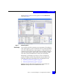
Dashboard tab
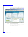
Figure 24
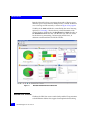
Reporting and drill-down capabilities have been greatly improved.
Figure 24 show the default view, the Dashboard, when logging into
the client web interface of DCNM-SAN.
DCNM-SAN Dashboard summary view
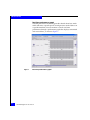
If multiple fabrics are discovered within the DCNM-SAN server
environment, you can select which specific fabric you want to view
and drill down further to specific events, switches, or performance
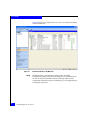
metrics. In Figure 25 on page 61 "critical" events" is selected.
60
SAN Management TechBook
Cisco DCNM
Figure 25
Event drill down
The Dashboard provides a description of the "critical" event. The
description provides enough detail to understand why the event was
triggered.
This view allows you to arrange how columns appear and provides
the ability to sort by columns.
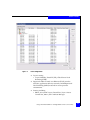
Health tab
The Health tab provides a pull-down menu that offers five options:
◆
◆
◆
◆
◆
Summary — Provides a summary of events and problems for all
SANs, or selected SAN, fabric, or switch. Clicking blue links
provides more information.
Accounting — Shows list of account events.
Events — Provides detailed list of fabric events. Events can be
filtered by fabric, scope, date, severity, and type.
Syslog — Displays detailed list of system messages. Syslog can
also be filtered.
Syslog Events — Lists archived system messages.
Web-based interface (Dashboard)
61
Cisco DCNM
Performance tab
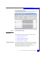
Figure 26
The Performance tab displays the overall performance within the
environment in the last twenty-four hour period. In addition to the
quick view provided, you have the ability to use a mouse fly-over to
better view a breakdown, such as a timeline, as shown in Figure 26.
Using mouse-over in Performance view
From the Performance pull-down menu you can select switch, ISL,
NPV Links, Ethernet, End Devices, Flows, and Other performance
statistics. For example, if you select a switch, you have three more
options: CPU, Memory, and Bandwidth.
62
SAN Management TechBook
Cisco DCNM
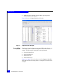
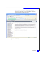
In Figure 27, Switch CPU is selected. The display initially gives
values, but there is an option to chart the numbers over a selected
period of time. This would prove useful if you are trying to correlate
peak usage times with overall switch performance.
Figure 27
Switch CPU performance
Web-based interface (Dashboard)
63
Cisco DCNM
You are able to select different end devices allowing you to correlate
information during different periods of time. In Figure 28, the Host
Ports are selected. Notice there is an option to select the period of
time you want to chart. It also allows you to select "real-time".
Figure 28
Inventory tab
64
Host Port performance
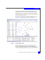
DCNM-SAN can collect many types of inventory information. It can
display the inventory of switches within a selected fabric, license
keys activated on any given switch, or a breakdown of the different
modules in every switch, along with serial numbers. This allows you
to audit what is currently in any given environment or physical
switch.
SAN Management TechBook
Cisco DCNM
The example shown in Figure 29 displays the module inventory of
the fabric selected.
Figure 29
Module inventory
Other tabs are available in this Dashboard, including Reports,
Backup, SME, and Admin. For more details on other options, refer to
the Cisco website at http://www.cisco.com/go/dcnm.
Web-based interface (Dashboard)
65
Cisco DCNM
DCNM-SAN
Although there is a new web interface with several new features,
many of the SAN or connectivity functions look and work like the
original Cisco Fabric Manager product. This section discusses the
following information and introduces the new web interface:
◆
“Licensing” on page 66
◆
“Views” on page 68
◆
“Benefits” on page 68
◆
“Components” on page 69
◆
“Features” on page 69
◆
“References” on page 77
DCNM-SAN is installed via a CD-ROM, unlike Fabric Manager that
was downloaded from a switch. Installation information can be
found on the Cisco website at http://www.cisco.com/go/dcnm.
Licensing
Refer to “Licensing” on page 57 for more detailed information on
licensing options.
The following types of licensing for DCNM for SAN are available:
SAN
◆
Essentials Edition
• Cisco DCNM for SAN Essentials Edition is included with
Cisco MDS 9000 Family hardware.
◆
Advanced Edition
• Cisco DCNM for SAN Advanced Edition adds capabilities
such as performance monitoring and trending, virtual
machine–aware path analysis, event forwarding, and
federation across multiple data centers.
• Cisco DCNM for LAN Advanced Edition adds capabilities
such as configuration management, image management,
virtual device contexts (VDCs), and Cisco FabricPath.
Licenses are now hosted on the management server and not the
switch. Detailed information on licensing options is available on the
Cisco website at http://www.cisco.com/go/dcnm.
66
SAN Management TechBook
Cisco DCNM
Once the DCNM-SAN license is available, the DCNM option can be
launched from the server through http or https web access.
Figure 30 shows the DCNM-SAN option from the DCNM main page.
Figure 30
DCNM-SAN option in Data Center Network Manager
For more information on DCNM-LAN installation, refer to the Cisco
DCNM Installation and Licensing Guide available on the Cisco website
at http://www.cisco.com/go/dcnm.
For more information about the Cisco DCNM software or other
licensing information, contact your Cisco account representative.
DCNM-SAN
67
Cisco DCNM
Views
There are three main ways to view the information discussed
throughout the DCNM-SAN sections:
◆
DCNM-SAN main window
An example of the DCNM-SAN main view is shown in Figure 32
on page 71.
◆
Device Manager (for DCNM-SAN)
An element manager for MDS and N5K switches. An example of
the Device Manager view is shown in Figure 35 on page 74.
◆
DCNM Web interface (Dashboard is the default screen)
The Dashboard is the default window of the web interface. An
example is shown in Figure 36 on page 75.
To check for any hardware problems on the switches within the
environment, use the Main window or the Device Manager.
To check the overall health of the monitored environments, use the
web interface (Dashboard).
Benefits
Cisco DCNM simplifies management of the data center, offering the
following benefits with the new web interface:
◆
Virtual Machine-aware path management
Enables management of the entire path through the physical to
the virtual network across the entire data center environment
using VMpath (identifies bottlenecks) and VM-aware (shows
dependencies) views.
◆
Performance and troubleshooting
Monitors and provides alerts for fabric availability and
performance.
◆
Interactive dashboard
Provides capability to view more details of key performance
indicators (KPIs). Proactively measures, analyzes, and predicts
performance of SAN infrastructure.
68
SAN Management TechBook
Cisco DCNM
◆
Scalability
Uses federation to scale to large and distributed data center
deployments.
For more information, refer to “Web-based interface (Dashboard)” on
page 59.
Components
DCNM-SAN uses interdependent software components that
communicate with the switches. Components include:
◆
DCNM-SAN Server
◆
DCNM-SAN Client
◆
Device Manager
◆
DCNM-SAN Web Client
◆
Performance Manager
◆
Cisco Traffic Analyzer
◆
Network Monitoring
◆
Performance Monitoring
Detailed information on these components can be found in the Cisco
DCNM Fundamentals Guide and other documents located on the Cisco
website at http://www.cisco.com/go/dcnm.
Features
This section discusses some of the necessary features used to manage
a connectivity environment, including:
Discovery
◆
“Discovery” on page 69
◆
“Zoning” on page 71
◆
“Alerts” on page 72
◆
“Monitoring” on page 74
After installing the DCNM-SAN server components, one option
when logging into the server will be to discover a fabric. Enter the IP
address of the seed switch in the Fabric you wish to discover, provide
the necessary login credentials, and click Discover from the Control
DCNM-SAN
69
Cisco DCNM
Panel. The Discover dialog box displays, as shown in Figure 31 on
page 70.
Figure 31
Discover dialog box
After the initial discovery is performed, there is no need to perform
subsequent discoveries when logging in to DCNM. Simply select the
fabric you want in the DCNM-SAN main window in the Logical
Domains top-left pane, under SAN and click OK.
70
SAN Management TechBook
Cisco DCNM
The DCNM-SAN main window will now be the default view when
logging in to DCNM-SAN, as shown in Figure 32.
Figure 32
DCNM-SAN main window
Like Fabric Manager, you can still launch Device Manager from
DCNM-SAN's main view, as shown in Figure 33 on page 72.
Device Manager provides the Device and Summary View.
Zoning
◆
Summary view is used to monitor interfaces on the switch.
◆
Device view is used to perform switch-level configurations.
Zones and zone sets are based on Cisco VSANs. Each VSAN has its
own zoning database containing zones and zone set information
applicable to the VSAN. A zone or zoneset from one VSAN cannot be
applied to another VSAN.
DCNM-SAN
71
Cisco DCNM
Multiple zones and zonesets can reside within each VSAN created.
However, only one zoneset can be active at any given time. Figure 33
on page 72 shows an example of the Zoning view in a DCNM-SAN.
Figure 33
DCNM-SAN Zoning view
By highlighting a particular VSAN in the upper left-hand pane, the
corresponding VSAN components is highlighted in the map display.
Once you have selected a VSAN, simply select the Zone option from
the drop-down menu to begin your zoning configuration.
Alerts
72
Alerts can be monitored throughout the environment from either:
◆
Main window
◆
Device Manager
◆
Web interface
SAN Management TechBook
Cisco DCNM
To check for any hardware problems on the switches within the
environment, use the Main window or the Device Manager. The
Dashboard is used to check the overall health of the monitored
environments.
In the Main window, highlight Switches under the Physical
Attributes pane on the bottom right-hand side of the window, as
shown in Figure 34, to view attributes of the switch.
Figure 34
Alerts in the Main window
DCNM-SAN
73
Cisco DCNM
Device Manager, shown in Figure 35, drills down into an individual
switch, providing a view of the physical layout of a switch, allowing
a quick way to check for any hardware problems on switches in the
environment.
Figure 35
Monitoring
Alerts in the Device Manager view
You can monitor the overall health of your fabric using DCNM-SAN.
There is also an ability to monitor performance real-time.
To check the health of the environments being monitored, you can
invoke DCNM-SAN through the web interface.
74
SAN Management TechBook
Cisco DCNM
The default screen, or Dashboard, shown in Figures 36, shows a
breakdown of the environment selected and also allows the ability to
drill-down to specific issues found. You have the ability to switch
between environments if you are monitoring more than one.
Figure 36
Monitoring environment health using DCNM-SAN Dashboard
DCNM-SAN
75
Cisco DCNM
Using Device Manager, you can look at a Summary view, which lists
all of the modules in the switch and displays the overall performance
of each, as shown in Figure 37.
Figure 37
Device Manager performance monitor
You can also monitor the performance using the DCNM Dashboard
available through the web interface. As shown in Figure 38 on
page 77, the Dashboard view provides a quick look into some of the
performance components in the fabric being monitored. There is an
ability to drill down further for a more comprehensive breakdown of
the metrics.
76
SAN Management TechBook
Cisco DCNM
Figure 38
Performance monitoring using DCNM-SAN Dashboard
References
For more detailed information on the DCNM, refer to:
◆
Cisco DCNM Fundamentals Guide and other documents located on
the Cisco website at http://www.cisco.com/go/dcnm.
◆
Cisco Data Center Network Manager Data Sheet
For installation, licensing, and other documentation, refer to
http://www.cisco.com/go/dcnm.
DCNM-SAN
77
Cisco DCNM
DCNM-LAN
Proliferation of new technologies, such as virtualization and unified
networking (for example, FCoE) added new level of data center
network management complexity. Cisco DCNM-LAN provides a
robust framework and comprehensive feature set that meets the
routing and switching needs of present and future virtualized data
centers. This tool can deliver converged network management,
scalability, and intelligence.
The features of Cisco DCNM-LAN focus on supporting efficient
operations and management of unified networks and new
networking technologies (such as vPC) and provide visibility to
virtualization components (such as virtual switches).
◆
“Licensing” on page 78
◆
“Views” on page 79
◆
“Benefits” on page 80
◆
“Component” on page 80
◆
“Features” on page 80
◆
“References” on page 89
The DCNM-LAN can be accessed via DCNM-LAN client access
through http or https, depending on the access configured during the
installation. Normally, the software is not managed on the server.
During troubleshooting a need may arise to open up the
DCNM-LAN in the server. To open, click Programs > Cisco DCNM
Server > DCNM-LAN Client.
Licensing
Refer to “Licensing” on page 57 for more detailed information. The
following types of licensing for DCNM for LAN are available:
LAN
◆
Essentials Edition
• Cisco DCNM for LAN Essentials Edition is included with
Cisco Nexus Family hardware.
◆
Advanced Edition
• Cisco DCNM for LAN Advanced Edition adds capabilities
such as configuration management, image management,
virtual device contexts (VDCs), and Cisco FabricPath.
78
SAN Management TechBook
Cisco DCNM
Licenses are now hosted on the management server and not the
switch. Detailed information on licensing options is available on the
Cisco website at http://www.cisco.com/go/dcnm.
Once the DCNM-LAN license is available, the DCNM option can be
launched from the server through http or https web access.
Views
There are three main ways to view the information discussed
throughout the DCNM-SAN sections:
◆
DCNM-LAN main window
An example of the DCNM-LAN main view is shown in Figure 39.
Figure 39
DCNM-LAN main view
◆
Device Manager
An element manager for MDS and N5K switches. An example of
the Device Manager view is shown in Figure 35 on page 74.
◆
DCNM Web interface (Dashboard is the default screen)
The Dashboard is the default window of the web interface. An
example is shown in Figure 36 on page 75.
To check for any hardware problems on the switches within the
environment, use the Main window or the Device Manager.
DCNM-LAN
79
Cisco DCNM
To check the overall health of the monitored environments, use the
web interface (Dashboard).
Benefits
Benefits include:
◆
◆
◆
◆
◆
◆
◆
◆
Proactive monitoring
Detailed visibility into performance and capacity
Simplifies management of virtual infrastructure
Displays real-time operationally focused topology of the data
center infrastructure
Streamlines troubleshooting process
Provides custom reports
Provides configuration wizards
Easy integration with third-party applications
Component
DCNM-LAN client.
Features
The features of Cisco DCNM-LAN focus on supporting efficient
operations and management of unified networks and new
networking technologies (such as vPC) and provide visibility to
virtualization components (such as virtual switches).
This tool provides proactive monitoring of the overall health of the
network and generates alerts when it detects a component fault or
network issue that may impact the network service.
DCNM-LAN Network Path Analysis identifies network bottlenecks
and predicts whether they will occur based on historical trending and
forecasting, enhancing capacity planning. It helps data center
administrators provision unified network through user-friendly and
easy to follow wizards that check configuration compliance before
committing changes.
The DCNM-LAN user interface and software layout is easy to
understand, shortening an administrators' learning curve. The
features and configuration options are laid out on the left side of the
screen. Functions are easy to use.
80
SAN Management TechBook
Cisco DCNM
In addition to the traditional Layer 2 and Layer 3 networking features
of Network Management Systems, DCNM-LAN supports a great
variety of intuitive features. The following sections provide examples
of a few of the main features of DCNM-LAN.
◆
◆
◆
◆
◆
◆
◆
Layer 2
Layer 2 features include:
◆
Figure 40
“Layer 2” on page 81
“Layer 3” on page 82
“Virtualization components” on page 83
“Technologies” on page 83
“Security” on page 83
“Network management” on page 85
“Help” on page 86
Layer 2 configurations (VLANs, Private VLANs, Spanning Tree
Protocols (such as Rapid-PVST+ and MST, SPANs, PortChannels).
Figure 40 shows an example of a VLAN configuration in
DCNM-LAN.
VLAN configuration in DCNM-LAN
DCNM-LAN
81
Cisco DCNM
◆
Figure 41
Layer 3
82
Template-based configuration and easy-to-use provisioning
capabilities for new technologies, such as FIP Snooping Wizard
for efficient rollout of new technologies. Figure 41 shows an
example of the FIP Snooping Wizard.
FIP Snooping Wizard
Layer 3 features include:
◆
Layer 3 Interface Configuration
◆
Hot Standby Router Protocol (HSRP)
◆
Gateway Load Balancing Protocol (GLBP)
SAN Management TechBook
Cisco DCNM
Figure 42 shows an example of the GLBP.
Figure 42
Virtualization
components
Technologies
Security
Gateway redundancy features
Provides support for the following Cisco switches:
◆
Cisco Nexus 7000, 5000, 4000, and 3000Sseries switches
◆
Fabric Extender Nexus 2000 Series switches
◆
Cisco Nexus 1000v virtual switches
◆
Cisco Catalyst 6500 series switches
Provides better management for new technologies, including:
◆
vPC (virtual Port-Channel)
◆
VDC (virtual device context)
◆
Cisco FabricPath
◆
Fibre Channel over Ethernet (FCoE)
Supports configuration and monitoring for network security features,
including:
◆
RBAC
◆
VLAN Access Control Lists
◆
MAC Access Control lists
◆
IPv4/IPv6 Access Control lists
◆
ARP Inspection
◆
Port Security
DCNM-LAN
83
Cisco DCNM
◆
DHCP Snooping
◆
IP Source Guard,
◆
Traffic Storm Control
Figure 43 shows an example of some of the security features of the
DCNM-LAN for Layer 2.
Figure 43
Monitoring
84
Layer 2 security features, DCNM-LAN
Monitoring features provide the following:
◆
Proactive monitoring and problem diagnosis less time needed to
troubleshoot problems
◆
Performance and capacity monitoring and tending for LAN
infrastructure
SAN Management TechBook
Cisco DCNM
Figure 44 shows an example of the Network Analysis Wizard.
Figure 44
Network
management
Network Analysis wizard
Network management tools include:
◆
Network Inventory
◆
Device ODS management
◆
Configuration management
DCNM-LAN
85
Cisco DCNM
Figure 45 shows an example of how you can view network inventory
in the DCNM-LAN.
Figure 45
Help
86
Network inventory in DCNM-LAN
DCNM provides a comprehensive help system. Searching
configuration guides is faster because help files are stored locally on
the server where the DCNM is installed. The help offers concise
explanations about the feature or technology you are configuring, for
example, IP Access List.
SAN Management TechBook
Cisco DCNM
Figure 46 shows a comprehensive DCNM Help with a brief
introduction to the feature you are configuring and step-by-step
instructions from the Configuration Guide.
Figure 46
DCNM Help
DCNM-LAN
87
Cisco DCNM
Figure 47 shows the DCNM-LAN option from the DCNM main page.
Figure 47
DCNM-LAN option in Data Center Network Manager
For more information on DCNM-LAN installation, refer to the Cisco
DCNM Installation and Licensing Guide available on the Cisco website
at http://www.cisco.com/go/dcnm.
For more information about the Cisco DCNM software or other
licensing information, contact your Cisco account representative.
88
SAN Management TechBook
Cisco DCNM
References
For more detailed information on the DCNM, refer to the following
documentation located on the Cisco website at
http://www.cisco.com/go/dcnm.
◆
Cisco DCNM Fundamentals Guide
◆
Cisco Data Center Network Manager Data Sheet
◆
Fabric Path Configuration Guide, Cisco DCNM for LAN
◆
Security Configuration Guide, Cisco DCNM for LAN
◆
Interfaces Configuration Guide, Cisco DCNM for LAN
• Layer 2 and Layer 3 interfaces, vPCs, Port-Channels, Fabric
Extender, Port Profiles, IP Tunnels For more information on
DCNM Configuration Guide for VLANs, Spanning Tree
Protocol, IGMP Snooping, FIP Snooping refer to Layer 2
Switching Configuration Guide, Cisco DCNM for LAN, available
on http://www.cisco.com
◆
Unicast Routing Configuration Guide, Cisco DCNM for LAN
• Gateway Redundancy (HSRP and GLBP)
◆
System Management Configuration Guide, Cisco DCNM for LAN
• SPAN, LLDP, Device OS management, Configuration
management, Network Inventory, and Managing Events
For installation, licensing, and other documentation, refer to
http://www.cisco.com/go/dcnm.
DCNM-LAN
89
Cisco DCNM
90
SAN Management TechBook
4
Choosing A Software
Management Tool
This chapter contains some questions to ask and information to help
you select the right software management tool for managing your
data center connectivity. Questions are followed by brief answers
relating to CMCNE, BNA, and DCNM.
◆
◆
◆
◆
◆
◆
◆
Considerations in choosing a tool ...................................................
Decision makers .................................................................................
Scalability ............................................................................................
Installation...........................................................................................
Ease of use...........................................................................................
Out-of-the-box ....................................................................................
Customization ....................................................................................
Choosing A Software Management Tool
92
93
94
95
96
97
98
91
Choosing A Software Management Tool
Considerations in choosing a tool
New software management tools are becoming available to help
manage data center connectivity. This chapter provides some
questions and answers to consider during the tool selection process.
A more complete list of considerations is provided in Chapter 1,
”Introduction to Managing Data Center Connectivity.” This chapter
only addresses a few of these areas:
◆
“Scalability” on page 94
◆
“Ease of use” on page 96
◆
“Out-of-the-box” on page 97
◆
“Customization” on page 98
For in-depth information on the features and use of the software
management tools discussed in this chapter, refer to the following
chapters:
Chapter 2, ”CMCNE and BNA,” and Chapter 3, ”Cisco DCNM.”
92
SAN Management TechBook
Choosing A Software Management Tool
Decision makers
The data center was traditionally managed by two different
organizations with at least two different software management
programs. The new I/O consolidation environment, using Fiber
Channel over Ethernet (FCoE) to bridge the gap in the I/O
consolidation area, integrates the traditional LAN management and
SAN management. Therefore, when evaluating the best tool for the
company, all the right people should be involved to decide the
priorities of the organization.
Because the tool needs to meet many needs, it is important to have
the appropriate people involved so you ask all the right questions.
You may want to consider having some, or all, of the following
people as part of the discussion-making process:
◆
IT managers
◆
Data center managers
◆
Network administrators
◆
Network engineers
◆
SAN architects
◆
Storage architects
Decision makers
93
Choosing A Software Management Tool
Scalability
Can this tool scale to larger environments?
CMCNE and BNA
Not only will CMCNE discover SAN switches and network devices,
but it will manage FCoE devices as well.
CMCNE and BNA support up to 9,000 SAN switch ports, and over
250,000 IP device ports, or more than 5000 IP products.
In order to run in a large scale environment effectively, you need to
dedicate a larger set of resources for the products to still function
properly.
For a large scale installation, the server requires Intel quad dual core
or dual quad core, 2.4 GHz, 6 GB RAM, and 80 GB disk. Although not
considered a super high-end server, it has the ability to scale in large
data center environments, although a 64-bit O/S is required.
Refer to the CMCNE User Guide on http://www.powerlink.emc.com
and BNA documentation on http://brocade.com for specific details
to answer the scalability questions for your environment.
DCNM
Depending on server resources, a single large server instance can
handle upwards of 15,000 ports. Through federation, multiple servers
can be deployed, and yet you can maintain a single monitoring view.
DCNM can scale upwards and yet can handle much smaller data
centers as well.
The resources required for installation vary according to size of the
environment.
For the large environments the server requirements are quad-core
CPUs, 8 Gb of memory, and 60 Gb of disk space.
The client requires 2 GHz CPU, 1 Gb of memory, and 1 Gb of disk
space. Overall, not a huge server, so some dedicated resources would
be required.
Refer to DCNM documentation at http://cisco.com for specific
details to answer the scalability questions for your environment.
94
SAN Management TechBook
Choosing A Software Management Tool
Installation
Is the product easy to install?
CMCNE and BNA
A SAN architect or administrator who is familiar with the
environment should have little to no issues installing this product.
Insert the CD, review license agreement, select installation
folder/directory, and review. The installation takes little time.
Once installed, you are asked several configuration questions, at
which point you can migrate a previous Brocade SAN installation.
When performing a migration, remember that you can only migrate
either the LAN segment or the SAN segment. You cannot migrate
both. CMCNE and BNA are a merging of two products from Brocade:
the Connectrix Manager for SAN management and the Ironview
Network Manger (INM). So, when asked what you would like to
migrate, think in terms of whether it would be easier to discover your
SAN environment again, or your IP environment, since you can only
choose one. This is not a problem for most customers, but it is a
limitation that should be pointed out.
DCNM
With some preparation, SAN administrators should be able to install
this without a problem.
For easier installation, make sure you know what passwords are
being used across your environment. Browse through the installation
guide to familiarize yourself with the terminology you will encounter
during the installation since to access the DCNM server you have the
option to either install the client or use a web browser. This would not
be obvious to someone who had not prepared for the installation by
reading the installation documentation.
Installation
95
Choosing A Software Management Tool
Ease of use
Is the product easy to use?
A follow-on question might be Can I migrate my current SAN
environment to this new product?
CMCNE and BNA
For customers who have used previous versions of Connectrix
Manager, the learning curve will be relatively flat as most of the
features and options available in previous versions have been carried
over and added into CMCNE and BNA.
What is new is the discovery and management of the IP and FCoE
environment. These tools are fairly intuitive. The initial screen, the
Dashboard tab, gives you a quick view of the overall status of your
discovered connectivity environment. There is currently no
interaction, so this screen is essentially for display purposes only.
In addition to the Dashboard tab, there are also two other tabs
available: SAN, and IP. You will not see all three tabs unless the proper
license key is installed. Depending on which tab is selected, a different
set of drop-down menu options appear. Again, for those who have
previously used Connectrix Manager, the SAN tab will look virtually
the same. The IP tab is new and now allows for the discovery,
monitoring, and managing of IP devices, in addition to traditional
SAN and FCoE switches.
DCNM
96
Once you invoke the DCNM, you will notice a new look and feel to
the old Fabric Manager (FM). The initial screen provides a Dashboard
view and then the ability to drill down into other levels for switch
management and monitoring. Although the interface is nicely laid
out, not everything is inherently obvious. This is another reason to
read the documentation before you begin.
SAN Management TechBook
Choosing A Software Management Tool
Out-of-the-box
Can I use this product straight out of the box?
The more a software management tool can do after the initial install,
the more value the product has.
CMCNE and BNA
Initially, without having to make any modifications to CMCNE and
BNA, you are able to discover your SAN environment in its entirety.
You can also perform discoveries in the IP environment.
There are a few ways to perform discoveries so that you can control
the traffic sent out over the network. After discoveries are completed,
monitoring and alerting are available in the SAN tab and, although
not quite as extensive in the IP world, it can initially provide basic
alerting that would cover any type of unavailability of a switch or
port.
There is also some basic capability within CMCNE and BNA to
discover hosts; however, you must have a Brocade HBA or CNA
installed in the host to get down to this level.
DCNM
There is some preparatory work to start to take advantage of features
being offered by DCNM, but overall you can at the very least begin
discovery of the environment after the installation.
Out-of-the-box
97
Choosing A Software Management Tool
Customization
Can it be customized?
If you want to view specific performance metrics or specific traps, can
the product be tailored to fit your needs?
98
CMCNE and BNA
There is a good amount of flexibility within these products, especially
when it comes to performance monitoring. CMCNE and BNA
provide a good amount of alerting straight out-of-the-box, but also
allow you to configure specific thresholds for alerts and to monitor
traffic flows in general. In addition to the built-in alerting and
monitoring, there are options to send SNMP traps out to collectors
and even the ability to receive events.
DCNM
There is definitely flexibility when it comes to customization and, in
fact, it is probably best to go in and review thresholds for alerting and
tailor these to fit what standards are important for your particular
environment.
SAN Management TechBook
Glossary
This glossary contains terms related to EMC products and EMC
networked storage concepts.
A
access control
active domain ID
A service that allows or prohibits access to a resource. Storage
management products implement access control to allow or prohibit
specific users. Storage platform products implement access control,
often called LUN Masking, to allow or prohibit access to volumes by
Initiators (HBAs). See also “persistent binding” and “zoning.”
The domain ID actively being used by a switch. It is assigned to a
switch by the principal switch.
active zone set
The Active Zone Set is the Zone Set Definition currently in effect and
enforced by the Fabric or other entity (for example, the Name Server).
Only one zone set at a time can be active.
agent
An autonomous agent is a system situated within (and is part of) an
environment that senses that environment, and acts on it over time in
pursuit of its own agenda. Storage management software centralizes
the control and monitoring of highly distributed storage
infrastructure. The centralizing part of the software management
system can depend on agents that are installed on the distributed
parts of the infrastructure. For example, an agent (software
component) can be installed on each of the hosts (servers) in an
environment to allow the centralizing software to control and
monitor the hosts.
SAN Management TechBook
99
Glossary
alarm
any-to-any port
connectivity
A characteristic of a Fibre Channel switch that allows any port on the
switch to communicate with any other port on the same switch.
application
Application software is a defined subclass of computer software that
employs the capabilities of a computer directly to a task that users
want to perform. This is in contrast to system software that
participates with integration of various capabilities of a computer,
and typically does not directly apply these capabilities to performing
tasks that benefit users. The term application refers to both the
application software and its implementation which often refers to the
use of an information processing system. (For example, a payroll
application, an airline reservation application, or a network
application.) Typically an application is installed “on top of” an
operating system like Windows or LINUX, and contains a user
interface.
application-specific
integrated circuit
(ASIC)
A circuit designed for a specific purpose, such as implementing
lower-layer Fibre Channel protocols (FC-1 and FC-0). ASICs contrast
with general-purpose devices such as memory chips or
microprocessors, which can be used in many different applications.
arbitration
ASIC family
ASCII
audit log
100
An SNMP message notifying an operator of a network problem.
The process of selecting one respondent from a collection of several
candidates that request service concurrently.
Different switch hardware platforms that utilize the same port ASIC
can be grouped into collections known as an ASIC family. For
example, the Fuji ASIC family which consists of the ED-64M and
ED-140M run different microprocessors, but both utilize the same
port ASIC to provide Fibre Channel connectivity, and are therefore in
the same ASIC family. For inter operability concerns, it is useful to
understand to which ASIC family a switch belongs.
ASCII (American Standard Code for Information Interchange),
generally pronounced [aeski], is a character encoding based on
the English alphabet. ASCII codes represent text in computers,
communications equipment, and other devices that work with
text. Most modern character encodings, which support many
more characters, have a historical basis in ASCII.
A log containing summaries of actions taken by a Connectrix
Management software user that creates an audit trail of changes.
Adding, modifying, or deleting user or product administration
SAN Management TechBook
Glossary
values, creates a record in the audit log that includes the date and
time.
authentication
Verification of the identity of a process or person.
B
backpressure
BB_Credit
beaconing
BER
The effect on the environment leading up to the point of restriction.
See “congestion.”
See “buffer-to-buffer credit.”
Repeated transmission of a beacon light and message until an error is
corrected or bypassed. Typically used by a piece of equipment when
an individual Field Replaceable Unit (FRU) needs replacement.
Beaconing helps the field engineer locate the specific defective
component. Some equipment management software systems such as
Connectrix Manager offer beaconing capability.
See “bit error rate.”
bidirectional
In Fibre Channel, the capability to simultaneously communicate
at maximum speeds in both directions over a link.
bit error rate
Ratio of received bits that contain errors to total of all bits
transmitted.
blade server
A consolidation of independent servers and switch technology in the
same chassis.
blocked port
Devices communicating with a blocked port are prevented from
logging in to the Fibre Channel switch containing the port or
communicating with other devices attached to the switch. A blocked
port continuously transmits the off-line sequence (OLS).
bridge
A device that provides a translation service between two network
segments utilizing different communication protocols. EMC supports
and sells bridges that convert iSCSI storage commands from a NICattached server to Fibre Channel commands for a storage platform.
broadcast
Sends a transmission to all ports in a network. Typically used in
IP networks. Not typically used in Fibre Channel networks.
SAN Management TechBook
101
Glossary
broadcast frames
Data packet, also known as a broadcast packet, whose
destination address specifies all computers on a network. See also
“multicast.”
buffer
Storage area for data in transit. Buffers compensate for differences in
link speeds and link congestion between devices.
buffer-to-buffer credit
The number of receive buffers allocated by a receiving FC_Port to a
transmitting FC_Port. The value is negotiated between Fibre Channel
ports during link initialization. Each time a port transmits a frame it
decrements this credit value. Each time a port receives an R_Rdy
frame it increments this credit value. If the credit value is
decremented to zero, the transmitter stops sending any new frames
until the receiver has transmitted an R_Rdy frame. Buffer-to-buffer
credit is particularly important in SRDF and Mirror View distance
extension solutions.
C
Call Home
channel
102
A product feature that allows the Connectrix service processor to
automatically dial out to a support center and report system
problems. The support center server accepts calls from the Connectrix
service processor, logs reported events, and can notify one or more
support center representatives. Telephone numbers and other
information are configured through the Windows NT dial-up
networking application. The Call Home function can be enabled and
disabled through the Connectrix Product Manager.
With Open Systems, a channel is a point-to-point link that
transports data from one point to another on the communication
path, typically with high throughput and low latency that is
generally required by storage systems. With Mainframe
environments, a channel refers to the server-side of the
server-storage communication path, analogous to the HBA in
Open Systems.
Class 2 Fibre Channel
class of service
In Class 2 service, the fabric and destination N_Ports provide
connectionless service with notification of delivery or nondelivery
between the two N_Ports. Historically Class 2 service is not widely
used in Fibre Channel system.
Class 3 Fibre Channel
class of service
Class 3 service provides a connectionless service without notification
of delivery between N_Ports. (This is also known as datagram
service.) The transmission and routing of Class 3 frames is the same
SAN Management TechBook
Glossary
as for Class 2 frames. Class 3 is the dominant class of communication
used in Fibre Channel for moving data between servers and storage
and may be referred to as “Ship and pray.”
Class F Fibre Channel
class of service
Class F service is used for all switch-to-switch communication in a
multiswitch fabric environment. It is nearly identical to class 2 from a
flow control point of view.
community
A relationship between an SNMP agent and a set of SNMP managers
that defines authentication, access control, and proxy characteristics.
community name
A name that represents an SNMP community that the agent software
recognizes as a valid source for SNMP requests. An SNMP
management program that sends an SNMP request to an agent
program must identify the request with a community name that the
agent recognizes or the agent discards the message as an
authentication failure. The agent counts these failures and reports the
count to the manager program upon request, or sends an
authentication failure trap message to the manager program.
community profile
Information that specifies which management objects are
available to what management domain or SNMP community
name.
congestion
connectionless
Connectivity Unit
Connectrix
management
software
Occurs at the point of restriction. See “backpressure.”
Non dedicated link. Typically used to describe a link between
nodes that allows the switch to forward Class 2 or Class 3 frames
as resources (ports) allow. Contrast with the dedicated bandwidth
that is required in a Class 1 Fibre Channel Service point-to-point
link.
A hardware component that contains hardware (and possibly
software) that provides Fibre Channel connectivity across a fabric.
Connectrix switches are example of Connectivity Units. This is a term
popularized by the Fibre Alliance MIB, sometimes abbreviated to
connunit.
The software application that implements the management user
interface for all managed Fibre Channel products, typically the
Connectrix -M product line. Connectrix Management software is a
client/server application with the server running on the Connectrix
service processor, and clients running remotely or on the service
processor.
SAN Management TechBook
103
Glossary
Connectrix service
processor
An optional 1U server shipped with the Connectrix -M product line
to run the Connectrix Management server software and EMC remote
support application software.
Control Unit
In mainframe environments, a Control Unit controls access to storage.
It is analogous to a Target in Open Systems environments.
core switch
Occupies central locations within the interconnections of a fabric.
Generally provides the primary data paths across the fabric and the
direct connections to storage devices. Connectrix directors are
typically installed as core switches, but may be located anywhere in
the fabric.
credit
A numeric value that relates to the number of available BB_Credits
on a Fibre Channel port. See“buffer-to-buffer credit”.
D
DASD
default
default zone
Pertaining to an attribute, value, or option that is assumed when
none is explicitly specified.
A zone containing all attached devices that are not members of any
active zone. Typically the default zone is disabled in a Connectrix M
environment which prevents newly installed servers and storage
from communicating until they have been provisioned.
Dense Wavelength
Division Multiplexing
(DWDM)
A process that carries different data channels at different wavelengths
over one pair of fiber optic links. A conventional fiber-optic system
carries only one channel over a single wavelength traveling through a
single fiber.
destination ID
A field in a Fibre Channel header that specifies the destination
address for a frame. The Fibre Channel header also contains a Source
ID (SID). The FCID for a port contains both the SID and the DID.
device
dialog box
104
Direct Access Storage Device.
A piece of equipment, such as a server, switch or storage system.
A user interface element of a software product typically implemented
as a pop-up window containing informational messages and fields
for modification. Facilitates a dialog between the user and the
application. Dialog box is often used interchangeably with window.
SAN Management TechBook
Glossary
DID
An acronym used to refer to either Domain ID or Destination ID. This
ambiguity can create confusion. As a result E-Lab recommends this
acronym be used to apply to Domain ID. Destination ID can be
abbreviated to FCID.
director
An enterprise-class Fibre Channel switch, such as the Connectrix
ED-140M, MDS 9509, or ED-48000B. Directors deliver high
availability, failure ride-through, and repair under power to insure
maximum uptime for business critical applications. Major assemblies,
such as power supplies, fan modules, switch controller cards,
switching elements, and port modules, are all hot-swappable.
The term director may also refer to a board-level module in the
Symmetrix that provides the interface between host channels
(through an associated adapter module in the Symmetrix) and
Symmetrix disk devices. (This description is presented here only to
clarify a term used in other EMC documents.)
DNS
See “domain name service name.”
domain ID
A byte-wide field in the three byte Fibre Channel address that
uniquely identifies a switch in a fabric. The three fields in a FCID are
domain, area, and port. A distinct Domain ID is requested from the
principal switch. The principal switch allocates one Domain ID to
each switch in the fabric. A user may be able to set a Preferred ID
which can be requested of the Principal switch, or set an Insistent
Domain ID. If two switches insist on the same DID one or both
switches will segment from the fabric.
domain name service
name
Host or node name for a system that is translated to an IP address
through a name server. All DNS names have a host name component
and, if fully qualified, a domain component, such as host1.abcd.com. In
this example, host1 is the host name.
dual-attached host
A host that has two (or more) connections to a set of devices.
E
E_D_TOV
A time-out period within which each data frame in a Fibre Channel
sequence transmits. This avoids time-out errors at the destination
Nx_Port. This function facilitates high speed recovery from dropped
frames. Typically this value is 2 seconds.
SAN Management TechBook
105
Glossary
E_Port
Expansion Port, a port type in a Fibre Channel switch that attaches to
another E_Port on a second Fibre Channel switch forming an
Interswitch Link (ISL). This link typically conforms to the FC-SW
standards developed by the T11 committee, but might not support
heterogeneous inter operability.
edge switch
Occupies the periphery of the fabric, generally providing the direct
connections to host servers and management workstations. No two
edge switches can be connected by interswitch links (ISLs).
Connectrix departmental switches are typically installed as edge
switches in a multiswitch fabric, but may be located anywhere in the
fabric
Embedded Web
Server
A management interface embedded on the switch’s code that offers
features similar to (but not as robust as) the Connectrix Manager and
Product Manager.
error detect time out
value
Defines the time the switch waits for an expected response before
declaring an error condition. The error detect time out value
(E_D_TOV) can be set within a range of two-tenths of a second to one
second using the Connectrix switch Product Manager.
error message
An indication that an error has been detected. See also “information
message” and “warning message.”
Ethernet
A baseband LAN that allows multiple station access to the
transmission medium at will without prior coordination and which
avoids or resolves contention.
event log
expansionport
explicit fabric login
106
A record of significant events that have occurred on a Connectrix
switch, such as FRU failures, degraded operation, and port problems.
See “E_Port.”
In order to join a fabric, an Nport must login to the fabric (an
operation referred to as an FLOGI). Typically this is an explicit
operation performed by the Nport communicating with the F_port of
the switch, and is called an explicit fabric login. Some legacy Fibre
Channel ports do not perform explicit login, and switch vendors
perform login for ports creating an implicit login. Typically logins are
explicit.
SAN Management TechBook
Glossary
F
FA
Fibre Adapter, another name for a Symmetrix Fibre Channel director.
F_Port
Fabric Port, a port type on a Fibre Channel switch. An F_Port attaches
to an N_Port through a point-to-point full-duplex link connection. A
G_Port automatically becomes an F_port or an E-Port depending on
the port initialization process.
fabric
One or more switching devices that interconnect Fibre Channel
N_Ports, and route Fibre Channel frames based on destination IDs in
the frame headers. A fabric provides discovery, path provisioning,
and state change management services for a Fibre Channel
environment.
fabric element
fabric login
fabric port
fabric shortest path
first (FSPF)
fabric tree
Any active switch or director in the fabric.
Process used by N_Ports to establish their operating parameters
including class of service, speed, and buffer-to-buffer credit value.
A port type (F_Port) on a Fibre Channel switch that attaches to an
N_Port through a point-to-point full-duplex link connection. An
N_Port is typically a host (HBA) or a storage device like Symmetrix
or CLARiiON.
A routing algorithm implemented by Fibre Channel switches in a
fabric. The algorithm seeks to minimize the number of hops traversed
as a Fibre Channel frame travels from its source to its destination.
A hierarchical list in Connectrix Manager of all fabrics currently
known to the Connectrix service processor. The tree includes all
members of the fabrics, listed by WWN or nickname.
failover
The process of detecting a failure on an active Connectrix switch FRU
and the automatic transition of functions to a backup FRU.
fan-in/fan-out
Term used to describe the server:storage ratio, where a graphic
representation of a 1:n (fan-in) or n:1 (fan-out) logical topology looks
like a hand-held fan, with the wide end toward n. By convention
fan-out refers to the number of server ports that share a single storage
port. Fan-out consolidates a large number of server ports on a fewer
number of storage ports. Fan-in refers to the number of storage ports
that a single server port uses. Fan-in enlarges the storage capacity
used by a server. A fan-in or fan-out rate is often referred to as just the
SAN Management TechBook
107
Glossary
n part of the ratio; For example, a 16:1 fan-out is also called a fan-out
rate of 16, in this case 16 server ports are sharing a single storage port.
FCP
See “Fibre Channel Protocol.”
FC-SW
The Fibre Channel fabric standard. The standard is developed by the
T11 organization whose documentation can be found at T11.org.
EMC actively participates in T11. T11 is a committee within the
InterNational Committee for Information Technology (INCITS).
fiber optics
The branch of optical technology concerned with the transmission of
radiant power through fibers made of transparent materials such as
glass, fused silica, and plastic.
Either a single discrete fiber or a non spatially aligned fiber bundle
can be used for each information channel. Such fibers are often called
optical fibers to differentiate them from fibers used in
non-communication applications.
fibre
108
A general term used to cover all physical media types supported by
the Fibre Channel specification, such as optical fiber, twisted pair, and
coaxial cable.
Fibre Channel
The general name of an integrated set of ANSI standards that define
new protocols for flexible information transfer. Logically, Fibre
Channel is a high-performance serial data channel.
Fibre Channel
Protocol
A standard Fibre Channel FC-4 level protocol used to run SCSI over
Fibre Channel.
Fibre Channel switch
modules
The embedded switch modules in the back plane of the blade server.
See “blade server” on page 101.
firmware
The program code (embedded software) that resides and executes on
a connectivity device, such as a Connectrix switch, a Symmetrix Fibre
Channel director, or a host bus adapter (HBA).
F_Port
Fabric Port, a physical interface within the fabric. An F_Port attaches
to an N_Port through a point-to-point full-duplex link connection.
frame
A set of fields making up a unit of transmission. Each field is made of
bytes. The typical Fibre Channel frame consists of fields:
Start-of-frame, header, data-field, CRC, end-of-frame. The maximum
frame size is 2148 bytes.
SAN Management TechBook
Glossary
frame header
Control information placed before the data-field when encapsulating
data for network transmission. The header provides the source and
destination IDs of the frame.
FRU
Field-replaceable unit, a hardware component that can be replaced as
an entire unit. The Connectrix switch Product Manager can display
status for the FRUs installed in the unit.
FSPF
Fabric Shortest Path First, an algorithm used for routing traffic. This
means that, between the source and destination, only the paths that
have the least amount of physical hops will be used for frame
delivery.
G
gateway address
gigabyte (GB)
G_Port
GUI
In TCP/IP, a device that connects two systems that use the same
or different protocols.
A unit of measure for storage size, loosely one billion (109) bytes. One
gigabyte actually equals 1,073,741,824 bytes.
A port type on a Fibre Channel switch capable of acting either as an
F_Port or an E_Port, depending on the port type at the other end of
the link.
Graphical user interface.
H
HBA
hexadecimal
high availability
hop
See “host bus adapter.”
Pertaining to a numbering system with base of 16; valid numbers use
the digits 0 through 9 and characters A through F (which represent
the numbers 10 through 15).
A performance feature characterized by hardware component
redundancy and hot-swappability (enabling non-disruptive
maintenance). High-availability systems maximize system
uptime while providing superior reliability, availability, and
serviceability.
A hop refers to the number of InterSwitch Links (ISLs) a Fibre
Channel frame must traverse to go from its source to its destination.
SAN Management TechBook
109
Glossary
Good design practice encourages three hops or less to minimize
congestion and performance management complexities.
host bus adapter
A bus card in a host system that allows the host system to connect to
the storage system. Typically the HBA communicates with the host
over a PCI or PCI Express bus and has a single Fibre Channel link to
the fabric. The HBA contains an embedded microprocessor with on
board firmware, one or more ASICs, and a Small Form Factor
Pluggable module (SFP) to connect to the Fibre Channel link.
I
I/O
in-band management
Transmission of monitoring and control functions over the Fibre
Channel interface. You can also perform these functions out-of-band
typically by use of the ethernet to manage Fibre Channel devices.
information message
A message telling a user that a function is performing normally or
has completed normally. User acknowledgement might or might not
be required, depending on the message. See also “error message” and
“warning message.”
input/output
(1) Pertaining to a device whose parts can perform an input process
and an output process at the same time. (2) Pertaining to a functional
unit or channel involved in an input process, output process, or both
(concurrently or not), and to the data involved in such a process.
(3) Pertaining to input, output, or both.
interface
(1) A shared boundary between two functional units, defined by
functional characteristics, signal characteristics, or other
characteristics as appropriate. The concept includes the specification
of the connection of two devices having different functions. (2)
Hardware, software, or both, that links systems, programs, or
devices.
Internet Protocol
interoperability
110
See “input/output.”
See “IP.”
The ability to communicate, execute programs, or transfer data
between various functional units over a network. Also refers to a
Fibre Channel fabric that contains switches from more than one
vendor.
SAN Management TechBook
Glossary
interswitch link (ISL)
IP
IP address
ISL
Interswitch link, a physical E_Port connection between any two
switches in a Fibre Channel fabric. An ISL forms a hop in a fabric.
Internet Protocol, the TCP/IP standard protocol that defines the
datagram as the unit of information passed across an internet and
provides the basis for connectionless, best-effort packet delivery
service. IP includes the ICMP control and error message protocol as
an integral part.
A unique string of numbers that identifies a device on a network. The
address consists of four groups (quadrants) of numbers delimited by
periods. (This is called dotted-decimal notation.) All resources on the
network must have an IP address. A valid IP address is in the form
nnn.nnn.nnn.nnn, where each nnn is a decimal in the range 0 to 255.
Interswitch link, a physical E_Port connection between any two
switches in a Fibre Channel fabric.
K
kilobyte (K)
A unit of measure for storage size, loosely one thousand bytes. One
kilobyte actually equals 1,024 bytes.
L
laser
A device that produces optical radiation using a population inversion
to provide light amplification by stimulated emission of radiation
and (generally) an optical resonant cavity to provide positive
feedback. Laser radiation can be highly coherent temporally, spatially,
or both.
LED
Light-emitting diode.
link
The physical connection between two devices on a switched fabric.
link incident
A problem detected on a fiber-optic link; for example, loss of light, or
invalid sequences.
load balancing
The ability to distribute traffic over all network ports that are the
same distance from the destination address by assigning different
paths to different messages. Increases effective network bandwidth.
EMC PowerPath software provides load-balancing services for server
IO.
SAN Management TechBook
111
Glossary
logical volume
Logical Unit Number
(LUN)
A named unit of storage consisting of a logically contiguous set of
disk sectors.
A number, assigned to a storage volume, that (in combination with
the storage device node's World Wide Port Name (WWPN))
represents a unique identifier for a logical volume on a storage area
network.
M
MAC address
managed product
management session
media
media access control
Media Access Control address, the hardware address of a device
connected to a shared network.
A hardware product that can be managed using the Connectrix
Product Manager. For example, a Connectrix switch is a managed
product.
Exists when a user logs in to the Connectrix Management software
and successfully connects to the product server. The user must
specify the network address of the product server at login time.
The disk surface on which data is stored.
See “MAC address.”
megabyte (MB)
A unit of measure for storage size, loosely one million (106) bytes.
One megabyte actually equals 1,048,576 bytes.
MIB
Management Information Base, a related set of objects (variables)
containing information about a managed device and accessed
through SNMP from a network management station.
multicast
multiswitch fabric
multiswitch linking
Multicast is used when multiple copies of data are to be sent to
designated, multiple, destinations.
Fibre Channel fabric created by linking more than one switch or
director together to allow communication. See also “ISL.”
Port-to-port connections between two switches.
N
name server (dNS)
112
A service known as the distributed Name Server provided by a Fibre
Channel fabric that provides device discovery, path provisioning, and
SAN Management TechBook
Glossary
state change notification services to the N_Ports in the fabric. The
service is implemented in a distributed fashion, for example, each
switch in a fabric participates in providing the service. The service is
addressed by the N_Ports through a Well Known Address.
network address
A name or address that identifies a managed product, such as a
Connectrix switch, or a Connectrix service processor on a TCP/IP
network. The network address can be either an IP address in dotted
decimal notation, or a Domain Name Service (DNS) name as
administered on a customer network. All DNS names have a host
name component and (if fully qualified) a domain component, such
as host1.emc.com. In this example, host1 is the host name and EMC.com
is the domain component.
nickname
A user-defined name representing a specific WWxN, typically used in
a Connectrix -M management environment. The analog in the
Connectrix -B and MDS environments is alias.
node
N_Port
NVRAM
The point at which one or more functional units connect to the
network.
Node Port, a Fibre Channel port implemented by an end device
(node) that can attach to an F_Port or directly to another N_Port
through a point-to-point link connection. HBAs and storage systems
implement N_Ports that connect to the fabric.
Nonvolatile random access memory.
O
offline sequence
(OLS)
The OLS Primitive Sequence is transmitted to indicate that the
FC_Port transmitting the Sequence is:
a. initiating the Link Initialization Protocol
b. receiving and recognizing NOS
c. or entering the offline state
OLS
operating mode
See “offline sequence (OLS)”.
Regulates what other types of switches can share a multiswitch fabric
with the switch under consideration.
SAN Management TechBook
113
Glossary
operating system
optical cable
OS
Software that controls the execution of programs and that may
provide such services as resource allocation, scheduling,
input/output control, and data management. Although operating
systems are predominantly software, partial hardware
implementations are possible.
A fiber, multiple fibers, or a fiber bundle in a structure built to meet
optical, mechanical, and environmental specifications.
See “operating system.”
out-of-band
management
Transmission of monitoring/control functions outside of the Fibre
Channel interface, typically over ethernet.
oversubscription
The ratio of bandwidth required to bandwidth available. When all
ports, associated pair-wise, in any random fashion, cannot sustain
full duplex at full line-rate, the switch is oversubscribed.
P
parameter
A characteristic element with a variable value that is given a constant
value for a specified application. Also, a user-specified value for an
item in a menu; a value that the system provides when a menu is
interpreted; data passed between programs or procedures.
password
(1) A value used in authentication or a value used to establish
membership in a group having specific privileges. (2) A unique string
of characters known to the computer system and to a user who must
specify it to gain full or limited access to a system and to the
information stored within it.
path
114
In a network, any route between any two nodes.
persistent binding
Use of server-level access control configuration information to
persistently bind a server device name to a specific Fibre Channel
storage volume or logical unit number, through a specific HBA and
storage port WWN. The address of a persistently bound device does
not shift if a storage target fails to recover during a power cycle. This
function is the responsibility of the HBA device driver.
port
(1) An access point for data entry or exit. (2) A receptacle on a device
to which a cable for another device is attached.
SAN Management TechBook
Glossary
port card
Field replaceable hardware component that provides the connection
for fiber cables and performs specific device-dependent logic
functions.
port name
A symbolic name that the user defines for a particular port through
the Product Manager.
preferred domain ID
An ID configured by the fabric administrator. During the fabric
build process a switch requests permission from the principal
switch to use its preferred domain ID. The principal switch can
deny this request by providing an alternate domain ID only if
there is a conflict for the requested Domain ID. Typically a
principal switch grants the non-principal switch its requested
Preferred Domain ID.
principal switch
In a multiswitch fabric, the switch that allocates domain IDs to
itself and to all other switches in the fabric. There is always one
principal switch in a fabric. If a switch is not connected to any
other switches, it acts as its own principal switch.
principle downstream
ISL
principle ISL
principle upstream ISL
product
Product Manager
The ISL to which each switch will forward frames originating from
the principal switch.
The principal ISL is the ISL that frames destined to, or coming from,
the principal switch in the fabric will use. An example is an RDI
frame.
The ISL to which each switch will forward frames destined for the
principal switch. The principal switch does not have any upstream
ISLs.
(1) Connectivity Product, a generic name for a switch, director, or any
other Fibre Channel product. (2) Managed Product, a generic
hardware product that can be managed by the Product Manager (a
Connectrix switch is a managed product). Note distinction from the
definition for “device.”
A software component of Connectrix Manager software such as a
Connectrix switch product manager, that implements the
management user interface for a specific product. When a product
instance is opened from the Connectrix Manager software products
view, the corresponding product manager is invoked. The product
manager is also known as an Element Manager.
SAN Management TechBook
115
Glossary
product name
A user configurable identifier assigned to a Managed Product.
Typically, this name is stored on the product itself. For a Connectrix
switch, the Product Name can also be accessed by an SNMP Manager
as the System Name. The Product Name should align with the host
name component of a Network Address.
products view
The top-level display in the Connectrix Management software user
interface that displays icons of Managed Products.
protocol
(1) A set of semantic and syntactic rules that determines the behavior
of functional units in achieving communication. (2) A specification
for the format and relative timing of information exchanged between
communicating parties.
R
R_A_TOV
See “resource allocation time out value.”
remote access link
The ability to communicate with a data processing facility through a
remote data link.
remote notification
The system can be programmed to notify remote sites of certain
classes of events.
remote user
workstation
A workstation, such as a PC, using Connectrix Management software
and Product Manager software that can access the Connectrix service
processor over a LAN connection. A user at a remote workstation can
perform all of the management and monitoring tasks available to a
local user on the Connectrix service processor.
resource allocation
time out value
A value used to time-out operations that depend on a maximum time
that an exchange can be delayed in a fabric and still be delivered. The
resource allocation time-out value of (R_A_TOV) can be set within a
range of two-tenths of a second to 120 seconds using the Connectrix
switch product manager. The typical value is 10 seconds.
S
SAN
segmentation
116
See “storage area network (SAN).”
A non-connection between two switches. Numerous reasons exist for
an operational ISL to segment, including interop mode
incompatibility, zoning conflicts, and domain overlaps.
SAN Management TechBook
Glossary
segmented E_Port
E_Port that has ceased to function as an E_Port within a
multiswitch fabric due to an incompatibility between the fabrics
that it joins.
service processor
See “Connectrix service processor.”
session
single attached host
small form factor
pluggable (SFP)
SMTP
SNMP
storage area network
(SAN)
See “management session.”
A host that only has a single connection to a set of devices.
An optical module implementing a shortwave or long wave optical
transceiver.
Simple Mail Transfer Protocol, a TCP/IP protocol that allows users to
create, send, and receive text messages. SMTP protocols specify how
messages are passed across a link from one system to another. They
do not specify how the mail application accepts, presents or stores the
mail.
Simple Network Management Protocol, a TCP/IP protocol that
generally uses the User Datagram Protocol (UDP) to exchange
messages between a management information base (MIB) and a
management client residing on a network.
A network linking servers or workstations to disk arrays, tape
backup systems, and other devices, typically over Fibre Channel and
consisting of multiple fabrics.
subnet mask
Used by a computer to determine whether another computer
with which it needs to communicate is located on a local or
remote network. The network mask depends upon the class of
networks to which the computer is connecting. The mask
indicates which digits to look at in a longer network address and
allows the router to avoid handling the entire address. Subnet
masking allows routers to move the packets more quickly.
Typically, a subnet may represent all the machines at one
geographic location, in one building, or on the same local area
network.
switch priority
Value configured into each switch in a fabric that determines its
relative likelihood of becoming the fabric’s principal switch.
SAN Management TechBook
117
Glossary
T
TCP/IP
Transmission Control Protocol/Internet Protocol. TCP/IP refers to
the protocols that are used on the Internet and most computer
networks. TCP refers to the Transport layer that provides flow control
and connection services. IP refers to the Internet Protocol level where
addressing and routing are implemented.
toggle
To change the state of a feature/function that has only two states. For
example, if a feature/function is enabled, toggling changes the state to
disabled.
topology
trap
Logical and/or physical arrangement of switches on a network.
An asynchronous (unsolicited) notification of an event originating on
an SNMP-managed device and directed to a centralized SNMP
Network Management Station.
U
unblocked port
Devices communicating with an unblocked port can log in to a
Connectrix switch or a similar product and communicate with
devices attached to any other unblocked port if the devices are in the
same zone.
Unicast
Unicast routing provides one or more optimal path(s) between any of
two switches that make up the fabric. (This is used to send a single
copy of the data to designated destinations.)
upper layer protocol
(ULP)
The protocol user of FC-4 including IPI, SCSI, IP, and SBCCS. In a
device driver ULP typically refers to the operations that are managed
by the class level of the driver, not the port level.
URL
Uniform Resource Locater, the addressing system used by the World
Wide Web. It describes the location of a file or server anywhere on the
Internet.
V
virtual switch
118
A Fibre Channel switch function that allows users to subdivide a
physical switch into multiple virtual switches. Each virtual switch
consists of a subset of ports on the physical switch, and has all the
properties of a Fibre Channel switch. Multiple virtual switches can be
connected through ISL to form a virtual fabric or VSAN.
SAN Management TechBook
Glossary
virtual storage area
network (VSAN)
volume
VSAN
An allocation of switch ports that can span multiple physical
switches, and forms a virtual fabric. A single physical switch can
sometimes host more than one VSAN.
A general term referring to an addressable logically contiguous
storage space providing block IO services.
Virtual Storage Area Network.
W
warning message
An indication that a possible error has been detected. See also “error
message” and “information message.”
World Wide Name
(WWN)
A unique identifier, even on global networks. The WWN is a 64-bit
number (XX:XX:XX:XX:XX:XX:XX:XX). The WWN contains an OUI
which uniquely determines the equipment manufacturer. OUIs are
administered by the Institute of Electronic and Electrical Engineers
(IEEE). The Fibre Channel environment uses two types of WWNs; a
World Wide Node Name (WWNN) and a World Wide Port Name
(WWPN). Typically the WWPN is used for zoning (path provisioning
function).
Z
zone
An information object implemented by the distributed Nameserver
(dNS) of a Fibre Channel switch. A zone contains a set of members
which are permitted to discover and communicate with one another.
The members can be identified by a WWPN or port ID. EMC
recommends the use of WWPNs in zone management.
zone set
An information object implemented by the distributed Nameserver
(dNS) of a Fibre Channel switch. A Zone Set contains a set of Zones.
A Zone Set is activated against a fabric, and only one Zone Set can be
active in a fabric.
zonie
A storage administrator who spends a large percentage of his
workday zoning a Fibre Channel network and provisioning storage.
zoning
Zoning allows an administrator to group several devices by function
or by location. All devices connected to a connectivity product, such
as a Connectrix switch, may be configured into one or more zones.
SAN Management TechBook
119
Glossary
120
SAN Management TechBook