1
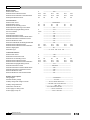
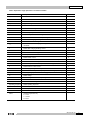
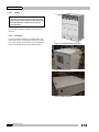
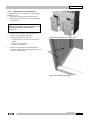
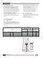
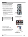
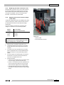
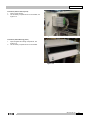
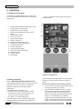
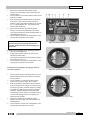
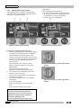
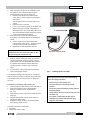
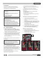
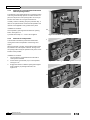
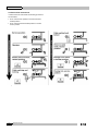
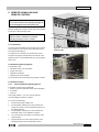
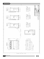
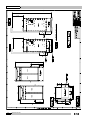
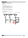
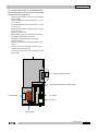
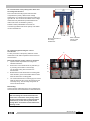
Xiria Product Family User manual 994.570 G01 05 User manual Xiria Product Family 994.570 G01 05 Eaton Industries (Netherlands) B.V. P.O. box 23, 7550 AA Hengelo, The Netherlands tel: +31 74 246 91 11 e-mail: [email protected] internet: www.eaton.eu/electrical Service emergency Eaton - Electrical Solutions & Services : tel: +31 74 246 68 88 Administrative data Issue number: G01 05 Date of issue: 24-05-2013 Translation of: Checked by Job title: Product Manager Name: A.R.A. Pikkert / B. ter Hedde Date: Initials: 2 994.570 G01 05 Xiria CONTENTS 1. GENERAL ............................................................................................... 5 1.1 Explanation of used warnings .............................................................................. 5 1.2 Safety relating to medium-voltage installations .................................................. 5 1.3 Tools, aids and protection equipment ................................................................. 5 1.4 Product standards and guidelines used .............................................................. 6 1.5 Product information .............................................................................................. 6 2. XIRIA SYSTEM DESCRIPTION ............................................................ 10 2.1 Xiria System description..................................................................................... 10 2.2 Cross-section, single line diagram and list of functions .................................. 11 2.3 Technical specifications, general ....................................................................... 12 3. INSTALLING THE UNIT ........................................................................ 13 3.1 3.1.1 3.1.2 Environmental requirements .............................................................................. 13 Transport, assembly and storage conditions .......................................................... 13 Ambient conditions ................................................................................................ 13 3.2 3.2.1 3.2.2 3.2.3 3.2.4 3.2.5 Installing the unit ................................................................................................ 13 Lifting .................................................................................................................... 14 Travelling .............................................................................................................. 14 Preparation prior to installation .............................................................................. 15 Setting up the unit ................................................................................................. 16 Securing to the floor .............................................................................................. 16 3.3 3.3.1 3.3.2 3.3.3 3.3.4 Connecting the cables ........................................................................................ 16 Types of cables ..................................................................................................... 16 Cable assembly instructions .................................................................................. 17 Replacing the cable connection cone .................................................................... 19 Applying test current and test voltage to the cable ................................................. 19 3.4 Connection of station earthing ........................................................................... 20 3.5 Access to secondary compartment .................................................................... 20 4. OPERATION .......................................................................................... 22 4.1 Details of control panel ....................................................................................... 22 4.2 4.2.1 4.2.2 4.2.3 Manual switching ................................................................................................ 22 Switching operating position on/off ........................................................................ 22 Switch cable earthing on/off .................................................................................. 24 Gaining access to cable ........................................................................................ 25 4.3 4.3.1 4.3.2 4.3.3 4.3.4 Interlocks ............................................................................................................. 27 Built-in interlocks ................................................................................................... 27 Earthed position interlock ...................................................................................... 27 Interlock for circuit-breaker/load-break switch opening button ................................ 28 Interlock for end position ....................................................................................... 28 994.570 G01 05 3 Xiria 4.4 4.4.1 4.4.2 4.4.3 Signals ................................................................................................................. 29 Voltage detectors .................................................................................................. 29 Overcurrent indicator............................................................................................. 29 Trip indicator ......................................................................................................... 29 4.5 Short-form instructions ...................................................................................... 30 5. REMOTE SIGNALLING AND REMOTE CONTROL ............................. 31 5.1 Connection .......................................................................................................... 31 5.2 Remote signalling (option) ................................................................................. 31 5.3 5.3.1 5.3.2 Remote control .................................................................................................... 31 24 V DC Remote tripping (option) .......................................................................... 31 24 V DC Remote closing (option) .......................................................................... 32 5.4 24 V DC Tripping for external protection ........................................................... 32 5.5 Local closing ....................................................................................................... 32 6. INSPECTION AND MAINTENANCE ..................................................... 33 6.1 Introduction ......................................................................................................... 33 6.2 6.2.1 6.2.2 6.2.3 6.2.4 6.2.5 6.2.6 Inspections .......................................................................................................... 33 Inspecting cable connections ................................................................................ 33 Inspecting switching functions ............................................................................... 33 Inspection of the moisture absorbing agent ........................................................... 34 Testing voltage detection ...................................................................................... 34 Inspecting the protection relay .............................................................................. 34 Inspecting the overcurrent indicator ....................................................................... 34 6.3 6.3.1 Decommissioning the unit .................................................................................. 34 Material processing after dismantling .................................................................... 34 7. ACCESSORIES AND OPTIONS ........................................................... 35 7.1 Supplied accessories .......................................................................................... 35 APPENDIX 1 – FLOOR PLANS ....................................................................... 39 APPENDIX 2 – VOLTAGE DETECTING SYSTEM (WEGA) ........................... 45 APPENDIX 3 – ORION 3.0............................................................................... 48 APPENDIX 4 – SHORT CIRCUIT INDICATOR ............................................... 49 APPENDIX 5 – TARIFF METERING 12KV ...................................................... 50 4 994.570 G01 05 Xiria 1. GENERAL The user must have authority to perform switching operations, which means being qualified in accordance with locally applicable guidelines, government legislation and inhouse company regulations with respect to the operation of medium-voltage installations. Legal and other regulations and documents pertaining to accident prevention, personal safety and environmental protection must be observed. Operations involving the repair of the switchgear unit are to be carried out by or under the responsibility of Eaton. Information with respect to these operations is, therefore, not included in this manual. suitable clothing which fits the body closely. The person in charge of the operations must ensure that all requirements, regulations and instructions are complied with. The Xiria unit has been designed to ensure that it exceeds applicable regulations. Furthermore, primary component enclosures are arc-resistant and interlocks have been fitted to prevent dangerous operations. Operations when the unit has been isolated Switching off prior to carrying out operations on an isolated system is subject to a number of essential requirements. 1. switching off; 2. 3. 4. 5. complete isolation; protection from reactivation; checking whether the unit is dead; provide short-circuit proof protective earthing and a 6. visible work-in-progress earth when needed. provide protection with respect to active components in the vicinity. 1.1 Explanation of used warnings The manual uses the following names and signs to highlight important (safety) information: Safe layout of the work area LIFE HAZARD This warning indicates that non observance of the specified (safety) instructions WILL result in serious and permanent bodily injury or even Ensure that access and escape routes are free at all times. Do not leave flammable materials in or near access and escape routes. Flammable materials must not be stored in areas which could be affected by arcs. death. In the event of a fire Never attempt to extinguish a fire on the switchgear unit before it is completely dead, this applies to both primary and secondary switchgear. Even if non-conducting WARNING This warning indicates that non observance of the specified (safety) instructions COULD result in serious bodily injury or even death. NOTE This note provides the user with additional information. The user's attention is drawn to possible problems. TIP Tips provide the user with suggestions and advice on how to make certain tasks easier or more convenient. 1.2 Safety relating to medium-voltage installations LIFE HAZARD Operations on medium-voltage installations can be life threatening if the necessary procedures are not observed. Always take suitable precautions before working on a medium-voltage installation. All personnel involved in operations carried out on, with or near electrical installations require to have been instructed on the safety requirements, safety rules and instructions applicable to the operation of the installation. Personnel must wear extinguishing materials are used, electricity may pass through the extinguishing equipment. Never extinguish a fire on the unit with water. Prevent water from flowing into the unit. Keep well clear of the unit while the fire is being extinguished in the area around the unit. 1.3 Tools, aids and protection equipment Tools, aids and protection equipment must meet the requirements of national and international standards insofar as they are applicable. Drawings and documents Recent documents of the electrical installation must be available in order to gain sufficient understanding of the schematic layout of the switchgear unit. Warning signs If necessary, suitable warning signs shall be placed on the switchgear unit during operations to highlight possible hazards. The warning signs must comply with the applicable standards, insofar as they apply. Performing measurements safely on the unit Suitable and safe measuring equipment must be used for measuring safely on the unit. These instruments must be checked before and after use. The instruments must also be inspected periodically in accordance with the applicable regulations. 994.570 G01 05 5 Xiria 1.4 Product standards and guidelines used Table 1: Current product standards used Standard Title IEC62271-1 Common specifications for high-voltage switchgear and control gear standards IEC62271-100 High-voltage alternating-current circuit-breakers IEC62271-102 Alternating current disconnectors and earthing switches IEC62271-103 High-voltage switches IEC62271-200 A.C. metal-enclosed switchgear and control gear for rated voltages above 1 kV and up to and including 52 kV IEC62271-304 Additional requirements for enclosed switchgear and control gear from 1 kV to 72.5 kV to be used in severe climatic conditions IEC60529 Degrees of protection provided by enclosures IEC60044-1 Instrument transformers - Part 1: Current transformers IEC60044-2 Instrument transformers - Part 2: Inductive voltage transformers EN50181 Plug-in type bushings above 1 kV up to 36 kV ISO 9001-2000 Quality ISO 14001 Environmental management 1.5 Product information The unit is equipped with type plates on the inside walls of the cable connection compartments (see Figure 1-1 to Figure 1-6). The panel type plate includes: switch type; technical specifications; serial number and year of manufacture. Eaton Industries (Netherlands) BV Medium Voltage P.O. box 23, 7550 AA Hengelo, The Netherlands M.V. SWITCHGEAR IEC 62271-200 system: XIRIA r2.9 AIR INSULATED Serialno: 1034XIRA290850041 Ur Ir 24 kV 630 A IAC AFL Up Ik 125 kV 16 kA Ua w.o. no.:539660 Year of man.: 2010 Ud Ip 50 kV 40 kA fr 50/60 Hz tk 1s 24 VDC Main switching device: 16kA-1s Figure 1-1: Example of system type plate CIRCUIT-BREAKER type: Ur Ik 24 kV 16 kA Isc Ua IEC 62271-100 16 kA Up tk 125 kV 0.6 s DCcomponent 35% GENERAL PURPOSE SWITCH type: NVR12AA-2402 R2.9 SVR14AA-2406 IEC 62271-102 R2.9 Ir 200 A Ur 24 kV Up 125 kV Ir 630 A Ic 31.5 A Ik 16 kA tk 1s Ima 16 kA I1 630 A I2a 630 A I4a 31.5 A I6a 240 A I6b 55 A n 100 Lma 16 kA 24 VDC Operating sequence O-3 min-CO-3 min-CO Ua Classification E2 C2 Classification E3 24 VDC For more information refer to main nameplate Figure 1-2: Example of panel type plate for circuit-breaker 6 994.570 G01 05 Figure 1-3: Example of panel type plate for load-break switch Xiria CURRENT TRANSFORMER IEC 60044-1 type: Make: CTB 90 75/5 A 5 VA EATON L1-L2-L3 CURRENT TRANSFORMER IEC 60044-1 type: Make: WIC1-W3H1 S1 – S2 Cl. 0,2 ext. 120% Cl. 0,2 ext. 120% /A 50 A Ik 20 kA tk 28,8/0,288 A Test winding 10 A 3 s. L1 – L2 – L3 3s Figure 1-4: Rating plate of a current transformer for metering Figure 1-5: Rating plate of a current transformer for protection VOLTAGE TRANSFORMER IEC 60044-2 type: UNECAK 12 D1.E Make: A-N 10000/√3 a1-n 100/√3 7,5 V Cl. 0,2 Sth. 400VA da-dn 100/3 30 VA Cl. 3P Sth. 100VA 12-28-75 kV C-D For system information refer to main plate VA Cl. 0,2 ext. 120% Ip L1 – L2 – L3 0.1 VA Cl. 5P80 /A VA 28,8/0,075 A ELEQ ELEQ 1,9 Ur - 8h Figure 1-6: Rating plate of a voltage transformer Technical data: General: Rated voltage Impulse withstand voltage Power frequency withstand voltage kV kV kV-1m 3.6 40 10 Rated frequency Hz ----------------------50-60---------------------------------- 7.2 60 20 12 75 / 95 28/38/42 17.5 95 38 24 125 50 Degree of protection in service Degree of protection with doors/covers open ---------------------IP31D-----------------------------------------------------IP2X----------------------------------- Classification according to IEC 62271-200: Loss of service continuity ----------------------LSC2B-------------------------------- Partition class Internal Arc Classification (IAC) Internal arc resistance Internal arc resistance with absorber ----------------------PM----------------------------------------------------------AFL----------------------------------20-1 20-1 20-1 20-1 20-1 16-1 16-1 16-1 16-1 16-1 kA-s kA-s Ambient air temperature range Maximum altitude Average Watt losses per panel 0 C m W ------------------- -25 +40 ---------------------------------------------------1000--------------------------------------------------------100 ------------------------------------ Sound emission dB(A) ----------------------<70------------------------------------- 994.570 G01 05 7 Xiria Busbar system: Rated normal current A ----------------------630----------------------------------- Rated short-time withstand current Rated short time withstans current alternative Rated peak withstand current kA-s kA-s kA 20-1 20-3 50 Circuit-breakers: Rated normal current Rated breaking current A kA ---------------------200/500/630------------------------20 20 20 20 20 Rated short-circuit making current Rated Capacitive Switching Current Class Rated Cable Charging Breaking Current DC Time Constant kA 50 50 50 50 50 ----------------------C2----------------------------------------------------------31.5--------------------------------------------------------45-------------------------------------- DC Component Mechanical Endurance Class Mechanical Endurance Class as Earth Switch Mechanical Endurance Class Disconnector % Electrical Endurance Class Electrische classificatie als aardingsschakelaar Rated short-time withstand current Rated short-time withstand current alternative Minimum tripping time Mechanism type Load break switches: Rated normal current Rated active load break current Rated short-circuit making current Rated short-time withstand current Rated short-time withstand current alternative Rated Cable Charging Breaking Current Mechanical Endurance Class Mechanical Endurance Class as Earth Switch Mechanical Endurance Class Disconnector Electrical Endurance Class Electrical Endurance Class as Earth Switch Remote control options: Wiring diagram Standard auxiliary voltage Auxiliary voltage with voltage converter A msec kA kA 20-1 20-3 50 20-1 20-3 50 20-1 20-3 50 20-1 20-3 50 ----------------------<20----------------------------------------------------------M1----------------------------------------------------------M1----------------------------------------------------------M0----------------------------------------------------------E2-----------------------------------------------------------E2------------------------------------20-1 20-1 20-1 20-1 20-1 20-3 20-3 20-3 20-3 20-3 msec ----------------------80----------------------------------------------- O - 3 min - CO -3 min - CO -------------- A A kA -----------------------630---------------------------------------------------------630----------------------------------50 50 50 50 50 kA-s kA-s A 20-1 20-1 20-1 20-1 20-1 20-3 20-3 20-3 20-3 20-3 ----------------------31.5------------------------------------------------------M2 5000x----------------------------------------------------M0----------------------------------------------------------M0----------------------------------------------------------E3-----------------------------------------------------------E2------------------------------------- -------------------R34S30291----------------------------- Auxiliary voltage tolerances ---------------------24 V DC----------------------------------------36-72 V DC & 36-60 V AC --------------------------100-353 V DC & 100-240 V AC --------------------------------- +10% -30% ---------------------------- Watt losses controller K7 Power supply for closing motor Power supply for trip coil ----5 W continuous when idle --------------------------------------55 W 15 seconds-----------------------------------------40 W 100 msec.------------------------- 8 994.570 G01 05 Xiria Table 2: Explanation oftype plate data in accordance with IEC Variable Description system Unit - r. Release - IEC IEC reference - type Type switching device - serial no. Serial number - year of man. Year of manufacturing - w.o.no. Works order number - fr Rated frequency Hz I1 Rated mainly active load breaking current A I2a Rated distribution line closed-loop breaking current A I4a Rated cable-charging breaking current A I6a Rated earth-faulth breaking current A I6b Rated cable- and line-charging breaking current under earth-fault conditions A Ic Rated cable-charging breaking current A Ik Rated short-time withstand current kA Ima Rated short-circuit making current kA Ip Rated peak withstand current kA Ir Rated normal current A Ir T-off Rated normal current of the circuit-breaker in the transformer panel A Isc Rated short-circuit breaking current kA n Number of operations for mainly active load breaking - tk Rated duration of short-circuit s Ua Rated supply voltage of auxiliary circuits V Ud Rated short-duration power-frequency withstand voltage (1 minute) kV r.m.s. Up, Uw Rated lightning impulse withstand voltage (peak) kV Ur Rated voltage kV Ur.t Rated voltage factor and corresponding rated time Vs Isolation level Rated isolation level kV Class M, E, C Classification according to IEC - Operating sequence Rated operating sequence - VA Rated output VA CL Accuracy Class - IAC Internal Arc Classification - AFLR Authorised personal only - F = Front L = Lateral R = Rear 994.570 G01 05 9 Xiria 2. XIRIA SYSTEM DESCRIPTION 2.1 Xiria System description The Xiria switchgear panels are available for applications up to 24kV. The system is fully metal enclosed and a highly compact and safe unit is achieved using high-quality internal insulation. All live primary components of the unit and the main components of the drive mechanisms are housed in a fully sealed enclosure. This prevents any dust, moisture and other environmental factors from affecting the proper operation of the system. The enclosure is also arc resistant and thus provides conditions of optimum safety for the operator. The cable compartments are available as an option in arc-proof configuration. Different panel versions are available, among others: a vacuum load-break switch for ring cable connections; a vacuum circuit-breaker for the protection of mains transformers and cable connections. The versions can be supplied in any combination and sequence. The Xiria panels includes immediately visible position indication using viewing windows (1) on the control panel, see Figure 2-1. The separation between cable and busbar system and the position of the vacuum interrupter are directly visible through the viewing windows. This also provides safe, visible and integrated earthing in combination with the short-circuit proof load-break switch or circuit-breaker. Cables are connected with cable connection cones suitable for use with plugs. 10 994.570 G01 05 Xiria 2.2 Cross-section, single line diagram and list of functions 1 Cable connected to the busbar Figure 2-1: Panel cross-sections and single line diagrams Cable connected to earth 1. Viewing window 2. Earth contact change-over switch 3. Busbar contact change-over switch 4. Main busbars 5. Change-over switch 6. Vacuum interrupter 7. Control panel 8. Cable connection The position of the disconnector can be viewed via the windows (1). Functions, load-break switch panel Connect cable to busbar. Functions, circuit-breaker panel Connect cable to busbar. Disconnect cable. Connect cable to earth. Test cable. Disconnect cable. Connect cable to earth. Protect outgoing feeder from overcurrents. Test cable. 994.570 G01 05 11 Xiria 2.3 Technical specifications, general Item Explanation Weight of the heaviest transport unit Specification Nett (kg) Gross (kg) 1 panel 320 350 2 panels 350 380 2 panels with plinth 410 440 3 panels 430 460 3 panels with plinth 520 550 4 panels 550 590 4 panels with plinth 670 710 5 panels 660 710 5 panels with plinth 810 860 Metering panel (exclusive VT’s and CT’s) 250 280 Metering panel (inclusive VT’s and CT’s) 400 430 Unit dimensions Width (mm) Height (mm) Height incl. plinth (mm) Depth (mm) 1 panel 500 1325 1575 600 2 panels (block type) 760 1305 1555 600 3 panels (block type) 1110 1305 1555 600 4 panels (block type) 1460 1305 1555 600 5 panels (block type) 1810 1305 1555 600 Metering panel 850 1325 1575 750 1 panel 500 1600 1850 800 2 panels (block type) 1200 1600 1850 800 3 panels (block type) 1200 1600 1850 770 4 panels (block type) 1555 1600 1850 770 5 panels (block type) 1860 1600 1850 800 Metering panel 1200 1600 1850 800 Lifting and transport The unit is fitted with special lifting fixtures. The unit may only be facilities lifted by these fixtures, see section 3.2.1 Facilities to secure the The base of the unit has openings to secure the unit to the floor, Xiria see section 3.2.5 Unit dimensions incl. packing 12 994.570 G01 05 See delivery note for the exact value Refer to the floor plan in Appendix 1 Xiria 3. INSTALLING THE UNIT 3.1 Environmental requirements 3.1.1 Transport, assembly and storage conditions If the temperature and humidity conditions specified in the order cannot be guaranteed during the transport, assembly and storage of the unit, preventive measures must be taken in consultation with Eaton. Care should be taken not to damage the unit, even if the packaging has not been removed. The packaging is only During shipment all switches are to be switched to the earthed position (switch closed and change-over switch in earthed position). Special preventive measures may be required to avoid: moisture absorption in the packaging as a result of rain, snow or condensation; vibrations during transport; damage to the pressure relief valves. If the unit is shipped by air, it should be carried in a cargo bay in intended to prevent minor damage. 3.1.2 which the air pressure is maintained at 1 atmosphere ±10% throughout the entire flight. Ambient conditions Item Condition Requirements for the floor and wall of the building. Minimum permissible floor loading 500 kg/m2. The floor must be level and have a smooth finish to ensure that the carrier frame of the unit is evenly supported Provide cable recesses according to the floor plan (see Appendix 1). The cable recesses in the floor can be sealed to prevent rising damp. Polyurethane with a compact cellular structure can be used for this. Requirements for clearances around the At least 60 mm at the top. This is equivalent to a minimum height of 1365 mm for the operating area. Xiria: Left and right hand side minimum 50 mm. Sufficient space should be available at the front and along the entire length of the unit for operational purposes and to be able to work safely with the normal test equipment. When the IAC classification is applied according to IEC62271-200 an arc channel shall be taken into consideration, see section 3.2.4. Requirements for escape routes When the unit is installed in an accessible area, escape routes shall be provided according to the local requirements. Ambient conditions (IEC 62271-1) Class –25 °C indoor. 3.2 Installing the unit The unit is supplied packaged on a wooden pallet. Provision for lifting is fitted to the top of the unit, see Figure 3-1. The unit is secured to the pallet with bolts. Leave the unit on the pallet as long as possible, preferably until it reaches the assembly location. The unit can be handled simply and safely providing the pallet and standard lifting equipment are used. The installation of the unit includes the following actions: 1. Lifting. 2. 3. 4. 5. Travelling. Preparation prior to installation. Installing the unit. Securing to the floor. 994.570 G01 05 13 Xiria 3.2.1 Lifting 1 WARNING The person in charge of lifting the Xiria unit must hold a certificate issued by the relevant authorities to certify that he/she is authorised to carry out these operations. After installation the lifting equipment (1) must not be removed. 3.2.2 Travelling The unit is supplied packaged on a wooden pallet. This means that it can be moved simply and safely on a pallet truck. Leave the unit on the pallet as long as possible and carry it on the pallet right up to the assembly location. Figure 3-1: Fitting the lifting equipment Figure 3-2: Single panel Figure 3-3: Metering panel 14 994.570 G01 05 Xiria 3.2.3 Preparation prior to installation The location of the unit is required to meet the conditions stated in par. 3.1.2. 1. Remove the packaging and check the contents. 2. Remove the doors of the left- and right-hand panels, see Figure 3-4. TIP The door can only be removed if the panel is in the 'Cable earthed' position. See procedure in section 4.2.2. 3. Remove the 4 fixing bolts (1) (2 either side), see Figure 3-5 and then remove the pallet. 4. When positioning the unit check that: the cable openings in the floor are in the correct position; the floor is clean and level; Figure 3-4: Opening the cable access door the unit is not damaged. 5. Slide the unit across the floor to its final location, if necessary. Apply a lever to the base plinths only. Take care not to damage the unit. 1 Figure 3-5: Location of fixing bolts 994.570 G01 05 15 Xiria 3.2.4 Setting up the unit The Xiria system has been designed in accordance with the recommendations set out in IEC 62271-200 which theoretically prevents internal faults from occurring. Moreover, when set up correctly, a Xiria unit will comply with this IEC standard for setting up with an arc channel. The pressure relief flaps in the Xiria enclosure are located at the rear and bottom of the unit, and they can be connected to the arc channel of the building. The pressure relief flaps at the rear can be sealed off using a cover plate available separately as an option. For further information see also the floor plan drawings in Appendix 1. The following rules apply to a set-up with an arc channel: The channel is to be connected to a location where no danger can occur to personnel. The bore of the channel is to be a minimum of 0.15 m2 and the channel itself requires to be capable of withstanding overpressure of at least 0.5 bar. The area the arc channel is connected to must be capable of withstanding the overpressure also. 3.2.5 Securing to the floor The Xiria unit must be fixed to the floor in four locations. The drilling pattern for fixing and cable holes is included in Appendix 1, 'Floor plan'. Use washers under bolt heads/nuts. 3.3 Connecting the cables 3.3.1 Types of cables Single-core cables can be connected to the unit. Three-core cables can be connected, if the dimensions of the associated splitting point fit into the cable compartment. See for the available space for cable connection plugs Table 3. Table 3: Maximum dimensions for cable connectors inside the Xiria cable compartment Cable compartment type Panel type Door lock Non arc Arc resistant resistant A (mm) A (mm) B (mm) C (mm) Circuit-breaker 200 A Elbow plug connector type A 238 240 36 37 Circuit-breaker 500 A Bolted T connector type C 195 197 36 37 Circuit-breaker 630 A Bolted T connector type C 195 197 36 37 Load break switch 630 A Bolted T connector type C 277 279 36 37 Figure 3-6: Xiria cable compartment 16 994.570 G01 05 Xiria Table 4: Short-circuit capacity in relation to cable cones used Cone type EN 50181 I [A] Maximum short-circuit current Plug type Cable type Load-break switch C 630 17.5-24kV 16kA-1s 3.6-12kV 20kA-1s bolted T-plug M16 Cu/Al XLPE Cu/Al XLPE Circuit- A 200 17.5-24kV 16kA-0.6s plug type Cu/Al XLPE 3.6-12kV 20kA-0.4s L plug Cu/Al XLPE 17.5-24kV 16kA-1s bolted T-plug Cu/Al XLPE 3.6-12kV 20kA-1s M16 Cu/Al XLPE breaker Circuit- C 500 breaker 3.3.2 Cable assembly instructions Strain relief Strain relief prevents mechanical forces from being transmitted to other parts of the unit via the cable connection point. Each panel is provided with three single phase plastic cable clamps or one three phase plastic cable clamp (Figure 3-7). Assembly (standard) WARNING At delivery each cable cone type C is provided with a “temporarily” mounted allen key transport Figure 3-7: Cables with plastic cable clamps bolt M16 x 30. These bolts must be removed before connecting the cable. Plinths can be removed for each panel when fitting the cables if so desired. Connect the cables to ensure that no mechanical forces are created at the cable connection point. The maximum torque for a C-type cone is 70 Nm. The weight of the cable and tensile forces originating from the cable must be absorbed by the cable clamp blocks on the cable support. Secure all cables using cable clamp blocks. This is in order to enable the short-circuit forces to be absorbed in the event of any short-circuit occurring. Seal all cable recesses in the floor properly. Use polyurethane with a compact cellular structure, for instance. This will protect the cable connection compartment from rising damp and vermin. The cable clamp blocks are mounted on an adjustable frame in the cable connection compartment. The bolts through the plastic cable clamps must be tightened to a torque of 20 Nm. 994.570 G01 05 17 Xiria Assembly steps if current transformers are installed around the primary cable The same steps should be followed as described at the standard assembly. For easy connection of the primary cables the current transformers in the cable compartment can be removed and remounted. For this the following steps should be taken: 1. Open the cable compartment according to the standard instructions. Remove the current transformers for protection (A) by removing the two bolts on the front (B). The 2. secondary wiring does not need to be disconnected. Behind these current transformers a mounting plate fixed with bolts ( C) becomes visible. Remove these bolts and remove the mounting plate. 3. 4. The current transformers for metering (D) can now be lifted and removed, also remove the tywrap from the secondary wiring. The secondary wiring does not need to be disconnected. 5. Lead the primary cables through the current transformers and remount the current transformers as described above. 1 2 3 4 Figure 3-8 1. Current transformers for protection REMARK After remounting the current transformers the 2. Current transformers for metering 3. Cable clamps 4. Cable side voltage transformers earth screen connections of the primary cables must be connected to earth via the premounted earth wires (F). In this case any earth current through these connections will not influence the metering results. Figure 3-9 Connection of the primary cables when cable side voltage transformers are installed Due to the limited mounting space inside the cable compartment the primary cables and the voltage transformers are connected with connectors make Tyco type RSTI 58. The connectors and cables for the voltage transformers are pretested and preassembled on the cable cones of the circuit-breaker. Parallel on these preassembled connectors the connectors (type RSTI CC58) for the primary main cables can be mounted at site. Figure 3-10: Cable connector 18 994.570 G01 05 Xiria 3.3.3 Replacing the cable connection cone Damaged cable connection cones can be easily replaced by our service department. A different type of cone can also be fitted in the circuit-breaker panel at a later stage. Two types are available, A and C in accordance with EN 50181. Contact Eaton for further details. 3.3.4 Applying test current and test voltage to the cable 1 If cable side voltage transformers are installed in the panel make sure the primary cables are disconnected from the pre-assembled connectors for the cable side voltage 2 transformers. The unit is suitable as standard for the following test voltages, for a maximum of 10 minutes per phase: System voltage Test voltage (DC or AC-peak value) 24 kV 60 kV 17.5 kV 12 kV 7.2 kV 45 kV 30 kV 30 kV WARNING Test accessories are needed to apply test current and test voltage to the connected cables. 1. 2. 3. 4. 5. Figure 3-11 1. Primary cable 2. Pre-assembled connectors Earth the unit in accordance with section 4.2.2. Install the specified test accessories in accordance with the instructions of the plug and test accessory suppliers. The switch must not be activated until you and the person responsible for the unit are satisfied that the earthed connection can be opened safely with the switch. The unit requires to be earthed again in accordance with section 4.2.2 before the test accessories are removed on completion of the work. Safety precautions: The unit must be isolated from any possible normal source of supply, other than the test device. Under no circumstances must it be possible for the unit to be powered up again by any source other than the external supply used for voltage testing. The applicable safety measures must be applied with respect to all personnel present during voltage testing. 994.570 G01 05 19 Xiria 3.4 Connection of station earthing The Xiria unit can be connected either to the left or to the right of the station earthing. An earth bar, to which the earth screens of the power cables and the system earth can be connected, is located at the rear of every cable connection compartment. See Figure 3-12. The earth bar is provided with 10 mm holes on both ends outside the unit for the connection of the system earth. Three M8 nuts are mounted on the earth bar in each cable compartment for the connection of the earth screens of the power cables. Figure 3-12: Earth bar 3.5 Access to secondary compartment The front plate requires to be removed in order to gain access to the secondary compartment. Procedure (standard) 1. Remove the screws at the bottom of the front plate, see Figure 3-13. 2. 3. Move the bottom of the front plate forward, lower it and remove it, see Figure 3-14. The secondary compartment is now accessible. Figure 3-13: Position of front plate fixing screws Figure 3-14: Removing the front plate 20 994.570 G01 05 Xiria Procedure (Xiria E with top-unit) 1. Open top-unit with key. 2. The secondary compartment is now accessible, see Figure 3-15. Figure 3-15 Procedure (Xiria Metering panel) 1. Open integrated low voltage compartment, see Figure 3-16. 2. The secondary compartment is now accessible. Figure 3-16 994.570 G01 05 21 Xiria 4. OPERATION 4.1 Details of control panel The Xiria unit is equipped with two types of control panel, one for the load-break switch panel and one for the circuitbreaker panel. 1. 2. Earthed position interlock for padlock max. 12 mm. Padlock facility for off pushbutton 3. 4. 5. Off pushbutton with anti-reflex flap Electrical closing pushbutton for motor control (option) Switch position indicator 6. 7. 8. 9. Switch control point Switch function indicator Selector control knob Change-over switch control point 10. 11. 12. 13. Change-over switch position indicator Trip indicator CB (option) Ammeter CB (option) Cable side voltage detector 14. 15. 16. 17. Short-circuit indicator LBS (option) Inspection window Moisture indicator Door interlock Figure 4-1 provides a summary of the control units on the control panels. Figure 4-1: Control panels 4.2 Manual switching 4.2.1 Switching operating position on/off In the operating position the cable is connected to the main busbar of the unit. Here, the switch (5) is ON and the change-over switch (8) is in the busbar position. Initial position: In the neutral position (see Figure 4-2): the switch is OFF, see switch (4) position indicator; the change-over switch is in earthed position, see change-over switch (9) position indicator; The selector (7) is in the central position. This initial position has been selected to ensure that all switching operations are described. If the change-over 22 994.570 G01 05 switch is already in the busbar position, for instance during switching on, switching with this change-over switch is omitted. Procedure for switching on the operating position 1. Turn the selector (7) clockwise until the control point of the change-over switch (8) is revealed. 2. Place the operating handle with the arrow pointing down in the control point of the change-over switch (8). Switch the change-over switch to the busbar position by turning the handle anti-clockwise as far as it will go, i.e. to approximately 1900. Additional resistance will be noticeable towards the end of this rotation. The handle cannot be removed until busbar position of the change-over switch has been reached. Xiria 3. Remove the handle and check that the position indicator (9) of the change-over switch indicates the busbar position. 4. Turn the selector anti-clockwise until the switch control point (5) is revealed. Place the operating handle with the arrow pointing up in the switch control point (5). Switch the cable to 5. 6. busbar by turning the handle clockwise as far as it will go, i.e. to approximately 1900. The mechanism will switch audibly at that point. Remove the handle and check that the position 7. indicator (4) of the switch indicates the ON position. In the viewing window the closed operating position is also visible (see Figure 4-3). Turn the selector (7) back to the central position, both openings (5) and (8) will then be covered. NOTE On performing wrong switching operations the operation handle will bend to avoid damaging the mechanism. Figure 4-2:Neutral position Procedure for switching off the operating position 1. Press the opening button (3). 2. Check that the position indicator (4) of the switch indicates the OFF position. 3. In the viewing window the opened operating position is also visible, see Figure 4-4. Turn the selector (7) back to the central position, both openings (5) and (8) will then be covered. Procedure for switching the operating position to the neutral position 1. Turn the switch off with the opening button (3). Check that the position indicator on the switch (4) indicates the OFF position. 2. Turn the selector (7) clockwise so that the control point for the change-over switch (8) is revealed. Place the operating handle with the arrow pointing up in the control point of the change-over switch (8). Turn 3. Figure 4-3: Closed operating position the change-over switch in earthed position by rotating the handle1900 clockwise until you start to feel some resistance. Additional resistance will be noticeable towards the end of this rotation. The handle cannot be 4. 5. removed until earthing position of the change-over switch has been reached. Remove the handle and check that the position indicator (9) of the change-over switch indicates the Figure 4-4: Opened operating position earthed position. Turn the selector (7) back to the central position, both openings (5) and (8) will then be covered. 994.570 G01 05 23 Xiria 4.2.2 Switch cable earthing on/off In the operating position, the cable is connected to the main busbar of the unit; the switch is ON and the changeover switch is in the busbar position. Figure 4-5: Panel in neutral position Initial position: In the neutral position (see Figure 4-5): the switch is OFF, see switch (4) position indicator; the change-over switch is in earthed position, see position indicator of change-over switch (9); selector (7) is in the central position. Figure 4-6: Panel in earthed position Procedure for switching cable earthing on 1. Check the position indication to verify that the changeover switch is in the earthed position. An additional option is available to inspect the position of the change-over switch through windows (14) at the front , see Figure 4-5. Check the position of all three phases: use a torch to provide additional light through an adjacent window; check the position of the change-over switch; Figure 4-7 shows the change-over switch in the Figure 4-7: Change-over switch in the earthed position earthed position; Figure 4-8 shows the busbar position; repeat this procedure for the other two phases. If the panel is not in neutral position, put it in this 2. position now, see section 4.2.1. Turn the selector anti-clockwise, the control point of the switch (5) is revealed. Use the built-in voltage detector to check that the 3. 4. cable is dead. Arrows and dots visible: Detector is functioning correctly and the cable is live; Arrows and dots not visible: cable is dead. NOTE The visible dot shows that the detector is functioning correctly in accordance with the demands for voltage detecting systems as described in VDE 0682 art. 415. This is a continuous internal function check. 24 994.570 G01 05 Figure 4-8: Change-over switch in the busbar position Xiria 5. When the arrows and dots are not visible then check the operation of the voltage detection using the voltage detection tester (18) see Figure 4-9: a. b. c. 6. insert the tester plugs in the contact sockets “earth” and L1. Test the detector by pressing the tester button. The tested phase arrow and dot should now be present; repeat the test for L2 and L3. if one or more arrows and dots do not appear, this might be the result of a faulty voltage detector. 18 Should this be the case contact Eaton. Ensure by other means that the cable is dead before carrying out any further switching operations. When the arrows and dots are visible then the functionality of the voltage detector can be tested as follows: a. Connect a wire from the tester between the contact sockets “earth” and L1. The arrow and dot b. indication from this phase must disappear. Repeat this test with the phases L2 and L3. NOTE The detector also has a piezo test button on the front for testing the LCD screen only. 7. 8. Figure 4-9: Using the tester Earth the cable by turning the switch ON. Insert the operating handle with the arrow pointing up in the switch control point. Turn the handle 1900 clockwise. You will hear the mechanism switch. Remove the operating handle. The cable is now connected to earth. Put the selector in the central position so that both control openings are covered. The integrated earthing of the Xiria panel is now ON; the cable is earthed to be short-circuit proof through the switch. The earthed position can now be locked as described in par. 4.3.2. 4.2.3 Gaining access to cable NOTE When gaining access to the cable, the following basic rules apply at all times: • Disconnect the cable at both ends. Procedure for switching cable earthing off 1. 2. 3. 4. 5. Check whether the cable earthing can be switched off. Remove the padlock from the earthed position interlock (if it is still in place), as described in par. 4.3.2. Switch OFF the switch of the relevant panel with push button (3). Check that the position indicator on the switch (4) indicates the OFF position. Rotate the selector (7) back to the central position; both openings will be covered. • The panel must be in the closed earthed position. • Secure this internal earthing by locking it with a personal padlock. • Verify that the cable can never be made live from the other end. • On request a visible back-up earth can be installed in accordance with the cable plug supplier's instructions. The panel is back in the neutral state: switch OFF; change-over switch to earth. 994.570 G01 05 25 Xiria Procedure 1. Switch on the integrated cable earthing in accordance with the instructions in section 4.2.2. 2. To open the cable connection compartment: check, using the single line diagram and position indicators, whether the cable on the panel to be opened is earthed; open the cable connection compartment by lifting the door and moving it forward Figure 4-10. Put up a “cable earthed” warning sign. 3. 4. Use a high voltage tester to verify that the cable is dead. Follow the cable connection supplier's instructions. Figure 4-10: Opening the cable connection compartment NOTE The cable compartments are available as an option in arc-proof design. The cable access doors of this optional version are not interchangeable with the standard doors. 5. Now if requested a visible back-up earth can be installed by: connecting the earth terminal on the back-up earth to the earth bar in the cable connection compartment, see Figure 4-12; fit the earthing equipment, according to the plug supplier's instructions, to all three phases of the cable connection, see Figure 4-11. TIP It is still possible, however, to open the switch or Figure 4-11: Example of an isolated plug with an earthing point circuit-breaker in this situation. This may be necessary in order to measure the cable. If the switch requires to be interlocked against being closed on in this situation, the scissor-type interlock (section 4.3.4) can be used for this purpose. 6. The panel requires to be returned to the neutral position on completion of the operations. Proceed as follows: remove the back-up earthing equipment when this is mounted; connect the cable connection plugs according to the supplier's instructions; close the cable access door; remove any earthing interlocks fitted; open the switch. check the position indicator. TIP The above switching operations are summarised for experienced users in tables shown in section 4.5. 26 994.570 G01 05 20 Figure 4-12: Earth bar in the cable connection compartment Xiria 4.3 Interlocks The Xiria unit is equipped as standard with built-in interlocks to prevent accidental switching operations. These interlocks are mechanical interlocks. LIFE HAZARD Undesirable switching operations could result in the following: • danger to personnel (operating and service personnel); Turning off the switch with the opening button. Electrical disconnection of the switch by the protective relay. Opening the door of the cable compartment. The earthed position interlock can be installed if (see section 4.2.2): front of this button. • failure of power supply; • damage to the unit. the change-over switch is in the earthed position; the switch is ON; the cable access door is closed; the flap in front of the opening button is fully placed in The interlock is used as follows, see Figure 4-13 WARNING If a (switching) action cannot be achieved with normal operating force: 1. 2. • Check against section 4 whether 3. the action to be carried out is permissible; • Notify Eaton-ESS if the action is permissible according to the switching tables but cannot be accomplished with normal operating force. 4.3.1 Built-in interlocks The following interlocks have been applied: Interlock to prevent cable access from being opened if cable is not earthed. Note: Once the cable access has been opened, the panel can be switched off to carry out cable tests; this interrupts the cable-earth link. Interlock to prevent operation of the change-over switch when the circuit-breaker or load-break switch is active. In order prevent reflex attempts to switch off a shortcircuit after switching on, the opening button is equipped with an anti-reflex flap (1). A number of switching positions can also be interlocked with padlocks. WARNING After any temporary absence, check that the necessary interlocks and eventually mounted back-up earths are still in place. 4.3.2 4. 5. 6. Turn the selector (7) anti clockwise. Place the cover flap fully in front of the opening button (A) Pull part B to the front, part C will automatically move downward and part B stays in position (Figure 4-13 C). Put the hasp of the padlock (D) through the hole on the right (Figure 4-13 D). The hasp diameter can be 1-12 mm. The earth position is now interlocked, including the cable access door and the opening button. Put up a “cable earthed” warning sign if needed. Remove the interlock as follows: 1. Remove the padlock D (Figure 4-13 D). 2. Push part C upwards, part B will automatically move backwards (Figure 4-13 C). 3. The earth position interlock is removed. 7 A C B A Earthed position interlock The earthed position interlock is intended to prevent the cable earthing from being interrupted unintentionally. Cable earthing is achieved via the load-break/circuit breaker switch; it therefore requires to be locked against opening to be sure that the cable is earthed. Once this interlock has been installed, the following operations are no longer possible: C B D C Figure 4-13 994.570 G01 05 27 Xiria 4.3.3 Interlock for circuit-breaker/load-break switch opening button The interlock on the opening button is to prevent the switch from being unintentionally opened. Once this interlock is in place, the flap in front of the opening button can no longer be lifted. The switch can no longer be switched off manually. However, switching off by the protective relay, if fitted, or the optional remote control remains possible. This interlock can be applied in every position of the panel. Installation is as follows: Hook a padlock (19) through the hole below the opening button, see Figure 4-14. A paslock with a hasp of 1 – 12 mm can be applied. 4.3.4 Interlock for end position This interlock is intended to prevent the unintentional closing of the switch and operation of the change-over switch. When the interlock is in place, the operating handle cannot be inserted in the control points. However, turning off via the opening button and by the protective relay of the circuitbreaker remain possible. 19 Figure 4-14: Padlock on opening button 7 21 Installation is as follows: 1. Turn the selector (7) anticlockwise until the switch control point is revealed. 2. Fit the scissor-type interlock (21) in control aperture, 3. Figure 4-15: Installing the scissor-type interlock see Figure 4-15. Engage the scissors so that the openings are aligned. Pass a padlock (19) through both holes, see Figure 4-16. 19 Figure 4-16: Padlock on scissor 28 994.570 G01 05 Xiria 4.4 Signals The Xiria unit features voltage detectors on the cable side and can be fitted with overcurrent indicators and trip indicators as options. 4.4.1 Voltage detectors 12 The Xiria unit features voltage detectors in the control panel (12) conform IEC 61243-5 with LRM interface. The voltage detector includes an LCD screen with indication arrows and dots, one for each phase, see Figure 4-17. These arrows and dots are present when the Figure 4-17: Voltage detectors cable is live. The voltage detector detects wheather the operating voltage is present at the cable connection of the panel concerned. NOTE The visible dot shows that the detector is functioning correctly in accordance with the demands for voltage detecting systems as described in VDE 0682 art. 415. This is a continuous internal function check. In combination with the ORION 3 tester the voltage detectors can also be used for phase comparison between two adjacent live cables. See appendix 4 for further information. 13 4.4.2 Overcurrent indicator The overcurrent indicator (13), see Figure 4-18 is activated by an overcurrent. See Appendix 5 for further information. Figure 4-18: Overcurrent indicator 4.4.3 Trip indicator 10 The trip indicator (10), see Figure 4-19, indicates whether the switch has been switched off by the protection relay. Resetting can be done by hand via the reset button on the front. Figure 4-19: Trip indicator 994.570 G01 05 29 Xiria 4.5 Short-form instructions In these short-form instructions the following procedures are described: From closed service position to closed and locked earthed position. From closed and locked earthed position to closed service position. Figure 4-20: Short-form instructions 30 994.570 G01 05 Xiria 5. REMOTE SIGNALLING AND REMOTE CONTROL TIP For correct connection and operating voltages see the circuit diagrams delivered with the unit. Remote signalling and electric remote control are available as options for Xiria switchgear units. 1 NOTE Remote control is suitable for a maximum switching frequency of once a minute. 2 5.1 Connection The unit concerned is fitted in the secondary space behind Figure 5-1: Secondary space with cable duct and terminal strips the front plate or in the top-unit with a cable duct (2) and secondary terminal strip (1). The wiring to be connected to the terminal strip can be brought in through the side wall either from the left or the right-hand side or via the flexible plate (3) in the top plate of the top-unit. 3 5.2 Remote signalling (option) The positions of the: load-break switch or circuit-breaker; change-over switch; (optional) trip indicator; (optional) overcurrent indicator; 1 2 are connected to the terminal strip using auxiliary contacts. Figure 5-2 5.3 Remote control 5.3.1 24 V DC Remote tripping (option) The panels concerned are provided with: auxiliary contacts as described under remote signalling; a controller; a trip coil. If the supply voltage < > 24 V DC, then an optional universal voltage converter is mounted. For on-site commissioning: 1. 2. Check that the power supply is live. Use the position indicator (9) to check whether the change-over switch is fully in the busbar position or in the earthed position. 3. Use the position indicator (4) to check whether the load-break switch or circuit-breaker is closed. The control knob for the selector (7) should be in the central position. 4. 5. Tripping will follow once the closing contact on the relevant terminals of the terminal strip is closed. 994.570 G01 05 31 Xiria 5.3.2 24 V DC Remote closing (option) The panels concerned are provided with: auxiliary contacts as described under remote signalling; a controller; a trip coil; a closing motor; a closing pushbutton on the frontside of the panel. If the supply voltage < > 24 V DC, then an optional universal voltage converter is mounted. For on-site commissioning: 1. Check that the power supply is live. 2. 3. 4. Use the position indicator (9) to check that the change-over switch is fully in the busbar position. The control knob for the selector (7) should be in the central position. Closing will follow once the load-break switch or circuit-breaker is opened and the closing contact on the relevant terminals of the terminal strip is closed. The closing procedure starts with the spring being tensioned, the actual closing takes place after approx. 12 seconds. 5.4 24 V DC Tripping for external protection (option only for circuit-breaker) The panels concerned are provided with a trip coil only for 24 V DC. An optional universal voltage converter is not possible in this design. For on-site commissioning: 1. 2. 3. Check that the supply voltage is live. Use the position indicator (9) to check whether the change-over switch is fully in the busbar position. Tripping will follow once the circuit-breaker is closed 1 and the tripping contact on the relevant terminals of the terminal strip is closed. 5.5 Local closing The panels concerned can also be switched on locally using the local electrical closing pushbutton. This is subject to the same conditions as the remote closing cycle. Press the electrical closing pushbutton in order to close (1). Figure 5-3: Control elements 32 994.570 G01 05 Xiria 6. INSPECTION AND MAINTENANCE 6.1 Introduction The XIRIA unit is theoretically a maintenance-free system. No specific components need to be maintained. All primary, live components are maintenance-free and are housed in a sealed gas-tight enclosure. All other components have also been designed to be maintenance free. 6.2.2 Inspect the switching functions in accordance with the following procedure: 1. 2. 3. 4. Inspecting cable connections Inspect the cable connection in accordance with the following procedure: 1. Open the cable connection compartment in accordance with the procedure described in section 4.2.3. 2. 3. 4. 5. 6. Clean the compartment with a dry cloth. Check the cable plug connection according to the plug supplier's instructions. Ensure that the cable does not impart any mechanical strain on the plug. The cable Place the switch in the OFF position and the changeover switch in the earthed position, see section 4.2. Complete all switching operations described in section 4.5 Short-form instructions. Always carefully check that the operation produces the desired result. Check the position indicators on the control panel and the actual position of the change-over switch and the vacuum interrupter through the viewing windows. See 6.2 Inspections 6.2.1 Check with the person responsible for the unit whether the relevant unit is disconnected and ready for inspection. Verify, in consultation with the person responsible for operations, that the relevant panel is disconnected so that the inspection can be carried out safely. Satisfy yourself at the same time that the cable connected is and will remain dead. The following components can be inspected: correct fixing of cable and earth connections; enclosure for damage and contamination; protection relay; switching functions; voltage detection; the overcurrent indicator. Inspecting switching functions 5. section 4.2.2. If an operation has not produced the required result according to the position indicators or when the actual position of the change-over switch is checked, shut down the unit and inform Eaton-ESS. forces are to be absorbed by the cable support, see 'Strain relief' in section 3.3.2. Check the cable support. The cables must be secure in the cable clamp blocks. Check that the bolts are still tightened to a torque of 20 Nm, see Cable assembly instructions in section 3.3.2. Check the earth connections: between cables and earth strip; between earth strip and enclosure; between earth strip and system earth; Close the cable connection compartment. 994.570 G01 05 33 Xiria 6.2.3 Inspection of the moisture absorbing agent Check the operation of the moisture absorbing agent in the unit with a colour indicator. This is located behind the centre viewing window of the right-hand panel (see Figure 6-1). The indicator should be pale blue in colour. Under normal operating conditions the moisture level inside the Xiria unit is <15% due to the Silica Gel bag placed inside before the enclosure is sealed. When the moisture indicator turns to pink instead of blue the moisture level inside the switchgear unit is more than 40%. The type testing of the Xiria unit has been carried out with the enclosure flaps open under normal atmospheric humidity conditions of > 50-60%. When a too high level of humidity is detected by a pink coloured indicator (e.g. at annual inspection), then the unit can still be safely switched but arrangements should be made for the unit to be taken out of service. A first visual inspection can be made to check for damages to the outside of the enclosure, but where there is no visible damage detected, Eaton can assist in a further investigation into the loss of integrety of the enclosure and possible rectification. 6.2.4 Testing voltage detection Refer to Appendix 2 of this manual for inspection and maintenance of the voltage detection system. 6.2.5 Inspecting the protection relay Refer to the manual provided by the relay manufacturer for inspection and maintenance of the protection relay. 6.2.6 Inspecting the overcurrent indicator Refer to Appendix 4 of this manual for inspection and maintenance of the overcurrent indicator system. Figure 6-1: Moisture indicator 6.3 Decommissioning the unit 6.3.1 Material processing after dismantling Eaton pays a great deal of attention to the environmentallyfriendly design aspects of its units and installations. Eaton designs and manufactures in accordance with the ISO 14001 environmental standard. As far as we are currently aware, Xiria designs do not include any raw materials or other materials that pose a threat to the environment. It is reasonable, therefore, not to expect any problems when Xiria products are processed as waste products at the end of their service life. The materials used in Xiria units are suitable for re-use. At the end of the service life of a unit, specialised companies will be able to dismantle a unit which has been disposed of. All materials used are suitable for recycling. An 'Environmental declaration', stating which materials and material quantities are used in Xiria installations, is available upon request. Check out local regulations prior to dismantling your old installation. TIP Eaton can deal with dismantling the unit, as well disposing of and processing materials. 34 994.570 G01 05 Xiria 7. ACCESSORIES AND OPTIONS 7.1 Supplied accessories Accessories 668251 Operating handle 135 mm for ON-OFF switching of the circuit-breaker and the load break switch and for busbar-earth position selection of the changeover switch. 668270 Operating handle 510 mm needed for operation of a Xiria unit inside a compact transformer station with limited access in the front area. 688644 Document holder on the side to store documents and the short operating handle. Quick reference card, showing the basic operations for ON-OFF switching, earthing and testing. Available in multiple languages. Operating and maintenance manual, available in multiple languages. 994.570 G01 05 35 Xiria Options 665417 Scissor type interlock, used in combination with a padlock inserted in the access hole for the vacuum Interrupter. It prevents switching ON and it prevents the operation of the change-over switch. 107926 Padlock, used in combination with the scissor type interlock and for padlocking the earth interlock on the front. 107079 Warning sign, used when a panel is switched ON in earthed position and any further manual operation is not allowed. Rear cover, used when the switch room has no rear internal arc exhaust channel. E6055889 Adapter WIC1-PC3. Used to connect the WIC1-1PE protection relay to a computer (laptop) via a USB connection for setting the protection parameters or retrieving the data stored in the relay memory. Including connection cables and software. E6055901 Tester type WIC1-TU. Used for on site diagnostic test of the WIC1 protection relay. E6046006 Phase sequence indicator type Orion 3.0. Used for voltage test, phase sequence test and interface test of the voltage detecting unit type WEGA. The WEGA units are used on Xiria switchgear since December 2009. E6046005 Phase sequence indicator type Orion Compare. Simplified version of the Orion 3.0. Used for voltage test and phase sequence test of the voltage detecting unit type WEGA. These voltage indication units are used on Xiria switchgear since December 2009. E6046007 36 Functional tester for WEGA voltage detecting units. The WEGA units are used on Xiria switchgear since December 2009. 994.570 G01 05 Xiria Options E6042323 Short circuit indicator type SIGMA. It detects short-circuit currents in medium-voltage distribution networks. It consists of a display unit accommodated in a plug-in housing for panel mounting and three current transformers for short circuit sensing. 668002 Short circuit indicator type ALPHA-M. It detects short-circuit currents in medium-voltage distribution networks. It consists of a display unit accommodated in a plug-in housing for panel mounting and three current transformers for short circuit sensing. The ALPHA-M unit is provided with a small mechanical generator on the front to reset and test the short circuit indication. Cable fixing clamps for primary cables. 665868 665997 665867 36-52 mm single phase cables. 26-38 mm single phase cables. 75-100 mm three phase cables. E6015230 E6015231 E6015232 Voltage detector with LCD screen make Horstmann type WEGA 1.2 3-4.15 kV 6-7.2 kV 10-15 kV E6015233 17.5-24 kV Voltage detector with LCD screen make Horstmann type WEGA 2.2. Equal to the 1.2 version, however including aux.voltage connection and signalling contacts. 6038501 Mounting plate for mounting a WEGA detector in existing front panel with legacy LED indication. Ammeter make ELEQ with current transformer in phase L2 in cable compartment (on circuit-breaker only). E665245 E665246 E665258 Trip indicator (for circuit-breaker only). SZ4H without aux. contact. SZ5H with aux. contact. Protection relay make Woodward SEG type WIC1-1PE Setting via adapter for computer connection. 994.570 G01 05 37 Xiria Options E569882 Protection relay make Woodward SEG type WIC1-2PE Setting via DIP switches on the front. E569884 Protection relay make Woodward SEG type WIC1-3PE Setting via HEX switches on the front. E6056904 Protection relay make Woodward SEG type WIB1-2PE Setting via DIP switches on the front. E6031210 Protection device type TLF (Time Limit Fuse protection) Setting via LV fuses on the front. Fuses are make GE Power Controls type XF. Current transformers for protection with WIC1 and WIB1 protection relays E6056903 WE1H1 8-32 A Around primary cable WIC1/WIB1 E665267 E665251 E665252 E665253 WE2H1 W3H1 W4H1 W5H1 16-56 A 32-112 A 64-224 A 128-448 A Cone A Cone A Cone A Cone A WIC1/WIB1 WIC1/WIB1 WIC1/WIB1 WIC1/WIB1 E6014721 E6014719 E6014720 E6015274 WE2H3 W3H3 W4H3 W5H3 16-56 A 32-112 A 64-224 A 128-448 A Cone C Cone C Cone C Cone C WIC1/WIB1 WIC1/WIB1 WIC1/WIB1 WIC1/WIB1 Legacy options (still available) 612441 Piezo tester type CL. Used for legacy voltage detection units with LED type voltage detection type JB. Production of these voltage detectors has been stopped end 2009. E569987 Phase sequence indicator type SPC6000 Used for legacy voltage detection units with LED type voltage detection type JB. Production of these voltage detectors has been stopped end 2009. 38 994.570 G01 05 Xiria APPENDIX 1 – FLOOR PLANS 994.570 G01 05 39 Xiria 40 994.570 G01 05 Xiria 994.570 G01 05 41 Xiria 42 994.570 G01 05 Xiria 994.570 G01 05 43 Xiria 44 994.570 G01 05 Xiria APPENDIX 2 – VOLTAGE DETECTING SYSTEM (WEGA) 994.570 G01 05 45 Xiria 46 994.570 G01 05 Xiria 994.570 G01 05 47 Xiria APPENDIX 3 – ORION 3.0 48 994.570 G01 05 Xiria APPENDIX 4 – SHORT CIRCUIT INDICATOR 994.570 G01 05 49 Xiria APPENDIX 5 – TARIFF METERING 12KV A5.1 The system A5.1 Standard system description The Xiria system with tariff metering type MA consists of a three- or four panel switchboard with a circuit-breaker in the right panel. This circuit-breaker is provided with built-in cable side current- and voltage transformers for tariff metering. The other panels can be in any design. All panels can be hand operated or provided with the standard Xiria options. A5.1.2 Single line diagram of a three panel unit with tariff metering (example): Load break switch 50 994.570 G01 05 Load break switch Circuit-breaker with tariff metering Xiria A5.1.3 Design specification of a switchboard with tariff metering with cable side current- and voltage transformers in the right panel: Choke coil and resistor for the anti- ferro resonance filter (L20-R20) Current transformers for metering phase L1, L2 and L3 (T1-T2-T3) Current transformers for protection phase L1, L2 and L3 (T4-T5-T6) Voltage transformers for metering phase L1, L2 and L3 (T20-T21-T22) Earth connectors X9, X6 DIN00 knife-type fuses for secondary connection of the voltage transformers (F20 en F21) MCB for the tertiary windings of the voltage transformers (F24) Terminal strip for external metering equipment (X2 and X3) Primary connectors for internal connection of the voltage transformers (RSTI 58) Front primary connectors for the main primary cables (RSTI CC58) F20 F21 F24 X2 X3 X6 Connectors RSTI 58 en RSTI CC58 T4 T5 T6 L20 R20 X9 T1 T2 T3 T20 T21 T22 994.570 G01 05 51 Xiria Voltage transformers: The voltage transformers are mounted inside the switchgear at the rear. They are connected with preassembled internal primary cables to the circuitbreaker in the most right panel (number 3). Also the choke coil and the resistor for the anti ferro resonance filter connected to the tertiary windings are mounted in this part of the switchgear. The connections on the voltage transformers are made with earth screened connectors type A. The connections on the cable cones of the circuitbreaker (panel 3) are made with earth screened connectors type C, mounted in parallel with the connectors for the primary cables. Due to the limited mounting space inside the cable compartment these connectors are make Tyco type RSTI 58 and RSTI CC58. Voltage transformer Connector type A on the voltage transformer Choke coil and resistor (anti ferro resonance filter) mounted on a metal sub frame for easy Current transformers: The current transformers for metering and protection of the circuit-breaker (panel 3) are mounted inside the cable compartment around the primary cables. They are removing/remounting without disconnecting the secondary wiring when the primary cables are mounted. Current transformers for protection Current transformers for metering Primary cable clamps 52 994.570 G01 05 Xiria A5.1.4 Connection of the primary main cables and the voltage transformers: Due to the limited mounting space inside the cable compartment the primary cables and the voltage transformers are connected with connectors make Tyco type RSTI 58. The connectors and cables for the voltage transformers are pretested and preassembled on the cable cones of the circuit-breaker. (panel 3). Parallel on these preassembled connectors the connectors type RSTI CC58 for the primary main cables can be mounted at site. RSTI CC58 main primary cable connection RSTI 58 connection of the voltage transformers A5.1.5 Removing/remounting the current transformers For easy connection of the primary cables the current transformers in the cable compartment can be removed and remounted. Removing when the primary cables are mounted: 1. Open the cable compartment according to the standard instructions. 2. Remove the current transformers for protection (A) 3. 4. by removing the two bolts on the front (B). The secondary wiring does not need to be disconnected. Behind these current transformers a mounting plate F A B C D fixed with bolts ( C) becomes visible. Remove these bolts and remove the mounting plate. The current transformers for metering (D) can now be lifted and removed, also remove the tywrap from the secondary wiring. The secondary wiring does not need to be disconnected. Remounting: Lead the primary cables through the current transformers and remount the current transformers as described above. REMARK After remounting the current transformers the earth screen connections of the primary cables must be connected to earth via the premounted earth wires (F). In this case any earth current through these connections will not influence the metering results 994.570 G01 05 53 Xiria to the front and the secondary components can be accesssed. The wiring for the connection of external metering equipment can be connected through the holes in A5.1.6 Allocation of the secondary connections for metering: The switchboard is provided with a secondary front both side posts (B). The rectangular metal cover plates (B) must be removed to get access. compartment. Two thumb screws (A) are used to secure the cover in closed position. When opened the cover turns A B B Terminal strip (lead sealable) for the connection of metering equipment Dimensions of the secondary front compartment: 54 994.570 G01 05 Xiria 994.570 G01 05 55 Xiria 56 994.570 G01 05


![hank yo_fo buyil_gaSamsung (}a_Te_a ]hs](http://vs1.manualzilla.com/store/data/005691502_1-2e8e29ffb67d0c8f7d0d701e3cb644b7-150x150.png)