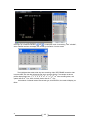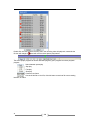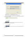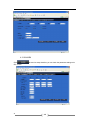
1
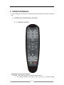
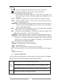
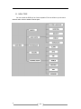
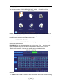
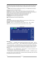
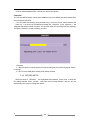
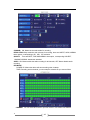
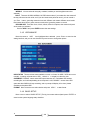
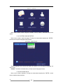
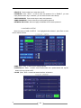
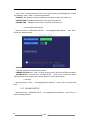
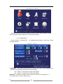
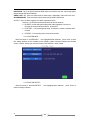
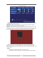
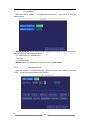
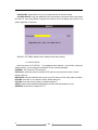
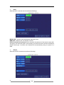
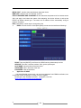
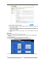
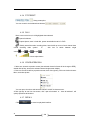
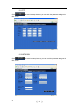
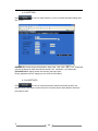
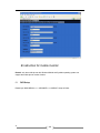
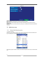
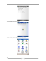
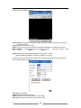
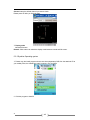
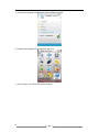
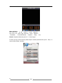
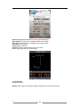
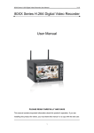
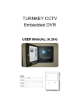
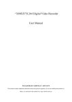
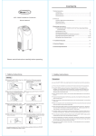
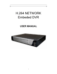
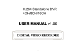
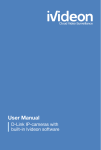
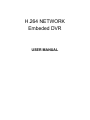
H.264 NETWORK Embeded DVR USER MANUAL CONTENT 1 APPEARANCE……………………………………………………………………………….3 1.1 FRONT PANEL………………………………………………………………………………...3 1.2 REAR PANEL…………………………………………………………………………………..5 2 INTRODUCTION ................................................................................................................... 6 2.0 MAIN FEATURE .............................................................................................................. 6 2.1 PRODUCT FEATURES................................................................................................... 6 2.1.1 PARAMETER.......................................................................................................6 2.1.2 BASIC WORKING PARAMETER ........................................................................8 2.1.3 ENTIRONMENT ADAPTABILITY ........................................................................8 3 OPERATION MANUAL ......................................................................................................... 9 3.1 REMOTE KEY INSTRUCTION OPTIONAL ................................................................ 9 3.1.1 REMOTE CONTROL ...........................................................................................9 3.2 MOUSE OPERATION ................................................................................................... 10 3.3 MENU TREE ................................................................................................................. 12 3.4 SYSTEM OPERATION.................................................................................................. 13 3.4.1 START-UP .........................................................................................................13 3.4.2 SYSTEM LOGIN ................................................................................................13 3.4.3 RECORD SEARCH ...........................................................................................14 3.4.4 RECORD SETUP ..............................................................................................16 3.4.5 HDD MANAGE...................................................................................................18 3.4.6 BASIC SETUP ...................................................................................................18 3.4.7 ADVANCE SETUP.............................................................................................22 4 IE OPERATION ................................................................................................................... 34 4.1 FEATURE...................................................................................................................... 34 4.2 USER LOGIN ................................................................................................................ 34 4.3 OPERATION INTERFACE ............................................................................................ 35 4.3.1 LIVE ...................................................................................................................35 4.3.2 PTZ CONTROL..................................................................................................35 4.3.3 ZOOM ................................................................................................................35 4.3.4 PTZ PRESET.....................................................................................................36 4.3.5 PLAY..................................................................................................................36 4.3.6 OTHER OPERATION ........................................................................................36 4.3.7 REPALY.............................................................................................................36 4.3.8 SETUP...............................................................................................................39 4.3.9 RECORD ...........................................................................................................39 4.3.10 ALARM .....................................................................................................40 4.3.11 PTZ...........................................................................................................41 4.3.12 NETWORK ...............................................................................................41 4.3.13 SETTING ..................................................................................................42 4.3.14 HOST INFO ..............................................................................................42 5 INSTRUCTION FOR MOBILE MONTITOR………………………….…….…………… 43 5.1 DVR SETUP………………..…….…………………………………………………....43 5.2 MOBILE PHONE SETUP……………………………….…………………………….44 5.2.1 WINDOWS MOBILE OPERATING SYSTEM………………………………………44 5.2.2 SYMBIAN OPERATING SYSTEM…………………………………………………..47 2 42 1 Appearance 1.1 Front panel In order to prolong the using life LCD, please close when not in use 3 43 REC/STOP ESC PLAY FRAME NEXT BACK FAST POWER Connect the power supply when DVR REC When the state of video display DVR ALARM When the alarm showed DVR 100M Network than 100M shows LINK Internet connection Enter the system menu Enter PTZ control mode Cancellation of users Convert image REC/STOP function Exit button Play video files Frame put Next section Quick back Quick playback ▲.▼.W. X The direction key POWER The power switch LIGHT MENU PTZ LOAD 4 44 1.2 5 Rear panel ○1 ○3 ○5 Power ○7 Alarm out ○8 RS485 ○9 RS232 1○0 Network 1○1 VGA 1○2 Audio out 1○3 Audio in 1○4 Power switch 1○5 Fan Mouse Video in ○2 ○4 ○6 45 USB2.0 Video out Alarm in Note:road for four road alarm input DVR and alarm input 5-8 no effect 2 INTRODUCTION 2.0 MAIN FEATURE Local recording, playback, support trible code remote network surveillance, data backup, parameter setting, motion detection, I/O alarm setting,PTZ and USB mouse. 2.1 PRODUCT FEATURES H.264 compression Two USB interface, USB2.0 for data backup, USB1.1 for mouse operation. 3.5” SATA HDD. Special file system for secureity. 16 nature translucence GUI, note for menu selected optimized four channel simultaneously playback, (8ch just support one channel playback) double level user management Support the live view, parameter setting and copy playback video via network. 2.1.1 Item System PARAMETER Device performance index Language Chinese/English GUI Graphic menu password user password, administrator password Video in Video Audio Picture proceeding 6 Video out 4CH complex video input 1.0Vp-p impedance75Ω BNC 2CH complex video output 1.0Vp-p impedance75Ω BNC Video display 1/4channel switch/8ch 1/4/9 switch Video standard PAL 25f/s CCIR 625line 50scene NTSC 30f/s CCIR 525line 60scene Audio input 4CH audio input impedance600Ω RCA Audio output 1CH audio output impedance600Ω RCA Basic electricity output Linearity electricity Record style Audio video recorded simultanously Audio compression Picture compression ADPCM H.264 46 and store Picture resolution CIF/HD1/D1(8CH Device only CIF) Streaming style ISO14496-10 Audio style ADPCM Video code rate CIF: 384~768 Kbps HD1: 512~1024 Kbps D1 512~1024 Kbps Audio code rate 32KB/s Data storage Alarm Connector USB 4 alarm input Alarm output 1 alarm output Servial interface Support 1 RS232 Servial interface Support 1 RS485 Network interface RJ45 10M/100M Udisk VGA Software PC playback ohters USB1.1 Mouse VGA Software upgrade 7 Alarm input USB2.0 1 VGA select Playback video file Support USB,network firmware upgrade Voltage input from Voltage output for DVR Voltage output Power Working tempreture AC:110~240V DC 19V@3A +12V@1A(8CH Device w/o output) 6W without HDD -10----60 47 2.1.2 BASIC WORKING PARAMETER item parameter remark Voltage input 19V DC 19V@3A. Voltage outputfor camera Video input impedance Video output I/O 12V +/-0.2V 12V@1A. 75Ω 75Ω each channel. 1Vp-p 1Vp-p CVBS signal 0—2V Low voltage alarm 5V-30v Hight voltage alarm RS232 serial port, for extend use RS485 Connect to PTZ, (Pelco-D Pelco-P) SATA HDD One SATA with all capability 2.1.3 ENTIRONMENT ADAPTABILITY For the saftly using DVR and prolong device life, please pay attention on following detail 1) When installing device, please comply all the electric product safty criterion 2) Power and ground Do not touch the power and DVR with a wet hand Do not drop liquid on DVR Do not put others on DVR Please using soft dry cloth when clean DVR, do not using chymistimpregnant When the power line connects with jack, even don’t startup device. There is still have voltage If you do not use device for long time, please take the power line away from jack. 8 48 3 OPERATION MANUAL In device operation, the enter key on remote control has the same function with mouse left click. 3.1 REMOTE KEY INSTRUCTION OPTIONAL 3.1.1 REMOTE CONTROL Handheld IR Controller Key Functions: 0 9 keys During setup, number keys are used to input values. For viewing channels 1,2,3 and 4, use 1,2,3 and 4 on numeric keypad 9 49 respectively. ▲ Up, Down directional keys: Move selection up and down in setup menu. Left, Right directional keys: Move cusor left or right in setup menu. Enter key: During setup, select and save entry During Playback and preview, displays the channel name, text number, driver name, event sensor item and time, year/month/date, time, GPRS/GPS info. on the screen. PLAY Starts/Resumes playback from any other mode (FF, RR, Frame by Frame etc) Reduces playback speed to SLOW 1/2X 1/4X 1/8X 1/16X mode. Press PLAY to return to normal playback speed. PAUSE/STEP Freezes playback to single frame and can advance one frame at a time. To advance the frame press Pause/Step to move frame by frame. Press EXIT to return to normal playback speed. Fast forward the video while playback.X1, X2, X3, X4 modes available. PressFWD FWD : to switch, press PLAY to return to normal speed REV : Reverse the video while playback, 1X,2X,3X,4X four modes are available. Press REW to switch, press PLAY to return to normal speed POWER ON : Reset the MDVR to Power on and Power off mode. (standby and start up) LOGIN/LOCK : If the security is enabled in the setup, use LOGIN/LOCK key to enter the user setup. It is important to remember the password due to without restoration function. Log in to enter into “User ID select” and “Password” input interface and lock functions To exit setup and operation EXIT : Exit to the preview or return to the last menu RECORD Start manual record——must in manual mode STOP Stop manual record SETUP Enter into setup interface and setup the system parameters PTZ PTZ control press this key to enter into PTZ control interface when at single live view EXTRA For future use . 3.2 MOUSE OPERATION You can use mouse to make operation of the menu except IR remote controller. (The operation usage is the same as PC Windows).Please inserts the mouse into USB1.1. Enter into main menu: Click the right key on the live view. Click right key Exit the present menu: It won’t save the settings if you click the right key to exit. Exit the playback interface: Click the right key to exit when you are playback. Click left key 10 Click the left key to enter into the setting interface. 410 Click the left key to zoom in the window on the live view and playback video. Double click the left key can exit to the live view and playback multi-window interface. 1. Volume adjustment, color adjustment, PTZ setting and VGA border operation.It is for setting the single channel for volume adjustment, PTZ control and color adjustment.If it is multi-window, please use the left key to select the single window. 2. The remark when click the left key for volume adjustment,color adjustment,VGA border is as follow: and on the PTZ setting to adjust parameter, click it can make a. There is the setting for PTZ. b. There is a sticker to show the volume on the volume adjustment interface.Move the mouse to the corresponding position and click the left key,The right side of sticker will show the volume ,click “x”to exit; c. Color adjustment and VGA border operation can refer to the volume adjustment interface operation. When there are many options in the option frame,click left key to ball out down-pull menu. To click the left key on the playback interface can make >> means forward, << means rew, >>I means Slow play, I> means frame play,> means Play, X means exit. Click left 1. In the input frame, click the left key can activate the keyboard. The number, symbol, english can be input by clicking the mouse left. 2. Pingyin also can be input by the softkeyboard when enter Chinese, the method is the same as IR remote controller.You can use the left key to turn over the page when check on Pingyin/Chinese word. 3. When input number, use the left key to select the corresponding value.Also click the left key to exit the number keyboard. Mouse move 1. Press the left key to move the mouse can adjust the parameter on the volume, color.And the corresponding parameter will be display at the same time. 2. In the Motion Detection setting interface, you can use the left key to drag the frame to set the motion detection area. 11 411 3.3 MENU TREE You can control the DVR by a lot of menu operation.This tree will show you the menu structure and it will be in details in after chapter. 12 412 3.4 SYSTEM OPERATION 3.4.1 START-UP Connect the DC19V/3A adapter to DVR. When start up the DVR, POW LED will be on and 4 images will be display on the screen. If it has setup ignition recording or time recording, the system will record automatically and the corresponding LED will be on, the system work normally. Remark: If there is no HDD in device, or device didn’t read the HDD, it will display an H in live view. 3.4.2 SYSTEM LOGIN When you login, you will find the window as follow if the password is enabled, Input device ID and user password via numeric key-board, and you access to main menu via press Apply Remark: default device ID is: 00000, and the password is :user password is oooooo and Admin password is 020818, in order to manage the device more convenience, please setup the user password and change the device ID in the base setup. You can setup user and admin password, Administrator has all authorities, operator has limited authorities who they can only watch, playback, please change the unit ID and default password in time for system security. Unit ID: You just need to enter the unit ID as the right frame. Password: enter the admin password or user password. 13 413 GUI OPERATION The main menu include “SEARCH”,”RECORD”,”HDD”,”BASIC” “ADVANCE”,and“Exit”. Remark: You must after pressing “APPLY”to make the setting for submenu valid.It will no use when exit directly.This DVR have a special feature is: when you move the mouse to everwhere, there will have the explanation information showed autoly. 3.4.3 RECORD SEARCH Move the cursor to RECORD SEARCH Icon highlighted when selected ,press Enter to enter into the setting interface. RECORD FILE:You can adjust the checking date and time,press Enter input the number directly to adjust the year,month,date.After finishing the time setting,move the cursor to “SEARCH” and press”APPLY”,can see the recording status of this date.As follow: Intruction: 1. MONTH: It will show all the recording status in this month. Green means normal recording, 14 414 Red means alarm recording, Grounding means no recording. Click any date in this frame can search the recording status of that day,the searching result will be showed in the below date frame. 2. DATE: It will show all the recording status in this day, you can playback the record file in this period via click the corresponding period. PLYBACK:You can press Enter input number directly to setup playback time.After setting,move the cursor to “PLAYBACK”, and then press”APLLY”to enter into video playback of that time.Also you can select any period of time in the video status frame after searching,press”APLLY”to enter into the video playback of this period. FILE LIST: Enter into the video file list interface of the selected date. LOG SEARCH: Enter into the log seaching interface. EXIT: Exit”video search” to back to the previous menu. 1. FILE LIST Setup the searching date, after pressing “SERACH”,move the cursor to “FILE LIST” and press”APPLY”to enter into the video file list of this date. CHANNEL: There is 1,2,3,4 and all channel, totally 5 options. Press Enter to select. TYPE: There are all,normal and alarm,totally 3 options.Press Enter to select. Instruction 1. FILE LIST “CHANNEL”is the recording file which belong to which channel, “SIZE” is display the size of this file Unit MB “TYPE” is display the type of recording file there are two types: normal and alarm press“BACKUP”button can export the selected files to USB storage 2. After moving the cursor up and down and select the files, and press APPLY to enter into playback interface If the all channels have recording files, it will playback all windows at the same time 3. If setup as “on” in the RECORD TIME in BASIC SETUP it will show the date/time when playback record file If setup as “off”it will not display time 4. When playback can press SLOW to play slowly press FORWARD REVERSE to speed reverse play also can press PAUSE/STEP to pause and frame by frame play Press Exit to exit from playback and return to the former menu 15 415 5. When finished playback files, it will return to the file list interface. 2. BACKUP You can use USB for backup should insert USB device into the USB2.0 port before backup files. And it is support USB OTG. You can select the recording file by direction keys , and press Enter means selected OK There is a “√” at the end of the selected recording files and press Enter again the “√” will disappear that means cancel the select, we can start export the recording files after selecting, and press BACKUP to start to backup, as follow: Instruction 1 When the space in backup device less than recording file, the system will prompt “Space no enough”. 2 You can move USB device directly when backup finished 3.4.4 RECORD SETUP Move the cursor to RECORD Icon highlighted when selected ,press Enter to enter into the setting interface. Press Confirm and enter into the setup interface, and you can use direction keys and cursor to change the options. 16 416 CHANNEL ON: Means the channel enable for recording. RESOLUTION Setup resolution and code rate for recording, there are HIGEST, HIGH, NORMAL three options, corresponding to D1 HD1 CIF resolution. QUALITY There are BEST, FINE ANDNORMAL three option, corresponding HIGHEST, HINGAND NORMAL data stream standard AUDIO ON: Means enable the audio recording for all channels, OFF: Means disable audio recording REC.MODE POWER UP: Means the device will start recording when it startup. TIME: Recording as the schedule, you can setup the schedule as you want as follow. CHANNEL You can select all channel or just one channel blue means has selected 17 417 WEEKLY You can select all everyday, weekend, workday or each day(blue means has selected) DAILY There are ALARM, NORMAL, NO REC three modes, if you select this, that means all the day will record as this mode, and if you don’t want some period to record, you can cancel it via Enter button, grounding means don’t record, different color means different record mode: Red means alarm record, green means normal record, grounding means no record. RECORD SIZE There are 15min, 30min, 45min, 60min four options, that means it will pack as the mode you selected Scroll to APPLY and press ENTER to save the new settings. 3.4.5 HDD MANAGE Move the cursor to HDD Icon highlighted when selected ,press Enter to enter into the setting interface, and you can use direction keys and cursor to change the options. HDD STATUS There are three status available, normal, un-format, No HDD. If HDD can not run normally including unformat and no HDD , there is a H display on video live view. OVERWRITE ENABLE: means when HDD space less than 4G, it will delete HDD earliest recording file, and it will stop deleting when the space is 10G; DISABLE means when HDD space less than 500M it will stop recording, and an prompt will display in live view “please shutdown and replace HDD” FORMAT Move cursor there to select device and press APLLY to start format 3.4.6 BASIC SETUP Move cursor to select “BASIC SETUP” (The big icon means select ok)and press ENTER to enter into the system language setup interface. 18 418 Basic setup includes system language, time/date, security, display, video/audio and exit six options. 3.4.6.1 SYSTEM LANGUAGE SETUP Move cursor to select “system language” (The big icon means select ok)and press ENTER to enter into the system language setup interface. System language have Chinese and English two options, you can setup the language you want in here. Remark: The device will restart when you setup system language success. 3.4.6.2 DATA/TIME SETUP Move cursor to select “date/time” (The big icon means select ok)and press ENTER to enter into the date/time setup interface. 19 419 DATE: Setup system date via numeric key. DATE FORMAT: Press ENTER to switch between the date patterns, there are YY-MM-DD and MM/DD/YY two options. TIME: Setup system time via numeric key. TIME FORMAT: Press ENTER to switch between the date patterns, there are 12 HOURS and 24 HOURS two options. Remark: You must move the cursor to the MODIFY TIME AND DATE and press APPLY to save it, otherwise it won’t save the modify if you exit this interface. DST: haven’t finished yet. 3.4.6.3 PASSWORD Move the cursor to PASSWORD the setting interface. 20 Icon highlighted when selected , press Enter to enter into 420 DEVICE ID Press number key to setup the unite ID PASSWORD Press APPLY to start or close user password. If it is “ENABLE”, you must input password when log in, otherwise, you can enter into main manu directly. USER PASSWORD Press numbe keys to setup user password. ADMIN PASSWORD Press number keys to setup admin password. NETWORK PW CLEAN select and apply will initialize the IE browser password . 3.4.6.4 DISPLAY SETUP Move the cursor to DISPLAY SETUP into the setting interface. Icon highlighted when selected , press Enter to enter NAME: press Enter to enter into the setting interface. POSITION:press Enter to switch name location,there are 5 options:bottom left, top left, bottom right, top right and OFF. COLOR press Enter to enter into setting interface, as following: 21 421 Press Enter or directly drag the cursor to set colors,including chroma,brightness, contrast and saturation, press APPLY to save the parameters. PREVIEW ON: Means the channel is allowed to view the live mode, OFF means not. PREVIEW TIME: ON: Means insert clock in live view, OFF means not. RECORD TIME ON: Means insert clock in record file, OFF means not. 3.4.6.5 VIDOE/AUDIO SETUP Move the cursor to VIDEO/AUDIO SETUP to enter into setting interface. Icon highlighted when selected press Enter VGA RESOLUTION press Enter key to setup the VGA resolution, there are 1024*768 800*600 and 600*480 three options. CAMERA SYSTEM: press Enter to switch camera system, has PAL and NTSC two options VOLUME SETUP move cursor to VOLUME SETUP press Enter to enter into volume setup interface, press number keys or directly drag the cursor to adjust volume. 3.4.6.6 EXIT Move the cursor to EXIT menu. Icon highlighted when selected press Enter to back to main 3.4.7 ADVANCE SETUP Move the cursor to ADVANCE SETUP enter into setting interface. 22 Icon highlighted when selected 422 press Enter to Advanced Features include Alarm settings, system information, Motion detection, mobile phone monitoring, system maintenance, PTZ and network setting. 3.4.7.1 ALARM SETUP Move the cursor to ALARM SETUP into setting interface. Icon highlighted when selected press Enter to enter I/O CHANNEL Each channel corresponds an I/O status, that is, when an alarm triggered, it will activate the corresponding channel to start alarm recording. N.O indicate I / O input level from high to low effective N.C indicate I / O input level from low to high effective HDD LOSS ON means it will trigger a alarm if there is no HDD, and it will display an H On the bottom left of channel 1 in the live view 23 423 HDD SPACE ON If the space less than 500M, there is a remark in live view No enough space, please change HDD after shutdown. VIDEO LOSS ON when one channel has no video input, it will display “video loss”in live view. ALARM MANAGE There are alarm output, buzzer and post REC three items. OUTPUT when an alarm triggered, the alarm output time will be: 0 second 10 seconds,20 seconds,40 seconds and 60 seconds ● BUZZER buzzer calling time setup when alarm triggered: 0 second,10 seconds,20 seconds,40 seconds and 60 seconds ● POST REC. post recording time setup: 30 seconds,1 minute,2 minutes and 5 minutes ● PRE REC Pre-recording time is fixed as10 seconds. 3.4.7.2 SYSTEM INFO Move the cursor to SYSTEM INFO Icon highlighted when selected press Enter to enter into setting interface, at this interface mainly display system hardware features and firmware version, include : device type, firmware version, MAC address serial number. 3.4.7.3 MOTION DETECT Move the cursor to MOTION DETECT enter into setting interface. 24 Icon highlighted when selected 424 press Enter to STATUS Each channel has corresponding channel switch, press Enter to turn on or turn off the motion detection for each channel.. SNESITIVITY each channel has corresponding sensitivity setting,including four standards high,higher,medium and low, press Enter key to switch MD AREA each channel has corresponding regional motion detecting setting,move the cursor to corresponding setting press Enter to enter regional setting interface, red area means it have activated motion detection, transparent block means it have not activated motion detection. Move the direction key on romote control to make cursor move in the small pane, green frame means the cursor has moved to this pane, press Enter to select or cancel motion detection of this small pane, when setup finished, press exit to back to MD setup interface, it will save automaticly. Remark: IR Operation: press [Menu] key to select or cance all the screen. Mouse operation: click left and drag the frame to setup the region for motion detection. 25 425 3.4.7.4 MOBILE Move the cursor to MOBLE setting interface. Icon highlighted when selected press Enter to enter into MOBLE NETWORK: Select different mobile network from the options of 3G, 2.5G and 2.75G, and press [Enter] to switch different network. 3G CDMA1X/EV-DO,WCDMA/HSPA; 2.5G:GPRS 2.75G:CDMA,EDGE MOBLE PORT must different form local network port,( 000000-999999) 3.4.7.5 SYSTEM MAINTAIN Move the cursor to SYSTEM MAINTAIN (Frame turns red means selected), and press Enter to enter into system maintain setup interface. 26 426 AUTO RESET: When switch is on, you can setup the time for device to restart. SYSTEM UPDATE: Copy the update file to the root directory of the thumb driver, and insert it into USB 1.0, then press [Enter] to upgrade the firmware, and it will display the process of the system upgrading, as following: DEFAULT SETTINGS: Restore all the settings as the factory setting. 3.4.7.6 PTZ SETUP Move the cursor to PTZ SETUP Icon highlighted when selected press Enter to enter into setting interface, you can setup the parameters for each channel separately. CHANNEL: The channel of PTZ connected. PROTOCOL: select the protocol of different PTZ, there are two protocols to switch, and the default is Pelco-D BAUD RATE: select the different baud rate for your PTZ, there are 1200, 2400, 4800, and 9600 DATA BIT: there are 5,6,7,8 options to select, default setting is 8. STOP BIT: there are 1and 2 to select, the default setting is 1. VERIFY: there are None/Odd/Even/Mark/Space to select, the default setting is none. ADDRESS: Fill the code of respective PTZ 27 427 3.4.7.7 NETWORK SETUP Move the cursor to [NETWORK SETUP] (Icon thighlitend when selected), and press to enter into setting interface . TYPE: There are PPPOE, DHCP & Static three options. ● STATIC Select [Static] in the type, and press [Enter] to enter into the interface as followings MEDIA PORT transfers video data between client and device. WEB PORT: setup the port of IE browser via HTTP. 28 428 Enter IP ADDRESS: setup the IP address, and press [Enter] number keys to change the value. NETMASK: press [Enter], number keys to change the value. GATEWAY: press [Enter], number keys to change the value. 29 429 ● DHCP Select the DHCP, and enter into the interface as followings. MEDIA PORT transfers video data between client and device. WEB PORT: setup the port of IE browser via HTTP. PPPOE username and password: fill the username and password of the internet service offer, and apply it and reboot the system. After rebooting, the device will save it and set the PPPOE as default network type. If succeed, the IP address will be automatically config as dynamic IP of WAN. ● PPPOE Select the PPPOE, and enter the interface as followings 30 430 MEDIA PORT transfers video data between client and device. WEB PORT: setup the port of IE browser via HTTP. PPPOE USERNAME AND PASSWORD: fill the username and password of the internet service offer, and apply it and reboot the system. After rebooting, the device will save it and set the PPPOE as default network type. If succeed, the IP address will be automatically config as dynamic IP of WAN. DNS: press [Enter], number keys to change the value. ● DDNS: move the cursor to it and press [Enter] to enter into the interface as followings. DDNS: There are [ON/OFF], and if there is a DDNS service, please setup it as ON. SERVICE: There are 3 services to select, 3322, dyndns, perfecteyes. HOST NAME: Input the name of the host server. USERNAME: Input in the name of the user. PASSWORD: Input the password. ● Application of DDNS You should Register a host name, user name and password from DDNS manufacture, now we are take dyndns for example, to show you how to register. Please type in the IE address as follow: to Register a new user. (https://www.dyndns.com/account/create.html). 31 431 1) Fill out all the information then submit. 2) Minutes later, you will get a mail from dyndns, which include the primary password for the user you just register. 3) Then please login http://www.dyndns.com/ with the new user and password, click “domain name management” to enter into the operating interface, then select “new” under the Dynamic DDNS. 4) Create a mane you need, then press apply; now you have Registered a host name success. An example: Network: ADSL, only one DVR need to connect to internet. 1) Make sure the DVR has connected to ADSL modem success; the LED is flashing means success. 2) Network type: PPPoE 3) Input media port and web port, default value is 9000 and 0080 4) Type in the PPPoE user name and password from internet manufacture. Fill in the IP of DNS sever, such as 202.96.128.166 5) 32 Since the public IP will change after restart, please use DDNS function, and mapping the 432 public IP to a fixed domain name, as the picture. Save and restart device, it will connect to internet via PPPoE mode automatically, if success, it will got a dynamic public IP. 7) ping xxx.xxx.xxx.xxx(The public IP of DVR) to check whether the network is ok, and ping xxx.xxx.xxx the domain name of DVR to check whether the DDNS settings is ok. 8) Open IE browser, and type in the domain name of DDNS (if WEB port is not 80, you should add a port, such as:http://members.dydns.com:8088 ) Please download the IE control, then enter into login interface, the default setting has no password. 6) 33 433 4 IE OPERATION 4.1 FEATURE Through the IE browser of OS and install the software, you are able to do the network operation remotely, which is much more convenient. DVR support C/S, B/S, and visit in LAN and WAN, also support IP and domain name visiting. 4.2 USER LOGIN Input the DVR local IP in IE browser, when changed the port, you should add the port number after IP address, e.g. if DVR local IP is 192.168.3.97 (LAN) and the port is 8088, you should input http:// 192.168.3.97:8088. The default port is 8088, and directly input http:// 192.168.3.97 to access the login interface as following, Select English interface in the top left side. Input username and password to enter into the system. The username and passport is same as the ones set in DVR. PASSWORD: Administrator has all authorities, operator has limited authorities who they can only watch, playback, please change the unit No. and default password in time for system security. NETWORK: LAN/WAN Remark: If you connect the device in WAN, the IP should be a public IP. 34 434 4.3 OPERATION INTERFACE There are Liveview, Playback and Setup options in the main interface, please press them to access it. 4.3.1 LIVE Click to enter into the interface as followings 4.3.2 PTZ CONTROL Change the focus, preset aperture to control the PTZ. to up/down/left/right control movement of the PTZ. When Click hold on the one direction key, the PTZ will keep circling as that direction after user press the stop key in the center of the wheel. 4.3.3 ZOOM Click to zoom in and out. Click to focus Click 35 to change the size of aperture 435 4.3.4 PTZ PRESET Setup preset point. You can control it via the below three buttons: 4.3.5 PLAY Move cursor to the icons, it will highlighted when selected Open all windows. Capture picture, save in local disk, system save default route is C:/DVR normal screen Quickly start all channels’ recording video, here the left up corner of each channel have recording video symbol R , click icon to switch between singal /quad /nine /16 spllit . Volumn adjust button 4.3.6 OTHER OPERATION 1. Select one channel at preview screen (the selected channel’s frame will be change to RED), double click left key, enter to the selected channel single screen display. 2. Click one Chanel via left key at preview screen, then click right key, will occur window shortcut Menu, see below picture You can open, shut down and start this channel’s record via shortcut menu. 3.Click right key at one live view screen, click” open all windows” or “ close all windows”, will quickly open/close all windows. 4.3.7 REPALY Click 36 to enter into playback interface. 436 and , to setup the month for searching, click” refurbish”, Click right up of calendar interface at the calendar interface will display the recording information of current month The highlighted date means that day have recording video, RED FRAME means the date is system date, click the date will search that days’ recording file list. For example, the above picture display 2008, Dec. 3rd,4th,5th,6th,8th,9th,10th,11th,12th,17th,18th have recording video, and system date is 18th, Dec, 2008, currently search date is 17th, Dec. At the below of calendar select channel and type, click SEARCH, the result will display, as follow. 37 437 Double click one item of listed recording video, the recording video will playback, meanwhile the file icon will change to , and will occur the below picture play buttons: The above purple progress bar shows download progress, green progress bar shows playback progress Switch between pause/play Stop play Fast play Slow play Pause at next frame Convert H.264 file to H.avi file, click this button access into file convert setting interface, as follow. 38 438 SOURCE FILE: Click DESTINATION FILE: Click After setting, click will see the progress of convert. to setup the H.264 file to convert to setup the directory for saving avi file , file convert start, the convert progress bar (see below picture) 4.3.8 SETUP Click to enter into setup interface, this interface include record, alarm, PTZ, network, setting and system information six menus. 4.3.9 RECORD Click GUI of DVR. 39 to enter into setup interface; you can check the parameter settings as in 439 4.3.10 ALARM Click GUI of DVR. 40 to enter into setup interface; you can check the parameter settings as in 440 4.3.11 PTZ Click GUI of DVR. to enter into setup interface; you can check the parameter settings as in 4.3.12 NETWORK Click GUI of DVR. 41 to enter into setup interface; you can check the parameter settings as in 441 4.3.13 SETTING Click GUI of DVR. to enter into setup interface; you can check the parameter settings as in BANDWIDTH: Set the amount of bandwidth in kbps (128k 192k 256k 384k 512k 1024k) that you want to allocate for traffic that matches internet this bandwidth not include audio . FILE SAVE PATH: capture picture and recording video save path. IE login password and DST settings you can check as DVR setting. 4.3.14 HOST INFO Click to enter into system information interface (see below picture), this interface shows HDD status, remain record time, firmware version, MAC Address, and all the information is fixed. 42 442 5 Instruction for mobile monitor Remark: only the mobile phone with Windows Mobile and Symbian operating system can support the mobile phone monitor function. 5.1 DVR Setup Please login MAIN MENU>>>>> ADVANCE>>>>>MOBILE, setup as follow: 43 443 Channel: Please select the channel for wireless transmission. Mobile Network: Please select the network your SIM card support. Mobile port: this port should be open in the router; otherwise you can’t see the live view in mobile phone. Remark: this port can’t be the same with any other port, and different DVR should have different sever port. 5.2 5.2.1 Mobile phone setup Windows Mobile Operating system 1 Program download Please copy the installation program whose name is amplayersetup.CAB from the attached CD to your mobile phone, the default save path is My Documents. 2 Click the program and start to install it, just select default path when it ask you to select install path. 44 444 3 Click install button to start to install. 4 After installed, click the QQeye icon to run the program. 45 445 5 login the main interface as follow. Channel: select the channel you want to monitor. When you select a channel, it will connect to DVR automatically. Connect: press it to connect to DVR. Setup: Press it to enter into the interface to config the parameters for mobile phone monitor. Button definition PTZ direction control left right up down ; area select zoom in zoom out ; focus ; aperture ; snapshot . Remark: Please make sure the parameters for PTZ in DVR is correct. Snapshot default save path is: Program>>>QQeye>>>> photo 6 When you login for the first time, please setup the network parameters first, press setup to enter into the interface, as follow: User name: can be blank. Password: should be the same as IE. Sever: the public IP or dynamoic domain name of DVR. Sever port: this port is the mobile port you setup in DVR. 46 446 Channel: setup the default channel you want to check. Please press OK after you finished setup. 7 Display mode Normal/Full screen Remark: Click screen can switch the display mode between normal and full screen. 5.2.2 Symbian Operating system 1 Please copy the install program whose name is amplayersetup.CAB from the attached CD to your mobile phone, the default save path is memory card. As follow: 2 Click the program to install it. 47 447 3 You can select the install path you want as the follow picture . 4 Please select continue when you got the follow window, and make sure your mobile phone can access to internet. 48 448 5 you will got a message “install finished” after installed successful. 6 Please find the QQeye icon in Application and run it. 7 when you login, you will find the window as follow: 49 449 Button definition CH1 CH2 PTZ up left zoom in + focus + aperture + CH3 CH4 PTZ down right zoom out – focus – aperture – Play/Pause Full screen/Normal Snapshot Setup Exit Remark: Snapshot default save path is: "C \Data\Images\” 8 When you login for the first time, please setup the network parameters first, press enter into the interface, as follow: 50 450 Setup to Net Access point: Please select the network, GPRS/EDGE/3G Sever address: the public IP or dynamic domain name of DVR. Sever port: the sever port is the mobile port you setup in DVR. User name: can be blank. Password: the same as IE. Channel: setup the default channel you want to check. Please press Apply after you finished setup. 9 Display mode Normal/ Full screen Remark: Click screen can switch the display mode between normal and full screen. 51 451