1
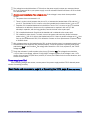
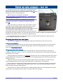
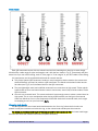
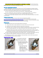
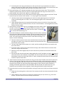
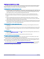
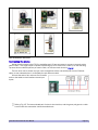
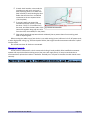
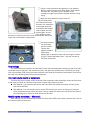
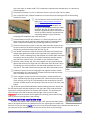
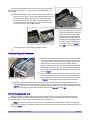
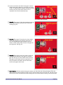
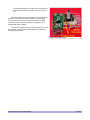
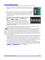
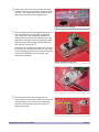
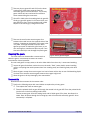
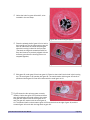
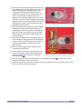
Notice the holes for gears #1 and #2, to be installed in the next steps. 64: Gears #3 and #4 snapped installed.together. Fig. 63: Place the pointed shaft of gear #1 in its hole in the housing top. The the long teeth on gear #1 with will mesh with the motor armature gear when the housing is closed in the final step. (The teeth are long and somewhat flexible so they don't have to be precisely aligned with the armature gear when the housing halves are snapped together.) Fig. 65: Gear #1 installed. Slide gear #2 under gear #3 and over gear #1. Place its short shaft into its hole in the housing top. The small gear on #2 meshes with gear #3. The metal retainer disk on gear #2's shaft is positioned above gear #3. Gear #2 meshes with the small gear on #1. Fig. 65 shows the four primary gears correctly installed. Notice how gear #3 is positioned above gear #2 and below the metal retainer. Also notice how gear #3 meshes with the small gear on #2, and how gear #2 meshes with the small gear on #1. The pointed shaft on the armature gear will fit into the hole to the right of gear #1, and the armature gear will mesh with the long teeth on gear #1. FCC4 Fast Clock Controller User Manual Page 56