1
TD 92586GB
Installation and Operation Manual
IMS2
10 January 2011 / Ver. E
Installation and Operation Manual
IMS2
TD 92586GB
Contents
1 Introduction .................................................................................................................... 1
1.1 Licenses for IMS2...................................................................................................................... 2
1.2 Abbreviations and Glossary................................................................................................... 3
1.3 Overview..................................................................................................................................... 6
1.4 How to Use this Document .................................................................................................... 6
1.5 Included in the delivery .......................................................................................................... 9
1.6 Technical Solution .................................................................................................................... 9
1.7 Requirements ............................................................................................................................ 9
2 Installation and Configuration.................................................................................... 10
2.1 Required information ........................................................................................................... 10
2.2 Mounting ................................................................................................................................. 10
2.3 Hardware Installation and Configuration........................................................................ 10
2.4 Software Installation ............................................................................................................ 10
2.5 IMS2 Setup.............................................................................................................................. 10
2.6 Update of IMS2 ...................................................................................................................... 11
2.7 Multiple IMS2 Configuration............................................................................................... 12
3 Data Backup .................................................................................................................. 20
4 IMS2 General ................................................................................................................. 21
4.1 Authentication Levels and Default Passwords .............................................................. 21
4.2 Functionality matrix ............................................................................................................. 22
4.3 Set passwords ........................................................................................................................ 22
4.4 Password policy ..................................................................................................................... 23
4.5 Web access security settings ............................................................................................. 23
4.6 Configuration Page ............................................................................................................... 24
4.7 Icons.......................................................................................................................................... 25
4.8 Certificates .............................................................................................................................. 26
5 IMS2 Setup Wizard and Configuration ....................................................................... 28
5.1 Basic Configuration Steps ................................................................................................... 28
5.2 Optional Settings................................................................................................................... 29
6 Operation - Messaging ................................................................................................. 30
6.1 Messaging Tool ...................................................................................................................... 30
6.2 NetPage ................................................................................................................................... 30
7 Central Phonebook Administration............................................................................ 32
7.1 Edit the Central Phonebook ................................................................................................ 32
7.2 Import and Export a Central Phonebook ......................................................................... 34
8 Device Manager ............................................................................................................ 36
10 January 2011 / Ver. E
Installation and Operation Manual
IMS2
TD 92586GB
8.1 Description .............................................................................................................................. 36
8.2 Log In........................................................................................................................................ 45
8.3 Close the Device Manager ................................................................................................... 45
8.4 Templates in Device Manager ............................................................................................ 45
8.5 Numbers .................................................................................................................................. 49
8.6 Devices ..................................................................................................................................... 57
8.7 License Restrictions for Device Handling ........................................................................ 62
8.8 Licenses.................................................................................................................................... 66
8.9 File management................................................................................................................... 69
8.10 Import and Export .............................................................................................................. 78
8.11 Other Settings ..................................................................................................................... 80
9 DECT Interface............................................................................................................... 83
9.1 Cordless Telephone System ................................................................................................ 83
9.2 DECT Interface Settings ....................................................................................................... 84
10 WLAN Interface .......................................................................................................... 87
10.1 Handset Registration......................................................................................................... 87
10.2 Shared Phones..................................................................................................................... 87
10.3 WLAN Message Distribution ............................................................................................ 87
10.4 WLAN System...................................................................................................................... 88
10.5 User Server ........................................................................................................................... 89
10.6 Handset Administration.................................................................................................... 89
11 System 900................................................................................................................. 92
11.1 System 900 Interface........................................................................................................ 92
11.2 System 900 Message Distribution................................................................................. 94
12 Messaging Groups ...................................................................................................... 95
13 Basic Configuration.................................................................................................... 97
13.1 Central Phonebook Configuration .................................................................................. 97
13.2 Alarm Handling ................................................................................................................. 106
13.3 Status .................................................................................................................................. 112
13.4 Input/Output Setup ......................................................................................................... 115
13.5 Backup the Configuration............................................................................................... 118
13.6 Restore the Configuration .............................................................................................. 118
13.7 Device Configuration........................................................................................................ 120
13.8 Coloured messaging......................................................................................................... 121
13.9 Additional System Settings ........................................................................................... 122
14 Remote Management .............................................................................................. 128
15 Absence Handling .................................................................................................... 130
15.1 Absence Handling in DECT.............................................................................................. 130
15.2 Absence Handling in VoWiFi System ........................................................................... 131
10 January 2011 / Ver. E
Installation and Operation Manual
IMS2
TD 92586GB
16 Base Station Conversion.......................................................................................... 132
16.1 Background ........................................................................................................................ 132
16.2 Configuration ..................................................................................................................... 132
17 Messaging ................................................................................................................. 133
17.1 Messaging Tool Configuration....................................................................................... 133
17.2 NetPage Configuration.................................................................................................... 133
17.3 Predefined Groups............................................................................................................ 135
17.4 Predefined Messages....................................................................................................... 136
17.5 Message History Status .................................................................................................. 137
18 Language and User Interface .................................................................................. 138
18.1 Customize the Language for IMS2 Menus.................................................................. 138
18.2 Customize the User Interface (GUI) ............................................................................. 142
18.3 Password Protected Access to NetPage ..................................................................... 150
18.4 Accessing NetPage from a Cordless Unit with WAP ................................................ 150
18.5 Test the New User Interface........................................................................................... 152
18.6 Update the User Interface after a new IMS2 Release.............................................. 152
19 Serial Interface ......................................................................................................... 153
19.1 Serial Protocol Settings ................................................................................................... 153
20 Open Access Protocol (OAP).................................................................................... 159
20.1 Configuration ..................................................................................................................... 159
21 Troubleshooting ....................................................................................................... 160
21.1 General Troubleshooting ................................................................................................ 160
21.2 Device Manager Troubleshooting................................................................................. 160
21.3 NetPage Troubleshooting............................................................................................... 161
21.4 Troubleshooting Guide .................................................................................................... 161
21.5 Built-in tools in IMS2........................................................................................................ 167
21.6 Advanced Troubleshooting ............................................................................................ 169
21.7 What to consider when replacing a module .............................................................. 170
21.8 Technical Support ............................................................................................................. 170
22 Related Documents.................................................................................................. 171
23 Document History .................................................................................................... 172
Appendix A: Used IP Ports for IMS2 ............................................................................. 174
Appendix B: RJ45 connections ..................................................................................... 175
Appendix C: Alarm Action Configuration Examples ................................................... 176
Appendix D: Protocol Limitations ................................................................................ 184
Appendix E: Device Manager Keyboard Shortcuts ..................................................... 187
Appendix F: Function Indicator and Error Relay Output ............................................ 189
Appendix G: File types................................................................................................... 191
Appendix H: Migration Guide ....................................................................................... 192
Index .............................................................................................................................. 207
10 January 2011 / Ver. E
Installation and Operation Manual
IMS2
10 January 2011 / Ver. E
TD 92586GB
Installation and Operation Manual
IMS2
1
TD 92586GB
Introduction
Integrated Wireless Messaging Services (IMS2) is a web-based tool used for device
management, messaging and alarm handling. It is a module based on ELISE2 hardware,
designed as an all-in-one solution for Centralized Management of portable devices. This
document describes the installation and configuration of IMS2 plus operation of the system.
The main functionality is:
•
•
•
•
•
•
On-site and remote administration of handsets and chargers
Parameter configuration and software download to handsets and chargers
Supervision of chargers
Central phonebook application for handsets
Text messaging between handsets
Alarm Handling
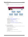
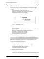
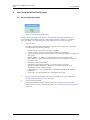
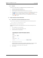
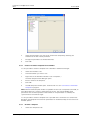
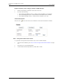
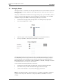
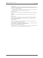
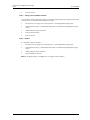
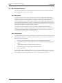
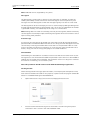
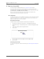
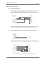
Figure 1 shows the IMS2 in a system.
Figure 1.
DECT
Handsets
WiFi
Handsets
PDM
LAN
Client
301
IMS2
Figure 1. IMS2 in a system.
IMS2 provides a generic application for managing portable devices and chargers in wireless
systems.
IMS2 makes it possible to edit parameters and update software in the devices. It saves
parameters and software for all devices in a database. All devices are updated remotely
from the IMS2.
A serial interface is included to enable pagings from external equipment. The serial interface
supports the ESPA 4.4.4 protocol, the Ascom Line protocol and the TAP 1.8 protocol. The
Ascom Line protocol is designed to be simple enough to be controlled manually, using a
terminal program connected to the serial port.
IMS2 also includes a central phonebook which can be accessed from the handsets. The
number of entries in the phonebook depends on whether the internal database or an
external database is used as phonebook source.
This document is intended as a guide for installation, maintenance and troubleshooting
purposes and is relevant for:
10 January 2011 / Ver. E
1
Installation and Operation Manual
IMS2
•
•
1.1
TD 92586GB
Installation and configuration, administrator rights
Daily operation of the system, user rights
Licenses for IMS2
Basic License for IMS2
•
WSM-MAS, including ELISE2 hardware including ELISE2 hardware.
Additional Licenses for IMS2
• WSM-LAS, as WSM-MAS but without ELISE2
• WSM-LAA, Basic Alarm Manager for message and alarm handling
• WSM-LAN, NetPage functionality
• WSM-LAP1, ESPA 4.4.4, Ascom Line Protocol, URL Messaging Protocol, TAP 1.8
• WSM-LAP2, OAP, Open Access Protocol for sending messages and receiving alarms
• WSM-LAP3, License for OAP protocol with interactive messaging, user data and alarm
• WSM-LAM1, Device Management, 100 devices, 250 numbers
• WSM-LAM2, Device Management, 500 devices, 1 250 numbers
• WSM-LAM3, Device Management, 1 000 devices, 2 500 numbers
• WSM-LAM4, Device Management, 2 500 devices, 6 250 numbers
For details regarding licenses and technical specifications, refer to Data Sheet, IMS2,
TD 92585GB.
IMS2 running as PDM System version
For backward compatibility, IMS2 can replace PDM System Version. Note that in this case it
will only have support for Device Management. It then works with the following licenses:
•
•
•
PDM-LIC, for 100 devices
PDM-LID, for 500 devices
PDM-LIM, for 1 000 devices
10 January 2011 / Ver. E
2
Installation and Operation Manual
IMS2
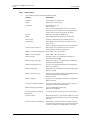
1.2
TD 92586GB
Abbreviations and Glossary
Ascom Line Protocol
A simple alternative to ESPA 4.4.4 with all basic features of
paging call available but with a very limited status report.
BAM
Basic Alarm Manager:
tool in the IMS that can be used to handle triggered inputs
and alarms and user data from handsets.
In IMS2, this tool is referred to as Alarm Handling.
Central Phonebook
A Phonebook stored in a database in the control module or
reached from the control module.
Charger
Can be a desktop charger or a charging rack
Company Phonebook
A Phonebook that is uploaded to a handset from the Device
Manager. The entries are locked for editing in the handset.
Contacts
The name of the phonebook in a handset.
CSV file
Comma Separated Value:
A file with data, where values in each row are separated by a
delimiter, which can be a comma, a semicolon or a tab.
DECT
Digital Enhanced Cordless Telecommunications:
A global standard for cordless telephony.
Device
Can be a DECT or VoWiFi handset, an alarm transmitter, a
pager or a charger developed to work together with IMS2 and
the Device Manager. See the user manual for respective
device.
DHCP
Dynamic Host Configuration Protocol
EAP
Extensible Authentication Protocol
ELISE2
Embedded LInux SErver
A hardware platform used for IMS2.
ESPA 4.4.4
A message-based serial protocol intended for
communication with external equipment. Built upon the
ISO1745 transport specification.
ESS
Ascom Enhanced System Services:
Unite module that handles centralized number planning,
remote connection, system supervision, fault handling, group
handling, message routing, centralised logging, activity
logging, and user access administration.
FTP
File Transfer Protocol
GUI
Graphical User Interface
IMS
Integrated Message Server:
Unite module that enables messaging to and from the
connected cordless telephone system
IMS2
Integrated Wireless Messaging and Services
IPBS
IP-DECT Base Station
IPDI
International Portable DAM Identity
DAM (DECT Authentication Module)
See IPEI for more information.
10 January 2011 / Ver. E
3
Installation and Operation Manual
IMS2
TD 92586GB
IPEI
International Portable Equipment Identity:
IPEI/IPDI is needed to enable network subscription of the
handset. At delivery of the handset, IPEI and IPDI are the same
and either can be used for network subscription. If the IPEI and
the IPDI differ, the IPDI shall be used for network subscription.
JRE
Sun Java Runtime Environment.
LAN
Local Area Network. A group of computers and associated
devices that share a common communication line.
Language file
Language file for portable devices or IMS2.
Language file for IMS2 uses XML (eXtensible Markup
Language.).
LDAP
Lightweight Directory Access Protocol
License file
A file containing license keys for devices. The file can be
exported from the license web and imported to the Device
Manager in the IMS2.
License key/number
The unique license key for a specific device or for IMS2 with a
specific functionality.
Messenger
Product license for Messaging solutions for Ascom handset.
NetPage
Tool for generating messages from a web browser.
Number
Settings for the complete set of parameters of a single device,
tied to a specific identity.
OAP
Open Access Protocol:
Ascom defined XML based messaging and alarm protocol.
OTA
Over the Air
Parameter definition file
Defines the parameters for a portable device model, for
example a handset, alarm transmitter etc.
PKCS#12
A chryptography standard, defining a file format used to store
keys and certificates.
Handset
Cordless handset, alarm transmitters/transceivers etc.
Product information file
A file containing information needed for licensing and
upgrade of a device. The file can be exported from IMS2 and
imported to the License web.
Protector
Ascom name for handsets with alarming capabilities
RTLS
Real Time Location System
Talker
Ascom name for handsets primarily used for pure telephony.
TAP
Telelocator Alphanumeric Protocol:
An industry standard protocol for the input of paging
requests.
Unite system
Unite is the Ascom name for the Ascom Professional
Messaging system.
The Unite communication protocol is used for communication
between IMS2s in systems with more than one IMS2.
UNL
Universal Networking Language
UNS
Unite Name Server:
Unite module component that holds the Unite number plan
and Unite destinations
10 January 2011 / Ver. E
4
Installation and Operation Manual
IMS2
TD 92586GB
VoWiFi
Voice over Wireless Fidelity:
is a wireless version of VoIP and refers to IEEE 802.11a,
802.11b, 802.11g, or 802.11n network.
WiFi
WiFi is a term developed by the Wi-Fi Alliance® to describe
wireless local area network (WLAN) products that are based
on the Institute of Electrical and Electronics Engineers' (IEEE)
802.11 standards. Today, most people use WiFi as a reference
to wireless connectivity.
WLAN
Wireless LAN
10 January 2011 / Ver. E
5
Installation and Operation Manual
IMS2
1.3
TD 92586GB
Overview
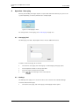
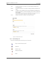
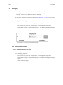
From the IMS2 start page (see Figure 2) it is possible to select different functionality
modules.
2.
Figure
Figure 2. IMS2 start page.
•
•
•
•
•
1.4
Messaging, see 6 Operation - Messaging on page 30.
Phonebook, see 7 Central Phonebook Administration on page 32.
Describes how to handle phonebook entries.
Device Manager, see 8 Device Manager on page 36.
Describes device management.
Configuration, see 4.6 Configuration Page on page 24.
Setup page for the IMS2 settings.
Setup Wizard, see 5 IMS2 Setup Wizard and Configuration on page 28.
The first time and as long as IMS2 is not configured, the setup wizard will start
automatically.
How to Use this Document
This document is used for the installation and configuration of the product, as well as for the
administration and daily operation.
This sub chapter includes the following steps:
• Installation and setup for IMS2
• Extended configuration
• Configuration for IMS2 running as PDM System version
• Phonebook administration
• Daily operation
In order to simplify, for example an installation, use the following description:
10 January 2011 / Ver. E
6
Installation and Operation Manual
IMS2
1.4.1
•
1.4.2
TD 92586GB
Installation and Setup for IMS2
For installation and basic configuration, see the following chapters:
- 2 Installation and Configuration on page 10
- 5 IMS2 Setup Wizard and Configuration on page 28
Extended Configuration
Some extended configuration is included in the basic license, other requires an additional
license, see below:
•
For settings included in the WSM-MAS license:
Refer to chapters:
- 11 System 900 on page 92
- 12 Messaging Groups on page 95
- 13 Basic Configuration on page 97
- 7 Central Phonebook Administration on page 32
- 14 Remote Management on page 128
- 15 Absence Handling on page 130
- 16 Base Station Conversion on page 132
•
For settings included in the WSM-LAA license option:
Refer to chapters:
- 13.2 Alarm Handling on page 106
•
For settings included in the WSM-LAN license option:
Refer to chapters:
- 17 Messaging on page 133
•
For settings included in the WSM-LAP1 license option:
Refer to chapters:
- 18.2.8 Creating a URL Call on page 148
- 19 Serial Interface on page 153
•
For settings included in the WSM-LAP2 license option:
Refer to chapters:
- 20 Open Access Protocol (OAP) on page 159
See also Function Description, Open Access Protocol (OAP), TD 92215GB.
•
For settings included in the WSM-LAP3 license option:
Refer to chapters:
- 20 Open Access Protocol (OAP) on page 159
See also Function Description, Open Access Protocol (OAP), TD 92215GB.
•
For settings included in the WSM-LAM1 license option:
Refer to chapters:
- 8 Device Manager on page 36 (100 devices)
•
For settings included in the WSM-LAM2 license option:
Refer to chapters:
- 8 Device Manager on page 36 (500 devices)
10 January 2011 / Ver. E
7
Installation and Operation Manual
IMS2
•
TD 92586GB
For settings included in the WSM-LAM3 license option:
Refer to chapters:
- 8 Device Manager on page 36 (1 000 devices)
•
For settings included in the WSM-LAM4 license option:
Refer to chapters:
- 8 Device Manager on page 36 (2 500 devices)
A summary of extended configuration can be found in chapter 5.2 Optional Settings on
page 29.
1.4.3
•
1.4.4
Configuration for IMS2 running as PDM System version
For settings included when IMS2 is running as PDM System Version, the following
chapters are valid:
- 2 Installation and Configuration on page 10
- 8 Device Manager on page 36
- 13.5 Backup the Configuration on page 118
- 13.6 Restore the Configuration on page 118
Charger Installation
Follow the instructions in the manual for the charger.
1.4.5
•
1.4.6
•
Central Phonebook administration
For administration of the central phonebook, refer to chapter 7 Central Phonebook
Administration on page 32.
Daily Operation
For the daily operation, that is, creating and sending messages, see chapter 6 Operation Messaging on page 30.
10 January 2011 / Ver. E
8
Installation and Operation Manual
IMS2
1.5
Included in the delivery
•
•
•
•
•
1.6
TD 92586GB
ELISE2 hardware
Power supply 100-240V DC and cables for EU, UK, US and AUS
“Getting started” instructions leaflet
Ordinary RJ45 (straight through pinouts) network cable for connection to the LAN
License certificate
Technical Solution
IMS2 consists of a server and a client part. The server runs on the ELISE2 hardware and is
configured from a web interface. The Java based client is run on a PC connected to the Local
Area Network (LAN) and is loaded from the server (Device Manager).
1.7
Requirements
Refer to Data Sheet, IMS2, TD 92585GB.
10 January 2011 / Ver. E
9
Installation and Operation Manual
IMS2
2
TD 92586GB
Installation and Configuration
After installing the IMS2, the basic configuration is easily done with the help of a setup
wizard. The setup wizard includes all basic settings needed to get the IMS2 up and running.
2.1
Required information
Make sure the following information is available:
2.1.1
•
•
2.1.2
•
•
•
•
•
•
2.2
Information required for the Installation
MAC address – found on the license certificate enclosed in delivery
An IP address is needed, see leaflet or Installation Guide, ELISE2, TD 92232GB.
Information required for the Configuration
License number – found on the license certificate enclosed in delivery
Network parameters – ask your network administrator
Type of connected wireless phone system
IP address to connected system (if connected via IP)
Other messaging systems to send messages to (optional)
LDAP properties if an LDAP server is used for Central Phonebook requests (optional)
Mounting
For mounting, see Installation Guide, ELISE2, TD 92232GB.
2.3
Hardware Installation and Configuration
For installation and configuration, see Installation Guide, ELISE2, TD 92232GB for more
information.
Note: Attach the ferrite bead on the power supply cable. Follow the enclosed assembly card
for EMC protection, M0271500.
2.4
Software Installation
For software installation, see Installation Guide, ELISE2, TD 92232GB for more information.
2.5
IMS2 Setup
When accessing IMS2 the first time, follow the instructions in section Configuration in the
Assembly Card, Getting Started M0276300 (enclosed in delivery), or see Installation Guide,
ELISE2, TD 92232GB.
The setup wizard is described in chapter 5.1 Basic Configuration Steps on page 28.
Note: The IP address must not change during operation because renew of IP address via
DHCP is not handled. Other equipment connected to this product also expects a fixed IP
address in some cases. If the IP plan is changed, this product must be restarted to update
the IP address. Otherwise there is a risk for IP address collision.
For information about Power Down and Restart, see Installation Guide, ELISE2, TD 92232GB.
10 January 2011 / Ver. E
10
Installation and Operation Manual
IMS2
2.6
TD 92586GB
Update of IMS2
Update of software is done via the web interface.
There are two choices, "Install software" and "Install image".
If new software is installed by doing an update of IMS2 using an *.eas file, the information
stored in the database will not be overwritten.
If a new image file is installed, using an *.img file, the database information is deleted, and
software and definition files are removed.
For instructions on how to upgrade, both .eas and .img files, see Installation Guide, ELISE2,
TD 92232GB. It is recommended to do a backup before upgrading.
Make sure that no Device Manager client is open during an update of the IMS2. It is also
important that no ftp client is logged in to the IMS2. If the Microsoft Internet Explorer is
used as ftp client, close it before upgrade.
Note: Customized NetPage GUI will be overwritten when upgrading. See also
18.6 Update the User Interface after a new IMS2 Release on page 152.
10 January 2011 / Ver. E
11
Installation and Operation Manual
IMS2
2.7
TD 92586GB
Multiple IMS2 Configuration
In some situations, it is necessary to configure more than one IMS2 in a system. This chapter
presents examples for multiple IMS2 configuration.
This is required in systems:
•
•
•
•
•
with centralized management for more than 1 000 devices,
see 2.7.1 More than 1 000 devices, all handsets registered on one IMS2 on page 12.
for DECT, with centralized management in combination with a traffic load expected to be
more than 4 000 messages per hour (or an equivalent amount of central phonebook
enquires), see 2.7.2 High messaging load in DECT on page 14.
for WiFi, with centralized management in combination with a traffic load expected to be
more than 4 000 messages per hour (or an equivalent amount of central phonebook
enquires), see 2.7.3 High Messaging load in WiFi on page 16.
with multi-master IP-DECT systems
(one IMS2 per IP-DECT master, in combination with number planning),
see 2.7.4 Multi-master IP-DECT systems and Multiple DECT systems on page 18.
with a multiple DECT system (one IMS2 per DECT system, in combination with number
planning),
see 2.7.4 Multi-master IP-DECT systems and Multiple DECT systems on page 18.
For detailed instructions on how to do these settings, refer to the corresponding chapters in
this manual.
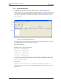
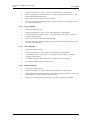
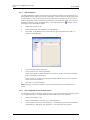
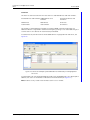
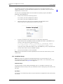
2.7.1
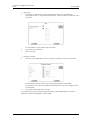
More than 1 000 devices, all handsets registered on one IMS2
On each IMS2 up to 1 000 devices can be configured. If there are more than 1 000 devices
that shall be configured, one possible solution is to use two IMS2 modules and to register
the handsets on one IMS2 and the chargers on another IMS2 (see Figure 3).
Figure 3. Figure 3
IMS2-B
(Chargers)
Device
Manager1
Device
Manager2
Device
Handler1
Device
Handler2
518
IMS2-A
(Handsets)
Figure 3. Example of a multiple IMS2 solution with handsets and chargers registered
on two IMS2s.
10 January 2011 / Ver. E
12
Installation and Operation Manual
IMS2
TD 92586GB
Configuration for the setup
The basic configuration for this setup is described below. In this configuration, only the
IMS2-A module has a DECT connection and the DECT interface in IMS2-B is disabled.
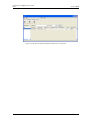
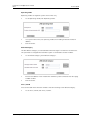
•
IMS2-A
- Set the Device Manager to handle only portable devices:
Configuration > Other Settings > DECT Interface > Device Handling
Portable Devices: Set "Device support" to Enabled
Desktop Chargers: Set "Device support" to Disabled
Rack Chargers: Set "Device support" to Disabled
Figure 4.
Figure 4. Setting handsets on IMS2-A.
•
IMS2-B
- Disable the DECT interface
In Configuration > Other Settings > Advanced Configuration > General Settings > View
advanced parameters:
Set "DECT Interface" to Disabled.
- Set the Device Manager to handle only chargers:
Configuration > Other Settings > DECT Interface > Device Handling
Portable Devices: Set "Device support" to Disabled
Desktop Chargers: Set "Device support" to Enabled
Rack Chargers: Set "Device support" to Enabled
Example: Migration to a double IMS2 solution
This example assumes that the original system has all device management on one IMS2. The
reason for a migration to a double IMS2 solution is that the number of registered devices
will increase to more than 1 000, but the number of handsets is expected to remain under 1
000. The device management of the chargers will be moved to the new IMS2. In this
example, the DECT interface in IMS2-B is disabled.
Change the following settings in the original IMS2:
•
IMS2-A
- Set the Device Manager to handle only portable devices:
Configuration > Other Settings > DECT Interface > Device Handling
Portable Devices: Set "Device support" to Enabled
Desktop Chargers: Set "Device support" to Disabled
Rack Chargers: Set "Device support" to Disabled
Do the following settings in the added IMS2:
•
IMS2-B
- Disable the DECT interface
In Configuration > Other Settings > Advanced Configuration > General Settings > View
10 January 2011 / Ver. E
13
Installation and Operation Manual
IMS2
TD 92586GB
advanced parameters:
Set "DECT Interface" to Disabled.
- Set the Device Manager to handle only chargers:
Configuration > Other Settings > DECT Interface > Device Handling
Portable Devices: Set "Device support" to Disabled
Desktop Chargers: Set "Device support" to Enabled
Rack Chargers: Set "Device support" to Enabled
To move the device management of the chargers from IMS2-A to IMS2-B:
•
•
•
•
2.7.2
Move the templates for the chargers from IMS2-A to IMS2-B (or create new templates on
IMS2-B). This can be done by using the Export Template and Import Template function in
the Device Manager in IMS2-.
IMS2-B:
The chargers will automatically log in to the IMS2. It may take several hours.
IMS2-A:
Delete the chargers in the IMS2-A Device Manager.
If any new devices (handsets or chargers) shall be added to the system at this point, it
can be done as a normal installation using the Add device feature in the Device Manager.
High messaging load in DECT
This solution applies to:
•
•
systems with high messaging load
systems with high requirements on maximum message burst throughput
When the messaging load is too high, a single IMS2 cannot handle both messaging and
device management effectively. Typically, this occurs when the messaging load is more than
4 000 messages per hour (or an equivalent amount of central phonebook enquires).
A solution to this situation can be achieved by running the messaging on one IMS2 and to
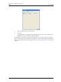
handle Device Management on another IMS2, see Figure 5.
Figure 5.
IMS2-A
Device
Manager
DECT
OAP
Server
DECT
OAP
External
Application
519
IMS2-B
Figure 5. Example of paging in a multiple IMS2 solution with OAP and DECT.
Configuration for the setup
The basic configuration for this setup is described below.
•
IMS2-A
- Disable Device Management
In Configuration > Other Settings > Advanced Configuration > Device Management:
Remove IP addresses.
Click "Activate".
10 January 2011 / Ver. E
14
Installation and Operation Manual
IMS2
•
TD 92586GB
IMS2-B
- Disable the DECT interface
In Configuration > Other Settings > Advanced Configuration > General Settings > View
advanced parameters:
Set "DECT Interface" to Disabled.
- Enable Device Management for the DECT system:
In Configuration > Other Settings > Advanced Configuration > Device Management:
Replace the address "127.0.0.1/DECT" with the IP address of IMS2-A plus
"/DECT", that is, if IMS2-A has the IP address 192.168.0.2, change to
"192.168.0.2/DECT".
Click "Activate".
See Figure 6.
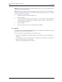
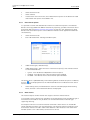
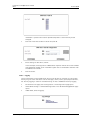
Figure 6.
Figure 6. Setting the IP address.
Example: Migration to a double IMS2 solution
This example assumes that the original system uses one IMS2. Basically, the system setup is
the same, but the original system with a single IMS2 has to be configured for a higher level
of messaging traffic.
Change the following settings in the original IMS2:
•
IMS2-A
- Disable Device Management:
In Configuration > Other Settings > Advanced Configuration > Device Management:
Remove the address "127.0.0.1/DECT".
Click "Activate".
- Export all device management data from IMS2-A:
In Device Manager > Numbers:
Select all Numbers.
In the menu, select Number > Export.
In Device Manager > Templates:
Select all templates.
In the menu, select Template > Export
10 January 2011 / Ver. E
15
Installation and Operation Manual
IMS2
TD 92586GB
Do the following settings in the added IMS2:
•
2.7.3
IMS2-B
- Disable the DECT interface
In Configuration > Other Settings > Advanced Configuration > General Settings > View
advanced parameters:
Set "DECT Interface" to Disabled.
- Enable Device Management for the DECT system:
In Configuration > Other Settings > Advanced Configuration > Device Management:
Replace the address "127.0.0.1/DECT" with the IP address of IMS2-A plus
"/DECT", that is, if IMS2-A has the IP address 192.168.0.2, change to "192.168.0.2/
DECT".
Click "Activate".
- Import all device management data to IMS2-B:
In Device Manager:
In the menu, select File > Import > Numbers...
In the menu, select File > Import > Templates...
High Messaging load in WiFi
This solution applies to:
•
•
•
systems with high messaging load
systems with high requirements on maximum message burst throughput
when requiring maximum shared phone performance in a system
When the messaging load is too high, a single IMS2 cannot handle both messaging and
device management effectively. Typically, this occurs when the messaging load is more than
4 000 messages per hour (or an equivalent amount of central phonebook enquires).
A solution to this situation can be achieved by running the messaging on one IMS2 and to
handle Device Management on another IMS2, see Figure 7.
Note: WLAN and OAP server must be run on an IMS2 (in this case IMS2-A), not an IMS/IP.
Figure 7.
IMS2-A
Device
Manager
WLAN
OAP
Server
WLAN
OAP
External
Application
554
IMS2-B
Figure 7. Example of paging in a multiple IMS2 solution with OAP and WLAN.
Configuration for the setup
The basic configuration for this setup is described below.
•
IMS2-A
- In Configuration > Other Settings > Advanced Configuration > Device Management:
Remove IP addresses.
Click "Activate".
10 January 2011 / Ver. E
16
Installation and Operation Manual
IMS2
•
TD 92586GB
IMS2-B
- Change IP address:
In Configuration > Other Settings > Advanced Configuration > Device Management:
Replace the address "127.0.0.1/WLAN" with the IP address of IMS2-A plus
"/WLAN", that is, if IMS2-A has the IP address 192.168.0.2, change to "192.168.0.2/
WLAN".
Click "Activate".
See Figure 8 below.
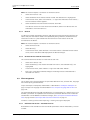
Figure 8.
Figure 8. Setting the IP address.
Example: Migration to a double IMS2 solution
This example assumes that the original system uses one IMS2. Basically, the system setup is
the same, but the original system with a single IMS2 has to be configured for a higher level
of messaging traffic.
Change the following settings in the original IMS2:
•
IMS2-A
- Change IP address:
In Configuration > Other Settings > Advanced Configuration > Device Management:
Remove the address "127.0.0.1/WLAN".
Click "Activate".
- Export all device management data from IMS2-A:
In Device Manager > Numbers:
Select all Numbers.
Number > Export.
In Device Manager > Templates:
Select all templates.
Template > Export
For settings in the added IMS2:
See Configuration for the setup on page 16.
•
IMS2-B
- Import all device management data to IMS2-B:
In Device Manager:
10 January 2011 / Ver. E
17
Installation and Operation Manual
IMS2
TD 92586GB
File > Import > Numbers...
File > Import > Templates...
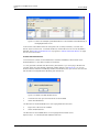
2.7.4
Multi-master IP-DECT systems and Multiple DECT systems
This solution applies to multi-master IP-DECT systems and multiple DECT systems, in
combination with a central number plan that is set up in an Ascom Enhanced System
Services (ESS) module.
Figure 9.
IMS2-A
IPBS-A
IMS2-B
IPBS-B
IMS2-C
IPBS-C
IMS2-D
IPBS-D
551
ESS
Figure 9. An example of a system configured with one ESS and several DECT or IPDECT systems, using one IMS2 per DECT or IP-DECT system.
Configuration for the setup
The basic configuration for this setup is described below.
10 January 2011 / Ver. E
18
Installation and Operation Manual
IMS2
•
TD 92586GB
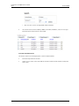
ESS setup:
See Installation and Operation Manual, Enhanced System Services (ESS), TD 92253GB for
details.
- For each DECT or IP-DECT system, configure a "category" for the DECT or IP-DECT
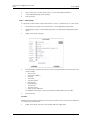
system, for example:
Category description
IP address
Service
IPDECT-A
172.20.10.11
DECT
IPDECT-B
172.20.10.12
DECT
IPDECT-C
172.20.10.13
DECT
IPDECT-D
172.20.10.14
DECT
- For each handset, set up a Call ID and add it to the number plan. It can be done for
individual handsets or for ranges, for example:
•
Call ID
Number/Address -> Category
1000
1000 -> IPDECT-A
1001
1001 -> IPDECT-A
2000
2000 -> IPDECT-B
2001
2001 -> IPDECT-B
3001
3001 -> IPDECT-C
4001
4001 -> IPDECT-D
Set all IMS2s to use the number plan in the ESS.
- In Configuration > Other Settings > Advanced Configuration > Other > UNS >
Operating mode:
"Operating Mode" shall be set to Forwarding.
"IP address of forward destination UNS" shall be set to the IP address of the ESS (here
192.168.0.20).
Click "Activate". The IMS2 now uses the ESS number plan.
Example: Migration to a multimaster IP-DECT solution
This example assumes that the original system is a single IP-DECT system with one IMS2 and
no ESS.
•
•
•
Configure the ESS. For the specific settings for multiple IMS2, see ESS setup in
Configuration for the setup on page 18. See Installation and Operation Manual, Enhanced
System Services (ESS), TD 92253GB for details.
Configure the existing IMS2 to use the number plan in the ESS, see Configuration for the
setup on page 18.
Set up the added IP-DECT system.
10 January 2011 / Ver. E
19
Installation and Operation Manual
IMS2
3
TD 92586GB
Data Backup
All settings in IMS2 are stored as database files. It is strongly recommended to backup these
files on a regular basis, see 13.5 Backup the Configuration on page 118.
10 January 2011 / Ver. E
20
Installation and Operation Manual
IMS2
4
TD 92586GB
IMS2 General
4.1
Authentication Levels and Default Passwords
IMS2 has five different authentication levels:
•
•
•
•
•
The Messaging function, that is, creating and sending messages, can by default be done
by any user in the system and requires no password. However, if password protection of
NetPage shall be included, see 18.3 Password Protected Access to NetPage on page 150.
User rights is required for the administration of the phonebook. Default user name and
password are “user” and “password”.
Administrator rights is required for the setup, the configuration and administration of
IMS2, simple troubleshooting and changing passwords (except for the sysadmin
password). Default user name and password are “admin” and “changeme”.
System Administrator rights is used for advanced troubleshooting. It gives access to all
administration pages and the permission to change all passwords. Default user name
and password are “sysadmin” and “setmeup”.
Auditor rights gives basically the same access as Administrator rights, but without
permission to alter values. There is no access to the setup wizard or the Device Manager.
Default user name and password is "auditor" and "readonly".
Different levels of password policy can be set in IMS2, see 4.4 Password policy on page 23.
For information about password protection of NetPage, see 18.3 Password Protected Access
to NetPage on page 150.
10 January 2011 / Ver. E
21
Installation and Operation Manual
IMS2
4.2
TD 92586GB
Functionality matrix
The following matrix shows which functionality that can be used by the different
authentication levels.
anonymous
user
admin
sysadmin
auditor
Messaging
Yes
Yes
Yes
Yes
Yes
Phonebook
administration
NetPage login
No
Yes
Yes
Yes
No
View configuration
settings
No
No
Yes
Yes
Yes
IMS2 configuration
Access to the setup
wizard
No
No
Yes
Yes
No
Access to the
Device Manager.
No
Yes
Yes
Yes
No
Change passwords
No
No
Yes1
Yes
No
1.Admin cannot change password for sysadmin.
4.3
Set passwords
It is possible to set passwords for the different users via the Advanced Configuration page.
1
Click “Configuration” on the start page. The Configuration page opens.
2
Select Other Settings > Advanced Configuration. The Advanced Configuration page
opens.
3
Under Security, click "Change Passwords".
4
Click the user to change password for.
5
Enter your user name and password. Enter the new password and confirm the
password.
6
Click "Ch. Passwd".
10 January 2011 / Ver. E
22
Installation and Operation Manual
IMS2
4.4
TD 92586GB
Password policy
The required password complexity can be set in IMS2, follow this instruction:
1
Click “Configuration” on the start page. The Configuration page opens.
2
Select Other Settings > Advanced Configuration. The Advanced Configuration page
opens.
3
Under Security, select "Password policy".
4
Set the password policy.
5
Click "Activate".
It is also possible to select previous or factory settings by clicking the corresponding button,
respectively.
4.5
Web access security settings
When secure mode is enabled, only secure access via HTTPS and FTPES is allowed. HTTP is
automatically redirected to HTTPS and FTP access is not allowed.
The web access security level can be set as follows:
1
Click “Configuration” on the start page. The Configuration page opens.
2
Select Other Settings > Advanced Configuration. The Advanced Configuration page
opens.
3
Under Security, select "Web access".
4
Select if Secure Mode shall be enabled or not.
5
Click "Activate"
It is also possible to select previous or factory settings by clicking the corresponding button,
respectively..
10 January 2011 / Ver. E
23
Installation and Operation Manual
IMS2
4.6
TD 92586GB
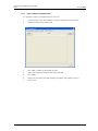
Configuration Page
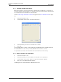
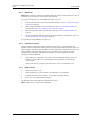
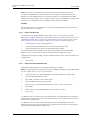
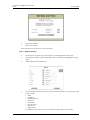
In order to reach the IMS2 Configuration page (see Figure 10), click
the IMS2 start page.
in
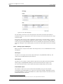
Figure 10.
Figure 10. The IMS2 Configuration page.
If you have system administrator or administrator rights, and clicking the Configuration
button or the Phonebook button on the start page, you will be able to access the complete
IMS2 configuration page
In the Configuration page, system information is shown, for example host name, IP address
and MAC Address.
10 January 2011 / Ver. E
24
Installation and Operation Manual
IMS2
4.7
TD 92586GB
Icons
On the IMS2 pages the following icons may be shown:
Click this icon to return to the IMS2 start page.
Click this icon to return to the IMS2 Configuration top page.
Click this icon to create a shortcut in the Internet browser.
10 January 2011 / Ver. E
25
Installation and Operation Manual
IMS2
4.8
TD 92586GB
Certificates
Certificates are used to increase security by encryption. A self-signed digital certificate is
created during the first start-up of IMS2. This certificate is issued to the MAC address of the
module. It is possible to import a certificate or to create one in the IMS2.
Note: It is also possible to use certificates to control if VoWiFi handsets are authorized to
access a WLAN, see 8.5.3 Manage Certificate for a VoWiFi Handset on page 49.
4.8.1
Import certificates
It is possible to import certificates to IMS2. These certificates may be created by a system
administrator with IT security responsibility. IMS2 uses PKCS#12 files, which include keys
and certificates.
For instructions on how to import a PKCS#12 file, follow this instruction:
1
On the IMS2 start page, select "Configuration". The IMS2 Configuration page opens.
2
Select Other settings > Advanced configuration. The IMS2 Advanced Configuration
page opens.
3
Under "Certificates", click "Import".
4
On the Certificates Import page, you can locate a certificate file. Enter file name and a
valid password. The certificate is tied to a specific password which should be
delivered with the file.
5
Click "Import file". The file is imported to IMS2.
6
Click "Close".
You may have to ask the network administrator for PKCS#12 files.
When starting, there may be a warning about the security certificate. This warning can be
ignored.
10 January 2011 / Ver. E
26
Installation and Operation Manual
IMS2
4.8.2
TD 92586GB
Create certificate
It is possible to create certificates in IMS2. For instructions on how to create a PKCS#12 file,
follow this instruction:
1
On the IMS2 start page, click "Configuration". The IMS2 Configuration page opens.
2
Select Other settings > Advanced configuration. The IMS2 Advanced Configuration
page opens.
3
Under Certificates, select "Create".
4
On the Create Self Signed Certificate page, enter valid parameters for your certificate
file. "Validity" and "Common name" are mandatory.
Due to security reasons, some characters in the ASCII-table are not allowed to use
in the fields Common Name, Organization Unit, Organization, Locality, State or
Province, and Country when creating a certificate.
Among these are:
5
[
]
(
)
{
}
$
&
\
|
"
`
'
?
~
>
<
^
\n \r
*
Click "Create Certificate". A certificate file is saved and the web server is restarted.
10 January 2011 / Ver. E
27
Installation and Operation Manual
IMS2
5
TD 92586GB
IMS2 Setup Wizard and Configuration
5.1
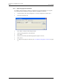
Basic Configuration Steps
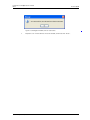
Figure 11.
Figure 11. The Setup Wizard in IMS2.
The first time and as long as the IMS2 is not configured, the setup wizard will start
automatically when logging on from a web browser. Requires “admin” or “sysadmin”
password, refer to 4.1 Authentication Levels and Default Passwords on page 21.
1
Log on to IMS2.
The setup wizard will open and help you with the basic configuration. The setup
wizard includes the following settings:
•
•
•
•
•
•
•
•
•
•
Network setup – can be set manually or via DHCP
License number – the type of license determines the functionality
Type of connected wireless phone system – the exchange used by the handsets in
the system
DECT IP address – IP address to the DECT exchange (if connected via IP)
Serial Interface – Select which serial interface to use (using ESPA, Ascom Line
protocol or TAP)
Default messaging destination
Date and time properties/settings – for time stamps on activities
Central Phonebook properties – database to use when searching (local
phonebook on IMS2, or LDAP server).
LDAP properties – (only visible if LDAP is selected in the Central Phonebook
Properties)
Passwords – change from default to site specific passwords
2
Configure the Central phonebook (but only if an LDAP server is not used), see 7
Central Phonebook Administration on page 32.
3
Create a security backup.
It is recommended to create a security backup of all settings (to facilitate the
configuration in case of a software upgrade). See 13.5 Backup the Configuration on
page 118.
10 January 2011 / Ver. E
28
Installation and Operation Manual
IMS2
5.2
TD 92586GB
Optional Settings
Some of the optional settings in IMS2 are included in the basic license, other requires an
additional license. See 1.4 How to Use this Document on page 6.
•
•
•
•
•
•
•
•
Alarm Handling – alarm actions can be set (type of trigger and what action to take).
Refer to chapter 13.2 Alarm Handling on page 106.
Status – information about the site and information about supervised modules and
equipment can be exported for troubleshooting purposes. Refer to chapter 13.3 Status
on page 112.
Change Language – it is possible to change user interface language, refer to chapter
18.1 Customize the Language for IMS2 Menus on page 138.
Input/Output setup – makes it possible to define inputs (for example a switch or button)
and outputs (for example to turn on a siren or to close a door). Inputs can be used as
trigger conditions and outputs can be used as actions. Refer to chapter 13.4 Input/
Output Setup on page 115.
Customize the Start page and NetPage GUI – the Start page and the NetPage user
interface can be customized to suit the individual customer requirements concerning
functionality. Refer to chapter 18.2 Customize the User Interface (GUI) on page 142.
Remote Connection – makes it possible to establish a remote connection to a customer
site. This makes it possible to configure and maintain sites, independent of distance.
Refer to chapter 14 Remote Management on page 128.
Open Access Protocol (OAP) – makes it possible to communicate with other systems that
are connected to the IMS2. Refer to chapter 20 Open Access Protocol (OAP) on page 159.
Digit Manipulation – makes it possible to set the way telephone numbers are converted
in telephone number lists. See 13.1.7 Digit Manipulation in Central Phonebook on page
101.
10 January 2011 / Ver. E
29
Installation and Operation Manual
IMS2
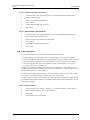
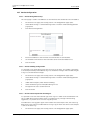
6
TD 92586GB
Operation - Messaging
Creating and sending messages requires no password and can be done by any user in the
system. Depending on license, different GUIs are displayed.
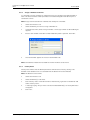
Figure 12.
Figure 12. Messaging in IMS2.
For configuration of messaging, see 17 Messaging on page 133.
6.1
Messaging Tool
The Messaging Tool GUI is displayed on IMS2s without additional license.
In order to send a message, do as follows:
6.2
1
On the IMS2 start page, click "Messaging". The Messaging Tool page opens.
2
Enter telephone number in the top text field.
3
Enter message in the bottom text field.
4
Click
. The message is sent to the receiver.
NetPage
The NetPage messaging tool is shown for IMS2s with a license that includes NetPage.
To create and send messages:
1
On the IMS start page, click "Messaging".The Netpage window opens.
10 January 2011 / Ver. E
30
Installation and Operation Manual
IMS2
TD 92586GB
2
Click either the “Search” button to search a number from the number list, or enter a
number in the Call ID field. It is possible to write several Call IDs separated by a
semicolon.
3
Enter message text in the Message text field.
4
Select Beep Code and Priority.
5
Click “Send”.
10 January 2011 / Ver. E
31
Installation and Operation Manual
IMS2
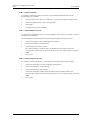
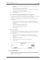
7
TD 92586GB
Central Phonebook Administration
The phonebook administration in this chapter requires authentication on user level. For
further configuration, see 7 Central Phonebook Administration on page 32
Figure 13.
Figure 13. Phonebook in IMS2.
The phonebook makes it possible for users to search and find phonebook entries from a
handset in the system.
If a local phonebook is used the entries must be added, either by creating them manually,
refer to 7.1.1 Add Entries to the Central Phonebook on page 32, or importing them from a
CSV file, see 7.2.1 Import Entries to the Central Phonebook from a CSV File on page 34.
7.1
Edit the Central Phonebook
7.1.1
Add Entries to the Central Phonebook
The entries in the phonebook can be filled in manually.
1
On the start page, click “Phonebook”.
2
Enter User name and Password. Click “OK”.
3
Select Phonebook > Edit.
4
Click “Add” button and enter the information needed in the text fields as described in
Add Entry Manually below.
Add Entry Manually
1
2
Enter the following settings in the text fields:
Setting
Description
Last Name:
The family name
First Name:
The first (given) name
Number:
The telephone number
To add several rows click “Add” again.
10 January 2011 / Ver. E
32
Installation and Operation Manual
IMS2
3
7.1.2
TD 92586GB
Click “Save”.
Sorting of Central Phonebook
The entries in the Central phonebook can be sorted on Last Name, First Name or Number.
1
On the start page, click “Phonebook”.
2
Enter User name and Password and click “OK”. The Edit Central Phonebook page
opens.
3
To sort the entries, click the arrows in the list’s title bar.
The Edit Central Phonebook page can also be reached from the IMS2 Configuration page, via
"Other settings" > "Advanced Configuration".
7.1.3
Delete a single entry
Entries in the Central phonebook can be deleted in the following way:
1
On the start page, click “Phonebook”.
2
Enter User name and Password. Click “OK”.
3
Select Phonebook > Edit. The Edit Central Phonebook page opens.
4
Locate the entry to be deleted. Click the
5
Click "Save". The entry is deleted.
10 January 2011 / Ver. E
button in the same row.
33
Installation and Operation Manual
IMS2
7.1.4
TD 92586GB
Delete All
All entries in the phonebook can be deleted by clicking the "Delete All" button.
7.2
1
On the start page, click “Phonebook”.
2
Enter User name and Password. Click “OK”
3
Select Phonebook > Edit. The Edit Central Phonebook page opens.
4
Click "Delete All". It is now possible to mark entries not to be deleted by clicking the
icon
. If this icon is clicked, it disappears and the icon
is displayed.
5
Click "Save". All entries marked with a blue arrow are deleted. The entries that are
marked
are kept.
Import and Export a Central Phonebook
7.2.1
Import Entries to the Central Phonebook from a CSV File
The CSV file to be imported to the Central phonebook shall have the following format:
First name;Last name;Telephone number
Different separators may be used, see below:
Warning: When importing a Central phonebook file in CSV format, existing entries are
deleted.
1
Click “Phonebook” on the start page.
2
Enter User name and Password and click “OK”.
3
Select Phonebook > Import/Export.
4
Select separator for the CSV file.
Different separators may be used in a delimiter-separated file. Currently, the IMS2
supports import of files with the separators semicolon, comma or TAB.
5
Click “Browse” to locate the CSV file in the system.
6
Click “Import”.
10 January 2011 / Ver. E
34
Installation and Operation Manual
IMS2
7.2.2
TD 92586GB
Export the Central Phonebook to a CSV File
The complete Central phonebook can be exported to a CSV file for example for editing or
backup reasons.
1
Click “Phonebook” on the start page.
2
Enter User name and Password. Click “OK”.
3
Select Phonebook > Import/Export. Click “Export”.
4
Click “Save” in the window that appears.
5
Enter a name of the file and select in which folder the file shall be saved.
6
Click “Save”.
10 January 2011 / Ver. E
35
Installation and Operation Manual
IMS2
8
TD 92586GB
Device Manager
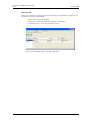
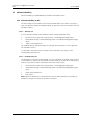
Figure 14.
Figure 14. Device Manager in IMS2.
8.1
Description
This section gives a description of the Device Manager in IMS2 and how it is intended to be
used.
The Device Manager can manage large sets of devices and contains a solution for:
• Centralized software upgrade on a set of devices and configuration of devices
• Central database storage for all device settings
• Upgrade of license for handset
In the Device Manager, much of the work is done with Devices, Numbers and Templates.
IMPORTANT: The IMS2 server must always be switched on.
10 January 2011 / Ver. E
36
Installation and Operation Manual
IMS2
8.1.1
TD 92586GB
Device Manager terminology
This section gives a brief description of the basic terminology in the Device Manager.
Device
Can be a charger or a handset that can be connected to
IMS2.
Number
The complete settings for a single device. Also chargers
have a Number.
Template
General settings for a specific device type. A template
can be applied to several Numbers of the same device
type.
License
Licensed functionality for a device.
Tabs
In the Device Manager there are different views, or tabs.
In these tabs, the information for devices, Numbers,
templates and licenses are shown.
Parameter definition file
a file including all possible settings for a certain device
type. Templates are created from parameter definition
files.
Software
The software used in devices. The device software can
be updated via IMS2.
Version
Parameter definition files and device software are
indicated by versions.
Package file
A file that can contain other files, such as parameter
definition files, software files and template files.
Importing
Different types of files can be imported. Note that if a
software file should be imported, it may have been
delivered in a package file.
Associate
Before being able to synchronize parameters between
IMS2 and devices, it is necessary to associate a Number
with the device. Association includes all parameters. If it
exists on that device type, it also includes Contacts.
Assign
It is possible to assign a Number to a device that has not
yet been assigned a Number in the Device Manager.
Assign includes only the parameters defining the
Number.
8.1.2
Device Manager Usage
The following list is a short description to give a basic understanding on how to use the
Device Manager with devices. It is not intended to be used as a work flow description.
•
•
•
•
•
Import a parameter definition file of the corresponding device type to IMS2.
Create a template from the parameter definition file.
Add a device to IMS2.
Create a new Number for the corresponding device type.
Associate the Number with the device.
Refer to applicable handset configuration manual for a description of the work flow.
10 January 2011 / Ver. E
37
Installation and Operation Manual
IMS2
8.1.3
TD 92586GB
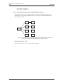
The Device Manager GUI
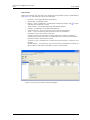
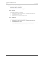
The Device Manager window consists of three areas: Menu, Toolbar and Work Area.
The Toolbar has four tabs: Devices, Numbers, Templates and Licenses (Figure 15). When one
of these tabs is selected the available device types will be shown in the left hand pane of the
work area. The right pane shows the devices, numbers or templates which have already
been configured.
Figure 15.
Figure 15. Device Manager Window Area.
In the upper part of the Work area, there are search fields where different search criteria can
be selected depending on which tab that is displayed.
Sort and Filter the List
By default, the lists are sorted as follows:
Devices tab - sorted by Device ID
Numbers tab - sorted by Number
Templates tab - sorted by Name
Licenses tab - sorted by Device ID
To sort the list by any other column, click the appropriate column heading. To reverse the
sort order, click the column heading again. The sorting order is indicated by an up or down
arrow in the column heading.
Filter the List
By default, the list in each tab shows all available Devices, Numbers or Templates. It is
possible to filter the list by selecting the desired device type in the Device types: column in
the left pane.
10 January 2011 / Ver. E
38
Installation and Operation Manual
IMS2
8.1.4
TD 92586GB
General Colour Coding
This colour coding is valid for the lists under the tabs:
•
•
If the version number is shown in red, the Device Manager has found no parameter
definition files supporting that device type.
If the version number is shown in dark red, the parameter definition file is compatible,
but does not have exactly the same version as the device.
Colour coding for parameter and template editing
In the parameter and template editing windows, the following colour coding is used:
Colour
Context
Description
Black
General
Normal
Dark blue
For templates and parameter editing Parameter has been edited during the
current session
Purple
For templates
Red
For templates and parameter editing Value not valid
Turqoise
For templates and parameter editing The value differs from the default value
8.1.5
The parameter is included in the
template (checked)
Navigation
For keyboard shortcuts, see Appendix E: Device Manager Keyboard Shortcuts on page 187.
10 January 2011 / Ver. E
39
Installation and Operation Manual
IMS2
8.1.6
TD 92586GB
Tabs
The information in IMS2 is shown in different tabs:
•
•
•
•
Devices tab
Numbers tab
Templates tab
Licenses tab
In each of these tabs, specific information is shown in lists about devices, Numbers,
templates or licenses. Some of the information overlaps, for example Device ID, which is tied
to both a specific device and to a specific Number.
The operations that can be done in the Device Manager are done from these tabs and from
the menu. Different menues are accessible in the different tabs.
Devices Tab
Select the “Devices” tab. The view shows all devices configured at the site in a detailed list
(see figure 16 on page 41). The following columns are displayed:
•
•
•
•
•
Device ID – the unique identifier of the device.
Device type – the device model.
Software version – shows the version of the software in the device.
Parameter version – shows the version of the parameters in the Number.
Upgrade status – might show one of the following symbols:
– software upgrade in progress.
It is also possible to see a progress bar when the device is being upgraded.
– software upgrade Pending, Request sent, or Accepted (a green arrow).
– software upgrade Scheduled or Retrying.
– the last upgrade Failed or Aborted (a red broken arrow).
– “Completed”, no symbol is shown
Note: A software upgrade from IMS2 should be done on one device to start with. If
successful, the remaining devices can be updated in one operation.
•
•
Online – shows if the device is connected to the Device Manager. The symbol
indicates a connected device.
Latest Number - shows the latest known Number for a device.
10 January 2011 / Ver. E
40
Installation and Operation Manual
IMS2
TD 92586GB
Figure 16.
Figure 16. The Devices tab showing a list of devices in a system.
10 January 2011 / Ver. E
41
Installation and Operation Manual
IMS2
TD 92586GB
Numbers Tab
Select the “Numbers” tab. The view shows all Numbers configured at the site in a detailed
list (see Figure 17). The following columns are displayed:
•
•
•
•
•
•
•
•
Number – the unique identifier of the Number. The identifier is unique for that
device type.
Device type – the device model the Number is intended for
Parameter version – shows the version of the parameters in the Number
Device ID – the unique identifier of the device that the Number is associated to
Online – shows if the device the Number is associated to is online. The
symbol
indicates an online device
Status – shows the parameter synchronization status. A Number can also be
queued for synchronization. Several different indications are used, for example
Synchronizing, Sync queued, Save queued, Synchronized, etc.
When the Number is offline, the database status is shown; Synchronized or Not
synched.
Saved – shows if the Number’s parameters have been stored in the database. The
symbol indicates that the parameters have been stored
Last run template - indicates which template that was last run for that Number
Figure 17.
Figure 17. The Numbers tab showing a list of Numbers in a system.
10 January 2011 / Ver. E
42
Installation and Operation Manual
IMS2
TD 92586GB
Templates Tab
Select the “Templates” tab. The view shows all templates in a detailed list (see Figure 18).
The following columns are displayed:
•
•
•
Name – the name of the template
Device type – the device model the template is intended for
Parameter Version – shows the parameter version
Figure 18.
Figure 18. The Templates tab in the Device Manager.
10 January 2011 / Ver. E
43
Installation and Operation Manual
IMS2
TD 92586GB
Licenses Tab
Select the “Licenses” tab. The view shows all devices configured at the site in a detailed list
(see Figure 19). The following columns are displayed:
•
•
•
•
•
•
•
Device ID – the unique identifier of the device.
Device type – the device model.
Online – shows if the device is connected to the Device Manager. The
symbol
indicates that the device is online
Serial number – the number identifying the device hardware
Number – The Number associated with the device.
Software version – shows the version of the software in the device
Status – shows the license synchronization status for the devices.
Examples of status that can be shown are:
"Sending" means that the IMS2 is sending license information to the device.
"Server failure" means that there is some kind of error with the communication
between the IMS2 and the license server.
"License too old" - The device has a newer license than the IMS2. A refresh has to
be done.
"Needs update" - An attempt to move a license from one handset to another has
been made, but the latest license does not exist in the handset.
Figure 19.
Figure 19. The Licenses tab in the Device Manager.
10 January 2011 / Ver. E
44
Installation and Operation Manual
IMS2
8.2
TD 92586GB
Log In
Note: When an attempt is made to start IMS2 Device Manager, a dialogue window might be
displayed with a warning that the program’s digital signature cannot be verified. The text is
displayed in the language used in the computer’s operating system. Click "Run" (or the
equivalent term in the operating system language).
Note: Three clients can be logged in at the same time, but to avoid conflicts make sure that
only one at a time is updating Numbers.
8.3
1
Open the IMS2 by entering its IP address in a web browser.
2
Click the "Device Manager" button.
3
Select User ID and enter password, see 4.1 Authentication Levels and Default
Passwords on page 21.
4
Click “OK”. The Device Manager starts.
Close the Device Manager
In the File menu, click “Exit”. The Device Manager shuts down.
8.4
Templates in Device Manager
8.4.1
Create a Parameter Template
It is usually desirable to create a customized parameter template that can be applied to all
devices of a certain device type.
1
Select the “Templates” tab.
2
In the Template menu, click “New”. The New template dialogue opens.
3
Select device type and parameter version, type in a name for the template, and click
“OK”. The view switches to the Edit Template parameter view.
Note: If you cannot find your device type and/or parameter version in the list, the Device
Manager needs to be updated with new parameter definition files, see 8.9.3 Import
Parameter Definition Files on page 70.
10 January 2011 / Ver. E
45
Installation and Operation Manual
IMS2
TD 92586GB
4
Select the parameters you want to be saved in the template by selecting the
checkbox to the left of each parameter.
5
Change the parameters to the desired values.
6
Click “OK”.
8.4.2
Create a Parameter Template from a Number
It is also possible to create a template from a Number in the Device Manager.
1
Select the “Numbers” tab.
2
Mark the Number you want to use.
3
Right-click on the Number and select “Use as template...”
The Enter template name dialogue opens.
4
Enter a name for the template.
5
Click “OK”.
6
The Edit template window opens. Continue with 4 to 6 in 8.4.1 Create a Parameter
Template on page 45.
Note: When the Edit template window is opened from the "Use as template" command, an
extra drop-down list is shown in the bottom left corner. This setting decides which
parameters that shall be copied from the Number. If "All parameters" is selected, the
synchronization time will be longer.
It is also possible to create a template from a portable that is online but not stored in the
database. The template will contain all parameters for the device except for those that are
Number specific.
8.4.3
1
Rename a template
Select the "Templates" tab.
10 January 2011 / Ver. E
46
Installation and Operation Manual
IMS2
TD 92586GB
2
Select the template you want to rename. The selected row is highlighted.
3
In the Template menu, select "Rename..." or right-click and select "Rename...". The
Rename template dialogue opens.
4
Enter a new name in the "New name" text field.
5
Click "OK". The Rename template dialogue closes and the new name appears in the
list in the Templates tab.
8.4.4
Copy a template
1
Select the "Templates" tab.
2
Select the template you want to copy. The selected row is highlighted.
3
In the Template menu, select "Copy...", or right-click and select "Copy...". The Copy
template dialogue opens.
4
Enter a new name in the "New name" text field.
5
Click "OK". The Copy template dialogue closes and the new template appears in the
list in the Templates tab.
8.4.5
Edit a template
1
Select the "Templates" tab.
2
Select the template you want to edit. The selected row is highlighted.
3
In the Template menu, select "Edit..." or right-click and select "Edit...". The Edit
template window opens.
4
In the Edit template window, edit the parameters that shall be edited.
5
Click "OK". The Edit template window closes.
8.4.6
Delete a template
1
Select the "Templates" tab.
2
Select the template you want to delete. The selected row is highlighted.
3
In the Template menu, select "Delete", or right-click and select "Delete", or press the
Delete button. The Delete template dialogue opens.
4
Click "Yes". The Delete template dialogue closes and the template is deleted.
10 January 2011 / Ver. E
47
Installation and Operation Manual
IMS2
8.4.7
TD 92586GB
Upgrade a template
1
Select the "Templates" tab.
2
Select the template you want to upgrade. The selected row is highlighted.
3
In the Template menu, select "Upgrade..." or right-click and select "Upgrade...". The
Upgrade template dialogue opens.
4
Select the parameter version to upgrade to.
5
Click "OK". The template is upgraded and the dialogue closes.
8.4.8
Apply a template
1
Select the "Templates" tab.
2
Select the template you want to use. The selected row is highlighted.
3
In the Template menu, select "Apply to...", or right-click and select "Apply to...". The
Apply template window appears.
4
If needed, select search parameters or click "Show all".
5
Select Number(s) to apply the template on.
6
Click "OK". The template is applied and the window closes.
10 January 2011 / Ver. E
48
Installation and Operation Manual
IMS2
8.5
TD 92586GB
Numbers
8.5.1
Create New Numbers
1
Select the “Numbers” tab.
2
In the Number menu, select “New...”. Alternatively, right-click in the Numbers list and
select “New...”.
3
In the Device type drop-down list, select device type.
4
In the Parameter version drop-down list, select the parameter version.
5
In the Template drop-down list, select which template to run on the Number. This is
optional and therefore “None” can be selected.
6
In the Prefix field, enter the Number’s prefix (if needed).
7
Select one of the following options:
•
To create a single Number, select the Single option and enter the call number. Click
“OK”.
• To create a range of Numbers, select the Range option. Enter the start call
number, end call number, and click “OK”.
Note: The maximum range that can be added at a time is 100 Numbers.
Note: If a dialogue window "A maximum of...numbers can exist in the system" appears (see
Figure 20), see 8.7 License Restrictions for Device Handling on page 62 for more
information.
Figure 20.
Figure 20. Dialogue window, Maximum numbers allowed (example)
8.5.2
Save a Number to Database
An online device can be saved to the database.
1
Select the Numbers tab.
2
Select the Number.
3
In the Number menu, select "Save". Alternatively, right-click the Number and select
“Save”
Tip: An online device can automatically be enabled and saved (default), see 8.11.1
Automatically enable new devices settings on page 80 for more information.
8.5.3
Manage Certificate for a VoWiFi Handset
Note: This function is applicable for VoWiFi handsets only. In addition, the handset must be
online in the Device Manager.
Certificate(s) is used for authorizing a VoWiFi handset to access a WLAN system using
Extensible Authentication Protocol (EAP) .
10 January 2011 / Ver. E
49
Installation and Operation Manual
IMS2
TD 92586GB
There are two types of certificates: Root certificate and client certificate.
The VoWiFi handset using the root certificate to control if the WLAN system is trusted. If the
system is trusted, the handset send its client certificate to show that it is authorized to
access and log on the system.
The root certificate contains a public key and can be downloaded to the handset via Device
Manager or via WinPDM. The client certificate contains both a public key and a private key
and can only be downloaded to the handset via the WinPDM.
The following must be done to be able to use certificates:
•
•
Import certificates to handset, see Edit Certificate.
Select which client certificate to use by setting a EAP client certificate parameter, see the
Configuration Manual for the VoWiFi handset.
Edit Certificate
1
Select the “Numbers” tab.
2
In the Number menu, select “Edit certificates”. Alternatively, right-click in the
Numbers list and select “Edit certificates”.
The following information is displayed:
•
•
•
•
•
The number of the device
The device type
The parameter version
The online status of the device
Imported certificates (if any)
3
Click the corresponding “Edit“ button to edit the certificate.
4
Locate the certificate file and click “Open“.
5
If the certificate is passport protected, an Enter Password dialogue appears. Enter the
password and then click “OK”.
A Confirm Certificate windows appears, see Figure 21. The following information is
displayed:
•
•
•
•
The algorithm of the certificate
The validity status of the certificate
The validity period of the certificate
The issuer of the certificate
10 January 2011 / Ver. E
50
Installation and Operation Manual
IMS2
•
TD 92586GB
The authorized users of certificate (issued to).
Figure 21.
Figure 21. Confirm Certificate Window
6
Import the certificate to the device by clicking “Yes“.
If needed, repeat step 3 - 5 for editing additional Root-certificates.
View Certificate Details
1
Select the “Numbers” tab.
2
In the Number menu, select “Edit certificates”. Alternatively, right-click in the
Numbers list and select “Edit certificates”.
3
Select the certificate to view by clicking the corresponding “Details“ button.
A Certificate details window appears, see Figure 22. The following information is displayed:
•
•
•
•
•
The algorithm of the certificate
The validity status of the certificate
The validity period of the certificate
The issuer of the certificate
The authorized users of certificate (issued to)
Figure 22.
Figure 22. Certificate Details Window
Remove Certificate
1
Select the “Numbers” tab.
2
In the Number menu, select “Edit certificates”. Alternatively, right-click in the
Numbers list and select “Edit certificates”.
3
Select the certificate to remove by clicking the corresponding “Remove“ button.
10 January 2011 / Ver. E
51
Installation and Operation Manual
IMS2
4
TD 92586GB
A Remove certificate window opens. Click “Yes“ to remove the selected certificate.
The certficate is now removed from the handset.
8.5.4
Parameter Transfer between a Device and the Device Manager
When a device is connected, it is synchronized with the associated Number in the Device
Manager, see 8.6.2 Synchronize a Device on page 58.
Note: When parameters have been edited and the device is synchronized, only the edited
parameters will be sent to the device.
10 January 2011 / Ver. E
52
Installation and Operation Manual
IMS2
8.5.5
TD 92586GB
Edit Parameters
The Edit parameters window shows the set of parameters relevant to the Number that is
being edited. The parameter groups are organized in a tree structure in the left pane, with
the parameters in the current node in the right pane. The parameter list has one column
with the parameter name, and another column shows the parameter value. This can be for
example a numerical value, a boolean value, or text. Clicking the icon
will give a short
description of the selected parameter.
1
Select the “Numbers” tab.
2
Select the Number. The selected row is highlighted.
3
Click “Edit” in the Number menu. Alternatively, right-click and choose “Edit”, or
double-click the Number.
4
In the left pane, select parameter.
5
In the Value column, make the changes.
When a parameter has been edited, the name of the node to which the parameter
belongs changes to a blue colour.
(Click “Cancel” if you want to undo all parameters edited since your last save and
return to the main window.)
6
Click “OK” to save the changes.
Note: When you save the parameters, they are automatically sent to the device if it is
online.
8.5.6
Run a Template to set Parameter Values
If a template has been created for a device type, it can be used to set the parameter values
for a range of devices, or a single device. The command to use is Run template.
1
Select the “Numbers” tab.
2
Select the Number(s) you want to run the template on.
3
In the Number menu, click “Run template...”. Alternatively, right-click the Number in
the Number list and select “Run template...” from the menu that appears.
10 January 2011 / Ver. E
53
Installation and Operation Manual
IMS2
4
Select a template from the Template list.
5
Click “OK”.
TD 92586GB
If the parameters in the database have been edited but not yet sent to the device it is
indicated with “Not synched” or "Update queued".
If the Number has not been associated with a device, it is now possible to do so. Connect a
device and associate it with a Number in the database. The parameters will automatically be
sent from the Device Manager to the device. See 8.5.7 Associate a Number with a Device on
page 55.
10 January 2011 / Ver. E
54
Installation and Operation Manual
IMS2
8.5.7
TD 92586GB
Associate a Number with a Device
Before being able to synchronize parameters between IMS2 and devices, it is necessary to
associate a Number with the device. It is possible to enter several Device IDs in advance and
to associate them with a Number at a later moment.
See also 8.6.6 Assign a Number to a device on page 61 and 8.6.5 Add new Device on page
59.
1
Select the “Numbers” tab.
2
In the Number menu, select “Associate with device...”.
3
Select the device you want to associate with in the list.
4
Click “OK”.
If the selected device is online, it will immediately be updated with the selected Number. If
the selected device is not online, it will be updated the next time it is online.
It is possible to associate several Numbers with several devices simultaneously.
8.5.8
Delete a Number in the Site Database
1
Select the “Numbers” tab.
2
Select the Number you want to delete. The selected row is highlighted.
3
In the Number menu, select “Delete”, or right-click and select “Delete”.
4
Click “Yes” in the Delete Number dialogue.
The dialogue closes and the Number is deleted from the list.
10 January 2011 / Ver. E
55
Installation and Operation Manual
IMS2
8.5.9
TD 92586GB
Rename a Number
1
Select the "Numbers" tab.
2
Select the Number you want to rename. The selected row is highlighted.
3
In the Number menu, select "Rename..." or right-click and select "Rename...". The
Rename number dialogue opens.
4
In the "New prefix" field, enter a new prefix (if needed)
5
In the "New number" field, enter a new Number.
6
Click "OK". The Rename number dialogue closes and the new Number appears in the
list in the Numbers tab.
8.5.10 Copy a Number
When a Number is copied, the parameter settings and device type for that Number will be
copied to a new specified Number.
1
Select the "Numbers" tab.
2
Select the Number you want to copy. The selected row is highlighted.
3
In the Number menu, select "Copy...", or right-click and select "Copy...". The Copy
Number dialogue opens.
4
In the "New prefix" field, enter a new prefix (if needed).
5
In the "New number" field, enter a new Number.
6
Click "OK". The Copy number dialogue closes and the new Number appears in the list
in the Numbers tab.
8.5.11 Import Contacts
Note: The number for the handset must be saved, see 8.5.2 Save a Number to Database on
page 49.
Import Contacts From File
A file containing contacts can be imported to IMS2 and synchronized with handsets.
Contacts from 9d23/9d24 handsetscordless telephones must first be transferred to the file
using a SIM card programmer.
Note: When importing a local phonebook file, the local phonebook entries (if any) in the
handset will be replaced by the entries in the file.
1
In the Device Manager, select the Numbers tab.
2
Select a number.
3
In the Number menu, select “Import contacts” > “From file”. Alternatively, right-click
the Number in the Number list and select “Import contacts”> “From file” from the
menu that appears.
4
Find and select a file containing contacts. Click “Open”.
The contacts in the imported file are synchronized with the handset.
Import Contacts From Number
This feature enables transfer of contacts from one handset to another handset that has
been saved in the Device Manager.
10 January 2011 / Ver. E
56
Installation and Operation Manual
IMS2
TD 92586GB
Note: When importing number, the local phonebook entries (if any) in the handset will be
replaced by the imported numbers.
Note: Company phonebook contacts included in the Call contact list are not transferred to
the other handset using this feature. To upload the Company phonebook, see 8.9.8 Upload
Company Phonebook on page 75.
8.6
1
In Device Manager, select the Numbers tab.
2
Select a number.
3
In the Number menu, select “Import contacts” > “From number”. Alternatively, rightclick the Number in the Number list and select “Import contacts”> “From number”
from the menu that appears.
4
Select a number.
5
Click “OK”. The contacts are now imported to the handset.
Devices
A device can be a handsetor charger developed to work together with the Device Manager.
See the user manual for respective device.
All work with devices is performed from the “Devices” view.
•
•
•
•
Devices can be added by connecting the device to the system, or use the "Add device"
function.
It is possible to transfer the information for a Number from one device to a new device.
Devices can be reset to factory settings.
Devices can be updated with new software.
10 January 2011 / Ver. E
57
Installation and Operation Manual
IMS2
8.6.1
TD 92586GB
Add Devices
Note: Before connecting a device to the Device Manager, make sure the connection is set up
according to the instructions in the device´s User Manual.
If a range of new devices are to be added, the easiest way is to:
1
Create a template with all common parameter settings. See 8.4.1 Create a Parameter
Template on page 45.
2
Add a range of Numbers and run the template. See 8.5.1 Create New Numbers on
page 49 and 8.5.6 Run a Template to set Parameter Values.
3
Edit the parameters and change individual settings. See 8.5.5 Edit Parameters on
page 53.
4
Connect the devices and associate them with the Numbers in the database. See 8.5.7
Associate a Number with a Device on page 55.
A single device can be added in the same way.
8.6.2
Synchronize a Device
When parameters have been changed in a device, the device is synchronized with the
Number saved in the database. When a device is being synchronized, parameters that have
been changed in the device are uploaded to the Device Manager, and parameters that have
been changed in the Device Manager are sent to the device. If a parameter has been
changed in both the device and the Device Manager, the setting made in the Device
Manager will take precedence.
1
When a device is connected to the system running the Device Manager, and if the
Number is saved, and it has a parameter definition, the device is automatically
synchronized.
While synchronizing, a progress bar and a text is shown in the Numbers view.
8.6.3
Delete a Device
1
Select the “Devices” tab.
2
Select the device you want to delete. The selected row is highlighted.
3
In the Devices menu, select “Delete” or right-click and select “Delete”.
4
Click “Yes” in the Delete Device dialogue.
The dialogue closes and the device is deleted from the list.
Note: A device that is online cannot be deleted.
10 January 2011 / Ver. E
58
Installation and Operation Manual
IMS2
8.6.4
TD 92586GB
Replace a Device
If a device shall be replaced with a new device, it is possible to transfer its associated
Number including settings to a new device. The new device must be of the same device type
as the old one.
1
If the device to be replaced is still working, make sure that it is synchronized.
2
Shut off the old device or make a factory reset.
3
Connect the new device to the Device Manager.
4
Associate the new device to the Number associated to the old device according to the
instructions in 8.5.7 Associate a Number with a Device on page 55. The Number will
no longer be associated with the old device.
8.6.5
Add new Device
It is possible to enter several new Device IDs in advance into the Device Manager for later
association.
In order to simplify input when handling many devices, it is possible to use a bar code
reader. The bar code reader should send a carriage return after each item, but it is not
necessary. If carriage return is not sent, it is necessary to click “Create” after each read item.
1
Select the “Devices” tab.
2
In the Device menu, select “Add device”.
3
Select Device type and Parameter Version.
4
Enter a Device ID for the device, manually or by using a bar code reader.
5
The “Continuous registration” box can be used to select whether the “Create devices”
dialogue shall close after clicking “Create” or if it shall still be open.
6
If the bar code reader does not send carriage return, click “Create”.
Note: If a dialogue window "You cannot add any more devices due to license restrictions"
appears (see Figure 23), see 8.7 License Restrictions for Device Handling on page 62 for
information.
10 January 2011 / Ver. E
59
Installation and Operation Manual
IMS2
TD 92586GB
Figure 23.
Figure 23. Dialogue window, license restrictions
7
Repeat 4 to 6 if more devices are to be created, otherwise click “Close”.
10 January 2011 / Ver. E
60
Installation and Operation Manual
IMS2
8.6.6
TD 92586GB
Assign a Number to a device
It is possible to assign a Number to a device that has not yet been assigned a Number in
IMS2. This feature can be used if parameters have been changed on the device prior to
connection to IMS2.
Note: Assign shall not be done on a device that already has a Number.
1
Select the “Devices” tab.
2
Select the device you want to assign a Number for.
3
In the Devices menu, select “Assign number”. The Assign number to device dialogue
appears.
4
Enter a new number in the New number field. New prefix is optional. Click “OK”.
5
The new Number appears in the list in the Numbers tab.
Note: Some devices need to be restarted for the new numbers to be shown.
8.6.7
Factory Reset
Factory reset means that the device parameters will be reset to factory settings. The
Number in the database that is associated with the device will not be affected.
Note: The device must be online.
1
Select the “Devices” tab.
2
Select the device(s) to be reset.
3
Click “Factory reset” in the Device menu. Alternatively, right-click on the device and
select “Factory reset”.
4
A message saying “Do you want to reset the selected device(s) to factory defaults?”
will appear.
5
Click “Yes”.
10 January 2011 / Ver. E
61
Installation and Operation Manual
IMS2
8.7
TD 92586GB
License Restrictions for Device Handling
The license for IMS2 determines how many devices and numbers that can be added to the
Device Manager. See the following scenarios for more information.
Scenario 1
The IMS2 has the license WSM-LAM1 that allows to add 100 devices and 250 numbers.
Allowed Devices and Numbers Added Devices and
Numbers
Remaining Devices and
Numbers
100 Devices
90 Devices
10 Devices
250 Numbers
200 Numbers
50 Numbers
The administrator wants to add 20 devices according to 8.6.5 Add new Device on page 59.
When trying to add more devices than allowed, the following dialogue window (see Figure
24) appears:
Figure 24.
Figure 24. Additional devices cannot be added.
The administrator wants to add 60 numbers according to 8.5.1 Create New Numbers on
page 49. When trying to add more numbers than allowed, the following dialogue window
(see Figure 25) appears:
Figure 25.
Figure 25. Maximum numbers allowed
This issue can be resolved by do one of the following:
•
•
Adding a license for IMS2 that supports additional devices/numbers, see 1.1 Licenses for
IMS2 on page 2.
Delete added devices/numbers
10 January 2011 / Ver. E
62
Installation and Operation Manual
IMS2
TD 92586GB
Scenario 2
The IMS2 has the license WSM-LAM1 that allows to add 100 devices and 250 numbers.
Allowed Devices and Numbers Added Devices and
Numbers
Remaining Devices and
Numbers
100 Devices
100 Devices
0 Devices
250 Numbers
250 Numbers
0 Numbers
The number of allowed devices/numbers have been added in the Device Manager. An
additional device is registered in the Device Manager by placing it in an advanced charger or
via Over-the-Air. This device will automatically be disabled.
In the Devices tab, the Device ID of the disabled device is highlighted with red colour, see
Figure 26.
Figure 26.
Figure 26. Shows an example of a disabled device indicated by a red highlighted
Device ID.
In the Numbers tab, the red highlighted Device ID of the disabled device is also displayed. In
addition, the status of the device is indicated as Device disabled (see Figure 27).
Note: A device is only visible in the Numbers tab if it has a number.
10 January 2011 / Ver. E
63
Installation and Operation Manual
IMS2
TD 92586GB
Figure 27.
Figure 27. Shows an example of a disabled device in the Numbers tab indicated by a
red highlighted Device ID
A device that is disabled cannot be configured such as edit parameters, associate with
device, import contacts etc. To enable the device, another device must first be disabled or
deleted. See Disable and Enable Devices on page 64 or Delete and Enable Devices on page
65 for more information.
Disable and Enable Devices
If the maximum number of allowed devices have been exceeded, a device needs to be
disabled before it is possible to enable a new device.
It is only possible to disable one device every 60 seconds. If you are trying to disable one
another within this time period, a dialogue window appears (see Figure 28). So you can
disable a device and then immediately enable another device, but you have to wait until the
60 seconds have elapsed before disabling the next device.
Figure 28.
Figure 28. Failed to enable/disable device
1
In the Devices tab, right-click the device to be disabled.
2
Select "Disable device".
The Device ID of the disabled device is now highlighted with red colour.
3
Right-click a device to be enabled.
4
Select "Enable devices".
The Device ID of the enabled device is now highlighted with black colour.
Repeat step 2 - 4 to disable/enable additional devices.
10 January 2011 / Ver. E
64
Installation and Operation Manual
IMS2
TD 92586GB
Delete and Enable Devices
It is possible to delete devices that are not online, and then enable another devices until
maximum allowed devices are reached. If you trying to enable several devices than allowed,
the following dialouge window appears (see Figure 29).
Figure 29.
Figure 29. Too many devices enabled.
1
In the Devices tab, select the device(s) to be deleted.
2
Right-click and select "Delete".
3
Select the device(s) to be enabled.
4
Right-click and select "Enable devices".
The Device ID(s) of the enabled device(s) is now highlighted with black colour.
10 January 2011 / Ver. E
65
Installation and Operation Manual
IMS2
8.8
TD 92586GB
Licenses
This section describes the device licensing features that can be done using the IMS2. An
overview of the device licensing concept is described in Function Description, Product
Licensing Overview, TD 92677GB.
In IMS2, device licensing offers a possibility to view, manage and upgrade licenses of
devices. In the Licenses tab, devices are listed. If a device is selected in the list, the status of
the license options for the selected device is displayed.
Note that some tasks include using the license web and the details of how to work with the
license web are not described here.
The following features are described:
•
•
•
•
Upgrade licenses, "Import" and "Export"
Manual synchronization of licensing information, "Refresh"
Move license from one device to another
View license options
The following licensing features are not done with the IMS2 and are therefore not described
is this document:
•
•
•
How to work with the license web
How to purchase licenses
Manual license upgrade in the handset
The license of a handset can be upgraded to a license of a higher variant level, for example
from a d62 Talker license to a d62 Messenger license. Depending on the variant used,
additional license options may be available.
Note: A handset can be re-licensed 99 times.
8.8.1
License Upgrade alternatives
License upgrade includes using the license web which is described in Function Description,
Product Licensing Overview, TD 92677GB.
These are the alternatives for upgrading licenses on devices:
•
•
•
8.8.2
Automatic license upgrade
Used when the IMS2 has an Internet connection to the license server, see 8.8.2
Automatic license upgrade.
License upgrade using export/import
Used when the IMS2 does not have an Internet connection, see 8.8.3 Export and Import
Licensing information.
Manual license upgrade
Used to enter the license key manually in the handset, see the configuration manual for
the corresponding handset. In this case, the IMS2 is not used.
Automatic license upgrade
Note: This feature requires an Internet connection. The communication is done via HTTPS
and normally via port 443.
The first time a device logs in to the Device Manager, the IMS2 asks the license server for the
latest license for the device. When the device logs in at a later time, there is no automatic
10 January 2011 / Ver. E
66
Installation and Operation Manual
IMS2
TD 92586GB
check for licenses. If changes have been made, a manual upgrade must be done by selecting
Refresh, see 8.8.7 Refresh on page 69.
In order to get a purchased license for a device, a connection with the license server is made.
The IMS2 automatically receives the serial number from the device, sends it to the license
server which returns a license key that the IMS2 sends to the device. The device upgrades
and the correct license information is shown in the IMS2 and the device.
Note: If the Number for the upgraded handset is also used for another handset within the
same family, there can be a conflict when upgrading licenses. For example, if a d62 Talker is
upgraded to a d62 Messenger, and a d62 Messenger with that number already exists, there
will be a conflict. In this case, the settings in the Device Manager will take precedence over
the settings in the device, i.e. the d62 Messenger settings will be used for both handsets.
8.8.3
Export and Import Licensing information
In order to upgrade licenses on devices when the IMS2 does not have an internet connection
to the license server, the following is done:
•
•
•
•
•
•
The information needed for licensing of a device is exported from the Device Manager to
a file, see Export Licensing information on page 67.
The file is used to purchase license upgrades on the license web.
From the license web, a license file containing the license keys for the device is generated
The license file is imported to the Device Manager, see Import Licenses on page 67
The Device Manager communicates the license key (included in the license file) to the
device
The device upgrades according to the license options
Export Licensing information
The information needed for licensing of a device can be exported to a file. This file can be
used to generate licenses for the device.
1
Select the Licenses tab.
2
Select the device(s) that shall be licensed.
3
In the License menu, select "Export". The Export devices for licensing window appears.
Select a proper name for the file and click "Save" to save the file.
See Function Description, Product Licensing Overview, TD 92677GB for a description of how
to generate licenses.
Import Licenses
After a license has been purchased, a file containing the license information can be
generated from the license web. This license file can be imported to the Device Manager.
See Function Description, Product Licensing Overview, TD 92677GB for a description of how
license files are generated.
1
In the File menu, select Import > "Licenses...”. A File Browser window appears.
2
Select the license file(s) to be imported (*.xml).
3
Click “Open”.
4
The license file(s) are imported.
8.8.4
View license options
It is possible to view which license options that exist on a device.
10 January 2011 / Ver. E
67
Installation and Operation Manual
IMS2
TD 92586GB
1
Select the License tab.
2
Select a device.
3
In the bottom of the work area, the available license options of the device are listed
and whether the options are enabled or not.
8.8.5
Filter license options
It is possible to search and select devices which have same license options. The selected
devices can be upgraded with additional licenses by exporting a product information file to
the License Web (see Export Licensing information on page 67). The advantage to select
devices with same license options is that additional licenses can be applied for the devices
simultaneously.
1
Select the License tab.
2
Click “Advanced find“. A dialogue window opens.
3
Under Device types, select device(s) .
4
Under Option filters, select the status of the license option(s) that shall be common
for the selected devices.
•
•
•
Ignore - show all devices independent of license options.
Enabled - show devices with a certain license option enabled.
Disabled - show devices with a certain license option disabled.
The search result is updated directly when selecting devices and license options. In addition,
the icon
is also displayed next to the Advanced find button to indicate that the search
result is filtered.
5
8.8.6
When clicking Close, the filtered search result will still be displayed. When clicking
Reset, the filter is removed and all devices are displayed.
Move License
This feature requires an IMS2 license that supports the move license feature.
It is possible to move a license from one device to another device of the same device type. A
move license command can only be done to an unlicensed handset of a device type
supporting licensing.
An example of when to use the Move license command is when there is an unused d62
Talker and a d62 Protector with a broken display. Use the Move license command to move
the Protector license to the d62 Talker which becomes a d62 Protector. Then the broken
handset (which is now a d62 Talker) can be sent for service.
10 January 2011 / Ver. E
68
Installation and Operation Manual
IMS2
TD 92586GB
Note: This feature requires a connection to the license server.
1
Select the “Licenses” tab.
2
Select the device whose license shall be moved. The selected row is highlighted.
3
In the License menu, select “Move license...” or right-click and select “Move license...”.
The Move license window appears.
4
Select the device that shall receive the license. Click "OK".
If no devices are shown in the Move license window, there are no devices that are
selectable to move the license to.
8.8.7
Refresh
If a device is already registered in the IMS2 and new license has been purchased from the
license web, the information needs to be updated. By doing a Refresh, the device license
information in IMS2 is synchronized with the information in the license server and
transferred to the device.
Note: This feature requires a connection to the license server.
1
Select the License tab.
2
Select device(s).
3
In the License menu, select "Refresh". The correct license is fetched from the license
server, sent to the device and displayed in the Device Manager.
8.8.8
Remove Devices from the License View
This command removes devices from the Licenses tab view.
8.9
1
Select the “Licenses” tab.
2
Select the device(s) that shall be removed from the list. The selected row(s) are
highlighted.
3
In the License menu, select “Delete” or right-click and select “Delete”.
4
Click “Yes” in the Remove device dialogue. The dialogue closes and the device is
removed from the list.
File management
This chapter covers file management for parameter definition files, software files, language
files and company phonebook files.
Import and export of templates and Numbers is described in 8.10 Import and Export on
page 78. Import of language file is described in 18.1.4 Import Language File for IMS2 on
page 141.
The parameter definition file holds the definitions of all parameters for a specific version of a
Number’s parameter set. Updated software and new parameter definition files for devices
and Numbers can be added to the Device Manager, see 8.9.3 Import Parameter Definition
Files on page 70 and 8.9.4 Import New Software for Devices on page 72.
If there is a naming conflict when importing, a warning message is displayed.
8.9.1
Definition File Version – Parameter Version
Both definition files and device software include parameters and are indicated by a version
number.
10 January 2011 / Ver. E
69
Installation and Operation Manual
IMS2
TD 92586GB
Note: The version of the definition file matches the version of the device software.
If a device is updated with a new parameter version it does not always demand a new
definition file. An old definition file can often be used but if new parameters have been
added in the new parameter version, these parameters will not be editable. The release note
will tell you if a new definition file is needed to match the new parameters.
Example
If a parameter version for a Number is 2.5, then a parameter definition file with a version
between 2.0 and 2.5 is required.
8.9.2
Import a Package File
A package file may include different types of files, such as software files, parameter
definition files and/or template files. If the package does not include a certain file, it can be
imported separately. See 8.9.3 Import Parameter Definition Files on page 70, 8.9.4 Import
New Software for Devices on page 72, and/or 8.10.2 Import Templates on page 79.
1
In the File menu, select “File management”.
2
Select the Parameter definition tab or Software tab and click “Add”.
3
Select the package file (.pkg) to be imported and click “Open”.
The files included in the package are now imported. If needed, select the Parameter
definition tab or Software tab to view the corresponding imported files (if any).
If template(s) has been imported, it can be viewed by clicking “Close“ and then selecting the
Template tab.
4
8.9.3
Click “Close”.
Import Parameter Definition Files
Updated parameter definition files are distributed by your supplier.
Note: Parameter definition files (.def) are mainly included in package files (.pkg) distributed
by your supplier, see 8.9.2 Import a Package File.
1
In the File menu, click “File management”. The File management window opens.
2
Click the Parameter definition tab.
3
Click “Add”. The Import files window opens.
4
Select the definition files to be imported.
Only files with a corresponding extension are shown, such as .def and .pkg.
5
Click “Open”.
6
Check that the newly imported definition files appear in the list.
7
Click “Close”.
If a definition file for a certain device type already exists in the database and an attempt is
made to import a definition file with the same parameter version and with a lower revision,
the file will not be imported.
If a definition file for a certain device type already exists in the database and a new
definition file with the same parameter version and with a higher revision is imported, the
old file will be replaced with the imported file.
10 January 2011 / Ver. E
70
Installation and Operation Manual
IMS2
TD 92586GB
For each update of a parameter definition file, the revision is increased. An update does not
necessarily affect the parameter version.
Figure 30.
Figure 30. File management window, Parameter definition tab.
In Figure 30, the following columns are displayed:
•
•
•
•
Device type – the device model.
Revision – the revision number of the definition file. Used to determine which
definition file is the most recent.
Parameter version – shows the version of the parameters in the definition file.
Used to determine compatibility with device software.
File – the name of the imported definition file.
10 January 2011 / Ver. E
71
Installation and Operation Manual
IMS2
8.9.4
TD 92586GB
Import New Software for Devices
Updated software files are distributed by your supplier.
Note: Software files (.bin, .img, etc.) are mainly included in package files (.pkg) distributed
by your supplier, see 8.9.2 Import a Package File on page 70.
1
In the File menu, click “File management”. The File management window opens.
2
Click the "Software" tab.
3
Click “Add”. The Import files window opens.
4
Select the software files to be imported.
Only files with a corresponding extension are shown, such as .bin and .pkg.
5
Click “Open”.
6
Check that the newly imported software files appear in the list.
7
Click “Close”.
10 January 2011 / Ver. E
72
Installation and Operation Manual
IMS2
8.9.5
TD 92586GB
Import Language files for Devices
For adding a new language to a device, a language file (.lng) distributed by your supplier
must be imported to the Device Manager and then uploaded to the device.
1
In the File menu, click “File management”. The File management window opens.
2
Click the "Language" tab.
3
Click “Add”. The Import files dialogue opens.
4
Select the language files to be imported.
5
Click “Open”.
6
Check that the newly imported language files appear in the list.
7
Click “Close”.
8
To apply the language for a device, see 8.9.7 Upload a Language to a Device on page
75.
10 January 2011 / Ver. E
73
Installation and Operation Manual
IMS2
8.9.6
TD 92586GB
Import Company Phonebook files
It is possible to import a phonebook file for later use.
1
In the File menu, click “File handling”. The File management window opens.
2
Click the "Company Phonebook" tab.
3
Click “Add”. The Import files dialogue opens.
4
Select the company phonebook files to be imported.
5
Click “Open”.
6
Check that the newly imported company phonebook files appear in the list.
7
Click “Close”.
10 January 2011 / Ver. E
74
Installation and Operation Manual
IMS2
8.9.7
TD 92586GB
Upload a Language to a Device
It is possible to upload a language to portable devices that support Language Upload.
Upload of languages is not available in unlicensed mode.
1
Select the “Devices” tab.
2
Select the device(s) to upload a language to. It is possible to select several devices,
but only devices of the same Device Type can be selected.
3
In the Device Menu, select "Upload Language...”. The Upload Language dialogue
appears.
4
Do one of the following:
•
5
If needed; import the language file (.lng) to be used by clicking “Import...”, locate
the file, and click “OK”. In the Available files: drop-down list, select which language
to upload.
• Enter the URL where the language file is located.
Click "OK". The language is uploaded to the device.
Tip: It is also possible to upload a language on several handsets of the same device type
simultaneously using the Baseline function, see 8.11.2 Baseline settings on page 80.
8.9.8
Upload Company Phonebook
It is possible to upload a company phonebook to handsets that support Company
Phonebook Upload.
Upload of Company Phonebook is not available in unlicensed mode.
1
Select the “Devices” tab.
2
Select the handset(s) to upload a company phonebook to. It is possible to select
several devices, but only devices of the same Device Type can be selected.
3
In the Device Menu, select "Upload company phonebook...”. The Upload company
phonebook dialogue opens.
4
Select which company phonebook to upload.
5
Click "OK". The company phonebook is uploaded to the device.
8.9.9
Upgrade a Device with New Software
It is possible to upgrade the software in a device.
10 January 2011 / Ver. E
75
Installation and Operation Manual
IMS2
TD 92586GB
Upgrade of device software is not available in unlicensed mode.
1
Connect a device to the system.
2
Select the “Devices” tab.
3
Select from the list the device(s) that are to be upgraded. The selected row is
highlighted. It is possible to select several devices, but only devices of the same
Device Type can be selected.
Note: A software upgrade from IMS2 should be done on one device to start with. If
successful, the remaining devices can be updated in one operation.
Tip: By using Ctrl and/or Shift it is possible to select several devices simultaneously.
4
In the Device menu, click “Upgrade software”. Alternatively, right-click and choose
“Upgrade”, double-click the desired device, or click the “Upgrade” button in the
toolbar. The Upgrade software window opens.
5
In the Upgrade software window the following fields/options are shown:
•
•
•
•
6
Device type – shows the model of your device.
Imported
– The Available files: box contains previously imported software files (see 8.9.4
Import New Software for Devices on page 72); the latest used software file is
selected by default.
– The Enter URL: box gives a possibility to enter a path to a URL.
– Import...: is used to import new software.
Upgrade
– Immediately: is used to start upgrade immediately
– Later: enter a date and time for a scheduled upgrade.
Activate new software – mark Immediately, When idle, When idle in charger or
After manual restart depending on when new software shall be activated.
If the software to be used for software upgrade is not available, it needs to be
imported. If so, click “Import...”. The Import software dialogue opens. Locate the file
and click “Open”. The file is imported to the Device Manager.
It is recommended to use Enter URL:1 if the software is stored on an external server
and should not be imported to the Device Manager.
7
Select software to be used in the upgrade in the Available files: text box.
1.It is recommended to open a web browser and enter the URL (for example http://myserver/kathy_v1.5.7.bin). Make sure
that the web browser asks you to save or open the correct file. Copy the URL and paste it in the Upgrade software
dialogue.
10 January 2011 / Ver. E
76
Installation and Operation Manual
IMS2
TD 92586GB
8
Click “OK”. The Upgrade software window closes.
9
The software will be downloaded to the device. For some device types, a progress bar
in the Status column for the device shows the progress of the download.
To cancel the upgrade, click “Cancel upgrade” in the Device menu. Alternatively,
right-click the device in the device list and select “Cancel upgrade”.
The device will restart automatically after a successful download.
Note: A switched off device is upgraded when restarted.
Tip: It is also possible to upgrade the software on several handsets of the same device type
simultaneously using the Baseline function, see 8.11.2 Baseline settings on page 80
8.9.10 Delete Parameter Definition Files
1
In the File menu, click “File management”. The File management window opens.
2
Click the Parameter definition tab.
3
Select the definition files to be deleted.
4
Click “Delete”.
5
In the Delete files dialogue, click "Yes".
6
Click “Close”.
8.9.11 Delete Software
1
In the File menu, click “File management”. The File management window opens.
2
Click the Software tab.
3
Select the software to be deleted.
4
Click “Delete”.
5
In the Delete files dialogue, click "Yes".
6
Click “Close”.
10 January 2011 / Ver. E
77
Installation and Operation Manual
IMS2
TD 92586GB
8.9.12 Delete Language File for Devices
1
In the File menu, click “File management”. The File management window opens.
2
Click the Language tab.
3
Select the language to be deleted.
4
Click “Delete”.
5
In the Delete files dialogue, click "Yes".
6
Click “Close”.
8.9.13 Delete Company Phonebook File
1
In the File menu, click “File management”. The File management window opens.
2
Click the Company Phonebook tab.
3
Select the company phonebook to be deleted.
4
Click “Delete”.
5
In the Delete files dialogue, click "Yes".
6
Click “Close”.
8.10 Import and Export
This section describes import and export of Numbers and templates.
•
•
Import and export of licensing information is described in 8.8 Licenses on page 66.
Import and additional file handling of parameter definition files, software files, language
files and company phonebook files is described in 8.9 File management on page 69.
• Import of language file (.xml) for the menues in IMS2 is described in 18.1.4 Import
Language File for IMS2 on page 141.
The purpose of importing and exporting Numbers and Templates is to be able to move
Numbers and Templates to another site or to use at a later time. It is also possible to move
between PDM Windows Version and IMS2.
The parameter configuration in Numbers can be exported to a file. This file can be used by
the supplier to pre-program devices before delivery to the customer.
If there is a naming conflict when importing a template, the new template is imported and
the old template is deleted. If there is a Number conflict when importing Numbers, an error
message is displayed.
8.10.1 Import Numbers
1
In the File menu, click “Import > Numbers...”. An Import numbers window opens.
2
Select the Number files (*.xcp) to be imported.
3
Click “Open”.
4
The number(s) will be imported.
10 January 2011 / Ver. E
78
Installation and Operation Manual
IMS2
TD 92586GB
8.10.2 Import Templates
A template may be imported from another system. Updated Template files may be
distributed by your supplier.
1
In the File menu, click “Import > Templates...”. An Import templates window opens.
2
Select the Template files (*.tpl) to be imported.
3
Click “Open”.
4
The template(s) will be imported.
8.10.3 Export Numbers to a File
It is possible to configure Numbers for a site and export the settings to a file. One or several
Numbers can be selected.
The exported file can then be used when producing new devices for the customer.
1
Select the “Numbers” tab. The Numbers view appears.
2
Select the Number(s) to be exported.
3
In the Number menu, click “Export”.
The “Export Numbers” window opens. By default the file will be saved in the
My documents folder with the name EliseSite.xcp. You can select another name and
folder.
4
Click “Save”.
8.10.4 Export Templates to a File
It is possible to export templates to a file. One or several templates can be selected.
1
Select the “Templates” tab. The Templates view appears.
2
Select the template(s) to be exported.
3
In the Template menu, click “Export”.
The Export templates window opens. By default the file will be saved in the
My documents folder with the name Templates.tpl. You can select another name and
folder.
4
Click “Save”.
10 January 2011 / Ver. E
79
Installation and Operation Manual
IMS2
TD 92586GB
8.11 Other Settings
8.11.1 Automatically enable new devices settings
By default, when a new device logs in, it is automatically enabled and saved in the IMS2
database.
Note: The IMS2 license detemines the number of devices that can be enabled
simultaneously in the Device Manager. If logging in more devices than allowed, they will be
disabled in the Device Manager. The devices must be enabled in order to configure them.
See 8.7 License Restrictions for Device Handling on page 62 for more information.
When a single IMS2 is used, the Automatically enable new devices function should normally
be enabled. When Device Management is distributed over multiple IMS2s in a system, the
function shall be disabled. If the function is enabled, devices will be enabled and saved on all
IMS2s running device management. This will cause synchronization problems and the
logged in devices will consume license positions on each IMS2. See also 2.7 Multiple IMS2
Configuration on page 12.
To disable automatic enabling of new devices, do as follows:
1
In the Options menu, select “Preferences”. The Preferences dialogue opens.
.
2
Clear the "Automatically enable new devices" checkbox.
3
Click "OK".
8.11.2 Baseline settings
This feature requires a valid license.
It is possible to select which version of software, language and/or template that shall be
applied for all devices of a selected device type. This is done by setting a baseline.
Two settings need to be made:
•
•
Set whether device baseline configuration shall be enabled or not.
Do the specific settings for the baseline.
To enable device baseline configuration:
1
In the Options menu, click “Preferences”. The Preferences window opens.
2
Enable "Use device baseline configuration".
3
Click "OK".
The baseline management can be displayed in two modes;
10 January 2011 / Ver. E
80
Installation and Operation Manual
IMS2
•
•
TD 92586GB
Basic mode - This mode is recommended for configuring and viewing one device type at
the time.
Advanced mode - This mode is recommended for configuring and viewing several device
types simultaneously.
Basic mode
To configure a baseline for a device type:
1
In the File menu, click “Baseline...”. The Edit baselines window opens.
2
If baseline management is disabled (indicated by a red bar in the top of the window),
enable the baseline management by clicking "Click to change". When the baseline
management is enabled, the bar becomes green.
3
In the left pane, select device type.
4
Select whether to include software, language and/or template in the baseline. The
percentage of compatible devices is shown as a bar.
5
If necessary, do an import of a software file, language file and/or template file.
6
• Click Import. The Import window opens.
• Locate and select the file(s) to be imported.
• Click "Open". The file(s) are imported.
In the corresponding dropdown list, select software, language and/or template.
7
Click "OK". The baseline is saved and applied.
Advcanced mode
To configure a baseline for a device type:
1
In the File menu, click “Baseline...”. The Edit baselines window in basic mode opens.
2
Click "Advanced mode". The Edit baselines window in advanced mode opens.
10 January 2011 / Ver. E
81
Installation and Operation Manual
IMS2
TD 92586GB
3
If baseline management is disabled (indicated by a red bar in the top of the window),
enable it by clicking "Click to change". When the baseline management is enabled,
the bar becomes green.
4
If necessary, import software file, language file and/or template file by clicking "File
handling". The File management windows appears, see 8.9 File management on page
69 for more information.
5
For a device type; click corresponding column and select software, template, and/or
language to be included in the baseline. The percentage of compatible devices is
shown as a bar. In addition, a icon
indicates that a baseline for the device is
configured.
6
Click "OK". The baseline is saved and applied.
10 January 2011 / Ver. E
82
Installation and Operation Manual
IMS2
9
TD 92586GB
DECT Interface
9.1
Cordless Telephone System
9.1.1
Ascotel I6
The IMS2 communicates with the Ascotel I6 over the LAN. For configuration of the Ascotel
I6, see separate documentation from the vendor.
9.1.2
Alcatel OmniPCX Enterprise
The IMS2 communicates with the Alcatel OmniPCX Enterprise over the LAN. To be able to
receive alarms and user data from the Portable Devices in the Cordless Telephone System, a
CMP board has to be installed in the OmniPCX Enterprise. For configuration of the Alcatel
OmniPCX Enterprise and installation and configuration of the CMP board, see separate
documentation from the vendor.
9.1.3
Ericsson BusinessPhone
For configuration of the BusinessPhone, see separate documentation from the vendor.
1
Connect the delivered cable to J11 on the IMS2.
2
Connect the cable to the I/O port on the IC-CU2 board on the BusinessPhone.
See Appendix B, for a description of the cable.
9.1.4
Ericsson MX-ONE/MD110
IMS2 can communicate with the MX-ONE/MD110 over a LAN. For configuration of the MXONE/MD110, see separate documentation from the vendor.
9.1.5
IP-DECT
Figure 31.
DECT IP Address
Secondary DECT IP Address
IP-DECT Master
319
IP-DECT Master
IMS2
Figure 31. Redundancy achieved by connecting IMS2 to two IP-DECT base stations
and setting primary and secondary IP addresses.
IMS2 can communicate with the IP-DECT system over a LAN. For configuration of the
IP-DECT system, see Installation and Operation Manual, IP-DECT Base Station, TD 92372GB
It is possible to set an address to a secondary IP-DECT master which is used as a redundancy
backup. The secondary IP Address is used if the connection to the primary IP Address is lost.
If the secondary IP Address is lost, IMS2 will try to use the primary IP Address.
To do IP-DECT IP address settings, do as follows:
1
On the IMS2 Start page, click "Configuration". The IMS2 Configuration page opens.
2
Select Other Settings > Advanced Configuration. The IMS2 Advanced Configuration
page opens.
3
Under DECT Interface, select "IP-DECT".
10 January 2011 / Ver. E
83
Installation and Operation Manual
IMS2
4
9.2
TD 92586GB
Enter settings in the fields for DECT IP Address and Secondary DECT IP Address.
DECT Interface Settings
The DECT Interface controls the messaging flow between the Cordless Telephone System
and other system modules, for example UNITE compliant modules and System 900 modules.
9.2.1
General Settings
To find DECT General Settings, do as follows:
1
On the IMS2 Start page, select "Configuration". The IMS2 Configuration page opens.
2
Select Other Settings > Advanced Configuration. The IMS2 Advanced Configuration
page opens.
3
Select "General Settings" under DECT Interface.
•
Call Diversion Display Text
When this parameter is enabled, the text specified is added to the display message when
a call diversion takes place. The original Call ID can be included in the parameter text by
writing a % character where the Call ID shall be inserted.
Advanced parameters include:
•
•
•
•
•
•
Extended Activity Log
In addition to when a Unite block is delivered to a handset, activity log information is
also sent to the Enhanced System Services (ESS) Log Viewer when the block is received
by the DECT interface. The extra information can only be displayed in Log Viewers that
are updated continuously, and if activity logs are configured in the ESS. This function
should be used with care as it generates heavier network load. For more information
about extended activity logs, see Function Description, Activity logging in Unite,
TD 92341GB and Installation and Operation Manual, Enhanced System Services (ESS),
TD 92253GB.
Broadcast
Specifies whether broadcast messaging is allowed or not. Only DCT1800-GAP systems
with CPU2 software and IP-DECT systems can handle broadcast, all other systems will
ignore the parameter. There are some limitations for the interfaces, see System Planning,
Unite, TD 92258GB for information about required software versions.
Set time in DECT?
It is possible to set the time in DECT when the parameter is set to “Yes”. It is only
possible when DCT1800-GAP systems with CPU2 software is used. If the parameter is set
to "Yes", IMS2 sets the time in DECT on startup and on each day at the time set by the
Time push time parameter.
Priority Conversion
Used to convert messaging priorities; Alarm, High, Normal and Low. This conversion is
normally only used for compatibility with some PWT handsets and should never be
enabled unless you are absolutely sure.
DECT Interface
This parameter makes it possible to disable the DECT Interface on IMS2. When the DECT
interface is disabled, messaging is not supported and lost link to DECT system will not be
indicated.
IM update status handling
This parameter determines what the DECT interface shall do with IM update statuses
received from a portable. 'Forward to application': The status is sent back to the
application that originally sent the IM update. 'Status log': Failed updates will result in a
status log is sent. 'None': The status will be ignored. This is primary intended for
backward compatibility.
10 January 2011 / Ver. E
84
Installation and Operation Manual
IMS2
•
9.2.2
TD 92586GB
No of included 9dLD locations
This parameter defines the maximum number of included 9dLD locations in personal
alarms and special locations sent from handsets. Only valid in combination with Ascom
messaging system.
System Dependent Settings
Which parameters that can be changed is dependent on the Cordless Telephone System that
IMS2 is connected to.
To find IP-DECT settings, see 9.2.1 General Settings on page 84.
Ericsson BusinessPhone
There are no system dependent features for this system.
Ericsson MX-ONE/MD110
•
•
IP address
Since the MX-ONE/MD110 is connected over the LAN, the IP address of the MX-ONE/
MD110 has to be entered.
Port Numbers
IMS2 always uses port 1814 for communication with the MX-ONE/MD110. This port has
to be defined in the MX-ONE/MD110 as well. The MX-ONE/MD110 must be configured to
use port 1815 when communicating with IMS2.
Note: If IMS2 replaces a 9dMMS, check that other port numbers than the ones above are not
used for the communication between the 9dMMS and the MX-ONE/MD110.
IP-DECT
•
•
DECT IP address
Since the IP-DECT Master is connected over the LAN, the IP address of the IP-DECT Master
has to be entered.
Secondary DECT IP address
If two DECT systems are used for redundancy purposes, the IP address of the secondary
DECT system needs to be entered.
Ascotel I6
•
•
•
•
Ascotel IP address
Since the Ascotel is connected over the LAN, the IP address of the Ascotel has to be
entered.
Ascotel Port Number
This is the port that the IMS uses for communication with the Ascotel. The default port
(2775) will be used if the port is not defined.
IMS2 Port Number
The Ascotel must be configured to use port 10089 when communicating with the IMS2.
Password
The Ascotel requires a password when connecting the IMS2.
10 January 2011 / Ver. E
85
Installation and Operation Manual
IMS2
TD 92586GB
Alcatel OmniPCX Enterprise
•
•
9.2.3
OmniPCX Enterprise IP address
Since the Alcatel OmniPCX Enterprise (OXE) is connected over the LAN, the IP address of
the Alcatel OXE has to be entered.
Port Numbers
The ports that are used in the communication between the IMS2 and the OXE are fixed.
DECT Message Distribution
The DECT Interface has distribution lists that define where incoming data from handsets, for
example alarms and user data, should be sent.
To find settings for DECT Message Distribution, do as follows:
1
On the IMS2 start page, select "Configuration". The IMS2 Configuration page opens.
2
Select Other Settings > Advanced Configuration. The IMS2 Advanced Configuration
page opens.
3
Select "Messaging Distribution" under DECT Interface.
The following information is supported:
•
Alarm
- Personal alarms with location information from handsets in the Cordless Telephone
System.
• Mobile Data
- User data sent from handsets in the Cordless Telephone System.
• Location
- Special Location1 information from handsets in the Cordless Telephone System. This
information can be used to track the route of a handset in a building.
• Availability info
- Includes absence information, that is, if a handset is placed in Charging/Storage Rack.
The addressing of the receivers is described in Installation Guide, ELISE2, TD 92232GB.
1.A Special Location can be sent every time a handset gets a new location code from a location device in the system. This
feature can only be used in combination with Ascom messaging system and also require configuration both in the handset and
in the location device. Also called “Immediate Alarm Transmission”.
10 January 2011 / Ver. E
86
Installation and Operation Manual
IMS2
10
TD 92586GB
WLAN Interface
10.1 Handset Registration
To be able to register to IMS2, each VoWiFi handset must be programmed with the IP
address of the IMS2 used, refer to the Configuration Manual for respective VoWiFi handset.
10.2 Shared Phones
When using shared phones all VoWiFi handsets authenticates with passwords. The
password can be a common password for all users or the call number. Individual passwords
are supported by the User Server in ESS. ESS is available from Ascom.
In order to work, all shared phones in a system need to have the same "major" version in the
software version, see 8.9.1 Definition File Version – Parameter Version on page 69.
If a User Server is used the operating mode for the UNS must be set to “forwarding” and the
User Server must be specified as the forwarding destination.
See also Installation and Operation Manual, Enhanced System Services (ESS), TD 92253GB.
10.3 WLAN Message Distribution
The WLAN Interface has distribution lists that define where incoming data from handsets,
for example alarms and user data, should be sent.
To find settings for WLAN Message Distribution, do as follows:
1
On the IMS2 start page, select "Configuration". The IMS2 Configuration page opens.
2
Select Other Settings > Advanced Configuration. The IMS2 Advanced Configuration
page opens.
3
Select "Message Distribution" under WLAN Interface.
The following information is supported:
• Alarm
- Personal alarm from VoWiFi handsets.
• Mobile Data
- User data sent from VoWiFi handsets.
• Availability Info
- Change of status of the VoWiFi handsets.
(The status can be changed from the IMS2 GUI or from the VoWiFi handset).
The addressing of the receivers is described in Installation Guide, ELISE2, TD 92232GB.
10 January 2011 / Ver. E
87
Installation and Operation Manual
IMS2
TD 92586GB
10.4 WLAN System
WLAN system handles the VoWiFi handset relogin time and authentication. A handset is
considered to be logged out if it has not made a relogin within a certain time. Call diversion
display text, Extended activity logging, and External location server are also enabled in this
view.
To find settings for WLAN System, do as follows:
1
On the IMS2 start page, select "Configuration". The IMS2 Configuration page opens.
2
Select Other Settings > Advanced Configuration. The IMS2 Advanced Configuration
page opens.
3
Select "WLAN System" under WLAN Interface.
Handset relogin time
The time before a handset must relogin to IMS2 is set in minutes and when this time is
exceeded the handset will be considered unreachable. This is the maximum time it takes for
a handset to reconnect after installing a new IMS2, or updating a IMS2.
Note that a short relogin time implies a higher service/security but it also loads the system.
Call Diversion Display Text
Text specified in the “Call Diversion Display Text” text field is, if enabled, added to the
display text when a call diversion takes place. By entering the character “%”, the original call
ID will be included in the display text on the place where the character is entered. Note that
some characters are special characters that are not visible.
Enable Extended Activity Log
Enable Extended Activity Log for intermediate logs, for more information refer to the
Function Description, Activity Logging in Unite, TD 92341GB.
Authentication Method
The very first time a VoWiFi handset logs in to IMS2, it must authenticate itself to IMS2 with
a password. The password is then stored in the handset for future authentication. IMS2 has
three authentication alternatives; “Common password”, “User server” and “Number as
password”.
Common Password
A common password can be specified in IMS2, and this password is then used for all VoWiFi
handsets in the system. If the common password field is left empty, the handset must send
an empty password for authentication.
If individual passwords are needed, for example for shared phones, passwords can either be
specified in a User Server or the individual call numbers can be used, refer to chapter 10.2
Shared Phones on page 87.
10 January 2011 / Ver. E
88
Installation and Operation Manual
IMS2
TD 92586GB
Allow Force Login
Note: The function is only valid when the authentication method is set to “Common
password” or to “Number as password”. See Authentication Method on page 88.
Forced login allows a user to login with a call number that already is in use. The handset that
already is logged in will then be unregistered.
External Location Server
An external location server (for example, a Real Time Location System - RTLS) can be used to
give an more exact location of an alarming handset. If the location of the alarming handset
is more exact, the time to find the user of the handset can be reduced significantly.
The time set here must correspond to the time set in the external location server. This is the
maximum time an alarm will wait for location data from the location server, before the
alarm is distributed to the alarm recipients, that is, what delay is acceptable in your specific
system.
External location server address
The address of the external location server. The address format is IP address/service. If only
IP address is specified, EventHandler will be used as a default service.
10.5 User Server
IMS2 can set a user server for authentication of handsets, see 10.4 WLAN System on page
88.
1
On the IMS2 start page, select "Configuration". The IMS2 Configuration page opens.
2
Select Other Settings > Advanced Configuration. The IMS2 Advanced Configuration
page opens.
3
Under "Other", select "User Server".
4
Enter the IP address of the User Server and click “Activate”.
10.6 Handset Administration
Handset Administration gives the possibility to list all handsets that are registered in the
system, search for a specific handset, or a range of handsets.This is intended to facilitate
troubleshooting.
It is possible to customize the pages by changing the number of handsets shown on the
search result list.
10.6.1 Search for Registered VoWiFi Handsets
1
On the IMS2 start page, select "Configuration". The IMS2 Configuration page opens.
2
Click “WLAN Portables”.
3
Do one of the following:
•
Click "Search" to search for registered VoWiF handsets based on different search
criterias. For example Address/Number, IP address, Hardware ID (often the MAC
address) or the Status of the handset. The Search page opens.
10 January 2011 / Ver. E
89
Installation and Operation Manual
IMS2
•
4
TD 92586GB
Click "List all" to show all registered VoWiFi handsets.
The search result can be sorted by address/number, IP address, status or last login.
Click the name of the column to be sorted.
Save the Search Result list
The search result list can be exported to a comma separated file.
1
Click the “Export Result” button.
2
Select “Save”. Enter a file name and the location where the file shall be stored, and
click “Save”.
10 January 2011 / Ver. E
90
Installation and Operation Manual
IMS2
TD 92586GB
Remove IP Address, Force a Relogin, or Delete a VoWiFi Handset
1
Check the handset(s) checkbox in the search result list.
2
Do one of the following:
•
•
•
Click "Remove IP Address" button - Used to reset the address of an handset.
Click "Force Relogin" button - Used to check the connection with a handset.
Click "Delete Selected" button - Used to remove numbers not in use.
Show Handset Details
Click the icon
in the search result list. All details of the chosen handset are viewed.
10.6.2 Change the Handset Absent Status
It is possible to change the Manual Absent status of the VoWiFi handsets.
1
Search for the handset(s), see 10.6.1 Search for Registered VoWiFi Handsets on page
89.
2
Click the icon to view handset details.
3
In the Manual Absent drop-down list, select "On" or "Off".
10 January 2011 / Ver. E
91
Installation and Operation Manual
IMS2
11
TD 92586GB
System 900
This chapter handles settings for the connection to the System 900 A-bus. If the A-bus is
not connected, the bus operating mode should be set to ‘No A-bus’. All other parameters
only needs to be set when the IMS2 is connected to a Central Unit in the System 900, or
controlling the communication on the A-bus in systems without a Central Unit. See 11.1
System 900 Interface for more information about the parameters.
11.1 System 900 Interface
1
On the IMS2 start page, select "Configuration". The IMS2 Configuration page opens.
2
Select Other Settings > Advanced Configuration. The IMS2 Advanced Configuration
page opens.
3
Select 900 Interface > System 900. The System 900 Interface page opens. The
following parameters can be set:
Bus operating mode
•
•
•
•
A-bus with Central Unit: The IMS2 is connected to a system with a Central Unit
A-bus without Central Unit: The IMS2 controls the communication on the A-bus.
According to DIP switch: If the IMS2 address DIP switch is set to 00, it is controlling
the communication on the A-bus. If the address is set to 01-FF the Central Unit is
controlling the communication on the A-bus
No A-bus connected: The A-bus connection is not used. If the IMS2 expects an Abus with Central Unit, the IMS2 will indicate “starting up”.
Module priority
This is the IMS2 priority on the A-bus. This parameter is only used when the IMS2 is
connected to an A-bus with Central Unit. Permitted values: 1-9.
•
•
•
1 = Highest priority (Alarm Modules)
3 = Normal priority (Other modules), Default: Normal priority
9 = Lowest priority (Data Modem)
Default number of message transmissions
This is how many times a paging is transmitted in the System 900. This parameter is
only used when the IMS2 is connected to an A-bus with Central Unit.
Automatic or Manual configuration of prefix and call number
When the IMS2 is connected to an A-bus with Central Unit, the parameters in the
Central Unit can be used and this parameter Configuration of parameters below can
be set to “Automatic”. If the IMS2 is controlling the communication on the A-bus, the
parameters have to be configured manually.
Number of digits in call number
This is the number of digits in the Portable Device addresses in the system. If the
IMS2 is controlling the communication on the A-bus, this parameter has to be set
manually. See System Planning, On-site Paging System, TD 90202GB for more
information.
Prefix and call number range
This is the prefix that is used in the system. The prefix has to be the same as for the
other modules in the system. If the IMS2 is controlling the communication on the A-
10 January 2011 / Ver. E
92
Installation and Operation Manual
IMS2
TD 92586GB
bus, this parameter has to be set manually. See System Planning, On-site Paging
System, TD 90202GB for more information.
Send module status from A-bus to Unite
When this parameter is enabled, the IMS2 sends module status to Unite as a status
log.
Call Diversion Display Text
When this parameter is enabled, the text specified is added to the display message
when a call diversion takes place. The original Call ID can be included in the parameter
text by writing a % character where the Call ID shall be inserted.
10 January 2011 / Ver. E
93
Installation and Operation Manual
IMS2
TD 92586GB
11.2 System 900 Message Distribution
The 900 Interface has distribution lists that define where incoming data from the handsets
in the System 900 and the System 900 modules should be sent. The receivers are addressed
in the same way as for the DECT Interface that is described in Installation Guide, ELISE2,
TD 92232GB.
1
On the IMS2 start page, select "Configuration". The IMS2 Configuration page opens.
2
Select Other Settings > Advanced Configuration. The IMS2 Advanced Configuration
page opens.
3
Select 900 Interface > System 900. The System 900 Interface page opens. The
following parameters can be set:
Alarm
Personal alarms with location information from handsets.
Mobile Data
Data sent from handsets.
Input activity
An input on an Alarm Module has been activated.
Location
Special Location1 information from handsets.
Availability Info
Includes absence information, that is, if a handset is placed in Charging/Storage
Rack.
Pagings that are received from the A-bus will be transmitted to the destination that
corresponds to the address in the UNS.
1. The Special Location can be sent every time a cordless phone gets a new location from a locator in the system. This
requires configuration both in the handset and in the locator. Also called “Immediate Alarm Transmission”.
10 January 2011 / Ver. E
94
Installation and Operation Manual
IMS2
12
TD 92586GB
Messaging Groups
Messaging Groups is used when one message should be sent to several handsets. There are
30 groups with 15 handset addresses and one group with 50. The first group in the list is
the large group.
The groups are defined in the administration pages. Each group is given an address, either a
name or a number, and a description. Then the addresses of the handsets that should be
included in the group are added. To find Messaging Groups, do as follows:
1
On the IMS2 start page, select "Configuration". The Configuration page opens.
2
Click "Messaging Groups" > "Edit".
3
Open the group to be configured by clicking on its name (default EMPTY).
4
Enter group address, description and members of the group.
The Messaging Groups can be set up to be used for one Messaging Category at a time, or
both, depending on the settings made in the setup wizard, Default Messaging Category.
Possible interface choices are DECT System Interface and WLAN Messaging Interface as
default destination for all messages. If "WLAN and DECT" is selected, a message is first sent
to WLAN and if there is no reply, it is sent to DECT.
To set interface for Messaging Groups, do as follows:
1
On the IMS2 start page, select "Setup Wizard". The IMS2 Setup Wizard opens.
2
Click "Next" until you reach the Default Messaging Destination page.
3
Select which interface to use as Default Messaging Destination.
Note: If it should be possible to send messages from a handset in the Cordless Telephone
System or from the System 900 A-bus to the group address, the address has to be a
number.
10 January 2011 / Ver. E
95
Installation and Operation Manual
IMS2
TD 92586GB
Tip: An alternative way to use groups is to use wildcard groups. Wildcard E is supported in
last digit in call number. For example when entering 11E, a message will be sent to call
number 110 to 119.
10 January 2011 / Ver. E
96
Installation and Operation Manual
IMS2
13
TD 92586GB
Basic Configuration
The basic configuration requires system administrator or administrator rights. With user
rights you will only be able to access and configure the Central Phonebook. Refer to 4.1
Authentication Levels and Default Passwords on page 21.
13.1 Central Phonebook Configuration
This chapter describes the configuration of theCentral Phonebook.
TheCentral Phonebook gives the possibility to search for telephone numbers in a local
database or in an LDAP server.
If the search is to be forwarded to an LDAP server, the LDAP parameters need to be
configured as described in 13.1.5 LDAP Parameter Setup on page 99.
For information about entering phonebook entries, see 7 Central Phonebook Administration
on page 32.
Note: If an LDAP connection to a central phonebook is used, all settings needed are done in
the setup wizard.
13.1.1 Technical Specification
The local database has defined limitations while most of the limitations for the LDAP server
depends on the LDAP server used, see table below. 1
Local Database
LDAP Server
Max. No. of phonebook entries:
500/2000
Server dependent
Max. No. of characters in family name:
20
Server dependent
Max. No. of characters in first name:
20
Server dependent
Max. No. of digits in telephone number:
20
Server dependent
25
25
Max. No. of returned entries / request:
1
Handsets that can access the phonebook:
Depends on handset type.
13.1.2 Phonebook address
The default Call ID in the UNS is 999999 for Central phonebook access.
When the UNS in the IMS2 is set to forwarding mode, the phonebook Call ID must exist in
the module that the requests are sent to. Any change of the Call ID and/or IP address must
be made in that module. If the default address is used, no changes are needed.
When the UNS in the IMS2 is set to stand-alone mode, do as follows to change the address:
1
On the IMS2 start page, click "Configuration". The IMS2 Configuration page opens.
2
Select Other settings > Advanced configuration. The IMS2 Advanced Configuration
page opens.
3
Under Other, select "UNS".
4
Click "Alias / Call ID".
5
Click “999999” in the list.
1.See also documentation for the handset.
10 January 2011 / Ver. E
97
Installation and Operation Manual
IMS2
6
TD 92586GB
Enter the new Call ID for the phonebook,that is, the Call ID the handsets are using to
access the Central phonebook. Check that the Call ID does not conflict with any of the
handsets in the system.
13.1.3 Search result texts
When a request is sent to the Central phonebook, a text is included in the response that is
sent to the handset. These texts can be customized, for example translated.
1
On the IMS2 start page, click "Configuration". The IMS2 Configuration page opens.
2
Select Other settings > Advanced Configuration. The IMS2 Advanced Configuration
page opens.
3
Select “Phonebook”. The Phonebook page appears.
4
Enter the texts that should be included in the search result, see table below for more
information about the different texts and when they are used.
Note: This setting does not affect all handset types.
Default text
Description
Search result
Included in a successful request before the entries that
matched the request
Sorry, no match
Sent when there were no match for the sent request.
13.1.4 Select Central Phonebook Database
Select which database to use for telephone numbers; “Local - 500 Editable”, "Local - 2000
View only", or “LDAP”.
•
•
If the default local database is selected, continue in chapter 7.2.1 Import Entries to the
Central Phonebook from a CSV File on page 34, 7.2.2 Export the Central Phonebook to a
CSV File and 7.1.1 Add Entries to the Central Phonebook.
If LDAP server is selected, continue in chapter 13.1.5 LDAP Parameter Setup on page 99.
To set database to use for the Central phonebook, do as follows:
1
On the IMS2 start page, click "Configuration". The IMS2 Configuration page opens.
2
Select Other settings > Advanced Configuration. The IMS2 Advanced Configuration
page opens.
3
Select "Phonebook".
10 January 2011 / Ver. E
98
Installation and Operation Manual
IMS2
4
TD 92586GB
In the "Database for lookups" field, choose between "Local - 500 Editable", "Local 2000 View only", or "LDAP".
If "Local - 2000 View only" is chosen, the "Add" and "Delete all" buttons are not visible in the
Edit Phonebook pages.
13.1.5 LDAP Parameter Setup
The Lightweight Directory Access Protocol (LDAP) is an application protocol for querying
and modifying directory services running over TCP/IP. The IMS2 starts an LDAP session by
connecting to an LDAP server. The IMS2 then sends operation requests to the server, and
the server sends responses in return.
An LDAP directory is a tree of directory entries and follows the structure below:
•
•
An entry consists of a set of attributes.
An attribute has a name and one or more values.
Each entry has a unique name; the distinguished name (DN). DN consists of its relative
distinguished name (RDN) constructed from some attribute(s) in the entry, followed by the
parent entry's DN. Think of the DN as a full filename and the RDN as a relative filename in a
folder.
An entry can look like this:
dn: cn=John Ericson,dc=company,dc=com
cn: John Ericson
givenName: John
sn: Ericson
telephoneNumber: +1 888 555 6789
mail: [email protected]
dn is the name of the entry; it is not an attribute nor part of the entry. “cn=John Ericson”
is the entry's RDN, and “dc=company, dc=com” is the DN of the parent entry. The other
lines show the attributes in the entry. Attribute names are typically mnemonic strings,
like “cn” for common name, “dc” for domain component, “mail” for e-mail address and
“sn” for surname. See 13.1.6 Examples of Settings on page 100.
1
Click the LDAP settings link.
2
In the LDAP Server or Proxy Address field, enter the IP address or DNS address to the
LDAP server.
3
In the Port Number field, enter the port number used by the LDAP server.
4
In the Authentication Method drop down list, select how to authenticate to the LDAP
server.
Note: If the authentication method SASL/DIGEST-MD5 is selected, the IP address for primary
DNS server must be entered in the DNS server field on the Network setup page. Otherwise it
is not possible to authenticate with the LDAP directory Microsoft Active Directory 2003.
5
In the User name field, enter the user name used for logging on to the LDAP server. It
is a good idea to create a new user in the domain with access for the LDAP server.
6
In the Password field, enter the password used for logging on to the LDAP server.
7
In the Search Base DN field, enter the user entries' parent DN.
(The distinguished name for all users common entry.)
10 January 2011 / Ver. E
99
Installation and Operation Manual
IMS2
TD 92586GB
8
In the Number attribute field, enter the name of the attribute that holds the
telephone numbers.
9
In the Type of Name Attribute(s) drop down list, select the appropriate option.
The option depends on if the name is stored in a single attribute or if it is split into
two different attributes.
10
In the Name Attribute(s) field, enter name(s) of the attribute(s) containing first
name and family name. If two attributes are used, enter the first name on the first
line and the family name on the second line.
11
In the Error message field, enter an error message to be sent as an answer to a
phonebook query that was unsuccessful, due to no answer from the server.
13.1.6 Examples of Settings
•
LDAP directory in VoIP Gateway
Figure 32.
Figure 32. Settings for LDAP Directory in the VoIP Gateway
10 January 2011 / Ver. E
100
Installation and Operation Manual
IMS2
•
TD 92586GB
Active directory 2003
Figure 33.
Figure 33. Settings for Active directory 2003
13.1.7 Digit Manipulation in Central Phonebook
When importing telephone numbers it is sometimes necessary to automatically change the
way a number is written according to preset conditions.
Depending on where a number is situated, the IMS2 can alter the number that is returned in
a phonebook query. If, for example, the queried number is situated within the same local
exchange, the telephone number is considered to be an internal number and the number is
stripped from superfluous international prefixes, etc.
Telephone number standards
There are several standardlized ways of writing telephone numbers.
The following formats are currently supported:
Format
Comment
+4631559300
E.164 international standard, and E.123
(031)-559300
E.123 local number
+46(031)559300
National prefix + national destination code in parentheses
+46(0)31559300
National prefix in parentheses
+46(31)559300
Canonical address format
10 January 2011 / Ver. E
101
Installation and Operation Manual
IMS2
TD 92586GB
4631551234
Digits only. Conversion is controlled by setting maximum
lengths of internal and national numbers.
Examples
Figure 34 shows the elements of a telephone number, +46(31)551234 (in canonical
format), used in the parameter descriptions below.
Figure 34.
46 31 55 1234
Country Code
Extension
PBX
Prefix
581
National
Destination
Code
Figure 34. Example of how a telephone number is built up from different prefixes and
extensions.
Figure 35.
Figure 35. Example of Digit Manipulation Settings.
The following examples illustrate how digit manipulation works in different queries. The
queries are considered to be done from within +463155xxxx (local exchange), see also
figure 35 on page 102.
•
•
Example 1: The query is within the same local exchange.
Queried number: 551234
Digit manipulation identifies 55 as the local exchange prefix and strips 55 from the
number.
Resulting number: 1234
Example 2: The query is within the same city (area code), but outside the local exchange.
Queried number: 031612500
Digit manipulation identifies 0 as National Prefix and 31 as National Destination Code,
strips 031 from the number and adds 00 for external line.
Resulting number: 00612500
10 January 2011 / Ver. E
102
Installation and Operation Manual
IMS2
•
•
•
•
TD 92586GB
Example 3: The query is within the same country, but not in the same city.
Queried number: 035158115
Digit manipulation identifies 0 as National Prefix and 35 as National Destination Code
and adds 00 for external line.
Resulting number: 00035158115
Example 4: The query is within another country.
Queried number: +4781530555
Digit manipulation identifies "+47" as an international call, skips the "+", and adds 00 for
external line prefix and 00 for international prefix.
Resulting number: 00004781530555
Example 5: Size of internal number.
Queried number: 1234
Digit manipulation identifies that the number of digits in the telephone number is equal
to the number of digits entered as "maximum size of internal phone numbers".
Resulting number: 1234
Example 6: Size of global number.
Queried number: 47815305555
Digit manipulation identifies that the number of digits in the telephone number is equal
to the number of digits entered as "minimum size of global phone numbers", then adds
00 for external line prefix and 00 for international prefix.
Resulting number: 000047815305555
Digit Manipulation Settings
The parameters for digit manipulation can be set via the IMS2 Configuration page.
1
In the IMS2 Start Page, click "Configuration".
2
Select Other Settings > Advanced Configuration. The IMS2 Advanced Configuration
page appears.
3
Click "Phonebook".
4
Click "Digit Manipulation settings".
The following parameters can be configured for digit manipulation:
•
•
•
•
Digit Manipulation Enabled
The digit manipulation function can be enabled and disabled. If the function is enabled,
the parameters below apply, otherwise they do not apply.
Country Code
The Country Code is the prefix to be used when dialling to a particular country from
another country. The country code is what follows after the + in a telephone number.
The value is used to identify the country code in the number and remove it when it is not
needed.
National Destination Code
The National Destination Code (NDC) is what follows after the country code in a
telephone number.
The value is used to identify the NDC in the telephone number and remove it when it is
not needed.
International Prefix
The International Prefix is used to dial a call from a particular country to another country.
This is followed by the country code for the destination country.
This value is used to replace the plus (+) character when an international call is made.
10 January 2011 / Ver. E
103
Installation and Operation Manual
IMS2
•
•
•
•
•
•
TD 92586GB
National Prefix
National Prefix is used to make a call within a country from one city to another. The
national prefix is followed by the national destination code for the destination of the call.
This value is used for two purposes:
- To identify the national prefix in the number and remove it when it is not needed.
- To change a number when the destination is another city.
External Line Prefix
External Line Prefix is what needs to be dialled before the number to reach the public
network.
The value is used to change the telephone number if it is identified as an external
number.
PBX First Prefix
PBX First Prefix is what precedes an internal number to create an external number.
This value is used to compare with the phonebook number to decide whether the
number is internal or external.
PBX Second Prefix
Points out an additional prefix to be handled in the same way as “PBX First prefix”.
Maximum size of internal telephone numbers
Used for numbers that starts with a digit instead of “+” or “(“. If the number is longer
than this value, it is considered to be an external number.
Minimum size of global telephone numbers
Used for numbers that starts with a digit instead of “+” or “(“. If the number is equal to
or longer than this value, it is considered to be a global number.
10 January 2011 / Ver. E
104
Installation and Operation Manual
IMS2
TD 92586GB
13.1.8 UNS Default Category
It is possible to set UNS default category.
1
On IMS2 Start Page, select "Configuration".
2
Select "Other Settings" > "Advanced Configuration". The IMS2 Advanced
Configuration page appears.
3
Under Other, select "UNS".
4
Select "Default Category". The UNS Default Category page opens.
5
Enter values for Messaging handler IP address and Messaging handler service name.
Default value for Messaging handler service name is DGH which is the internal
message group handler in IMS2.
6
Click "Activate".
10 January 2011 / Ver. E
105
Installation and Operation Manual
IMS2
TD 92586GB
13.2 Alarm Handling
This functionality requires an additional license.
The alarm handling included in IMS2 makes it possible to trigger on alarms and data from
handsets in the Cordless Telephone System. Activated inputs on IMS2, or a module
connected to the System 900 A-bus, can also be used as a trigger. As a reaction to the
incoming information, messages can be sent to handsets and it is also possible to activate
outputs on the IMS2 or modules connected to the System 900 A-bus.
Figure 36.
IMS2
Alarm Handling
900
Interface
DECT
Interface
I/O
Handler
IMS2 Inputs
WLAN
Interface
IMS2 Outputs
Output module
Input
Activity
Activate
Output
Alarm module
A-bus
Activate
Output
Cordless
Telephone
System
Alarm
Mobile Data
Message
027
Input Activity
Figure 36. Communication flow for the Alarm Handling and external systems.
For instructions on how to set up Alarm Actions, see 13.2.3 Add Alarm Actions.
For examples of how to set up Alarm Actions, see Appendix C.
13.2.1 Nomenclature
Alarm action An alarm action consists of trigger conditions that leads to an action i.e.
sending a message to a handset in the system and/or activating an output.
One alarm action can consist of several triggers and lead to several actions.
The actions can be repeated at a regular time interval as long as an input is
active.
10 January 2011 / Ver. E
106
Installation and Operation Manual
IMS2
TD 92586GB
Input
An input on the IMS2 or an input on an Alarm Module connected to the
System 900 A-bus.
Output
An output on the IMS2 or an output on an Output Module connected to the
A-bus.
Trigger
A trigger is a set of conditions that have to be fulfilled, for example that an
input has to be open for a certain time period or that an alarm has been sent
from a handset.
Several triggers of the same type can be defined for each alarm action. The
actions will be carried out when any of the triggers is fulfilled.
Action
Sending a message to a handset or activating an output.
Figure 37. Figure 37
Figure 37. Alarm Action view.
13.2.2 Alarm Handling Icons
On the Alarm Handling pages the following icons can be shown:
Reply to sender (Message symbol)
Add Call ID
Add Alarm Type
Add Input Description
Delete
10 January 2011 / Ver. E
107
Installation and Operation Manual
IMS2
TD 92586GB
13.2.3 Add Alarm Actions
Define Trigger
1
In the Triggers drop-down list, select type of trigger.
2
Click “Add”.
Several triggers of the same type can be added to the same action.
• Alarm Trigger
1
In the Alarm Type drop-down list, select alarm type.
2
In the Number text field, enter the handset number if the alarm is to be sent from a
specific handset. Leave empty if any handset shall be able to trigger the alarm.
3
Click “Add”.
10 January 2011 / Ver. E
108
Installation and Operation Manual
IMS2
TD 92586GB
• Input Trigger
1
In the Input drop-down list, select input trigger . Only inputs defined in the I/O Setup
are available. Refer to 13.4 Input/Output Setup on page 115.
2
In the Repetition Time text field, enter the interval (in seconds) between repetitions
Note that this field must be set to min.10 seconds even if no repetitions shall be
made.
3
In the Max. No. of Repetitions text field, enter how many times the trigger shall be
repeated. For no repetitions, enter '0'.
4
Click “Add”.
• Data Trigger
1
In the Data text field, enter the data value that shall be used as a trigger. Only exact
match is valid, wildcard is not supported.
2
In the Number text field, enter handset number if the data is to be sent from a
specific handset. Leave empty if any handset shall be able to send the data.
Select Type of Action
1
In the Actions drop-down list, select type of action.
2
Click “Add”.
Several actions can be added.
• Message Action
The following figure is an example.
10 January 2011 / Ver. E
109
Installation and Operation Manual
IMS2
1
In the Call ID text field, enter the Call ID that shall receive the message.
•
2
TD 92586GB
Click
if the message is to be sent as a reply to the sender of the alarm or data.
In the Message Text field, enter the message. By clicking the icons to the right of the
text field you can add valuable information to the message, such as call ID of the
sender, type of alarm. If an input is activated the description of the input can be
added.
Figure 38.
Figure 38. Available information for the alarm trigger
Figure 39.
Figure 39. Available information for the input trigger
Figure 40.
Figure 40. Available information for the data trigger
3
In the Beep Code drop-down list, select number of beeps
10 January 2011 / Ver. E
110
Installation and Operation Manual
IMS2
4
TD 92586GB
In the Priority drop-down list, select message priority.
10 January 2011 / Ver. E
111
Installation and Operation Manual
IMS2
TD 92586GB
• Output Action
1
In the Output drop-down list, select which output to activate. Only outputs defined in
the I/O Setup are available. Refer to 13.4 Input/Output Setup on page 115.
2
In the Duration text field, enter (in seconds) how long the output shall be activated
Allowed value is 1 - 3600 seconds.
13.3 Status
On these pages, information on active faults or stored faults can be shown.
13.3.1 Active Faults
Active Faults page is where all persistent fault logs are listed. For more information about
the fault log, refer to 13.3.2 Fault Log on page 113.
1
On IMS2 Start Page, select "Configuration". The IMS2 Configuration page to opens.
2
Select Status > Active Faults.
The following information is shown for each fault:
•
•
Time when the fault occurred
Level of the fault:
- Critical error
- Error
- Warning
• Description of the fault, as defined in the module
• Type of module
• IP address and host name of the module that generated the fault
By expanding the fault in the list, additional information about the fault is shown
containing:
•
•
•
•
Fault ID
This is used to reference a persistent fault when it later is reset
Fault code
Description of the fault code
Extended address information showing the system, bus type and module address
10 January 2011 / Ver. E
112
Installation and Operation Manual
IMS2
TD 92586GB
Persistent faults will remain in the list until the module sends a status message confirming
that the module is working properly again. It is also possible to delete the fault in the list by
clicking the icon .
Note: If the IP address or license is changed in IMS2, the faults reported for the previous
IP address/license will remain since no confirmation can be received. These faults must be
manually deleted.
The active faults list page has to be manually updated by clicking the “Update Page” link
uppermost on the page.
On this page, the error relay can be reset. See also Appendix F: Function Indicator and Error
Relay Output on page 189 and Installation Guide, ELISE2, TD 92232GB.
Module Fault List
There is a list of all possible module faults, which shows codes and statuses etc. for IMS2.
1
On IMS2 Start Page, select "Configuration". The IMS2 Configuration page opens.
2
Select Other Settings > Advanced Configuration. The IMS2 Advanced Configuration
page opens.
3
Click the “Troubleshoot” button and select “Module Fault List”.
In the Module Fault list page it is possible to change settings on which level to use.
13.3.2 Fault Log
The IMS2 fault log is a centralised log file and shows a complete log of the faults in the
system. Every time a fault message is generated in the system, information about the fault
10 January 2011 / Ver. E
113
Installation and Operation Manual
IMS2
TD 92586GB
is written to the log file. The maximum number of entries in the log file is 1050. When the
log file is full, the 50 oldest entries are removed.
1
On IMS2 Start Page, select "Configuration". The IMS2 Configuration page opens.
2
Select Status > Fault Log.
The first 25 log entries are shown. To get the following 25 log entries, click the “Next” link.
.
The following fault levels exist in the fault log:
•
•
•
•
•
•
Information
Individual reset
All OK
Critical error
Error
Warning
Symbols used in the Fault Log
Symbol
Description
Active persistent fault
Persistent fault that has been handled
Reset message, no fault exists
To get more detailed information about the events, it is possible to expand the log entries
by clicking the “Expand all entries” link. Single log entries can be expanded by clicking the
individual "+" icon.
10 January 2011 / Ver. E
114
Installation and Operation Manual
IMS2
TD 92586GB
13.3.3 Administer Fault Log
In the Administer Fault Log page, it is possible to export the log file to CSV (Comma
Separated Values) file format, and to clear the status log file from non-active faults. A
timeout can be set to block repeated Status Logs, that is, the fault will be discarded and no
actions will be executed.
1
On IMS2 Start Page, select "Configuration". The IMS2 Configuration page opens.
2
Select Other Settings > Administer Fault Log.
Export Fault Log
The log will be exported in csv format.
1
Click “Export”.
2
Click “Save” in the dialogue window and enter the file name (default name
statuslog.csv) and the file path.
Clear Fault Log
This functionality removes all non-active faults from the fault log.
1
Click “Clear”.
2
Click “Yes” in the dialogue window to remove all non-active faults from the status log
file.
Timeout
Repeated faults can be blocked, i.e. the fault will be discarded and no actions will be taken.
The incoming fault will be handled when first received and blocked during the set timeout.
1
Enter the timeout in minutes (0-1000 minutes), the default value is 10 minutes.
If no Status Logs should be blocked, set the timeout to 0.
2
Click “Set timeout” to save the setting.
13.4 Input/Output Setup
Inputs and outputs are defined in the I/O Setup page (see Figure 41) located under Other
Settings > Input/Output. The activation of an input can be set to “on opening” or “on
closing” and the initial state for the output can be set to “low” or “high”.
10 January 2011 / Ver. E
115
Installation and Operation Manual
IMS2
TD 92586GB
Figure 41.
Figure 41. The I/O Setup Page
For the outputs, the state is set to the opposite of the initial state when activated. For
example, if output 2 is set to low in initial state, the output will automatically be set to high
when activated.
Every time a new output or input is defined an automatic ID is created. The ID is a running
number which can manually be changed into another number or a text if wanted. When an
output or input has been deleted, the IMS2 will not remember that the previous ID number is
free to be used again. The numbering will just continue on the number after the last created
one.
13.4.1 Defining Inputs and Outputs
Before an input or output can be used in the configuration, it has to be defined with a name
and address.
IMS2 inputs
The IMS2 has two inputs that can be used. These inputs are predefined at delivery. The
states that can be detected are open and close.
IMS2 outputs
The IMS2 has two outputs of open-collector type that can be used in the Alarm Handling.
These outputs are predefined at delivery. The initial state can be set to high or low.
For more information refer to the hardware Installation Guide, ELISE2, TD 92232GB.
Alarm Module inputs
The number of inputs that can be used can be extended by using an Alarm Module
connected to the System 900 A-bus. The input on the Alarm Module is defined by a name,
the module address1 on the System 900 A-bus, and the input number. The states that can
be detected are open and close.
1.Every module that is connected to the System 900 A-bus has a two digit hexadecimal address.
10 January 2011 / Ver. E
116
Installation and Operation Manual
IMS2
TD 92586GB
See also Installation Guide for T941AM32 Alarm Module, TD 90854GB, and Installation
Guide for T941AM8 Alarm Module, TD 90858GB.
Output Module outputs
The number of outputs that can be used in IMS2 can be extended by using an Output
Module connected to the System 900 A-bus. The output on the Output Module is defined by
a name, the module address1 on the System 900 A-bus, and the output number. The initial
state can be set to high or low.
See also Installation Guide for T941OM Output Module, TD 90859GB.
13.4.2 Define Output
1
On IMS2 Start Page, select "Configuration". The IMS2 Configuration page opens.
2
Select Other Settings > Input/Output.
3
Click “Define new output”.
4
Enter Name, A-bus Module Address and Output number.
5
Select Initial State.
6
Click “Save”.
13.4.3 Define Inputs
1
Click “Define new input”.
2
Enter a unique Input Name.
3
Enter "Module Address"or select "Internal" depending on if the input is connected via
System 900 A-bus module or to the IMS2 hardware directly. If you want to trigger on
both opening and closing or using different "Activation time" you can define multiple
inputs for the same physical input. This can for example be used if you at a door (by
using a microswitch) want an activation on both opening and closing the door. Please
10 January 2011 / Ver. E
117
Installation and Operation Manual
IMS2
TD 92586GB
see Appendix C: Alarm Action Configuration Examples on page 176 for other
examples.
4
Enter "Input number".
Note: If you have selected the internal checkbox in the previous step, enter the
number of the internal input (1 or 2).
5
Select Activation condition.
6
Enter Activation Time. By default a notification will be sent immediately. If you enter
activation time, the input has to be active for the set time before a notification is
sent.
7
Click “Save”.
13.5 Backup the Configuration
This instruction is used to backup the Device Manager database and ELISE2 configuration.
The backup file is saved in a proprietary file format and cannot be edited. Save it in a place
where you can easily find it for a restore.
Note: The backup does not include certificates.
Note: If a baseline is activated when doing a backup, the baseline will automatically be run
when doing a restore. To avoid this, deactivate the baseline before doing the backup.
1
On the IMS2 Start page, click “Configuration” and log in.
2
Select Other Settings > Backup/Restore.
3
To make a backup file of the current configuration, click “Backup” in the
Backup/Restore window. The File Download window appears.
4
Click "Save". The Save As window opens.
5
Select a location and enter a file name, then save the file.
13.6 Restore the Configuration
Note: When the IMS2 is restored, all changes that have been made since the last backup will
be discarded.
1
On the IMS2 Start page, click “Configuration” and log in.
2
Select Other Settings > Backup/Restore.
3
Click “Browse...” and select the backup file.
4
Click the “Restore” button. An information window will open and inform you when
the restore is ready.
5
Click “Restart Now” to reboot, else click “Restart Later”.
10 January 2011 / Ver. E
118
Installation and Operation Manual
IMS2
10 January 2011 / Ver. E
TD 92586GB
119
Installation and Operation Manual
IMS2
TD 92586GB
13.7 Device Configuration
13.7.1 Device Management Setup
This setup page is used to set addresses to the interfaces that the devices are connected to.
1
On the IMS2 start page, click "Configuration". The Configuration page opens.
2
Select Other Settings > Advanced Configuration. The IMS2 Advanced Configuration
page opens.
3
Click "Device Management".
4
Enter Unite address to the interfaces that the devices are connected to.
5
Set whether communication with the license server shall be enabled or not.
6
Click "Activate".
13.7.2 Device Handling Configuration
It is possible to set which device types that can login to the IMS2. This enables a possibility
to for example enable portable devices log in to one device manager and to enable chargers
to log in to another device manager.
1
On the IMS2 start page, click "Configuration". The Configuration page opens.
2
Select Other Settings > Advanced Configuration. The IMS2 Advanced Configuration
page opens.
3
Under DECT Interface, select "Device Handling".
4
Select the device type to enable/disable login from.
5
Change On-line Status to desired value
6
Click "Activate"
13.7.3 On-line Status Report Time for Chargers
It is possible to set how often a device type must "log in" in order to be considered on-line.
This is called "On-line Status Report Time". To enable moving a charger without being
logged out, it is possible to set a "Status Log Delay Time".
If the device has not logged in again within the On-line Status Report Time, the Status Log
Delay Time starts ticking. If the device does not log in again within that time a Status Report
is sent to the Fault Log.
1
On the IMS2 start page, click "Configuration". The Configuration page opens.
10 January 2011 / Ver. E
120
Installation and Operation Manual
IMS2
TD 92586GB
2
Select Other Settings > Advanced Configuration. The IMS2 Advanced Configuration
page opens.
3
Under DECT Interface, select "Device Handling".
4
Click the device type (that is, destop charger or rack charger) to change settings for.
5
Enter On-line Status Report Time in minutes.
6
To set the margin, enter Status Log Delay Time in minutes.
7
Click "Activate".
13.7.4 On-line Status Report Time for portable devices in a charging unit
It is possible to set how often a portable device type placed in a charging unit must "log in"
in order to be considered online. This is called "On-line Status Report Time".
If the device has not logged in again within the On-line Status Report Time, it will be
considered offline.
1
On the IMS2 start page, click "Configuration". The Configuration page opens.
2
Select Other Settings > Advanced Configuration. The IMS2 Advanced Configuration
page opens.
3
Under DECT Interface, select "Device Handling".
4
Click the device type to change settings for.
5
Enter On-line Status Report Time in minutes.
6
Click "Activate".
13.7.5 Service Discovery
Service Discovery allows automatic detection of devices and services on a network without
prior configuration. IMS2 and the devices that shall belong to that IMS2 have to be set to
the same Domain ID.
1
On the IMS2 start page, click "Configuration". The Configuration page opens.
2
Select Other Settings > Advanced Configuration. The IMS2 Advanced Configuration
page opens.
3
Select Other > Service Discovery.
4
In the Domain ID field, enter the Service Discovery Domain ID.
5
Click "Activate".
13.8 Coloured messaging
It is possible to add colour information in messages sent to handsets. The beep code in a
message is mapped to a colour. When this feature is enabled, colour information will be
added to all transmitted messages.
10 January 2011 / Ver. E
121
Installation and Operation Manual
IMS2
TD 92586GB
Note: All handset types do not support coloured messaging.
1
In the IMS2 start page, click "Configuration".
2
In the left menu, select Other Settings > Advanced Configuration. The IMS2 Advanced
Configuration page opens.
3
Select "Coloured Messaging".
4
In the Coloured Messaging enabled drop-down list, select to "Yes" if colour
information shall be added to messages according to the settings in step 5.
5
Map which colours that shall correspond to the different beep codes. These colours
are displayed with messages in the handsets.
6
Click "Activate".
13.9 Additional System Settings
13.9.1 Unite Name Server (UNS)
The UNS is used to resolve addresses into complete destinations. The IMS2 can be
configured to send all requests to the local UNS (stand-alone mode) or to forward all
requests to a centralised UNS (forwarding mode). In forwarding mode, the local UNS will
only be used if the centralized UNS cannot resolve the address.
1
On the IMS2 start page, click "Configuration". The Configuration page opens.
2
Select Other Settings > Advanced Configuration. The Advanced Configuration page
appears.
3
Select Other > UNS. The UNS page opens.
10 January 2011 / Ver. E
122
Installation and Operation Manual
IMS2
TD 92586GB
Operating Mode
Operating mode is changed in systems with an ESS only.
1
To set Operating mode, click "Operating mode".
2
In a system with an ESS, set operating mode to Forwarding and enter the ESS IP
address.
3
Click "Activate".
Default Category
The UNS Default Category is used to decide where messages from the IMS2 shall be sent.
This parameter is changed when the DECT system is connected to another module.
1
To set Default Category, click "Default Category".
2
Enter the IP address of the module with the DECT system connected. Set messaging
handler to DECT.
3
Click "Activate".
Alias / Call ID
Alias can be used when there are numbers that do not belong to the default category.
1
To set Alias / Call ID, click "Alias / Call ID".
10 January 2011 / Ver. E
123
Installation and Operation Manual
IMS2
TD 92586GB
"999999" is a preset alias used for phonebook queries. It shall normally not be
changed.
2
Click one of the links to edit an certain alias/call id.
3
Enter settings for UNS Alias / Call ID.
In this example, a message that is addressed to "MyAlias" will be sent to the handset
with telephone number 1234 in the DECT system that is connected to the IMS2 with
the address 192.168.0.1.
4
Click "Activate".
13.9.2 Logging
Status information can be stored locally, but can also be sent to a central log. The System
Activity Log can store "activities" such as messages, alarms, faults, input/output activities,
etc. Activity logging is useful for troubleshooting. An ESS is needed for Activity Logging.
1
On the IMS2 start page, click “Configuration”. The Configuration page opens.
2
Select Other Settings > Advanced Configuration. The Advanced Configuration page
opens.
3
Under Other, select "Logging".
10 January 2011 / Ver. E
124
Installation and Operation Manual
IMS2
TD 92586GB
4
Click "Status Log", "System Activity Log" or "View advanced parameters".
5
In the selected log page, enter settings.
6
Click "Activate".
13.9.3 Time Settings
It is possible to select where to fetch the time from, such as a web browser or a time server.
1
On the IMS2 start page, click “Configuration”. The Configuration page opens.
2
Select Other Settings > Advanced Configuration. The Advanced Configuration page
opens.
3
Under Time, select "Settings".
4
The following parameters can be set (some of these parameters can also be set in the
setup wizard):
• Time source
• Time server address
• Fault log
• Time zone
• Auto DST adjust
• Date format
• Date separator
• Time Format
• Time push time
• Setup System 900 time
For additional information, see also Installation Guide, ELISE2, TD 92232GB.
5
Click "Activate".
Set time
If Web browser has been selected as time source, the time must be set manually. Otherwise
this setting shall not be done.
1
Under Time, select "Set time" The Set Date and Time page opens.
10 January 2011 / Ver. E
125
Installation and Operation Manual
IMS2
2
Enter date and time.
3
Click "Submit time".
TD 92586GB
Date and time can also be set in the setup wizard.
13.9.4 Network Settings
1
On the IMS2 start page, click “Configuration”. The Configuration page opens.
2
Select Other Settings > Advanced Configuration. The Advanced Configuration page
opens.
3
Under Common, select "Network".
4
The following parameters can be set (some of these parameters can also be set in the
setup wizard):
• DHCP
• IP address
• Default gateway
• Net mask
• Host name
• Domain name
• DNS Server
• WINS Server
For additional information, see also Installation Guide, ELISE2, TD 92232GB.
10 January 2011 / Ver. E
126
Installation and Operation Manual
IMS2
5
TD 92586GB
Click "Activate".
13.9.5 Setting License Number for IMS2
It is possible to enter the license number via the Advanced Configuration page and the setup
wizard. To set via the Advanced Configuration page
1
On the IMS2 start page, click “Configuration”. The Configuration page opens.
2
Select Other Settings > Advanced Configuration. The Advanced Configuration page
opens.
3
Under Common, select "License".
4
Enter License number.
5
Click "Activate".
13.9.6 Reboot
It is possible to reboot the IMS2.
1
On the IMS2 start page, click “Configuration”. The Configuration page opens.
2
Select Other Settings > Advanced Configuration. The Advanced Configuration page
opens.
3
Under Common, select "Reboot".
4
Click the "Reboot" button.
Note: If the Reboot page is reloaded, this will trigger another reboot.
10 January 2011 / Ver. E
127
Installation and Operation Manual
IMS2
14
TD 92586GB
Remote Management
Through the IMS2, it is possible to establish a remote connection to a customer site. This
makes it possible to configure and maintain sites, independent of distance.
The remote management connection is established via the Remote Management Client
(RMC), which is a Windows based tool. For installation and configuration of the RMC, refer to
Installation and Operation Manual, Remote Management Client, TD 92256GB.
To be able to connect remotely, the remote management server in the IMS2 has to be
configured. The helptext buttons in the GUI will give more information about each
parameter settings.
1
On the IMS2 start page, click “Configuration”. The Configuration page opens.
2
Select Other Settings > Advanced Configuration. TheAdvanced Configuration page
opens.
3
Select “Remote Management”.
• Remote connection
1
Click “Edit” for Remote Connection, to set up the connection parameters.
2
Set up the connection parameters.
3
Click “Activate”.
10 January 2011 / Ver. E
128
Installation and Operation Manual
IMS2
TD 92586GB
• Open ports
1
Click “Edit” for Open Ports to open any additional ports that are needed for
configuration tools. To be able to configure ports, switch number 8 on SW3 has to be
set to ON.
For TCP and RS232, port 10101 has to be open.
2
Set up the port parameters.
3
Click “Activate”.
• Serial port channel
1
Click one of the “NOT USED” links for Serial port channel to set up a new channel.
One serial port channel for each tool, for example WinBK for System 900
configuration, has to be set up. Web based configuration tools do not require serial
port channels.
2
Set up the channel and click “Activate”.
The configuration of the remote management server is described in detail in Function
Description, Remote Management, TD 92257GB.
10 January 2011 / Ver. E
129
Installation and Operation Manual
IMS2
15
TD 92586GB
Absence Handling
Absence handling is handled differently for DECT and VoWiFi in IMS2.
15.1 Absence Handling in DECT
The IMS2 keeps track of handsets that have reported absence status. When a message is
sent to an absent handset, the sending module can get information from the IMS2 that the
handset is absent.
15.1.1 Absence List
A list in the IMS2 indicates which handsets that have reported absence status.
1
On the IMS2start page, click “Configuration”. The Configuration page opens.
2
Select Other Settings > Advanced Configuration. The Advanced Configuration page
opens.
3
Select “View Absence List".
The handset identity and absence type, for example “Manual absent” or “In storage rack”,
are reported in the list.
It is possible to manually remove a handset from the absent list by clicking on the
corresponding “Remove” link.
15.1.2 Clear Absence List
The absence list in the IMS2 can be cleared. This has to be done, for example, when an IMS2
is reinstalled in a system since the absence list then will be out of date. This should only be
used as a last resort if there is a permanent mismatch in the system.
1
On the IMS2start page, click “Configuration”. The Configuration page opens.
2
Select Other Settings > Advanced Configuration. The Advanced Configuration page
opens.
3
Select “Clear Absence List”.
4
Click “Clear”.
Note: When the absence list is cleared, the IMS2 will consider handsets that currently are
placed in a charger or manually set to absent as present.
10 January 2011 / Ver. E
130
Installation and Operation Manual
IMS2
TD 92586GB
15.2 Absence Handling in VoWiFi System
These features requires a valid license.
See also 10.6 Handset Administration on page 89.
15.2.1 List status
It is possible to create a list of all handsets
1
On the IMS2 start page, click “Configuration”. The Configuration page opens.
2
Select WLAN Portables > List All.
3
Select "Status" to sort the list on handset status.
15.2.2 Search status
It is possible to search for handsets with selected status.
1
On the IMS2 start page, click “Configuration”. The Configuration page opens.
2
Select WLAN Portables > Search.
3
Enter the optional search parameters Address/Number, IP Address, Hardware ID and
Status. To view absent handsets, select "All absent" or "Manual Absent".
10 January 2011 / Ver. E
131
Installation and Operation Manual
IMS2
16
TD 92586GB
Base Station Conversion
The base station IDs that are received together with personal alarms can be converted to
another ID before it is sent to the system.
16.1 Background
In some systems, the base station IDs might alter when the Cordless Telephone System is
upgraded. In the alarm handling the base station IDs are used for location determination of
an alarming handset. Normally the ID is converted to a text string that describes the
location. The ID can also be used in trigger conditions, for example to decide which guards
that should be informed about an alarm. To avoid having to update the base station IDs in
many different places in the configuration of the alarm handling, the IMS2 can convert the
base station IDs before it is sent to the alarm system.
This can be convenient regardless of how the Cordless Telephone System handles an
upgrade as the base station IDs normally consists of about ten characters. The base station
conversion can then be used to shorten the IDs before it is sent to the alarm system. It is
also possible to convert the ID to a descriptive text.
16.2 Configuration
The Base Station Conversion can be reached from the left menu in the IMS2 administration
pages. Requires “admin” or “sysadmin” password, refer to 4.1 Authentication Levels and
Default Passwords on page 21.
1
On the IMS2start page, click “Configuration”. The Configuration page opens.
2
Select Other Settings > Advanced Configuration. The Advanced Configuration page
opens.
3
Under DECT Interface, select “Base Station Conversion”.
4
Enter the file name or click “Browse” and select the file.
5
Click “Import file”.
The conversion table is imported as a CSV file, with the base station ID in the first column
and the new ID in the second. The new ID is a string of maximum 50 characters. IDs that are
not included in the table will be sent to the alarm system without any conversion.
10 January 2011 / Ver. E
132
Installation and Operation Manual
IMS2
17
TD 92586GB
Messaging
Depending on IMS2 license, different tools for messaging are displayed:
•
•
Messaging Tool - for IMS2s without additional license for NetPage
NetPage - for IMS2s with additional license for NetPage
The operation of the messaging tools is described in 6 Operation - Messaging on page 30.
17.1 Messaging Tool Configuration
It is possible to change the title of the Messaging Tool webpage.
1
On the IMS2start page, click “Configuration”. The Configuration page opens.
2
Select Other Settings > Advanced Configuration. The Advanced Configuration page
opens.
3
In the menu, click "Messaging Tool".
4
Enter text to be shown as title. Click "Activate".
17.2 NetPage Configuration
17.2.1 Configure NetPage messaging
The following settings are applicable for NetPage web messaging.
To set messaging properties:
1
On the IMS2start page, click “Configuration”. The Configuration page opens.
2
Select Other Settings > Advanced Configuration. The Advanced Configuration page
opens.
3
Select “Web Messaging”.
10 January 2011 / Ver. E
133
Installation and Operation Manual
IMS2
4
Enter values for messaging.
5
Click "Activate".
TD 92586GB
The following parameter can be set:
•
•
•
•
•
•
•
Message max length.
Sets the maximum number of characters that can be forwarded to a unit. Messages
longer than the set value are truncated.
Call ID range - Lower limit
Sets the lower limit of a Call ID range. Messages sent to Call IDs out of this range are
cancelled. An empty field means no lower limit.
Call ID range - Upper limit
Sets the upper limit of a Call ID range. Messages sent to Call IDs out of this range are
cancelled. An empty field means no upper limit.
User login required
Sets whether a login is required for NetPage. If an ESS module is used as "User Server",
users configured in the ESS can also log in. This parameter shall be set to No for the
default GUI (index3). If index4 is used, the Message History section must be included.
Refer to 18.2 Customize the User Interface (GUI) on page 142.
Automatic logout when idle (minutes)
Sets how long a user can be idle before being logged out. To prevent automatic logout,
leave this field empty. If the parameter "User login required" is set to "No", leave this
field empty.
Messaging rights. Choose between Call ID range and User rights to determine how
NetPage shall verify Call IDs.
"Call ID range" means that Call IDs are verified according to the Call ID range limit
settings. This setting shall always be used for systems without an ESS.
"User rights" means that Call IDs are verified according to the settings in the ESS. This
requires that the parameter "User login required" is set to "Yes".
Number list source. Choose between Local and ESS users.
This is the Number list that is used in NetPage. In systems without an ESS, this parameter
shall always be set to "Local".
17.2.2 Creating or Updating the Number list
In the NetPage default GUI (index.html), a number list can be accessed by clicking the
"Search" button. Before the number list can be used, the entries have to be added.
10 January 2011 / Ver. E
134
Installation and Operation Manual
IMS2
TD 92586GB
The number list entries can be created from any CSV file, using Microsoft Excel or any
leading spreadsheet or relational database application. It is possible to import maximum
3000 entries via the CSV file.
The CSV file is uploaded/pasted with the "Number list upload" program (included in
NetPage) as described below.
1
Create a CSV file with the following format:
First name 1;Surname 1;Telephone number 1
First name 2;Surname 2;Telephone number 2
2
Open the page: http://xxx.xxx.xxx.xxx/admin/user/uploadnrlist.html.
Log on with "user". The default password is "password".
3
Browse to find the CSV file. Choose the sort order. Click "Upload file".
When the CSV file is uploaded, it will be converted and saved as "uploadednrlist.js".
The file is a text file with the following format:
nr_array=[[“First name 1”,”Surname 1”,”Telephone number
1”],[“First name 2”,”Surname 2”,”Telephone number 2”]];
If you later want to edit the number list, the "uploadednrlist.js" file is accessible with
the FTP client and can also be modified manually.
4
Test that the number list works as desired.
Note: When the phonebook has been updated, be sure to clear the cache memory on the
web browser.
17.3 Predefined Groups
Note: My Groups are created from the NetPage and are not to be mistaken for the
Messaging Groups created from the Configuration page in IMS2. This functionality is only
accessible from index4, see figure 46 on page 147.
Common Groups
"Common Groups" can be used by all NetPage users. It is possible to create up to 30
predefined "Common Groups" with up to 50 Call IDs in each. These groups are stored on the
FTP area.
My Groups
"My Groups" are stored locally and can only be accessed or changed from the PC where they
are stored.
10 January 2011 / Ver. E
135
Installation and Operation Manual
IMS2
TD 92586GB
There is a limited storage area. This means that, for groups with approximately 20
characters (name and Call ID), the following applies:
Amount of Groups
Group Members
10
19
15
7
20
2
17.3.1 Create a Group
1
Click the "Common Groups" or "My Groups" button in NetPage. For “Common Groups”
enter the user name “user” and the password “password”.
2
Click "Add group".
3
Enter a name for the group in the Name text field.
4
Click the "To" button and select users (from the phonebook) to be members of this
group or enter number in the Call ID text field and click "Add".
5
Click "Save".
6
Click "Close" to exit the administration.
17.3.2 Edit a Group
1
Click the "Common Groups" or "My Groups" button in NetPage. For “Common Groups”
enter the user name “user” and the password “password”.
2
Select the group that should be changed and the administration field will open.
3
Make changes and click "Save".
4
Click "Close" to exit the administration.
17.4 Predefined Messages
Note: This feature can only be reached from index4.
The predefined messages feature includes message text, beep characteristics, priority and
message type. There are two types of messages: “Common Messages” and “My Messages”.
Note: The maximum message length differs depending on which system or handset the
message is sent to and the amount of special characters included in the message.
Common Messages
Common Messages can be used by all NetPage users. Up to 30 “Common Messages” can be
created. These messages are stored on IMS2 and can only be changed by authorized
persons.
My Messages
Up to 30 predefined “My Messages” with 120 characters per message can be created. It is
also possible to have fewer “My Messages” containing more characters. These messages are
stored locally and can only be accessed or changed from that PC.
10 January 2011 / Ver. E
136
Installation and Operation Manual
IMS2
TD 92586GB
17.4.1 Create a Predefined Message
1
Click the “Common Messages” or “My Messages” button in NetPage. For “Common
Messages” enter the user name “user” and the password “password”.
2
Click “Add message”.
3
Enter the name of the message and add a message text of maximum 250 characters.
4
Set the message type, beep code and priority.
5
Click “Save”.
6
Click “Close” to exit the administration.
17.4.2 Edit a Predefined Message
1
Click the “Common Messages” or “My Messages” button in NetPage. For “Common
Messages” enter the user name “user” and the password “password”.
2
Select the message that shall be changed and the administration field will open.
3
Make the changes and click “Save”.
4
Click “Close” to exit the administration.
17.5 Message History Status
Status on the last sent message:
Status
Description
Message accepted
The message is accepted by NetPage and will be transmitted.
Message completed
The Messaging System has completed the transmission of the
message.
In the user interface (index4), other “message history statuses” can appear such as:
•
•
•
•
Absence
Call Diversion
Manual Acknowledge
Delivery Receipt
10 January 2011 / Ver. E
137
Installation and Operation Manual
IMS2
18
TD 92586GB
Language and User Interface
All text shown in the user interface is default in English, but a copy of the language can be
translated and imported to IMS2. Several languages can be added. The default English
language is not possible to edit or remove. The supplied user interface can also be modified
to suit the individual customer requirements concerning functionality.
Basic changes that can be made are:
•
•
Translate or adapt text (refer to 18.1.2 Translate/Edit the Language on page 139)
Hide unused functionality (refer to 18.2.4 Change the NetPage User Interface
Functionality on page 145)
• Modify the user interface to suit the customer’s image (refer to 18.2 Customize the User
Interface (GUI) on page 142)
- Limit the number of characters included in the message text.
- Add company logo and/or modify the GUI to suit the customer’s image
Note: The IMS2 user interface only supports the Latin-1 character set.
For the best screen appearance
Windows standard screen settings, using normal font size, are recommended. The
recommended screen resolution is 1024 x 768.
How to edit
The code is thoroughly commented to make it easy to understand, and can be edited with a
simple text or HTML editor. Basic HTML, Java Script, and CSS knowledge is recommended.
Note: Do not use an intelligent html editor like Frontpage or Dreamweaver, as it might
corrupt the html code.
18.1 Customize the Language for IMS2 Menus
18.1.1 Export a Language for Translation/Editing
1
On the IMS2 start page, click “Configuration”. The Configuration page opens.
2
Select Other Settings > Set language.
3
Click the “Import/Export Language” button.
10 January 2011 / Ver. E
138
Installation and Operation Manual
IMS2
TD 92586GB
4
Click an existing language link to create or update languages. An XML file is
generated from the IMS2 and the File Download window opens.
5
Save the file for translation or editing purposes. The file can be saved in any name
during the translation.
18.1.2 Translate/Edit the Language
In the downloaded language file there are numerous tags, changes should only be made in
one tag attribute and two tags:
•
<language id=”English”>
The “id” attribute is the text that appears in the drop-down list. Change "English" to the
name of your translated language here.
• <translation>
Text displayed in menus, on buttons, tabs etc. Translated text can be added inside the
tags.
• <helptext>
On-line help text. Translated text can be added inside the tags.
Below is an example of a language file (just showing two buttons with helptext, for
simplicity).
10 January 2011 / Ver. E
139
Installation and Operation Manual
IMS2
079
<?xml version="1.0" encoding="ISO-8859-1"?>
<translations>
<language id="English" type="complete">
<app id="Alarm Manager">
<text id="ACTION_TYPE_SELECTOR">
<translation>Action Type</translation>
<helptext>Select which type of action to take.</helptext>
</text>
<text id="ACTIVATE_EHCONF_OK">
<translation>Activation of configuration OK.</translation>
</text>
<text id="ALARM_TYPE_SELECTOR">
<translation>Alarm Type</translation>
<helptext>The alarm type that should be triggered. </helptext>
</text
</app>
</language>
</translations>
TD 92586GB
18.1.3 Show Pages in Translation Mode
All texts, buttons, menus etc. are identified with labels (for example
TEXT_TRANSLATION_TITLE). With the translation mode function it is possible to view the
label for each button, menu etc. This can be helpful when translating the language file. For
not losing one´s bearings during the translation it is a help to open two windows and view
one of them in translation mode and the other in normal mode.
1
Select the Enable translation mode check box in the Import/Export Language page,
and click “Apply”.
All the labels on the pages are shown, see Figure 42.
10 January 2011 / Ver. E
140
Installation and Operation Manual
IMS2
TD 92586GB
Figure 42.
Figure 42. Translation page in translation mode
To return to standard view:
1
Clear the OPTION_DESIGN_MODE box.
2
Click “BUTTON_SAVE”.
18.1.4 Import Language File for IMS2
When the file is translated, it must be imported to the IMS2.
1
On the IMS2 start page, click "Configuration". The Configuration page opens.
2
Select "Other settings" > "Set language".
3
Select "Import/Export Language".
4
Click “Browse” to locate the translated file, and then click "Open.
5
Click “Import”.
The name of the translated language (the language “id” attribute) will appear as a link in
the Existing Language list and can be downloaded for editing purposes.
18.1.5 Delete Language
On the Translation page, click the icon
to the right of the language you want to remove.
Note that it is not possible to remove the default language.
10 January 2011 / Ver. E
141
Installation and Operation Manual
IMS2
TD 92586GB
18.1.6 Select Language
Translated languages (the language “id” attribute) are shown together with the default
language “English” in the language drop-down list in the Language page.
1
On the IMS2 start page, click "Configuration". The Configuration page opens.
2
Select Other Settings > Set language.
3
Select language in the drop-down list and click “Permanent”.
To change language for this session only, that is, for this browser window until closed,
click “Temporary”.
18.2 Customize the User Interface (GUI)
IMS2 has 5 Mb disk space on the FTP area and about 1.6 Mb is dedicated for the user
interfaces. The free space can be used for storing files and folders, for example, a
customized user interface for sending messages.
10 January 2011 / Ver. E
142
Installation and Operation Manual
IMS2
TD 92586GB
18.2.1 Files for Translation/Editing
1
Log on to IMS2 with an FTP client. Fill in the IMS2 host name in the address field “ftp:/
/xxx.xxx.xxx.xxx”.
Note: When secure mode is enabled, only secure access via HTTPS and FTPES are allowed.
HTTP is automatically redirected to HTTPS, and FTP access is not allowed. The FileZilla Client
freeware (not included) supports FTPES. See 4.5 Web access security settings on page 23.
2
Log on with “ftpuser”. The default password is “changemetoo”.
The files located in the Start page and NetPage folders, including GIFs and CSS, can be
downloaded/copied to a folder on your hard disc.
When restoring NetPage files, the files shall be placed in the same folder.
18.2.2 Default Start Page GUI
Figure 43.
Figure 43. Start page default user interface (index_template)
10 January 2011 / Ver. E
143
Installation and Operation Manual
IMS2
TD 92586GB
A copy of the default IMS2 Start page is stored in the start page folder on the IMS2 FTP area.
The start page copy index_template, is an html file that can be copied and edited. It is also
possible to replace the start page with a completely new user interface.
When the edited or new html file is saved as index.html and placed in the Start page folder
on the IMS2FTP area, it will replace the default start page.
18.2.3 Default Send Message GUI
Figure 44.
Figure 44. NetPage default user interface (index3).
By clicking "Messaging" on the IMS2 start page, the default NetPage user interface
index3.html is opened.
In the NetPage folder on the IMS2 FTP area, there are four examples of the NetPage user
interface; index1, index2, index3 and index4. index3 is a copy of the default NetPage user
interface.
All NetPage functionality is included in the default user interface, but all parameters that
can be configured in the example user interfaces index1, index2 and index3 are not shown.
The necessary code for viewing and configuring the hidden parameters is included, but they
are marked as comments to prevent the browser from interpreting them, 18.2.4 Change the
NetPage User Interface Functionality on page 145.
The default user interface can be exchanged with one of the example user interfaces, shown
in figure 45 on page 144, by saving the html file as index.html and replacing the existing
index.html file. index4 is shown in figure 46 on page 147 .
Figure 45.
Figure 45. NetPage user interface examples; index1 and index2
Note: The JavaScript code in the HTML files is used for interpreting and displaying responses
from the messaging system. It is recommended that this code is used unmodified,
otherwise, the Message history functionality may be lost. Also, the Java Applets must be left
unchanged to preserve the functionality.
10 January 2011 / Ver. E
144
Installation and Operation Manual
IMS2
TD 92586GB
Note: No server side scripts are allowed in the FTP area.
Priority and Beep Codes in the default NetPage User Interface
GUI Description
Priority Code
Low
9
Normal
7
High
3
Alarm1
1
1. Marked as hidden in the html page.
GUI Description
Beep Code
Silent
0
1 beep
1
2 beeps
2
3 beeps
3
4 beeps
4
5 beeps
5
10 beeps
6
Siren
7
18.2.4 Change the NetPage User Interface Functionality
<TD valign="top" style="height:25">
<!-- This is the button that opens the NetPage phonebook.
If the phonebook is not used, remove the complete script and
the line (mark it as comments to be able to
include it again later on) -->
088
As a help for locating comments/hidden text in the html code, the comment marks <!-and --> are used. The comment marks are also used to hide functionality in the user
interface. Text written, or functionality, framed by the comment marks is not interpreted by
the web browser.
function sendform() {
addCallNo(document.testform.callno.value, '');
// If the user forgot to press 'add'
tmplist = document.testform.callnolist;
089
For comments included in the JavaScript code, the comment mark “//” is used. Text written
after the comment mark (in the same line) is not interpreted by the web browser.
Buttons, for example the “To” button that opens the phonebook, can also be hidden directly
in the code. To do this, insert “hidden” (double quotation marks both before and after
“hidden”) as input type as follows:
document.write('<input type="button" value="...
will become
10 January 2011 / Ver. E
145
Installation and Operation Manual
IMS2
TD 92586GB
document.write('<input type="hidden" value="...
Note: To change the user interface (index4) it is necessary to open and change one or more
of the files: “send.html”, “receive.html” and “admin.html”.
Note: If changes to the phonebook access (“To” button), beep codes or priority settings are
made, it is also necessary to change the files “editpagtext.html” and “leditpagtext.html”, to
get a consistent user interface.
In order to be able to restore the default GUI, make a backup before changes. See 18
Language and User Interface on page 138.
18.2.5 Translation of the User Interfaces
The texts presented in the user interfaces can be translated. The translation is entered
differently depending on the example user interface that is used. The HTML files
index_template and index1, index2 and index3 are translated in the HTML code. The
NetPage user interface (index4) on the other hand is translated in the “language.js” and
“receive.html” file, where receive.html includes the NetPage message history applet.
Start Page
1
Download/copy the file and included image from the FTP area, refer to 18.2.1 Files
for Translation/Editing on page 143.
2
Open the file in a text or HTML editor and translate all words.
3
Save the file.
4
Upload/paste the file to the FTP area, refer to 18.2.6 Upload the Files to the IMS2 FTP
Area on page 147.
5
Check that the user interface looks all right.
Example User Interfaces index1, index2 or index3
1
Download/copy the file and included images from the FTP area, refer to 18.2.1 Files
for Translation/Editing on page 143.
2
Open the file in a text or HTML editor and translate all words and “immediate status”
texts. For existing “immediate status” texts, see table below.
3
Save the file.
4
Upload/paste the file to the FTP area, refer to 18.2.6 Upload the Files to the IMS2 FTP
Area on page 147.
5
Check that the user interface looks all right.
The following “immediate status” texts must be translated. Exchange the English text with
your translation. Keep the code (20, 30 etc.) unchanged.
20
Message accepted
30
Memory full in message service
31
Message deleted due to time-out
40
Message not sent, invalid Call ID
nst
Message not sent
nlc
Message cancelled, no license
sto
Status time-out from message
service
10 January 2011 / Ver. E
146
Installation and Operation Manual
IMS2
TD 92586GB
sns
Can’t receive status
nan
Message cancelled, no Call ID
oor
Call ID(s) out of number range
Unknown returncode, confused!
Example GUI index4
Figure 46.
Figure 46. Files used for translation of the user interface (index4).
Text which needs to be translated, is found in two different files. Translation of texts in the
user interface (including text in Administrate pages, but excluding text in the Java Applet)
are found in the “language.js” file. Translation of the Java Applet (Message history field) is
found in the “receive.html” file.
1
Download/copy the files “language.js” and “receive.html” from the FTP area, refer to
18.2.1 Files for Translation/Editing on page 143.
2
Open the “language.js” file in a text editor, for example Wordpad. Add the translation
inside the quotation marks after the English text, see example below:
“Add Group”, “ “ will become “Add Group”, “Your translation”.
Save the file.
3
Open the “receive.html” file in a text editor, for example Wordpad. Add the
translation inside the quotation marks after the English text, see example below:
PARAM NAME=”English text” VALUE=”Your translation”.
Save the file.
4
Upload/paste the files to the FTP area, refer to 18.2.6 Upload the Files to the IMS2
FTP Area on page 147.
5
Refresh the page and check the result. All buttons except the Administration buttons
will expand/decrease when the text is translated. The width of the Administration
buttons is fixed but can be altered in the HTML file “admin.html”.
18.2.6 Upload the Files to the IMS2 FTP Area
Upload/paste all updated IMS2 files (including GIFs and CSS) to the IMS2 FTP area.
1
In an FTP client, enter the address to the IMS2, “ftp://xxx.xxx.xxx.xxx”. Log on with
“ftpuser”. The default password is “changemetoo”.
10 January 2011 / Ver. E
147
Installation and Operation Manual
IMS2
2
TD 92586GB
Copy the files and paste them into the FTP area.
When secure mode is enabled, see 4.5 Web access security settings on page 23, only secure
access via HTTPS and FTPES are allowed. HTTP is automatically redirected to HTTPS, and FTP
access is not allowed. The FileZilla Client freeware (not included) supports FTPES.
18.2.7 Inserting a Company Logotype
In the default GUI, a company logotype can be inserted, for example, in a separate table
above the NetPage application.
In the examples index1, index2 and index3, the company logotype can be inserted in any of
the empty table cells of the NetPage application.
18.2.8 Creating a URL Call
It is also possible to send messages with hypertext links. This is useful in two ways. It makes
it possible to open NetPage with some fields already filled in and to create buttons on
another web page. For example, a hotel guest can then use a button on a PC screen to send
a message to room service. In this case, NetPage is never shown to the user since the URL
string contains all relevant data such as Call ID and message.
A CGI script on the NetPage web server is called with a set of parameters which are
separated by the character "&". The "immediate status" (shown after the text "Status on
last message:") can be presented on a separate web page by enclosing the URL to that web
page. If no URL parameter is specified, the "immediate status" is always sent to the same
web page as the message was generated from, and then that page has to handle the status.
It is possible to use Common Groups when creating URL calls, Common Messages, My Groups
and My Messages can not be used.
Note: The "immediate status" texts are shown in 18.2.5 Translation of the User Interfaces
on page 146.
Note: It is not possible to remote erase or receive "message history status" when using the
URL call function.
Parameters
The following parameters can be set for a URL message:
Description
Name
Value range
Default value
Call ID
no
-
-
Message text
msg
-
-
Message type
ack
0 no delivery receipt
0
1 delivery receipt
2 manual acknowledge
Beep code
bp
0-7
3
Priority
pri
1-9
7
Return page
url
-
Page you sent from
Message ID
id
see below
Set by NetPage
Erase message del
see below
-
UTF8 encoded
see below
-
utf8
The wildcard "*" is allowed in the Call ID, for example Call IDs 9370-9379 can be written as
937*
10 January 2011 / Ver. E
148
Installation and Operation Manual
IMS2
TD 92586GB
Note: Wildcards are not supported by all systems.
Message ID
The Message ID is used to refer to previously sent messages, for example, to make the
cordless phone beep at each transmission of the message or to erase a previously sent
message. The same Message ID as when the message originally was sent has to be used.
The Message ID can be set manually by the user or automatically by NetPage. NetPage sets
the Message ID automatically if the parameter "id" is set to 0 or not specified. If the number
is generated manually, it should be kept in the range 1 to 2147483647.
Note: NetPage does not check for conflicting manually set message IDs, therefore manually
set message IDs must be kept unique. Conflicting message IDs will result in erroneous status
reports among other problems.
Erase message
A previously sent message can be erased with a new URL call. Call ID, Message ID and the
parameter "del" should be included in the URL call. This brings that the Message ID has to be
set manually if a message should be able to erase later on. The parameter "del" has to be
given a value but the value has no meaning, i.e. it can have any value. The URL will look as
follows, "http://xxx.xxx.xxx.xxx/cgi-bin/npcgi?no=1234&id=23&del=1".
UTF8 encoded
When NetPage is accessed from a cordless unit that uses WAP version earlier than 2.0, the
message that is sent will be UTF8 encoded. The parameter "utf8" then has to be included to
indicate this for the CGI script in NetPage. The parameter "utf8" has to be given a value but
the value has no meaning, i.e. it can be any value.
Note: This parameter should not be used for HTML based NetPage applications.
Creating the URL
When creating the URL message, special characters, for example space and question mark,
have to be converted to hex code. For this purpose, a special conversion program called "URL
Creator" is included in NetPage as described below.
1
Open "URL Creator": http://xxx.xxx.xxx.xxx/netpage/urlcreator.html.
2
Enter the Call ID and the message. Press "Calculate". The URL string with special
characters in hex is shown in the "Calculated URL" field.
10 January 2011 / Ver. E
149
Installation and Operation Manual
IMS2
TD 92586GB
Creating a Quick Button with a URL Call
Example:
The link "http://xxx.xxx.xxx.xxx/cgi-bin/npcgi?no=1234&bp=3&pri=7&msg=Hi%21" will
send a message to a cordless phone with number 1234 with the message Hi!, the priority 7,
and the beep code 3.
Note: Priority can’t be set in the URL creator, but this part of the URL message can be
written manually in the web browser address field, see the example above "&pri=7".
1
Create a button. When the button is pressed, the following link should be opened:
http://xxx.xxx.xxx.xxx/cgi-bin/npcgi?<parameters>.
For information about parameters see Parameters on page 148.
2
If the "immediate status" should be shown on the page, it has to be handled. It is also
possible to state a URL for the return page in order to show the "immediate status"
on another web page.
3
Store the web page either locally or in the NetPage ftp area, see 18.2.1 Files for
Translation/Editing on page 143.
Opening NetPage with Fields Automatically filled in
Example:
The link "http://xxx.xxx.xxx.xxx/netpage/?no=1234&msg=Hi%21" will open NetPage with
the Call ID 1234 entered in the number field and the message Hi! in the message field.
1
Create a link or button that opens the following link when the button is pressed:
http://xxx.xxx.xxx.xxx/netpage/?<parameters>.
For information about parameters see Parameters on page 148.
2
If the "immediate status" should be shown on the page, it has to be handled. It is also
possible to state a URL for the return page in order to show the "immediate status"
on another web page. If index1, index2 or index3 is used, this is handled
automatically.
3
Store the web page either locally or on the NetPage ftp area, see 18.2.1 Files for
Translation/Editing on page 143.
Note: This is not applicable when index4 example is used as default GUI.
18.3 Password Protected Access to NetPage
If access to NetPage has to be password protected, do as follows:
1
In an FTP client, enter the IMS2address, “ftp://xxx.xxx.xxx.xxx”. Log on with
“ftpuser”. The default password is “changemetoo”.
2
Select www > netpage. Change the name of the file “htaccess” to “.htaccess” (a point
is added in front of the name).
With this modification, one has to log on with the user name “user” to get access to
NetPage. The default password is “password”.
18.4 Accessing NetPage from a Cordless Unit with WAP
NetPage can be accessed from a cordless unit that supports WAP. Two WML pages for this
purpose are included in NetPage. The page that is accessed is called "send.wml" and the
response is shown on "receive.wml". The same parameters that are used for URL calls can
also be used in the WAP application, see Parameters on page 148 for more information.
10 January 2011 / Ver. E
150
Installation and Operation Manual
IMS2
TD 92586GB
The included WAP application enables specifying a Call ID and a message text. When the
message has been sent the receive page is opened and the send status is shown. The send
application is accessible from the receive page in case another message should be sent.
Note: If the cordless unit uses WAP version earlier than 2.0 it has to be stated that the
message is UTF8 encoded. See UTF8 encoded on page 149 for more information.
10 January 2011 / Ver. E
151
Installation and Operation Manual
IMS2
TD 92586GB
18.5 Test the New User Interface
It is recommended to test the customized user interface as follows, for example:
•
•
•
•
•
If a company logotype is added, check that it looks all right and that IMS2 opens quickly.
If IMS2 opens slowly, minimize the picture file size and save it as “interlaced” to decrease
wait time for the image.
Check that all text is correctly translated.
Check that the phonebook opens and that the entries are correct.
Send a message.
Check that the “message history status” is received and displayed.
18.6 Update the User Interface after a new IMS2 Release
When a new version of the IMS2 is released, there might be changes in the user interface
that need to be translated.
1
Import your old translated file to the new IMS2 software version. New text and
buttons in the user interface are shown in English.
2
Click the language file link and save it.
3
Open the file. All tags that are not translated are marked with the comment:
<!-- The text identifier below couldn't be translated -->
4
Translate the new text and import the translated file again.
10 January 2011 / Ver. E
152
Installation and Operation Manual
IMS2
19
TD 92586GB
Serial Interface
This feature requires an additional license, see 1.1 Licenses for IMS2 on page 2.
The serial interface included in IMS2 makes it possible to receive pagings from external
equipment and send them to handsets in the system.
The serial interface supports the ESPA 4.4.4 protocol and two ESPA dialects; the Ascom
dialect (teleCOURIER) and Ericsson paging dialect with some limitations, see Appendix D:
Protocol Limitations on page 184. The serial interface also supports the TAP 1.8 protocol
and a simplified protocol called the Ascom Line protocol.
A detailed description of the two ESPA dialects and the Ascom Line protocol can be found in
the document; Protocol, Serial Data Interface S942SI, TD 92088GB.
TAP (Telocator Alphanumeric Protocol) is a paging protocol used to transmit up to a
thousand 7-bit characters to an alphanumeric pager. Developed in the early 1980s by the
Telocator Paging Association, which later became the Personal Communications Industry
Association (PCIA), TAP was also known as IXO and PET. TAP is widely used in the U.S. and
throughout Europe.
For limitations in these protocols, see Appendix D: Protocol Limitations on page 184
A description of cables for the connections are found in Appendix B: RJ45 connections on
page 175.
19.1 Serial Protocol Settings
Basic protocol settings are configured in the setup wizard. Detailed and more advanced
settings can be configured from the Advanced Configuration page.
1
On the IMS2 start page, click “Configuration”. The Configuration page opens.
2
Select Other Settings > Advanced Configuration. The Advanced Configuration page
opens.
3
Select “Serial Interface”
4
Click a link for the protocol you want to use (ESPA, Line protocol or TAP). Note that all
nine configurations can be prepared but only one configuration at a time can be
enabled.
5
Continue in 19.1.1 ESPA Protocol, 19.1.2 Line Protocol or 19.1.3 TAP Protocol.
10 January 2011 / Ver. E
153
Installation and Operation Manual
IMS2
TD 92586GB
19.1.1 ESPA Protocol
1
The following settings can be selected/changed:
Settings
Description
Enabled:
Yes/No selection. Default: No
Name:
Description of the channel
Serial port:
Port selection (1,2,3)
Default: None
Port 3 will be selected when set from the setup
wizard, but all three ports can be configured here.
Note that only one at the time can be used.
Bit rate:
Select bit rate. Default: 9600 bits/s.
Mode:
Select mode. Default: 8 Data bits, Even parity
Flow control:
Used for handshaking control. Default: None
ESPA dialect:
Select dialect, with or without an extra Carriage
Return (CR).
Default: TeleCourier extensions (i.e. Ascom dialect)
Control station selection:
Determines which module shall act as control
station. Default: External equipment.
Address of external equipment: Enter address (0 - 9). Default: 1
Address of this module:
Enter address (0 - 9). Default: 2
Default Call ID:
Number to call if not specified in the external
equipment. Default:000
Default display message:
Message to display if not specified in the external
equipment. Default: BLANK
Default message priority:
Priority if not specified in the external equipment.
Default: 7 (Normal)
Default beep code:
Beep code if not specified in the external equipment.
Default: 2 beeps.
Default method for ack.:
Select how the paging shall be acknowledged if not
specified by the external equipment.
Default: No Ack.
Default urgency:
Urgency if not specified in the external equipment.
Default: Normal.
Transmission delay (x10 ms):
How long to wait before transmission to external
equipment. Default: 30 milliseconds
Identical pagings treatment:
How to handle identical pagings.
Default: Not accepted.
Running number to external
equipment:
If running number shall be sent or not. Default: No
Timeout mode:
Determines when to start timeout mode i.e. remove
paging from queue. Default: after "Call Terminated"
call status.
Timeout mode TTL (seconds):
Determines the time for timeout mode i.e. during
this time the paging remains in the queue after the
"Timeout mode" has started. Default: 5 seconds.
10 January 2011 / Ver. E
154
Installation and Operation Manual
IMS2
TD 92586GB
Manual Ack type:
Dependent on if the external equipment supports
negative acknowledge. Default: Positive and
Negative manual acknowledge.
Manual Ack TTL (minutes):
How long a paging with manual acknowledge
remains in the queue after transmission of Call
Terminated call status. Default: 5 minutes.
Message Ref. ID TTL (minutes): How long a Message Reference ID remains in queue.
Only valid for Ascom dialect. Default: 5 minutes.
2
Return Status Information:
Defines if status information for ongoing pagings
shall be sent back to external equipment.
Set to "No" if external equipment have problems
in handling status information.
Default: Yes.
Supervision time for
communication (seconds):
Defines the time before lost communication with
external equipment will be considered as a fault and
sent as a Status log. If set to “0“ no supervision is
done.
Max 3600 seconds
Default: 0
ASCII conversion table:
Makes it possible to convert display message
characters.
Click “Activate”.
10 January 2011 / Ver. E
155
Installation and Operation Manual
IMS2
TD 92586GB
19.1.2 Line Protocol
1
2
The following settings can be selected/changed:
Settings
Description
Enabled:
Yes/No selection. Default: No
Name:
Description of the channel
Serial port:
Port selection (1,2,3)
Default: None
Port 3 will be selected when set from the setup
wizard, but all three ports can be configured here.
Note that only one at the time can be used.
Bit rate:
Select bit rate. Default: 9600 bits/s
Mode:
Select mode. Default: 8 Data bits, Even parity
Flow control:
Used for handshaking control. Default: None
Default Call ID:
Number to call if not specified in the external
equipment. Default: 000
Default display message:
Message to display if not specified in the external
equipment. Default BLANK
Default message priority:
Priority if not specified in the external equipment.
Default: 7 (Normal)
Default beep code:
Beep code if not specified in the external equipment.
Default: 2 beeps
Transmission delay (x10 ms):
How long to wait before transmission to external
equipment. Default: 30 milliseconds
Status to ext equipment:
If status characters ACK/NAK shall be sent on
protocol level to external equipment.
Default: Yes
Start character :
Start character for the message.
Default: < (3C Hex)
End character:
End character for the message.
Default: > (3E Hex)
Record separator character:
Record separator character for the message.
Default: / (2F Hex)
ACK character:
Character for positive acknowledge of the message.
Default: A (41 Hex)
NAK character:
Character for negative acknowledge of the message.
Default: N (4E Hex)
ASCII conversion table:
Makes it possible to convert display message
characters.
Click “Activate”.
10 January 2011 / Ver. E
156
Installation and Operation Manual
IMS2
TD 92586GB
19.1.3 TAP Protocol
1
The following settings can be selected/changed:
Settings
Description
Enabled:
Yes/No selection. Default: No
Name:
Description of the channel
Serial port:
Port selection (1,2,3)
Default: None
Port 3 will be selected when set from the setup
wizard, but all three ports can be configured here.
Note that only one at the time can be used.
Bit rate:
Select bit rate.
Default: 9600 bits/s
Mode:
Select mode.
Default: 8 Data bits, Even parity
Flow control:
Used for handshaking control. Default: None
Default Call ID:
Number to call if not specified in the external
equipment. Default: 000
Default display message:
Message to display if not specified in the external
equipment. Default: BLANK
Default message priority:
Priority if not specified in the external equipment.
Default: 7 (Normal)
Default beep code:
Beep code if not specified in the external equipment.
Default: 2 beeps
Default urgency:
If set to High "Stand-by" mode in receiver is broken
through.
Default: Normal.
Transmission delay (x10 ms):
(Advanced)
How long to wait before transmission to receiver.
Default: 30 milliseconds
Enable checksum validation:
(Advanced)
Set to "No" if, for example, external equipment. uses
an algorithm that differ from the 7-bit value used in
TAP.
Default: Yes
Delay time before log on
timeout occurs:
(Advanced)
How long to wait before disconnecting the external
equipment.
Valid values: 0-127 where 0 means 'Not enabled'.
Default 8 seconds
Delay time before block timeout How long this module shall wait before hanging up.
occurs:
Valid values: 0-127 where 0 means 'Not enabled'.
Default 4 seconds.
(Advanced)
Numbers of allowed times to
log on:
(Advanced)
How many logon attempt from external equipment
shall be permitted.
Valid values: 1-127.
Default 3 tries.
Numbers of allowed checksum How many checksum failures from external
failures:
equipment shall be permitted.
(Advanced)
Valid values: 1-127.
Default 3 tries.
10 January 2011 / Ver. E
157
Installation and Operation Manual
IMS2
2
TD 92586GB
Numbers of allowed timeouts:
How many timeouts shall be permitted.
Valid values: 1-127.
Default 3 timeouts.
ASCII conversion table:
Makes it possible to convert display message
characters.
Click “Activate”.
10 January 2011 / Ver. E
158
Installation and Operation Manual
IMS2
20
TD 92586GB
Open Access Protocol (OAP)
This feature requires an additional license, see 1.1 Licenses for IMS2 on page 2.
This function makes it possible for customer applications to communicate with other
connected systems, for example the Cordless Telephone System. The protocol that is used
for communication is called Open Access Protocol (OAP).
Refer to Function Description, Open Access Protocol (OAP), TD 92215GB for more
information about the protocol and when it can be used.
20.1 Configuration
The Message Distribution lists for the different interfaces have to be configured to send the
information to the OAP Server, in order to give the client access to the information. The
address of the OAP Server is xxx.xxx.xxx.xxx/OAP.
DECT Configuration Example
The DECT Interface should be configured to send User Data to the OAP Server.
1
On the IMS2 start page, click “Configuration”. The Configuration page opens
2
Select Other Settings > Advanced Configuration. The Advanced Configuration page
opens.
3
Under DECT Interface, select "Message Distribution".
4
Select "Alarm".
5
Enter the address xxx.xxx.xxx.xxx/OAP in one of the address fields.
6
Click “Activate”.
WLAN Configuration Example
For WLAN, the configuration is done in the same way as in DECT Configuration Example on
page 159 .
10 January 2011 / Ver. E
159
Installation and Operation Manual
IMS2
21
TD 92586GB
Troubleshooting
21.1 General Troubleshooting
Log files
When troubleshooting IMS2, it is always a good idea to examine the log files, since they
provide additional information that may prove useful. When reporting an error to your
supplier, always include the appropriate log file.
To find logs, do as follow:
1
On the IMS2 start page, click "Configuration". The Configuration page opens.
2
Select "Other settings" > "Advanced Configuration". The Advanced Configuration
page opens.
3
Click "Troubleshoot".
4
Click "View Info Log" or "View Error Log".
IMS2 Does Not Start
To use the IMS2 GUI, the computer must confirm to the requirements listed in 1.7
Requirements on page 9. If you do not have the correct software versions installed, contact
your system administrator.
Firewall Issues, or No Indication of Connected Device
If there is a firewall between IMS2 and any devices, the firewall may need some
configuration to allow communication. See Appendix A for a description of used ports.
Unable to Access FTP Area
Make sure the client is set in active mode.
Example for Internet Explorer:
In the menu, select Tools -> Internet Options... -> Advanced. Under “Browsing”, uncheck the
“Use Passive FTP (for firewall and DSL modem compatibility)” checkbox.
When secure mode is enabled, see 4.5 Web access security settings on page 23, only secure
access via HTTPS and FTPES is allowed. HTTP is automatically redirected to HTTPS and FTP
access is not allowed. The FileZilla Client freeware (not included) supports FTPES.
21.2 Device Manager Troubleshooting
Device Does Not Show Up in IMS2
If a connected device does not show up as connected in the Devices view, check the status of
the interface. Starting up mode is indicated during start of applications or if an application
has lost connection to a required resource.
1
On the IMS2 start page, click "Configuration". The Configuration page opens.
2
Select "Other settings" > "Advanced Configuration". The Advanced Configuration
page opens.
3
Click "Troubleshoot" button.
4
Select "System information".
10 January 2011 / Ver. E
160
Installation and Operation Manual
IMS2
TD 92586GB
Software in Device Not Recognised/Synchronization Fails
1
In the Devices view, check the parameter version for the device.
2
If the parameter version is highlighted with red, a package file (.pkg) including the
software file and definition file with that parameter version must be imported to
IMS2. See 8.9.2 Import a Package File on page 70.
Software Download Fails
Possible causes:
•
•
•
•
•
•
•
Device is out of range, turned off or is not connected to the system.
The LAN is badly configured and looses packages.
The LAN is overloaded and looses packages.
The web server containing the image file is overloaded.
Erroneous image file.
Erroneous path to the image file.
The web server containing the image file is incompatible with the portable.
21.3 NetPage Troubleshooting
My Groups and My Messages do not work
Check that cookies are enabled in your web browser.
Number list, Common Groups, or Common Messages are unsatisfactorily updated
Refresh the cache memory on the web browser.
If they still are unsatisfactory, refresh the caching proxy server (if any).
Entire Message history including column headings doesn’t appear
The Java Virtual Machine may be missing on your PC. Contact your IT department for
assistance.
Message history is not running, although messages are sent and column headings are
visible.
There might be a firewall preventing you from receiving data from the NetPage server.
Contact your IT department to open port number 5891 in the firewall, in the direction from
the web client to the NetPage server.
21.4 Troubleshooting Guide
This section lists a number of possible faults, probable causes and suggested actions.
10 January 2011 / Ver. E
161
Installation and Operation Manual
IMS2
TD 92586GB
21.4.1 Troubleshooting Guide for the Device Manager
Fault
Probable cause
• It is not possible to edit The user is logged on as
any parameters after log auditor.
on to the system.
• The system does not
have the correct time.
Action or comment
Close the browser session and relog on as admin or sysadmin.
– Configuration error, no time Configure the system to connect
to a time server.
server configured.
– The time server is
configured but is offline.
Restore connection to time
server.
– The web browser is selected Set the time via the advanced
as time source but the time configuration.
has not been set by the user.
• An advanced charger
does not come online in
the Device Manager in a
system with “Service
discovery” enabled.
– The charger parameters for Use WinPDM to set the
Service Discovery are not set. parameter in the charger and in
the Device Manager so that they
match.
– The service discovery
parameter “Domain Name” is
not unique in the IP network
domain.
Use WinPDM to reconfigure the
advanced charger. Make sure
that there is only one Device
Manager with the used “Domain
Name”.
– The advanced charger and
the Device Manager are
located in two separate IP
networks that prevents the
service discovery request.
Use WinPDM to disable service
discovery in the advanced
charger and to set the IP Address
to the Device Manager.
• An advanced charger
does not come online in
Device Manager in a
system with “Service
discovery” disabled.
The charger is configured to
connect to a Device Manager
with a “Domain ID” that is not
used.
Use WinPDM to disable service
discovery in the advanced
charger and to set the IP Address
to the Device Manager.
• The charger logs out
immediately after login
and does not come online
again. The charger is
configured in another
Device Manager or in
WinPDM.
The charger is already saved
in the Device Manager that
the administrator wants it to
use. The Advanced Charger
parameter in the desired
Device Manager is pointing to
another Device Manager
(service discovery or IP
address) which causes the
charger to logout and connect
to another Device Manager
after completed
synchronisation.
– Before connecting the
advanced charger to the LAN,
make sure that if the advanced
charger is saved in the desired
Device Manager it has
parameters that points to the
correct Device Manager.
10 January 2011 / Ver. E
– Delete the saved charger from
the Device Manager before
connecting the charger to the
LAN.
162
Installation and Operation Manual
IMS2
TD 92586GB
Fault
Probable cause
Action or comment
• The charger logs out
immediately after login
and comes online again
after a while just to logout
again.
The charger exists in two
Device Managers and is saved
in both. The parameters for
the charger in Device
Manager 1 causes the charger
to login to Device Manager 2.
The parameter for the charger
in Device Manager 2 causes
the charger to login to Device
Manager 1. The charger jumps
back and forth between the
Device Managers.
Delete the charger from the
Device Manager where the
charger should be. The charger
now logs in after a short while.
Save the charger again. Delete
the charger from the other
Device Manager.
• Some devices report
device busy in the Device
Manager when the user is
trying to change device
parameters.
The device is occupied with
some action that the device
cannot combine with
parameter synchronisation.
No action needed. The Device
Manager will synchronise the
changes when possible.
• Not possible to start a
software download for
some specific device
types.
The device type is included in – Disable the baseline feature.
a baseline and manual
– Exclude the device type from
software download is
the baseline.
therefore disabled.
• Software download is
stuck in pending.
– The device is not online.
Connect the handset to the
Software download will start Device Manager either via a
when device gets online.
advanced charger or via a DECT
system supporting OTA.
– Multiple devices are
currently being updated.
• File downloads retrying. The device is currently
unavailable (device out of
range, network problem)
• Software downloads
rejected.
10 January 2011 / Ver. E
There is a limitation in the Device
Manager on the number of
simultaneous software
downloads. All devices are placed
in a queue and will be upgraded
in time. No action needed.
Download will start in time.
No action needed. The download
will start when the device comes
in range again.
The device is already updated Restart the device manually and
with a new software but not restart the download.
yet restarted on the new
software. This is due to
selected activation time in
previous software update i.e.
“When idle in charger” or
“After manual restart“ .
163
Installation and Operation Manual
IMS2
Fault
TD 92586GB
Probable cause
Action or comment
• Software downloads are Wrong file selected for
– Make sure that the URL to the
aborted.
download to devices (External desired software is correct and
web server).
retry.
– Make sure that the file is
intended for that device.
• Low software download The charger is not connected Configure the advanced charger
performance to handset to the Device Manager (not so that it connects and logs on to
inserted in charger.
online in the Device Manager). the correct Device Manager.
The handset is online only via
OTA.
• Communication failure to The device did not respond in Repeat the action after a while to
device.
an expected way. The reason see if it is possible to
communicate with the device.
could be temporary
communication problems
caused by coverage problems
or network problems.
• No connection available – Max number of Device
for the Device Manager
Manager GUIs has been
GUI.
reached.
Close the other Device Manager
GUI to open new. A maximum of
three Device Manager GUIs can
be connected.
– The Device Manager server No Action, the server will be up
within a few minutes.
side is restarted due to
reconfiguration.
– The Device Manager is
temporarily unavailable due
to restore of database.
No Action, the server will be up
soon.
– The network is preventing
the GUI from connecting to
the server.
No action.
• All devices log out after The backup is older than the No action. All devices will re-login
restore of a backup.
device “online status report within “online status report
timeout.”
timeout.” (See device handling).
• Software files cannot be The files are included in a
deleted.
baseline.
Remove the files from the
baseline configuration. Delete the
files.
• The parameter version is There are no compatible .pkg Import a .pkg file suitable for the
displayed in bright red in files imported to the system. device. The .pkg file is provided
the Device Manager GUI.
by the supplier.
10 January 2011 / Ver. E
164
Installation and Operation Manual
IMS2
Fault
TD 92586GB
Probable cause
Action or comment
• The parameter version is The version of the imported
displayed in dark red in
.pkg files are not 100%
the Device Manager GUI. compatible with the device.
Import a .pkg file suitable for the
device. The .pkg file is provided
by the supplier.
The device has been
downgraded to a previous
software version with lower
parameter version.
No action needed. This is not an
error. The parameter version will
be the same after a software
upgrade has been performed on
device.
• The parameter version of
the Number in the
Numbers tab is higher
than in the parameter
version of the device in
the Devices tab.
• No numbers are visible of The search field is red. Current Alter search or use "show all" to
the selected device type in search returns no hit.
reset search to default.
the Number tab.
• "Go to device" is dimmed The selected device has no
out for a device in the
number associated to it.
device view.
– Assign a new number to the
device.
– Associate a new or existing
number to the current device.
• The handset is not visible – The handset has no number Assign or associate a number to
in the Number tab.
associated.
the device.
– The device is offline and not Bring the device online. Save the
saved as number.
number in order to make it
possible to edit the number when
it is offline.
• Number creation of
The .pkg file for the desired Import the .pkg file for the
desired device type is not device type is not imported to desired device type. The file is
possible.
the PDM.
provided by the supplier.
• It is not possible to apply No compatible template for
a template at creation of the desired device exists.
new number.
Create a new template or
upgrade an existing template
and retry.
• A handset logs out when The device manager
configurations in the IPBS and
placed in an advanced
charger
the advanced charger are not
the same.
Delete the saved instance of the
advanced charger in the Device
Manager. Use WinPDM to
reconfigure the advanced
charger so that it will log on to
the correct device manager.
Connect the advanced charger to
the LAN.
10 January 2011 / Ver. E
165
Installation and Operation Manual
IMS2
Fault
TD 92586GB
Probable cause
• The handset does not log – The Domain ID is not set
on to the device manager correctly in the IPBS.
OTA.
– The system does not
support service discovery.
Action or comment
Reconfigure it to match the
device manager Service
Discovery parameter Domain ID.
Erase the Domain ID in the IPBS
and set the IP address to the
Device Manager under Advanced
Settings > Device Management.
• The VoWiFi handset does – Both IMS/IP and IMS2 are Upgrade the IMS/IP to IMS2, see
not log on to the device used. An i62 VoWiFi handset Appendix H.
manager OTA.
logs on to the IMS/IP. The
IMS/IP does not support i62
which mean that it cannot
forward the correct handset
login information to the IMS2.
• When trying to manage The firewall has closed port
number 443 for https
the license for a device,
the status is changed to communication.
“server failure”.
Reconfigure the firewall to allow
https communications via port
443.
21.4.2 Troubleshooting Guide for IMS2
This part of the Troubleshooting Guide lists possible faults that are not connected to the
Device Manager
Fault
Probable cause
Action or comment
• It is not possible to send – The device does not support --SMS to a specific device. SMS.
– The IMS2 license does not
support SMS.
Upgrade the license to support
SMS.
– The IPBS UNITE SMS
parameter is misconfigured.
Set the parameter so that it
points out the IMS2 containing
the DECT Interface.
• It is not possible to edit – The phonebook is
the Central Phonebook.
configured to be read-only.
– The phonebook is
configured to use a LDAP
server
10 January 2011 / Ver. E
Edit the external phonebook file
and re-import it to the Central
Phonebook.
Access the LDAP server and alter
the desired entry. After
“commit”, the new data will be
available for the Central
Phonebook.
166
Installation and Operation Manual
IMS2
Fault
TD 92586GB
Probable cause
• Import of language to
The language file has the
the configuration GUI fails. wrong format.
• Set language fails in
IMS2.
Action or comment
Export the default language to
set the format and edit the
language file.
– The language file might be Export the language files and
faulty.
compare them. Make sure that
the <language id= tag is unique
for each file
• The log files are flooded The log settings are set to a
with log entries.
detailed level.
Change the log settings in
Advanced configuration >
Troubleshoot > System
information.
• Several functions of the – There is not a valid license. Enter a valid license and restart
system does not start.
the module.
– The module has been
running for more than two
hours in unlicensed mode.
Change the dip switch setting
and restart the module in normal
mode.
21.5 Built-in tools in IMS2
The IMS2 hardware has different LEDs to indicate the status and besides that the possibility
to show active faults and logging the faults.
10 January 2011 / Ver. E
167
Installation and Operation Manual
IMS2
TD 92586GB
Status LEDs
Function indicator
LED
SW4
Shut down CPU
LED1
2345
Battery activation
1
SW2
8
J1
1
SW3
8
900 address
BAT1
Configuration
IC1
CPU
CPU
Compact Flash
IC2
J2
J4
J22
Module Key
1
IC24
J9
J10
S3
6
J16
I/O connectors
J15
Ethernet Status LEDs
LED6
LED7
RS232 connectors
1
J7
900 Bus
RS232:3
J11
J12
J13
RS232:2
RS232:1
900
900
J20
ETH
1
4
J5
1
J6
4
1J14 2
S4 1J242
S5
S1
S2
DECT or GSM
Tools
Error Relay connector
093
Ethernet connector
J8
Description
Function Indicator Refer to the table in chapter Function LED indicators in Installation
Guide, ELISE2, TD 92232GB.
LED6
ON: Communication on Ethernet
LED7
ON: 100MBit/s
OFF: 10MBit/s
Unlicensed mode
Unlicensed mode is activated by SW3, section 5, and a restart. IMS2 will
run with full functionality for 2 hours, then it stops!
If it works in unlicensed mode and not in normal mode you probably
have a license problem.
Note: Do not forget to switch back to normal mode and restart the
module.
Fault logging
10 January 2011 / Ver. E
Refer to 13.3.2 Fault Log on page 113 and 13.3.3 Administer Fault Log
on page 115.
168
Installation and Operation Manual
IMS2
TD 92586GB
21.6 Advanced Troubleshooting
IMS2 Advanced Configuration page (requires administrator or system administrator rights)
includes pages for advanced troubleshooting.
1
On the IMS2 start page, click “Configuration”. The Configuration page appears
2
Select Other Settings > Advanced Configuration in the left menu. The Advanced
Configuration page appears.
3
Click the “Troubleshoot” button.
4
In the menu, there are links to pages where it is possible to view logs and find
detailed information about the system.
•
•
•
•
•
•
•
•
View Info Log
Information saved in a volatile memory.
View Error Log
Errors and notifications saved in a permanent memory.
View Complete Log
(requires sysadmin rights)
The Complete Log includes Info Log, Error Log and additional debug information.
Note: This page shall only be used when information is requested by Technical Support.
System Information
- Information about module status.
- Debug settings can be made. Standard debug is set by default but it can be extended
to show more details.
Send Test Message
Possibility to send a test message to an entered Call ID.
IP Statistics
Information about the number of sent Unite messages and retransmissions for entered
IP destinations can be viewed.
The syntax of the listed IP addresses in the IP Statistics page is:
<IP address> (<No. of sent messages>)[ - !] where " - !" indicates that retransmissions
have been made.
Disk Status
Status of the partitioned Compact Flash used by IMS2.
Module Fault List
Level of seriousness for different kinds of log events can be set. These events can appear
in the Status Log (further described in chapter 13.3 Status on page 112).
10 January 2011 / Ver. E
169
Installation and Operation Manual
IMS2
TD 92586GB
21.7 What to consider when replacing a module
•
•
•
•
•
•
•
•
Address
Jumpers
Switches
Compact Flash
Configuration
License
Module key
Remember where cables were connected
21.8 Technical Support
For technical support please contact your local representative.
10 January 2011 / Ver. E
170
Installation and Operation Manual
IMS2
22
TD 92586GB
Related Documents
Data Sheet, IMS2
TD 92585GB
Data Sheet, ELISE2
TD 92524GB
Installation Guide, ELISE2
TD 92232GB
Installation and operation manual, Portable Device Manager
(PDM), Windows Version
TD 92325GB
Installation and Operation Manual, Enterprise Mobility Node (EMN) TD 92236GB
Installation and Operation Manual, Remote Management Client
TD 92256GB
System Planning, Unite
TD 92258GB
Function Description, Activity logging in Unite
TD 92341GB
Installation and Operation Manual, Enhanced System Services
(ESS)
TD 92253GB
Function Description, Open Access Protocol (OAP)
TD 92215GB
Function Description, Remote Management
TD 92257GB
System Planning, On-site Paging System
TD 90202GB
Installation Guide for T941AM8 Alarm Module
TD 90858GB
Installation Guide for T941AM32 Alarm Module
TD 90854GB
Installation Guide for T941OM Output Module
TD 90859GB
Protocol, Serial Data Interface S942SI
TD 92088GB
Installation and Operation Manual, IP-DECT Base Station
TD 92372GB
Installation and Operation Manual, IP-DECT Base Station and IPDECT Gateway
TD 92579GB
Installation and Operation Manual, Portable Device Manager (PDM) TD 92378GB
System Version
Installation and Operation Manual, NetPage
TD 92198GB
Installation and Operation Manual, Integrated Message Server
(IMS)
TD 92161GB
Installation and Operation Manual, Integrated Message Server,
IMS/IP-WiFi
TD 92322GB
Function Description, Product Licensing Overview
TD 92677GB
10 January 2011 / Ver. E
171
Installation and Operation Manual
IMS2
23
TD 92586GB
Document History
For details in the latest version, see change bars in the document.
Version
Date
Description
A
08 April 2009
First released version.
B
08 June 2009
Added new chapters:
- Appendix H: Migration Guide
- 13.1.8 UNS Default Category
- 13.7.1 Device Management Setup
- 19.1.3 TAP Protocol
- Appendix D.3 TAP Protocol
Updates in:
- 19 Serial Interface, TAP protocol
Additional minor changes according to change bars.
C
21 October 2009
Added new chapters:
- 4.3 Set passwords
- 8.4.7 Upgrade a template
- 8.4.8 Apply a template
- 8.5.11 Import Contacts
- 8.8 Licenses
- 8.11 Other Settings
- 13.8 Coloured messaging
- 13.9 Additional System Settings
- 17.1 Messaging Tool Configuration
- 17.2.1 Configure NetPage messaging
- 21.4 Troubleshooting Guide
Updated information in:
- 2.7 Multiple IMS2 Configuration, improved
- 4.2 Functionality matrix, added information
- 4.6 Configuration Page, new information
- 7.2.1 Import Entries to the Central Phonebook from a
CSV File
- 8.1.6 Tabs, Licenses tab
- 12 Messaging Groups
- 13.1.6 Examples of Settings, new parameters
- 13.1.7 Digit Manipulation in Central Phonebook
- 14 Remote Management, improved GUI
- 17.2.2 Creating or Updating the Number list,
renamed
- 17.3 Predefined Groups, improved
- 21.6 Advanced Troubleshooting, improved
- Appendix E: Device Manager Keyboard Shortcuts
Removed:
- The “Getting Started“ appendix has been removed
and the information has been added to Installation
Guide, ELISE2, TD 92232GB.
Additional minor changes according to change bars.
D
10 March 2010
Chapter "Backup and Restore of NetPage files"
removed.
See change bars for additional changes in the
document.
10 January 2011 / Ver. E
172
Installation and Operation Manual
IMS2
TD 92586GB
Version
Date
Description
E
10 January 2011
Chapter Handset Installation removed. In Appendix H:
chapter Migration from PDM System Version to IMS2
removed. Minor editorial changes.
10 January 2011 / Ver. E
173
Installation and Operation Manual
IMS2
TD 92586GB
Appendix A: Used IP Ports for IMS2
Note: If additional euqipment (for example firewall) is used between the IMS2 and the
application/unit, the corresponding ports might also be opened in the euqipment.
Port
Application or unit
Transport protocol
20
FTP
TCP
21
FTP
TCP
53
Domain Name Server (DNS)
License Web Server communication
UDP
68
DHCP
UDP
80
HTTP
License Web Server communication
TCP
113
Authentication
TCP
123
Network Time Protocol (NTP)
UDP
443
HTTPS
License Web Server communication
TCP
1321
OAP Server
TCP
1322
OAP Server
TCP
1814
MX-ONE/MD110/IP-DECT/EMN
TCP
1815
MX-ONE/MD110/IP-DECT/EMN
TCP
3217
Unite traffic
UDP
5891
NetPage Applet communication
TCP
8080
HTTP
TCP
10089
Ascotel I6
UDP
10101
Remote connection - TCP and RS232 conversion
TCP
10103
Remote connection - Communication between
Remote Access Client and Remote Access Server
TCP
10141
VoWiFi handset Communication
TCP
10147
DECT Charger Communication
TCP
10153
Device Manager GUI Communication
TCP
33000
VoWiFi handset Communication
TCP
33001
VoWiFi handset Communication
TCP
10 January 2011 / Ver. E
174
Installation and Operation Manual
IMS2
TD 92586GB
Appendix B: RJ45 connections
B.1
Cables for BusinessPhone
IMS2 RS232:1
I/O port
(not used)
TX
RX
CTRL IN
CTRL OUT
(not used)
GND
(not used)
TXM
0V
RCV
n.o.
RTS
DTR
DCD
CTS
1
2
3
4
5
6
7
8
314
IMS2 and the BusinessPhone have to be connected in order to be able to transmit messages
to Portable Devices and to receive messages, user data, and alarms from the Portable
Devices. The cable should be connected to the RS232:1 port on IMS2 and to the I/0 port on
the IC-CU2 board in the BusinessPhone. The cable should be wired as shown below.
To be able to configure BusinessPhone remotely via a IMS2, a second cable is required. It
should be wired as described above, and connected between the RS232:2 or RS232:3 port
on IMS2 and the Maintenance port on the IC-CU2 board in the BusinessPhone.
B.2
Cables for ESPA Protocol, the Ascom Line protocol and the TAP Protocol
RS232:3
RJ45
D-SUB
External
equipment
115
Figure 47.
Figure 47. Connection to external equipment.
A cable with RJ45 and D-SUB connectors is required to be able to receive pagings from
external equipment. Default the cable should be connected to the RS232:3 port on the IMS2.
(not used)
TX
RX
CTRL IN
CTRL OUT
(not used)
GND
(not used)
D-SUB
1
2
3
4
5
6
7
8
1
2
3
4
5
6
7
8
9
DCD
RX
TX
DTR
GND
DSR
RTS
CTS
(not used)
117
Figure 48.
RJ45
Figure 48. Cable wiring for the Ascom Line protocol and the ESPA protocol.
10 January 2011 / Ver. E
175
Installation and Operation Manual
IMS2
TD 92586GB
Appendix C: Alarm Action Configuration Examples
This appendix presents examples on how alarm actions can be configured.
System setup for examples
In this section, first the included system components are presented, then which inputs and
outputs that need to be setup.
System Components
One Alarm Module.
4 inputs has been defined in the Input/Output Setup.
Input names:
Cold-storage, door open
Cold-storage, door still open
Cold-storage, door open very long
Cold-storage, door closed
One Output Module.
2 outputs have been defined in the Input/Output Setup.
Output names:
Cold-storage lamp
Siren
4 handsets with push-button alarms.
Portable Device addresses:
1440, 1441, 1442, and 1443.
10 January 2011 / Ver. E
176
Installation and Operation Manual
IMS2
TD 92586GB
Input/Output Setup
In these examples, the outputs and inputs are set according to the following figure.
10 January 2011 / Ver. E
177
Installation and Operation Manual
IMS2
TD 92586GB
Example 1
A push-button alarm (double press) is received from 1440. A message is sent to the other
Portable Devices and a siren starts to sound. The alarm is cancelled by sending the data
1440 and then the siren stops.
Two alarm actions are created. One that handles the push-button alarm called “Push-button
alarm from 1440” and one that handles the cancellation called “Alarm cancellation”.
Push-button alarm from 1440
Select Alarm handling, Alarm Actions and set Alarm Trigger “Push-button double press”
10 January 2011 / Ver. E
178
Installation and Operation Manual
IMS2
TD 92586GB
Activate Actions
Activate which actions to be activated when an alarm is received. Two different actions are
setup, a siren and messages sent to other handsets.
Activate Output Action and Send Message Actions
For Output Action Siren, the value is set to max value 3600.
10 January 2011 / Ver. E
179
Installation and Operation Manual
IMS2
TD 92586GB
Alarm cancellation
For portable 1440, Alarm cancellation is setup with a Data Trigger with an Alarm with
duration of 1 second.
It does not matter which Portable Device that sends the data so the trigger is general when
it comes to Portable Device number.
The output is set to the initial state again (after 1 second).
10 January 2011 / Ver. E
180
Installation and Operation Manual
IMS2
TD 92586GB
Example 2
When the door to one of the cold-storage rooms is opened, the input from Cold-storage
room is activated. If the door is open longer than 2 minutes a message is sent and a lamp
above the door is lit. If the door still is open after 10 minutes another message is sent. After
15 minutes another message is sent and the siren starts to sound. When the door is closed
the siren and lamp are turned off.
Three alarm actions are created. One that handles the alarm called “Cold-storage room
open”, one called "Cold-storage room open very long" and one called "Cold-storage room
closed".
Cold-storage room 1, door open
Input Triggers: “Cold-storage door open” and “Cold-storage door still open”
When the door has been open for 2 minutes (120 seconds), the action is started. The action
shall not be repeated so the “Repetition time” is not stated, and the value in the “Max. No.
of Repetitions” field has no meaning.
When the door has been open for 10 minutes (600 seconds), another message is sent as a
reminder. A separate Alarm Action is required if a different beep-code is desired.
Actions Activate Output Action and Send Message Actions
For Activate Output Action, the duration is here set to max value 3600.
10 January 2011 / Ver. E
181
Installation and Operation Manual
IMS2
TD 92586GB
Cold-storage room 1, door open very long
The Input Trigger "Cold-storage room, door open very long" is used.
When the door has been open for 15 minutes (900 seconds), the message is sent to all
Portable Devices and the siren starts to sound.
The duration is set to max value 3600 and will sound until expired or another action is
started with shorter expire time, for example "Cold-storage room closed".
10 January 2011 / Ver. E
182
Installation and Operation Manual
IMS2
TD 92586GB
Cold-storage room door closed
For Input Trigger “Cold-storage, door closed”: When the door closes the actions are started.
The output is set to the initial state again (after 1 second).
Summary of alarm actions
This figure shows a list of the Alarm Action setup in the examples.
10 January 2011 / Ver. E
183
Installation and Operation Manual
IMS2
TD 92586GB
Appendix D: Protocol Limitations
This appendix describes a number of protocol specific limitations. The serial interface
included in IMS2 is a successor to the system 900 module S942SI Serial Interface and the
supported protocols are described in the document Protocol, Serial Data Interface S942SI,
TD 92088GB. To be able to fully understand the limitations it is recommended to have this
document available.
D.1
ESPA 4.4.4
The implementation only supports point-to-point connection. Dial-up connection or
multiprop connection are not supported.
D.1.1
Functionality
The protocol consists of blocks which consist of records which consist of data.
D.1.2
Limitations
Protocol Blocks
The original ESPA 4.4.4 specification has 4 different blocks and an additional 5’th block for
equipment manufacturer specified functionality. The 5’th block is not used by Ascom and
Ericsson paging dialect, instead two additional blocks 7 and 9 are specified for the dialects.
Request for license
(Block 7, Ascom and Ericsson paging
dialect):
Request for module key number
(Block 9, Ascom and Ericsson dialect):
D.1.3
This block is not supported. The block is NAK:ed if
received.
This block is not supported. The block is NAK:ed if
received.
Protocol Records
Call type: Speech call (Record 4.2):
Speech paging is not supported. This record is
handled as a standard paging (Record 4.3)
Call type: Remote ack of old paging in
mobile unit (Record 4.5, Ascom dialect): This record not supported and is NAK:ed.
Call type: Erase of old paging
(Record 4.6, Ascom dialect):
If neither “ID” (Record 9) or “Running Number”
(Record D) is included in the message, the
message is NAK:ed.
Call type: Cordless phone, undefined type
(Record 4.7, Ascom dialect):
Sent as standard paging (Record 4.3).
Call type: Cordless phone, internal type
(Record 4.8, Ascom dialect):
Sent as standard paging (Record 4.3).
Call type: Cordless phone, external type
(Record 4.9, Ascom dialect):
Sent as standard paging (Record 4.3).
Number of transmissions
(Record 5, standard ESPA):
10 January 2011 / Ver. E
This record is accepted but ignored since it is not
applicable in DECT or WiFi systems.
184
Installation and Operation Manual
IMS2
Mailbox number
(Record A, Ericsson paging dialect):
This record is accepted but ignored.
Infopage
(Record C, Ascom dialect):
This record is accepted but ignored.
D.1.4
D.2
TD 92586GB
Advanced parameters
Bleep each transmission:
Not applicable.
Flow control XON/XOFF:
Not supported since there are some issues with the control
characters. If the block check character becomes any of the
two control characters XON or XOFF, the flow control fails,
therefore we decided to not support this.
Ascom Line Protocol
D.2.1
Functionality
A line protocol message consists of the following records and separators:
<Addr/Message/Beepcode/PagFunc/NoOfTransm/Prio/Infopage>
All characters are writeable by hand using an ordinary terminal program such as hyper
terminal etc. Not all records need to be given, for instance <> is a valid message that
delivers default message to default paging address.
D.2.2
Limitations
The following limitations apply:
D.3
PagFunc:
The Line protocol only supports call type 3 (plain paging) and
4 (alarm). All others are handled as plain paging.
NoOfTransm:
Not applicable.
InfoPage:
Not applicable.
TAP Protocol
D.3.1
•
•
•
•
Functionality
<ESC>PG1<CR>
Default logon string
First field of the data block is assumed to contain the paging address. The address is
treated as a decimal address, valid digits is 0-9. Any leading spaces will be ignored.
Field(s) after the first field is assumed to contain the paging text. If the datablock is
containing more than 2 fields, fields 3,4,5.. will be concatenated to the paging text to be
sent. (the separating <CR>:s will be treated as a part of the paging text. The paging text
is set as 'Body' in the Unite paging. The 'Subject' will be empty.
There is no restriction on how many blocks that can be sent during one logon session.
10 January 2011 / Ver. E
185
Installation and Operation Manual
IMS2
D.3.2
TD 92586GB
Limitations
The following limitations apply:
Using <US> or <ETB> as
block terminators:
Not supported.
Sending <SUB> as control
character:
Not supported.
Maximum session timeout: Not implemented, however an inactivity timeout will occur
after 8 seconds when waiting for logon string and 4 seconds
when waiting for block data after a <STX> has been received.
After 3 successive timeouts, an automatic disconnect sequence
will be initiated. These values can be changed through
parameters.
Timeout between blocks:
There will be no timeout between blocks.
After a logon has been received and after each paging block,
the Serial Interface is put into sleep mode. Three actions can
wake it up: A logoff request, a new logon request or a new
paging block.
Messages longer than 128
characters:
Will be accepted but truncated.
Message sequences:
Not used by the Serial Interface.
Software flow control of
the serial port:
Not supported.
Characters in the paging
text below 0x20 (except
for carriage return):
10 January 2011 / Ver. E
Will be converted to something above 0x7F (by adding the 8'th
bit).
186
Installation and Operation Manual
IMS2
TD 92586GB
Appendix E: Device Manager Keyboard Shortcuts
The following table shows the shortcuts that can be used in the Device Manager.
E.1
E.2
E.3
E.4
General
Shortcut
Description
Ctrl + H
Open the File management window
Ctrl + B
Open the Edit Baselines window
Ctrl + Tab
Switch tab
Alt + F4
Close the application
Devices
Shortcut
Description
Ctrl + N
Add a new device
Enter
Upgrade the selected device(s)
Delete
Delete the selected device(s)
Ctrl + F
Find a device
Ctrl + Enter
Open the Properties window for the selected device
Numbers
Shortcut
Description
Ctrl + N
Add a new Number
Enter
Edit the selected Number
Ctrl + C
Copy the selected Number
F2
Rename the selected Number
Ctrl + S
Save the selected Number to the database
Delete
Delete the selected Number from the database
Ctrl + F
Find a Number
Templates
Shortcut
Description
Ctrl + N
Add a new template
Enter
Edit the selected template
Ctrl + C
Copy the selected template
F2
Rename the selected template
Delete
Delete the selected template
Ctrl + F
Find a template
10 January 2011 / Ver. E
187
Installation and Operation Manual
IMS2
E.5
TD 92586GB
Licenses
Shortcut
Description
Delete
Remove the selected device(s) from the license view
Ctrl + F
Find a device
10 January 2011 / Ver. E
188
Installation and Operation Manual
IMS2
TD 92586GB
Appendix F: Function Indicator and Error Relay Output
403
Function indicator
The function indicator and the error relay indicate the status of the IMS2. The indication is
dependent of whether the IMS2 is connected to the A-bus or not and also whether there is a
Central Unit connected to the A-bus. Which mode the IMS2 uses is set on the IMS2
administration pages, see 11 System 900 on page 92 for more information. The function
indicator and error relay indications are described below.
10 January 2011 / Ver. E
189
Installation and Operation Manual
IMS2
TD 92586GB
IMS2 connected to A-bus with Central Unit
Status
Function Indicator
Error Relay
Communication with the Cordless Green
Telephone System and the Central
Unit.
Operates
Communication with the Cordless Flashing orange
(100ms ON/100 ms OFF)
Telephone System but not with
the Central Unit.
or
Communication with the Central
Unit but not with the Cordless
Telephone System.
Released
Shut down
Flashing red
Released
(1000ms ON/3000 ms OFF)
Restart or reboot
Flashing orange
(100ms ON/800 ms OFF)
Released
IMS2 connected to A-bus without Central Unit or A-bus not connected
Status
Function Indicator
Error Relay
Communication with the Cordless Green
Telephone System.
A-bus connection does not change
the indication.
Operates
No communication with the
Cordless Telephone System.
Flashing orange
(100ms ON/100 ms OFF)
Released
Shut down
Flashing red
Released
(1000ms ON/3000 ms OFF)
Restart or reboot
Flashing orange
(100ms ON/800 ms OFF)
Released
For information about other LED indications, see Installation Guide, ELISE2, TD 92232GB.
10 January 2011 / Ver. E
190
Installation and Operation Manual
IMS2
TD 92586GB
Appendix G: File types
In this appendix, the different file extensions that are used in IMS2 are explained. System
files are not described.
File type
Extension
Description
Software file (handsets)
bin
Software for handsets
Company Phonebook file
cpb
Company Phonebook file for handsets.
Parameter Definition file
def
Including all possible settings for a certain
handsettype for a certain version.
Software file (IMS2)
eas
Used for a package upgrade of IMS2.
Image file
img
Used for a complete (image) upgrade of IMS2.
Language file
lng, or xml
Language file for handsets or IMS2.
Language file for IMS2 uses XML (eXtensible
Markup Language.).
Package file
pkg
Archive that can include different file types such
as parameter definition files (.def), software files
(.bin) and template files (.tpl).
Template file
tpl
Contains one or more exported templates.
Number file
xcp
Exported Numbers.
Product Information file
xml
A file containing information needed for licensing
and upgrade of a handsets.
License file
xml
A file containing license keys for handsets.
10 January 2011 / Ver. E
191
Installation and Operation Manual
IMS2
TD 92586GB
Appendix H: Migration Guide
This appendix describes how an existing system with IMS (Integrated Message Server), IMS/
IP, NetPage or PDM System Version modules can be migrated to an IMS2 based system.
The following cases are covered:
•
•
•
•
•
IMS/IP to IMS2
IMS/IP and PDM System Version to IMS2
NetPage to IMS2
Add Device Management to an existing DECT system
IMS to IMS2
For detailed instructions on how to do these migrations, refer to the corresponding chapters
in this manual.
H.1
Migration of IMS/IP and PDM System Version to a Double IMS2 System
If there is only a small amount of alarm handling configured on the existing IMS/IP, or if
there is a need to start using alarm handling, it is recommended to migrate the IMS/IP to
IMS2. By doing a migration, the system is ready for new alarm handling functionality.
Figure 49.
IMS2
IMS/IP
IMS2
557
PDM
Figure 49. Migration of a PDM and IMS/IP system to a double IMS2 system.
H.1.1
Description of system
System constellation before migration:
•
•
PDM with IP address 192.168.0.2
IMS/IP with IP address 192.168.0.3
System constellation after migration:
•
•
H.1.2
IMS2 with IP address 192.168.0.2
IMS2 with IP address 192.168.0.3
Preparations
It is not possible to do a complete migration from an IMS/IP to an IMS2 by using backup
files. The Basic Alarm Manager configuration in an IMS/IP cannot be installed on an IMS2 and
must therefore be transferred manually.
10 January 2011 / Ver. E
192
Installation and Operation Manual
IMS2
TD 92586GB
Note: Licenses for IMS/IP and IMS2 are not compatible, that is, before start of migration an
IMS2 license has to be acquired.
The license for PDM is compatible with IMS2, that is, no extra license for Device Management
is needed.
Licenses
•
•
Basic license for IMS/IP (IMS-L801) corresponds with the following licenses for IMS2:
- IMS2 Basic License (WSM-LAS)
- Basic Alarm Manager (WSM-LAA)
OAP licenses for IMS/IP corresponds to the following licenses for IMS2:
Description
IMS/IP license
IMS2 license
Basic messaging
IMSOAP-LM
WSM-LAP2
Basic messaging, interactive messaging and user IMSOAP-LI
data
WSM-LAP3
Basic messaging and alarm
IMSOAP-LA
WSM-LAP2
Basic messaging, interactive messaging, user data IMSOAP-LC
and alarm
WSM-LAP3
Flash memory
If the existing license is valid for up to 100 devices (WSM-LAS, WSM-LAM1 or PDM-LC) a
256MB flash can be used.
If the existing license is valid for more than 100 devices (WSM-LAM2, WSM-LAM3, WSMLAM4, PDM-LD or PDM-LM) a 1GB flash must be used.
H.1.3
Description of migration
Migration of PDM to IMS2
1
Fetch software and definition files stored on the FTP area on PDM, see Installation
and Operation Manual, Portable Device Manager (PDM) System Version, TD 92378GB.
2
Go to 192.168.0.2/system. Click Software > Install image.
3
Do a parameter backup of the PDM by clicking "Backup parameters" on the Install
Image page.
4
Click "Start Installation" and install an IMS2 image file on the PDM module. The ELISE2
module now runs as an IMS2 module.
5
Install the backup file on the IMS2 by clicking "Restore" on the Install Image page.
6
In the IMS2 Install Image page, click ”Admin” and select ”Device Management”. Check
that only the address ”192.168.0.3/WLAN” is configured as Device Handler. Remove
other addresses.
7
On IMS2 Start Page, select Configuration.The IMS2 Configuration page opens.
8
Select "Other Settings" > "Advanced Configuration". The IMS2 Advanced
Configuration page opens.
9
Select UNS > Default Category. Click ”Factory” and then ”Activate”.
10
Go to 192.168.0.2/config. Run the setup wizard.
10 January 2011 / Ver. E
193
Installation and Operation Manual
IMS2
TD 92586GB
11
In the setup wizard, set the following parameters:
12
• Set ”DECT Phone System” to ”None”.
• Change the passwords to the passwords to be used for this system.
Click "Restart Now".
13
Import parameter definition files and device software to the Device Manager, 8.9.3
Import Parameter Definition Files on page 70 and 8.9.4 Import New Software for
Devices on page 72.
Migration of IMS/IP to IMS2
1
Create a description of the Basic Alarm Manager configuration in IMS/IP.
2
On the IMS/IP, in the Basic Alarm Manager, do a ”Clear configuration” , see Installation
and Operation Manual, Integrated Message Server, IMS/IP-WiFi, TD 92322GB.
3
Go to 192.168.0.3/system. Click Software > Install image.
4
Do a parameter backup of the IMS/IP by clicking "Backup parameters" on the Install
Image page.
5
Click "Start installation" and install an IMS2 image on the IMS/IP module. The ELISE2
module now runs as an IMS2 module.
6
Install the backup file from the IMS/IP on the IMS2 by clicking "Restore" on the Install
Image page.
7
On the IMS2 Install Image page, click ”Admin” and select ”Device Management”.
Remove other addresses.
8
Go to UNS > Default Category, click ”Factory” and then ”Activate”, see 13.1.8 UNS
Default Category on page 105.
9
Go to 192.168.0.3/config. Run the setup wizard.
10
In the setup wizard, set the following parameters:
11
• Enter a new license.
• Set ”DECT Phone System” to ”None”.
• Set ”Default Messaging Destination” to ”WLAN Messaging Interface”.
• Change passwords to the passwords to be used for this system.
Click "Restart now".
12
Go to Configuration > Other Settings > Advanced configuration > WLAN Interface >
Message Distribution. For both ”Alarm” and ”Mobile Data”, change 127.0.0.1/BAM to
127.0.0.1/EventHandler, see 9.2.3 DECT Message Distribution on page 86.
13
In Configuration > Other Settings > Input/Output, configure inputs and outputs
according to the IMS/IP Basic Alarm Manager configuration description, see 13.4
Input/Output Setup on page 115.
14
In Configuration > Alarm Handling > Alarm Actions, configure Alarm Handling
according to the IMS/IP Basic Alarm Manager configuration description, see 13.2.3
Add Alarm Actions on page 108.
Parameter
IMS/IP
IMS2
Basic Alarm Manager inputs
and outputs
/bam/Define inputs
/bam/Define outputs
Configuration > Other Settings
> Input/Output
Basic Alarm Manager events /bam/Events*
Configuration > Alarm handling >
Alarm Actions
* “Activation" and “Activation time” for inputs are defined at Configuration > Other Settings > Input/Output” on IMS2, see
13.4 Input/Output Setup on page 115. When an input is activated, it will be set to the opposite of ”Inactive/Initial State”.
The system now runs with the same functionality as before the migration.
10 January 2011 / Ver. E
194
Installation and Operation Manual
IMS2
H.2
TD 92586GB
Migration of IMS/IP and PDM System Version to a Single IMS2 System
In the case of a small system with low messaging load (< 4 000 messages per hour), and no
or a small amount of shared phones, it is possible to do a migration from a two module
system with one PDM and one IMS/IP to a single module system with one IMS2.
Figure 50.
PDM
IMS2
558
IMS/IP
Figure 50. Migration of a PDM and IMS/IP system to a single IMS2 system.
H.2.1
Description of system
System constellation before migration:
•
•
PDM with IP address 192.168.0.2
IMS/IP with IP address 192.168.0.3
System constellation after migration:
•
H.2.2
IMS2 with IP address 192.168.0.3
Preparations
When migrating from a two module system to a one module system there is no way to
transfer the parameters of both modules by using backups. The migration is done either by:
•
•
migrating the PDM to IMS2 and transferring the IMS/IP settings manually, or
migrating the IMS/IP to IMS2 and let the handsets in the system be saved automatically
If there are shared phones in the system, it is necessary to migrate the PDM with a backup,
otherwise all portable configurations that are not used at the time of migration will be lost.
Considerations when migrating from a PDM to an IMS2:
Since the IP address of the IMS/IP is stored on the VoWiFi handsets, the recommendation is
to use the same IP address on the IMS2 that was used on the IMS/IP. If DHCP is used in the
system, the IMS2 will automatically receive the same IP address as the PDM. A
recommendation is to use the same hardware for the IMS2 as was used for the IMS/IP. If the
hardware of the PDM is used, it is necessary to change the MAC address settings in the DHCP
server.
Considerations when migrating from an IMS/IP to an IMS2:
•
•
There is a risk of losing device configurations.
Templates stored in the PDM will be lost since they cannot be exported.
10 January 2011 / Ver. E
195
Installation and Operation Manual
IMS2
TD 92586GB
Licenses
Prior to migration, a license for IMS2 has to be acquired. If DHCP is used, the
recommendation is to use the hardware of IMS/IP.
•
•
A Basic license for IMS/IP (IMS-L801) corresponds to the following licenses for IMS2:
- IMS2 Basic License (WSM-LAS)
- Basic Alarm Manager (WSM-LAA)
A Device Management license for PDM corresponds to the following licenses for IMS2:
Description
PDM license
IMS2 license
Up to 100 devices
PDM-LC
WSM-LAM1
Up to 500 devices
PDM-LD
WSM-LAM2
Up to 1 000 devices
PDM-LM
WSM-LAM3
Up to 2 500 devices
N/A
WSM-LAM4
•
OAP licenses for IMS/IP corresponds to the following licenses for IMS2:
Description
IMS/IP license
IMS2 license
Basic messaging
IMSOAP-LM
WSM-LAP2
Basic messaging, interactive messaging and user IMSOAP-LI
data
WSM-LAP3
Basic messaging and alarm
IMSOAP-LA
WSM-LAP2
Basic messaging, interactive messaging, user data IMSOAP-LC
and alarm
WSM-LAP3
Flash memory
If a license for up to 100 devices (WSM-LAM1) is acquired, it is possible to use a 256MB
Flash memory.
If a license for more than 100 devices (WSM-LAM2, WSM-LAM3, or WSM-LAM4) is acquired,
a 1GB Flash memory must be used.
Parameters
The following parameters shall be transferred from IMS/IP to IMS2:
•
•
IP address; since the IP address of IMS/IP is stored in the VoWiFi handsets, the
recommendation is to use the same address on IMS2 as on IMS/IP.
Password; change passwords to the passwords to be used for this system.
The following parameters need to be transferred if there has been changes compared to the
default setting:
•
•
•
WLAN system parameters; settings made for WLAN, such as ”Authentication Method”
and password must be transferred from IMS/IP to IMS2.
Shared phones with individual login:
- User server address; if shared phones use individual login, set User server address to
the same IP address for ESS in IMS2 as was set in IMS/IP.
- UNS; must be set to forwarding and to the IP address of the ESS.
Logging settings; if the ESS is used to store status logs and activity logs, the IP address
of the ESS shall be entered in the same way in the IMS2 as in the IMS/IP.
10 January 2011 / Ver. E
196
Installation and Operation Manual
IMS2
•
•
•
•
•
•
H.2.3
TD 92586GB
A-bus connection; if, for example, an Alarm Module or an Output Module has been
connected for usage together with the Basic Alarm Manager (BAM).
Basic Alarm Manager configuration.
- Inputs and outputs
- Events (Triggers and actions)
Message distribution; the default setting in the IMS2 is to distribute the information
from the VoWiFi handset to OAP and the Alarm Handler. If there are other modules in the
system, such as Alarm Management Server (AMS), for handling of this type of data, the
settings for Message distribution have to be transferred from IMS/IP to IMS2.
Central Phonebook
- Address; if the default setting (999999) is not used, the same address that is used in
IMS/IP has to be configured in IMS2.
- Search result texts; if they have been changed, for example translated in IMS/IP, they
have to be changed in the same way in the IMS2
- Database settings
- Local database; export the database
- LDAP; LDAP settings in the IMS/IP must be done in the same way in IMS2
Groups; groups that have been configured in IMS/IP must be configured in the same way
in IMS2
Messaging Tool; if the title of the Messaging Tool has been changed in IMS/IP, it needs to
be changed in IMS2 as well.
Description of migration
Migration of PDM to IMS2:
1
Fetch software and definition files stored on the FTP area on the PDM, see Installation
and Operation Manual, Portable Device Manager (PDM) System Version, TD 92378GB.
2
Go to 192.168.0.2/system > Software > Install image, see Installation Guide, ELISE2,
TD 92232GB.
3
Do a parameter backup of the PDM.
4
Install an IMS2 image on the PDM module, see Installation Guide, ELISE2,
TD 92232GB. The ELISE2 module is now an IMS2 module.
5
Install the backup file on the IMS2 by clicking "Restore" on the Install Image page.
Configure the IMS2 with IMS/IP parameters
1
Open the Configuration page for IMS/IP.
2
Start IMS2 in unlicensed mode, see 21.5 Built-in tools in IMS2 on page 167 and
Installation Guide, ELISE2, TD 92232GB.
3
Transfer all parameters except for the network parameters.
4
Go to UNS > Default Category. Click ”Factory” and then ”Activate”, see 13.1.8 UNS
Default Category on page 105.
5
Go to Advanced Configuration > ”Device Management”. Click ”Factory” and then
”Activate”, see 13.7.1 Device Management Setup on page 120.
6
Set network parameters:
•
•
If the IMS/IP is configured to use DHCP, shut down both modules and move the
Flash memory from IMS2 to the IMS/IP hardware. Start the IMS2.
If DHCP is not used, change the networks settings manually on the IMS2 to the
same settings as on the IMS/IP, see Installation Guide, ELISE2, TD 92232GB. Shut
10 January 2011 / Ver. E
197
Installation and Operation Manual
IMS2
TD 92586GB
down both modules, and start the IMS2. (If there is a license for the IMS/IP
module key, move the IMS2 Flash memory to the IMS/IP hardware).
Start the module
1
Go to 192.168.0.2/config. Run the setup wizard.
2
Set the following parameters in the setup wizard:
3
• Enter the license for IMS2
• Set ”DECT Phone System” to ”None”.
• Change passwords to the passwords to be used for this system.
Click "Restart Now".
4
Import parameter definition files and device software to the Device Manager, see
8.9.3 Import Parameter Definition Files on page 70 and 8.9.4 Import New Software
for Devices on page 72.
The following parameter overview shows where to find the parameter settings that shall be
done on the IMS/IP and the IMS2, respectively:
Parameter
IMS/IP
IMS2
Network parameters
/admin>Network
Setup Wizard
License
/admin>License
Setup Wizard
Passwords
/admin>Passwords
Setup Wizard
WLAN
/admin>WLAN System
Configuration>Other
Settings>Advanced
Configuration>WLAN System
User Server
/admin>User Server
Configuration>Other
Settings>Advanced
Configuration>User Server
UNS Operating mode
/admin>UNS>Operating
Mode
Configuration>Other
Settings>Advanced
Configuration>UNS>Operating mode
Logging
/admin>Logging
Configuration>Other
Settings>Advanced
Configuration>Logging
A-bus connection
/admin>System 900
Configuration>Other
Settings>Advanced
Configuration>System 900
Basic Alarm Manager inputs
and outputs
/bam/Define inputs
/bam/Define outputs
Configuration>Other
Settings>Input/output
Basic Alarm Manager events /bam/Events
Configuration>Alarm
handling<Alarm actions
Message distribution
/admin>Message
distribution
Configuration>Other
Settings>Advanced Configuration>
Central Phonebook address
/admin>UNS/Alias/CallID Configuration>Other
Settings>Advanced
Configuration>UNS/Alias/CallID
Central Phonebook search
results texts
/admin>Phonebook
Setup Wizard
Central Phonebook database /admin>Phonebook
Setup Wizard
10 January 2011 / Ver. E
198
Installation and Operation Manual
IMS2
TD 92586GB
Parameter
IMS/IP
IMS2
Central Phonebook
administration of local
database (edit, import and
export)
/mpb
Configuration>Phonebook
Central Phonebook, LDAP
administration
/admin>Phonebook>View Setup Wizard
LDAP parameters
Groups
/admin>Interface groups Configuration>Messaging
Groups>Edit
Messaging Tool header
/admin>Messaging tool
Configuration>Other
Settings>Advanced
Configuration>Messaging Tool
Handset administration
/config
Configuration>WLAN portables
Migration from IMS/IP to IMS2:
1
Make a description of the IMS/IP Basic Alarm Manager configuration.
2
On the IMS/IP, in the Basic Alarm Manager, do a ”Clear configuration”, see Installation
and Operation Manual, Integrated Message Server, IMS/IP-WiFi, TD 92322GB.
3
Go to 192.168.0.3/system. Click Software > Install image.
4
Do a parameter backup of the IMS/IP by clicking "Backup parameters" on the Install
Image page.
5
Click "Start installation" and install an IMS2 image on the IMS/IP module. The ELISE2
module now runs as an IMS2 module.
6
Install the backup file from the IMS/IP on the IMS2 by clicking "Restore" on the Install
Image page.
7
On the IMS2, go to 192.168.0.3/config. Run the setup wizard.
8
In the setup wizard, set the following parameters:
9
• Enter a new license
• Set ”DECT Phone System” to ”None”.
• Set ”Default Messaging Destination” to ”WLAN Messaging Interface”.
• Change passwords to the passwords to be used for this system.
Click "Restart Now".
10
Shut down the PDM module, see Installation Guide, ELISE2, TD 92232GB.
11
Go to Configuration > Other Settings > Advanced configuration > ”WLAN Message
Distribution”. For ”Alarm” and ”Mobile Data”, change 127.0.0.1/BAM to 127.0.0.1/
EventHandler, see 9.2.3 DECT Message Distribution on page 86.
12
Select UNS > Default Category. Click ”Factory” and then ”Activate”, see 13.1.8 UNS
Default Category on page 105.
13
In Configuration > Other Settings > Input/Output, configure inputs and outputs
according to the description of the IMS/IP Basic Alarm Manager configuration, see
13.4 Input/Output Setup on page 115.
10 January 2011 / Ver. E
199
Installation and Operation Manual
IMS2
14
TD 92586GB
In Configuration > Alarm Handling, configure Alarm Handling according to the
description of the IMS/IP Basic Alarm Manager configuration, see 13.2.3 Add Alarm
Actions on page 108.
Parameter
IMS/IP
IMS2
Basic Alarm Manager inputs
and outputs
/bam/Define inputs
/bam/Define outputs
Configuration>Other
Settings>Input/Output
Basic Alarm Manager events /bam/Events1
Configuration>Other
Settings>Alarm Actions
1.“Activation" and “Activation time” for inputs are defined on Configuration > Other Settings > Input
Output on IMS2, see 13.4 Input/Output Setup on page 115. When an output is activated it will be set to
the opposite of ”Inactive/Initial State”.
15
H.3
Select Configuration > WLAN Portables > List All. Mark all and click “Force Relogin”,
see 10.6.1 Search for Registered VoWiFi Handsets on page 89. The handsets will now
log on to the IMS2 and will be saved automatically.
Migration of NetPage to IMS2
The functionality included in a NetPage module is also included in the IMS2. It is therefore
possible to migrate from two modules to one.
Figure 51.
NetPage
IMS2
559
IMS2
Figure 51. Migration of a two module NetPage and IMS2 system to a single IMS2
system.
H.3.1
Description of system
System constellation before migration
•
•
NetPage with IP address 192.168.0.4
IMS2 with IP address 192.168.0.3
System constellation after migration
•
IMS2 with IP address 192.168.0.3
10 January 2011 / Ver. E
200
Installation and Operation Manual
IMS2
H.3.2
TD 92586GB
Preparations
Licenses
The Basic license for IMS2 needs an additional license for NetPage functionality.
Description
NetPage license
IMS2 license
2 users, no URL calls
NETPAGE-LB
WSM-LAN1
10 users, no URL calls
NETPAGE-LD
WSM-LAN1
Unl users, URL calls
NETPAGE-LU
WSM-LAN1
WSM-LAP1
1.IMS2 has no limitation for number of users per day as NetPage has.
H.3.3
H.4
Description of migration
1
Fetch files that are stored on the NetPage FTP area, see Installation and Operation
Manual, NetPage, TD 92198GB.
2
Install the files on the IMS2 FTP area, 18.2.1 Files for Translation/Editing on page
143.
3
”My Groups” and ”My Messages” are stored on each user’s computer. Since the IP
address of the NetPage functionality is changed, users of the system need to be
notified that the NetPage functionality has been moved and how to move own
groups and predefined messages. See Installation and Operation Manual, NetPage,
TD 92198GB.
Add Device Management to an existing DECT System
It is possible to add device management to an existing DECT system by installing an IMS2 in
the system. This can be the case when, for example, handsets are introduced in an existing
system. The following description is valid for systems with Device Management for up to 1
000 devices. If there are more devices, see 2.7.1 More than 1 000 devices, all handsets
registered on one IMS2 on page 12.
Figure 52.
IMS2
IMS
570
IMS
Figure 52. Adding Device Management to an IMS based system.
This configuration is recommended for the following systems:
•
•
If there is a large Basic Alarm Manager configuration in the IMS.
If there is an IMS with an MDGW license.
10 January 2011 / Ver. E
201
Installation and Operation Manual
IMS2
•
H.4.1
TD 92586GB
If there is a high messaging load in the system (typically more than 4 000 messages per
hour). In this case, the IMS can be migrated to an IMS2, see H.5 Migration of IMS to IMS2
on page 203 for a description.
Description of system
System constellation before migration
• IMS with IP address 192.168.0.3
System constellation after migration
•
•
H.4.2
IMS2 with IP address 192.168.0.2
IMS with IP address 192.168.0.3
Preparations
Licenses
Prior to migration, an IMS2 license needs to be acquired.
•
•
IMS2 Basic License (WSM-LAS)
Device Management license for IMS2:
Description
PDM license
IMS2 license
Up to 100 devices
PDM-LC
WSM-LAM1
Up to 500 devices
PDM-LD
WSM-LAM2
Up to 1 000 devices
PDM-LM
WSM-LAM3
Up to 2 500 devices
N/A
WSM-LAM4
Equipment
Only IP-DECT systems can handle device management over-the-air (OTA). In all other
systems, IP connected chargers (desktop chargers or charging racks) are needed for device
management. For the IP-DECT system, the base station software needs to be updated in
order for device management over-the-air to work.
H.4.3
Description of migration
Updates for OTA
1
Install the IMS2 according to chapter 2 Installation and Configuration on page 10.
2
Upgrade the IP-DECT base stations, see Installation and Operation Manual, IP-DECT
Base Station and IP-DECT Gateway, TD 92579GB.
3
If the IMS2 and the IP-DECT master are on the same subnet on the LAN, OTA device
management will work automatically. If not, the IP address of the IMS2 must be
configured in the master Base Station. See Installation and Operation Manual, IP-DECT
Base Station and IP-DECT Gateway, TD 92579GB.
Updates for Device Management over IP
1
Install IMS2 according to chapter 2 Installation and Configuration on page 10.
2
Install chargers, see 8.6.1 Add Devices on page 58.
10 January 2011 / Ver. E
202
Installation and Operation Manual
IMS2
H.5
TD 92586GB
Migration of IMS to IMS2
In small systems with limited traffic (typically less than 4 000 messages per hour), it is
possible to migrate an IMS to an IMS2 and then get Device Management of new handsets
included in the system.
If there are more than 4 000 messages per hour in the system, the existing IMS can be
migrated to an IMS2, but a separate IMS2 shall be installed for device management, see
chapter H.4 Add Device Management to an existing DECT System on page 201. In the case
of a large Basic Alarm Manager configuration in the IMS, it is not recommended to migrate
the IMS to an IMS2.
Figure 53.
IMS2
571
IMS
Figure 53. Migration of an IMS system to an IMS2 system.
H.5.1
Description of system
System constellation before migration:
•
IMS with IP address 192.168.0.3
System constellation after migration:
•
H.5.2
IMS2 with IP address 192.168.0.3
Preparations
It is not possible to do a complete migration from IMS to IMS2 using backup files. The
backup of the Basic Alarm Manager configuration in the IMS cannot be installed on an IMS2,
and must instead be transferred manually.
The licenses of IMS and IMS2 are not compatible, so before start of migration, a new IMS2
license has to be acquired.
Licenses
•
Basic license for IMS (IMS-L901, IMS-L902, IMS-L903, IMS-L905, IMS-L906, IMS-L907,
IMS-L909 and IMS-L910) corresponds to the following IMS2 licenses:
- IMS2 Basic License (WSM-LAS)
- Basic Alarm Manager (WSM-LAA)
10 January 2011 / Ver. E
203
Installation and Operation Manual
IMS2
•
TD 92586GB
OAP licenses for IMS corresponds to the following IMS2 licenses:
Description
IMS license
IMS2 license
Basic messaging
IMSOAP-LM
WSM-LAP2
Basic messaging, interactive
messaging and user data
IMSOAP-LI
WSM-LAP3
Basic messaging and alarm
IMSOAP-LA
WSM-LAP2
Basic messaging, interactive
messaging, user data and alarm
IMSOAP-LC
WSM-LAP3
•
Device Management license for IMS2:
Description
PDM license
IMS2 license
Up to 100 devices
PDM-LC
WSM-LAM1
Up to 500 devices
PDM-LD
WSM-LAM2
Up to 1 000 devices
PDM-LM
WSM-LAM3
Up to 2 500 devices
N/A
WSM-LAM4
Flash memory
Since the Flash memory that is used for IMS does not have enough capacity (<256MB), the
Flash memory must be changed when starting the migration. The recommendation for IMS2
is 1GB Flash memory.
Hardware
The ELISE2 must be equipped with 64MB RAM.
H.5.3
Description of migration
1
Make a description of the IMS Basic Alarm Manager configuration.
2
In the IMS, in the Basic Alarm Manager, do a ”Clear configuration”, see Installation
and Operation Manual, Integrated Message Server (IMS), TD 92161GB.
3
Do a backup of the IMS parameters.
4
Install an IMS2 image file on a new Flash memory, see Installation Guide, ELISE2,
TD 92232GB.
5
Change the Flash memory of the IMS module to the Flash memory with an IMS2
image installed, see Installation Guide, ELISE2, TD 92232GB. The ELISE2 module now
runs as an IMS2 module.
6
Start the IMS2 module. The setup wizard opens automatically.
7
Close the setup wizard.
8
On the IMS2, go to Configuration > Other Settings > Backup/Restore. Install the IMS
backup file on the IMS2, see 13.6 Restore the Configuration on page 118.
9
On the IMS2, go to 192.168.0.3/config. Run the setup wizard.
10
In the setup wizard, set the following parameters:
11
• Enter a new license.
• For DECT Phone System, choose ”DECT Interface”.
• Set ”Default Messaging Destination” to ”DECT System Interface”.
Click "Restart Now".
10 January 2011 / Ver. E
204
Installation and Operation Manual
IMS2
TD 92586GB
12
Go to Configuration > Other Settings > Advanced Configuration.
13
If this IMS2 shall not be used for Device Mangement, enter the ”Device Management”
page and remove all IP addresses, see 13.7.1 Device Management Setup on page
120.
14
Go to DECT Interface > Message Distribution. For ”Alarm” and for ”Mobile Data”,
change 127.0.0.1/BAM to 127.0.0.1/EventHandler, see 9.2.3 DECT Message
Distribution on page 86.
15
Go to UNS > Default Category, click ”Factory” and then ”Activate”, see 13.1.8 UNS
Default Category on page 105.
16
In Configuration > Other Settings > Input/Output, configure inputs and outputs
according to the description of the IMS Basic Alarm Manager configuration, see 13.4
Input/Output Setup on page 115.
17
In Configuration > Alarm Handling, configure Alarm Handling according to the
description of the IMS Basic Alarm Manager configuration, see 13.2.3 Add Alarm
Actions on page 108.
Parameter
IMS
IMS2
Basic Alarm Manager inputs
and outputs
/bam/Define inputs
/bam/Define Outputs
Configuration>Other
Settings>Input/Output
Basic Alarm Manager events /bam/Events1
Configuration>Other
Settings>Alarm Actions
1. “Activation and “Activation time” for inputs are defined on ”Configuration > Other Settings > Input/
Output” on the IMS2, see 13.4 Input/Output Setup on page 115.
When an ouput is activated, it will be set to the opposite of ”Inactive/Initial State”.
H.6
Unite System considerations
Other parts of the Unite system is affected according to the following overview.
•
•
•
•
•
•
•
•
•
AMS
Not affected as long as the IMS2 has the same IP address as the IMS or the IMS/IP.
DURASuite
Not affected as long as the IMS2 has the same IP address as the IMS or the IMS/IP.
ESS
- Messaging is not affected as long as the IMS2 has the same IP address as the IMS or
the IMS/IP.
- System supervision is not affected if the same IP address is used.
- Fault Handling actions are affected if the triggering is done on module type (for
example IMS). These actions must be updated to trigger on the IMS2 instead.
ISC
Not affected as long as the IMS2 has the same IP address as the IMS or the IMS/IP.
MailGate
Not affected as long as the IMS2 has the same IP address as the IMS or the IMS/IP.
NISM
Not affected as long as the IMS2 has the same IP address as the IMS or the IMS/IP.
NetPage
Not affected as long as the IMS2 has the same IP address as the IMS or the IMS/IP.
NSS
Not affected.
OAS
Not affected as long as the IMS2 has the same IP address as the IMS or the IMS/IP.
10 January 2011 / Ver. E
205
Installation and Operation Manual
IMS2
•
•
•
•
TD 92586GB
OJS
Not affected as long as the IMS2 has the same IP address as the IMS or the IMS/IP.
UPAC
Not affected as long as the IMS2 has the same IP address as the IMS or the IMS/IP.
USI
Not affected as long as the IMS2 has the same IP address as the IMS or the IMS/IP.
XGate
Not affected as long as the IMS2 has the same IP address as the IMS or the IMS/IP.
10 January 2011 / Ver. E
206
Installation and Operation Manual
IMS2
Index
Numerics
900 Interface................................................. 92
A
Absence Handling ....................................... 130
Alarm Handling ........................................... 106
Apply a template........................................... 48
Assign a Number........................................... 61
Associate a Number ...................................... 55
B
BAM ............................................................... 3
Base Station Conversion .............................. 132
Baseline......................................................... 80
C
Central Phonebook ......................................... 3
Certificates.............................................. 26, 49
Colour coding ............................................... 39
Coloured messaging.................................... 121
Common Groups ........................................ 135
Common Messages..................................... 136
Company Phonebook...................................... 3
Configuration Page ....................................... 24
Contacts ......................................................... 3
D
database ................................................... 1, 58
DECT .............................................................. 3
DECT Interface .............................................. 83
Default Category......................................... 123
description of selected parameter.................. 53
Device Handling .......................................... 120
Device Manager ............................................ 36
Devices.......................................................... 40
Digit manipulation....................................... 101
Disk Status .................................................. 169
E
Error Relay Output....................................... 189
ESPA Protocol.............................................. 154
F
Factory Reset................................................. 61
file extensions ............................................. 191
File management........................................... 69
Firewall ....................................................... 160
I
IMS ................................................................. 3
IP Ports........................................................ 174
IP Statistics .................................................. 169
IPDI ................................................................. 3
IPEI.................................................................. 4
10 January 2011 / Ver. E
TD 92586GB
L
Language file.................................................. 4
LDAP Parameter Setup.................................. 99
License ................................................. 37, 127
License restrictions........................................ 62
Licenses ........................................................ 66
Licenses for IMS2............................................ 2
Licenses Tab ................................................. 44
Line Protocol .............................................. 156
Location server ............................................. 89
Log............................................................. 169
Logging ...................................................... 124
M
MAC Address ............................................... 24
Message Distribution ........................ 86–87, 94
Messaging Category ..................................... 95
Messenger...................................................... 4
Migration Guide ......................................... 192
Module Fault List ........................................ 169
Mounting ..................................................... 10
Multiple WSM .............................................. 12
My Groups ................................................. 135
My Messages.............................................. 136
N
Netpage ............................................... 30, 133
Network Settings ........................................ 126
Number ........................................................ 37
Numbers ...................................................... 42
O
Open Access Protocol ................................. 159
Operating mode ......................................... 123
P
Package file .................................................. 37
Parameter definition file................................ 37
parameter definition file ................................. 4
Password policy ............................................ 23
PDM System version ................................... 2, 8
Power Down ................................................ 10
predefined messages .................................. 136
Protector ........................................................ 4
R
Reboot ....................................................... 127
Remote Management ................................. 128
replace a device ............................................ 59
Restart.......................................................... 10
RJ45 connections........................................ 175
Run template................................................ 53
S
Send Test Message .....................................
Serial Interface............................................
Service Discovery ........................................
Set time......................................................
169
153
121
125
207
Installation and Operation Manual
IMS2
TD 92586GB
software............................................ 40, 42, 75
Status.......................................................... 112
System 900 ................................................... 92
System Information ..................................... 169
T
Tabs ........................................................ 37, 40
Talker.............................................................. 4
TAP ......................................................... 4, 185
Templates ..................................................... 43
Time Settings .............................................. 125
Trigger ........................................................ 107
U
Unite............................................................... 4
Unlicenced mode ........................................ 168
UNS ........................................................ 4, 122
Upgrade a template ...................................... 48
URL message............................................... 148
User Server.................................................... 89
W
WAP ........................................................... 150
Web access ................................................... 23
web messaging ........................................... 133
WiFi ................................................................ 5
WLAN Interface............................................. 87
WLAN System ............................................... 88
10 January 2011 / Ver. E
208