1
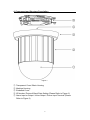
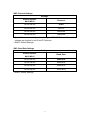
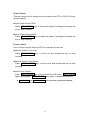
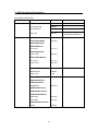
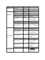
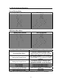
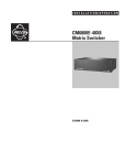
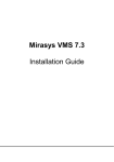
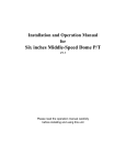
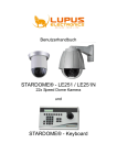
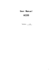
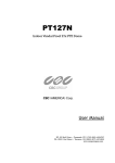
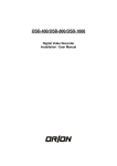
220X Color Speed Dome Camera
Manual
Contents
1. SYMBOL DESCRIPTION............................................................................ 2
2. FEATURES ................................................................................................. 3
3. SPECIFICATIONS ...................................................................................... 4
4. COMPONENT AND STRUCTURE DESCRIPTION .................................... 6
5. CAMERA SETTING .................................................................................... 7
6. INSTALLATION ......................................................................................... 10
7. SYSTEM ASSEMBLY ................................................................................11
8. OPERATION ............................................................................................. 13
9. OSD OPERATIONAL DESCRIPTION....................................................... 20
10. QUICK OPERATIONAL REFERENCE TABLE ....................................... 22
11. PELCO KEYBOARD OPERATION ......................................................... 23
12. APPENDIX .............................................................................................. 24
13. ACCESSORY.......................................................................................... 25
2004/09/09, Ver.: 0.1, P/N: 040072/2
1
1. Symbol Description
1. Function keys are shown by, framed capital boldface print letters.
Example:
ENTER ,
AUTO FOCUS , etc.
2. Function key “+” indicates the order sequence.
Example: 2
“ 8 ”, and then
⎡
3. ⎢
⎣
8 + ENTER
ENTER .
meaning, press the function key “ 2 “,
⎤
⎥ Indicate messages from the device and is shown
⎦
on the control keyboard LCD display.
DEVICE 001 : _
4. “n” indicates the ID number of the nth device (ID numbers ranges from
001~127).
2
2. Features
● Speedy response with 22x continuous auto-focus zoom lens and 10x
Electronic Zoom.
● Auto Iris and Manual Iris Control.
● Advanced DSP Camera, including Auto White Balance, Backlight
Compensation and Auto Iris Control.
● 360° Continuous Pan Rotation.
● 128 Preset Points Setup.
● Auto pan at pre-set point.
● Pan Speed up to 300°/Sec and Tilt Speed up to 200°/Sec.
● Horizontal Rotation of 180°.
● Built in 6 Alarm Inputs and one Relay Output.
● Two types of Alarm out signal are provided: NO and NC.
● Remote Control via RS-485.
● Connects up to 127 Speed Dome Cameras.
● Supports PELCO Protocol (D and P Protocol).
● PC control software is applicable.
● 12VDC Power Input (AC100~240V, 50Hz or 60Hz).
● Suitable for installation on different occasions; can be installed outside
(with outdoor dome housing), flush mount on a ceiling or in the ceiling
with only the dome showing.
3
3. Specifications
Manual Operation: Horizontal Rotational Speed
: Vertical Rotational Speed
Manual call on preset points: horizontal Rotational Speed
Vertical Rotation Speed
Preset Points Retention period
1°~150° Per Sec.
1°~100° Per Sec.
1°~300° Per Sec.
1°~200° Per Sec.
0~128 Sec.
Horizontal rotation of 180° single bond
Horizontal Rotational Angle
Vertical Rotational Angle
300° Per Sec.
360° Rotation
0°~90°
Precision Degree: Horizontal/ Vertical
Preset Points
Group setup
ID position setup
± 0.25°
128 Preset Points
6 Groups
1~127
Camera
Sensor Type
Total Pixels
1/4” CCD Image Sensor
811(H) X 508(V); 410k (NTSC)
795(H) X 596(V); 470k (PAL)
768(H) X 494(V); 380k (NTSC)
752(H) X 582(V); 440k (PAL)
2:1 Interlace
Effective Pixels
Scanning System
Horizontal Resolution
470(NTSC) TVL
470(PAL) TVL
NTSC: 1.0 Lux (30 IRE)
PAL: 1.0 Lux (210 mV)
More than 48dB
Internal Synchronization
Composite: 1.0 Vpp / 75Ω, BNC
Minimum Illumination
S/N Ratio
Synchronization
Video Output
22X optical zoom
Focal Distance
Iris
f = 3.9 ~ 85.8 mm (±5%)
F1.6 ~ 3.7 (±5%)
Focus Mode
Iris Control
Gain Control
Digital Zoom
Auto/ Manual
Auto/ Manual
Auto/ Manual
On/ Off
4
Electrical
DC Power Supply
100VAC ~ 240VAC
Power Input
Power Consumption
Controller Interface
Alarm Input
Alarm Output
Alarm Output Mode
12VDC
13W
RS-485
6 Alarm Inputs
1Set NC (Normal close)
1Set NO (Normal open)
0.5A 120Vac/1A 24Vdc
Lock onto the last Alarm Input
Environment
Operating Temperature
Relative Humidity
-10°C ~ 50°C
0% ~ 90%
Mechanism
Height
Diameter
Weight (Standard)
206.5mm
145mm
2.2Kg
5
4. Component and Structure Description
Figure 1.
①
②
③
④
⑤
Transparent Cover/ Black Housing
Machine Housing
Embellish Cover
ID Number/ Protocol/ Baud Rate Setting (Please Refer to Figure 2)
Alarm Input or Output / Video Output / Power Input Terminal (Please
Refer to Figure 3)
6
5. Camera Setting
Figure 2.
SW1: ID Number Setting
Connection of up to 127 Speed Dome
Cameras, each camera has its own ID
Number.
DIP Switch setting, shown below:
*
*
Setting 000, then the image display will show: DEVICE N/A.
Does not affect setup.
7
SW2: Protocol Settings
Settings
Switch Number
#4 #3 #2 #1
Protocol
Off Off Off Off
YOKO
Off Off Off On
PELCO
Off Off On Off
Reserved
Off Off On On
Reserved
* Speed Dome automatically detects the type of PELCO Protocol. No switch
settings are required to set D and P Protocols.
* BOLD: Default Settings.
SW3: Baud Rate Settings
Settings
Switch Number
#4 #3 #2 #1
Baud Rate
Off Off Off Off
9600 BPS
Off Off Off On
4800 BPS
Off Off On Off
2400 BPS
Off Off On On
19200 BPS
* BOLD: Default Settings
8
Terminal base Connection, Data Line, and Signal Line Regulation
Figure 3
1. Power Input Terminal - DC 12V Input and power consumption of 1.1A.
2. Video Output Terminal - Video Signal Output: CVBS 1. 0Vp-p 75Ω BNC.
3. The Speed Dome Camera is equipped with 6 external alarm triggering
input and 2 sets of alarm output (1 set NO and 1 set NC).
Alarm Input Voltage at 5.6Vmax and Alarm Output Specification: 0.5A
120VAC/ 1A 24VAC.
4. RS-485 Communication Control Input and Output connector
RS-485 Input Terminal has two terminal points (D+, D-), using the twisted
pair wire to connect onto the next Speed Dome Camera.
5. RJ-11 Input / Output Connector Control
The function is similar to RS-485 Communication Control Input and Output
connector. Using RJ-11 connector to interconnect.
9
6. Installation
Indoor Installation Structure Diagram (In-Ceiling and Flush Mounting)
In-Ceiling Mount
Flush Mount
Figure 4
10
7. System Assembly
Keyboard Controlling Application
User-friendly design with simple installation; it is able to control single or
multiple device surveillance system (the system supports connections of
numerous Speed Dome Cameras or PTZ Receivers).
It performs real-time operating environment connected through RS-485
terminal, for monitoring and connecting the Speed Dome Camera and the
P/T/Z Device from the control keyboard using twisted pair wiring connection.
Connecting Keyboard (YK8332)
. Connect the RS-485 serial port (terminal D +) from the control keyboard, to
the Speed Dome Camera RS-485 serial port (terminal D +). And connect
the RS-485 serial port (terminal D -) from the control keyboard, to the
Speed Dome Camera RS-485 serial port (terminal D -).
. The system supports connections of numerous Speed Dome Cameras or
PTZ Receivers, assigning a set of ID for setup and control.
. Before cascading the second device, connect DATA OUT from the first
device RS-485 serial port (terminal D+) onto DATA IN from the second
device RS-485 serial port (terminal D+), and connect the RS-485 serial
port (terminal D-) from the first device to the RS-485 serial port (terminal D-)
of the second device.
11
Connecting PELCO Keyboard (KBD200A / KBD300A)
. Connect the RS-422 serial port (terminal TX +) from the control keyboard, to
the Speed Dome Camera RS-485 serial port (terminal D +). And connect
the RS-422 serial port (terminal TX -) from the control keyboard, to the
Speed Dome Camera RS-485 serial port (terminal D -).
12
8. Operation
Speed Dome Start-up
After connecting all necessary cables, start-up the Speed Dome Camera.
Then, the Speed Dome Camera will return to the initial set position; meaning
that the Speed Dome Camera is in Stand by mode, ready for controller
keyboard connection control.
Connection Control of Remote Control
After connecting all necessary cables, startup the system connection, by
pressing SYS RESET key. The LCD then displays the following message:
⎡ SYSTEM LINKING?⎤
⎢
⎥ (the LED starts flashing to indicate their existence).
⎣
⎦
Press again SYS RESET key, the system connection will re-start, search
the system connection device and make sure that all the connected devices
are probably connected.
* When the LCD displays the following message:
⎡
⎢
⎣
DEVICE : XXX LOST ⎤
⎥ , it means that an error has been occurred.
PRESS SYS RESET
⎦
Please press
SYS RESET
key, after checking and sorting the circuit.
13
Manual Control (Up / Down / Left / Right / Speed)
Speed Dome Cameras or P/T/Z Receivers may be controlled manually, by
using the joystick (Up / Down / Left / Right / Speed).
►Joystick
The movement depends on the angel of the joystick:
Push the joystick up or down, the camera lens will move forward or
backward. Push the joystick left or right, the camera lens moves leftward or
rightward.
►Zoom Speed Setup
The LED lights up after pressing SPEED BY ZOOM key. Then, the
Pan/Tilt movement of the Dome will be proportional to the ratio.
* Movement slows down when zooming.
Switching Control of Speed Dome Camera
May select to connect a single Speed Dome Camera or 127 Speed Dome
Cameras at once. After completing installation (Setup, wiring and with the
power switched ON), select the ID number of the Speed Dome Camera to be
controlled.
► Use the number key + ENTER key
Pre-select the desired nth device, by pressing the number and ENTER
Key on the controller keyboard. Then, the LCD will display ID of the
device.
► Use the DOME SELECT KEY function of control keyboard.
DOME SELECT Key
DOME SELECT (
CH+
) the system automatically selects for the ID
number larger than the present ID number.
DOME SELECT (
CH-
) the system automatically selects for the ID
number smaller than the present ID number.
* After completing the change, the LCD will reflect the selected device ID and
when the action was failed or the selected device did not exist, no changes will
be shown by the LCD, it remains as original status.
14
Zoom Control
This item allows you to change the zoom ration from OFF to 220X (22 times
optical magnify).
►Lens Control-Zoom TELE
Press ZOOM TELE
key to stop zooming.
key, to narrow the angle of viewing and release the
►Lens Control-Zoom WIDE
Press ZOOM WIDE
key to stop zooming.
key, to widen the angle of viewing and release the
Focus Control
Focus Control may be done by AUTO or manually by the user.
►Manual Control- Focus Far
Press FOCUS FAR
focusing.
key, to focus far and release the key to stop
►Manual Control- Focus Near
Press FOCUS NEAR
focusing.
key, to focus near and release the key to stop
►Auto Focus Control
Press AUTO FOCUS key or the joystick, the LED of the AUTO FOCUS
lights up and press AUTO FOCUS key again, to disable the function.
*
FOCUS FAR
and
FOCUS NEAR
function has been started.
15
will not function, when AUTO FOCUS
Setting the Preset Points
Setting the preset point enables the Speed Dome Camera to have
preset points from 1~128. You may key in a number (1~128) and
press SET PRESET key, to store current position as preset. You may
also key in a number and run the preset point that you’ve just stored.
① Selecting a Speed Dome Camera
Press 1 key and the ENTER key, the LCD will display:
⎡ DEVICE 001 : _ ⎤
⎢
⎥ , it means that Speed Dome number “1” has been
⎣
⎦
selected.
Example: Select the 1st Speed dome Camera = 1 + ENTER
Select the 127th Speed dome Camera = 1
2
7 + ENTER
② Controlling the Joystick
The joystick may move the Speed Dome to that specific location.
③ Controlling the zoom ratio from 1X to 220X (22 times optical).
It is suggested when setting the preset points to manually adjust the iris,
to enable clarity and stability of the focal distance.
④ Key in a number (1~128) and press
SET PRESET
key, the LCD will
⎡ SAVE TO PRESET ⎤
⎥ , then press again SET PRESET key,
XXX ?
⎣
⎦
⎡ SAVE OK! ⎤
and when the display show: ⎢
⎥ , meaning that the setup has
⎣
⎦
display: ⎢
been completed.
* Repeat the steps ①~④ again, to set more preset points.
16
Call up the Preset Points
When the setup of the preset point has been completed, it may be called
upon.
►Enter the assigned preset number and press GO PRESET key, the
⎡GO PRESET : XXX ⎤
LCD will display: ⎢
⎥ , and the Speed Dome will move to
⎣
⎦
that specific preset point.
Example: 1st preset point = 1 + GO PRESET
128th preset point = 1
2
8 + GO PRESET
Change the Preset Point
To change the preset point, use the joystick to move the cursor to the preset
point setup selection and change to your desired settings.
Preset AUTO PAN
The Auto Pan has 1~32 setting points and you have to decide the pan
direction and the pan speed (total of 4 setting groups), every group has 32
setting points.
* The fifth group functions as a simple continuous rotational
manner; included are 1st, 2nd, and 3rd preset point.
* The sixth group functions as a simple continuous rotational
manner; included are 4th, 5th, and 6th preset points.
►Start-up Preset AUTO PAN
Under Control Mode (Assume
⎡
displays: ⎢
⎣
DEVICE 001 : _
device=1),
when
the
LCD
⎤
⎥ , key in the group number to be setup
⎦
(Assume group=1, then enter 1), then press
AUTO PAN key, the LED
DEVICE 001 :
⎡
⎤
of the AUTO PAN lights up, LCD displays ⎢
⎥,
⎣ AUTOPAN GROUP : 1 ⎦
meaning that the setup has been completed.
17
►Stop Preset AUTO PAN
Press AUTO PAN Key, the LED of the AUTO PAN goes off, meaning
that the function has been disabled.
►Control Under Preset AUTO PAN
When auto preset mode has been started, no other operations will function.
Unless, when auto-preset mode has been disabled.
Example: When device 2 runs preset AUTO PAN; then zoom control and
focus control will be temporary out of function. Until, when auto- preset
mode has been disabled.
Alarm Management
►Alarm Input
●The Speed Dome Camera is equipped with six alarm input connectors,
Alarm1~Alarm6, corresponds to both preset points and AUTO PAN Group.
Once the alarm signal is detected, the Speed Dome Camera will
automatically move to the preset point or Start-up AUTO PAN.
●For P/T/Z Receiver or other alarm devices. Please refer to its relevant
product manual for operation.
►Alarm Output
Alarm output is resulted when the alarm of the Speed Dome Camera has
been triggered (selectable: NO or NC mode).
►Alarm Mode Management
The Speed Dome Camera is set to lock on the last alarm input. Thus, once
the alarm signal is detected, the Speed Dome Camera will automatically
move to the preset point or Start-up AUTO PAN, triggering the alarm to
buzz,
EVENT RESET
LED will be lighted and the LCD will
⎡ DEVICE : XXX ⎤
display: ⎢
⎥ , informing the user that an alarm event has
⎣ ALARM INPUT ⎦
been detected.
18
● When the alarm of the Speed Dome Camera has been triggered under
Auto Pan ON mode, the Speed Dome Camera will rotate in 300° per
second to the preset correspondent point (Group AUTO PAN). When the
alarm of more than one device has been triggered continuously, then the
system will select to lock on controlling the last device triggered by the
alarm event.
● When the alarm of the Speed Dome Camera has been triggered under
Auto Pan OFF mode, the Speed Dome Camera will rotate in 300° per
second to the preset correspondent point (Group AUTO PAN).
● The buzzer does not dismiss automatically, the user has to press
EVENT RESET key, in order to stop the buzzer.
● When the Speed Dome Camera detects an alarm signal; the message
“ALARM” will be shown on the top right hand corner of the display. The
message does not dismiss automatically, but by making slight
movements with the joystick, clears away the message.
● Entered the Speed Dome Camera setup mode, straight after the alarm
event has been cleared, the Speed Dome Camera will recheck the alarm
status, when exiting the Speed Dome Camera setup mode.
19
9. OSD Operational Description
OSD TREE STRUCTURE
MAIN MENU
STATES SET UP
ITEM
SELECTION
ID DISPLAY
ON/OFF
FLIP FUNCTION
ON/OFF
TITLE DISPLAY
ON/OFF
TITLE SET
xxxxxxxx
CAMERA SET UP EXPOSURE
000~028
SHUTTER SPEED
EXPOSURE Auto
EXPOSURE Iris
Iris Level
074~179
EXPOSURE AGC
AGC Level
028~220
EXPOSURE Manual
Iris Level
074~179
AGC Level
028~220
BACKLIGHT
BACKLIGHT
ON/OFF
BLC Level
0~80
WBC MODE
WBC MODE Auto
WBC MODE Hue
000~099
MWB Data
WBC MODE Indoor
WBC MODE Outdoor
WBC MODE Manual
Red Data
000~255
Blue Data
000~255
WBC MODE Push Auto
ON/OFF
Setup
20
NOTES
Use number 0 as substitute
for capital letter alphabet O
MAIN MENU
IMAGE SET UP
ALARM SET UP
ITEM
SELECTION
NOTES
BRIGHTNESS
000~099
FLICKERLESS
ON/OFF
SHARPNESS
000~015
MIRROR
ON/OFF
COLOR
ON/OFF
ALARM PIN
001~006
Alarm Serial Number
ALARM SWITCH
ON/OFF
Alarm Switch
Execution Mode after Alarm
ALARM TYPE
GPO/RAP
GPO: GO POSITION
RAP: RUN AUTOPAN
AUTOPAN GROUP
001~004
PRESET POSITION
001~128
Preset Point Serial Number
Alarm retention period;
DWELL TIME (sec)
001~128
retention --- meaning forever
halt.
HOME SET UP
HOME FUNCTION
ON/OFF
Homing Function
PRESET POSITION
001~128
Select Homing Point
Homing Time, start counting
RETURN TIME (min)
001~030
from the instant when the
device stopped moving.
AUTOPAN 005、006 as
AUTOPAN SET UP AUTOPAN GROUP
001~004
simple manner, it does not
need setup.
AUTOPAN INDEX
001~032
Notation --- meaning to
PRESET POSITION
001~128
ignore the points after
AUTOPAN POINT
Speed to the next point:
AUTOPAN SPEED
001~015
001=Slowest and
015=Fastest
DWELL TIME (sec)
001~128
Press
ENTER
key, to
display Load default and
LOAD DEFAULT
press it again to confirm.
21
10. Quick Operational Reference Table
Functions
Restart System Connection
Upward rotation
Method of Operation
SYS RESET
(SYS RESET LED ON)
Push the joystick forward
Downward rotation Push the joystick backward
P/T/Z Control Leftward rotation
Rightward
rotation
Select Dome Camera
Lens Control
Manual Control
Push the joystick leftward
Push the joystick rightward
No. Key+ ENTER
ZOOM TELE
or
or
CH+ 、 CH-
ZOOM WIDE
FOCUS FAR
(AUTO FOCUS LED OFF)
FOCUS NEAR
(AUTO FOCUS LED OFF)
Auto Focus
AUTO FOCUS
(AUTO FOCUS LED ON)
Speed By Zoom
SPEED BY ZOOM
(SPEED BY ZOOM LED ON)
Brightness Control
.
BRIGHTNESS +
or
BRIGHTNESS -
Chose to Select the Preset
Points
No. Key + GO PRESET
(128 Preset Points)
Start-up the Preset Mode
No. Key (Group No.)+ AUTO PAN
(AUTO PAN LED ON)
Stop the Preset Mode
AUTO PAN or Push the joystick
(AUTO PAN LED OFF)
Disable the Alarm
EVENT RESET
(EVENT RESET LED OFF)
Relay Switch
RELAY1
RELAY2
RELAY3
(LED light ON meaning LED ON and
vise versa.)
* The following function: RELAY 1 , RELAY 2 and RELAY 3 ; does not
work on Speed Dome Camera.
* The following function: BRIGHTNESS + and BRIGHTNESS – ; only works
under Auto Exposure, IRIS Manual or AGC Manual.
22
11. PELCO Keyboard Operation
Normal Display Mode
Speed Dome Function
Focus Near
Focus Far
Brightness +
Brightness Pan Left
Pan Right
Tilt Up
Tilt Down
Zoom Tele
Zoom Wide
PELCO Keyboard
NEAR
FAR
OPEN
CLOSE
Move Joystick Left
Move Joystick Right
Move Joystick Up
Move Joystick Down
Twist Joystick clockwise
Twist Joystick counterclockwise
OSD Setup Menu Mode
Speed Dome Function
Cursor Up
Cursor Down
Menu Enter
Menu Exit
Decrease (-)
Increase (+)
None
None
None
None
Speed Dome Function
Accessing Main Menu
Call up the Preset Points
Setting the Preset Points
AUTO SCAN
STOP SCAN
Call up Preset AUTO PAN
Stop Preset AUTO PAN
PELCO Keyboard
NEAR
FAR
OPEN
CLOSE
Move Joystick Left
Move Joystick Right
Move Joystick Up
Move Joystick Down
Twist Joystick clockwise
Twist Joystick counterclockwise
PELCO Keyboard Operation
Enter 95; Hold the PRESET key
(approximately five seconds) until the
main menu appears on the screen.
Enter preset number (1~32, 35~82) and
press PRESET to put camera in preset
position.
To program, position camera, enter
desired preset number (1~32,35~82), and
hold down PRESET for two seconds.
Enter 99 and press PRESET
Enter 96 and press PRESET
Enter group number (1~6) and press
PATTERN
Press ACK
Please refer to PELCO Keyboard (KBD200A/ KBD300A) manual for more information.
23
12. Appendix
Trouble shooting
1. Speed Dome Camera switched OFF
1-1 Check whether the power supply is 12V.
1-2 Check whether the fuse has been burned.
1-3 Check whether the 20PIN of the camera foot has fallen off.
2. No video image on the monitor
2-1 Check whether the video signal line of the Speed Dome Camera
is connected properly.
2-2 Check whether video signal has been disconnected.
2-3 Check whether the video signal line of the monitor is connected
properly.
2-4 Check whether the 20PIN of the Speed Dome Camera has fallen
off.
3. Unable to control the Speed Dome Camera
3-1 Check whether the ID position is correct.
3-2 Check whether the communication control output or input
terminal RS-485 In / Out JACK of the Speed Dome Camera and
the control wire are properly connected.
3-3 Check whether the communication control terminal RS-485
JACK and control wire is properly connected.
3-4 Please disables Auto Pan function.
3-5 Check whether the Speed Dome Camera is in the act of
processing the alarm due to alarm interchange action. For this
eliminates all functions.
4. Speed Dome Camera Out of Focus
4-1 Please wipe with cotton-cloth when there are dusts on the
transparent cover or on the Speed Dome Camera Housing.
Please contact your local dealer for any other problems unmentioned above.
24
13. Accessory
1. DC adapter x1
2. Power Line x1
3. Power connector x1
4. 6P4C - 3M/ white double headed phone line x1
5. M3x4 screw x6
(In-Ceiling/ Flush Mount)
6. In-Ceiling Fixed Ring x1
(In-Ceiling Mount)
7. 35mm pillar of copper x3
(In-Ceiling Mount)
8. 40mm pillar of copper x3
(In-Ceiling Mount)
9. 45mm pillar of copper x3
(In-Ceiling Mount)
10. Embellished flush cover x1
(Flush Mount)
11. Embellished In-Ceiling Cover x1
(In-Ceiling Mount)
12. User’s Manual x1
25