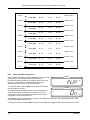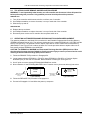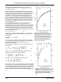
1
User’s Manual Model 330 Autotuning Temperature Controller Includes Coverage For: Model 330-1X – Silicon Diode Model 330-2X – Platinum Resistor Model 330-3X – GaAlAs Diode Model 330-4X – Thermocouple Model 330-5X – Thermocouple Lake Shore Cryotronics, Inc. 575 McCorkle Blvd. Westerville, Ohio 43082-8888 USA E-Mail Addresses: [email protected] [email protected] Visit Our Website: www.lakeshore.com Fax: (614) 891-1392 Telephone: (614) 891-2243 Methods and apparatus disclosed and described herein have been developed solely on company funds of Lake Shore Cryotronics, Inc. No government or other contractual support or relationship whatsoever has existed which in any way affects or mitigates proprietary rights of Lake Shore Cryotronics, Inc. in these developments. Methods and apparatus disclosed herein may be subject to U.S. Patents existing or applied for. Lake Shore Cryotronics, Inc. reserves the right to add, improve, modify, or withdraw functions, design modifications, or products at any time without notice. Lake Shore shall not be liable for errors contained herein or for incidental or consequential damages in connection with furnishing, performance, or use of this material. Rev. 1.3 P/N 119-009 15 November 2000 Lake Shore Model 330 Autotuning Temperature Controller User’s Manual LIMITED WARRANTY Lake Shore Cryotronics, Inc. (henceforth Lake Shore), the manufacturer, warrants this product to be free from defects in material or workmanship for a period of 12 months from the date of shipment. During the warranty period, under authorized return of instruments or component parts to Lake Shore freight prepaid, the company will repair, or at its option replace, any part found to be defective in material or workmanship, without charge to the owner for parts, service labor or associated customary return shipping cost. Replacement or repaired parts will be warranted for only the unexpired portion of the original warranty or 90 days (whichever is greater). All products are thoroughly tested and calibrated to published specifications prior to shipment. Calibration Certifications are offered for 6 month periods only. Where such documentation must be updated, a re-certification service is offered by Lake Shore at a reasonable cost. LIMITATION OF WARRANTY This warranty does not apply to defects resulting from improper installation, product modifications made by others without Lake Shore’s express written consent, or from misuse of any product or part. This warranty also does not apply to fuses, software, non-rechargeable batteries, or problems arising from normal wear or failure to follow instructions. This warranty is in lieu of any other warranties, expressed or implied, including merchantability, or fitness for a particular purpose, which are expressly excluded. The owner agrees that Lake Shore's liability with respect to this product shall be set forth in this warranty, and incidental or consequential damages are expressly excluded. CERTIFICATION Lake Shore certifies that this product has been inspected and tested in accordance with its published specifications and that this product met its published specifications at the time of shipment. The accuracy and calibration of this product at the time of shipment are traceable to the United States National Institute of Standards and Technology (NIST); formerly known as the National Bureau of Standards (NBS). FIRMWARE LIMITATIONS Lake Shore has worked to ensure that the Model 330 firmware is as free of errors as possible, and that the results you obtain from the instrument are accurate and reliable. However, as with any computer-based software, the possibility of errors exists. In any important research, as when using any laboratory equipment, results should be carefully examined and rechecked before final conclusions are drawn. Neither Lake Shore nor anyone else involved in the creation or production of this firmware can pay for loss of time, inconvenience, loss of use of the product, or property damage caused by this product or its failure to work, or any other incidental or consequential damages. Use of our product implies that you understand the Lake Shore license agreement and statement of limited warranty. FIRMWARE LICENSE AGREEMENT The firmware in this instrument is protected by United States copyright law and international treaty provisions. To maintain the warranty, the code contained in the firmware must not be modified. Any changes made to the code is at the user’s risk. Lake Shore will assume no responsibility for damage or errors incurred as result of any changes made to the firmware. Under the terms of this agreement you may only use the Model 330 firmware as physically installed in the instrument. Archival copies are strictly forbidden. You may not decompile, disassemble, or reverse engineer the firmware. If you suspect there are problems with the firmware, return the instrument to Lake Shore for repair under the terms of the Limited Warranty specified above. Any unauthorized duplication or use of the Model 330 firmware in whole or in part, in print, or in any other storage and retrieval system is forbidden. TRADEMARK ACKNOWLEDGMENT Many manufacturers and sellers claim designations used to distinguish their products as trademarks. Where those designations appear in this manual and Lake Shore was aware of a trademark claim, they appear with initial capital ® letters and the ™ or symbol. Apiezon® is a trademark of Biddle Instruments. CalCurve™, Carbon-Glass™, Cernox™, Duo-Twist™, Quad-Lead™, Quad-Twist™, and SoftCal™ are trademarks of Lake Shore Cryotronics, Inc. Chromel™ and Alumel™ are trademarks of Hoskins Manufacturing Company. Cryo-Gloves® is a trademark of Tempshield. Formvar™ is a trademark of Monsanto Chemical Company. MS-DOS® and Windows/95/98/NT/2000® are trademarks of Microsoft Corporation. NI-488.2™ is a trademark of National Instruments. Stycast® is a trademark of Emerson & Cuming. Teflon® is a trademark of DuPont De Nemours. Copyright © 1994 – 2000 by Lake Shore Cryotronics, Inc. All rights reserved. No portion of this manual may be reproduced, stored in a retrieval system, or transmitted, in any form or by any means, electronic, mechanical, photocopying, recording, or otherwise, without the express written permission of Lake Shore. A Lake Shore Model 330 Autotuning Temperature Controller User’s Manual Declaration of Conformity We: Lake Shore Cryotronics, Inc. 575 McCorkle Blvd. Westerville, OH 43082-8888 USA hereby declare that the equipment specified conforms to the following Directives and Standards: Application of Council directives: Standard to which Conformity is declared: 73/23/EEC 89/336/EEC EN55022 EN50082-1 EN61010-1 Model Number: 330 Signature Date John M. Swartz Printed Name President Position B Lake Shore Model 330 Autotuning Temperature Controller User’s Manual Electromagnetic Compatibility (EMC) for the Model 330 Temperature Controller Electromagnetic Compatibility (EMC) of electronic equipment is a growing concern worldwide. Emissions of and immunity to electromagnetic interference is now part of the design and manufacture of most electronics. To qualify for the CE mark, the Model 330 meets or exceeds the generic requirements of the European EMC directive 89/336/EEC. The instrument was tested under normal operating conditions with sensor and interface cables attached. If the installation and operating instructions in the User's Manual are followed, there should be no degradation in EMC performance. Pay special attention to instrument cabling. Improperly installed cabling may defeat even the best EMC protection. For the best performance from any precision instrument, follow the grounding and shielding instructions in the User's Manual. In addition, the installer of the Model 330 should consider the following: C • Leave no unused or unterminated cables attached to the instrument. • Make cable runs as short and direct as possible. • Do not tightly bundle cables that carry different types of signals. • Add the clamp-on ferrite filter (part number 109-053) included with the connector kit to the serial interface cable near the instrument rear panel when that interface is used. Lake Shore Model 330 Autotuning Temperature Controller User’s Manual TABLE OF CONTENTS Chapter/Paragraph Title Page 1 INTRODUCTION ....................................................................................................................................1-1 1.0 General................................................................................................................................1-1 1.1 Model 330 Temperature Controller Description ..................................................................1-2 1.2 Control Fundamentals and Autotune...................................................................................1-5 1.3 Precision Calibration Options ..............................................................................................1-6 1.4 Electrostatic Discharge........................................................................................................1-6 1.4.1 Identification of Electrostatic Discharge Sensitive Components ......................................1-6 1.4.2 Handling Electrostatic Discharge Sensitive Components ................................................1-6 1.5 Handling Liquid Helium and Liquid Nitrogen........................................................................1-7 1.5.1 Handling Cryogenic Storage Dewars ...............................................................................1-7 1.5.2 Liquid Helium and Nitrogen Safety Precautions...............................................................1-7 1.5.3 Recommended First Aid...................................................................................................1-7 1.6 Safety Summary ..................................................................................................................1-8 1.7 Safety Symbols....................................................................................................................1-8 2 INSTALLATION ......................................................................................................................................2-1 2.0 General................................................................................................................................2-1 2.1 Inspection and Unpacking ...................................................................................................2-1 2.2 Repackaging For Shipment .................................................................................................2-1 2.3 Definition of Rear Panel Connections..................................................................................2-2 2.4 Sensor Input Settings ..........................................................................................................2-3 2.5 Grounding and Shielding .....................................................................................................2-3 2.6 Sensor Installation ...............................................................................................................2-4 2.6.1 Diode (Model 330-1X) and Platinum (Model 330-2X) Connections .................................2-4 2.6.1.1 Two-Lead Versus Four-Lead Measurements ...............................................................2-4 2.6.1.2 Heat Sinking Sensor Leads ..........................................................................................2-5 2.6.1.3 Sensor Mounting ...........................................................................................................2-5 2.6.1.4 Measurement Errors Due to AC Noise .........................................................................2-6 2.6.2 Thermocouple (Model 330-4X) Connections ...................................................................2-6 2.6.2.1 Thermocouple Compensation.......................................................................................2-6 2.6.2.2 Thermocouple Wire Types at Cryogenic Temperatures ...............................................2-6 2.6.3 Sensor Input Error Messages ..........................................................................................2-7 2.7 Sensor Curve Selection.......................................................................................................2-7 2.8 Precision Calibration Option ................................................................................................2-8 2.9 Heater Setup .......................................................................................................................2-9 2.10 Rack Mounting.....................................................................................................................2-9 2.11 Power Up .............................................................................................................................2-9 2.11.1 Power Up Sequence ........................................................................................................2-9 2.11.2 Power Up (PUP) Configuration ......................................................................................2-10 2.11.3 Power Up Errors.............................................................................................................2-10 3 OPERATION...........................................................................................................................................3-1 3.0 General................................................................................................................................3-1 3.1 Definition of Front Panel Controls........................................................................................3-1 3.1.1 Front Panel Keypad Definitions ........................................................................................3-1 3.1.2 Front Panel LED Display ..................................................................................................3-2 3.2 Thermometry Functions ......................................................................................................3-2 3.2.1 Input Type ........................................................................................................................3-3 3.2.2 Channel ............................................................................................................................3-3 3.2.3 Units .................................................................................................................................3-3 3.2.4 Thermocouple Temperature Compensation (Model 330-4X Only) ..................................3-3 3.2.5 Display Filter.....................................................................................................................3-4 3.2.6 Curve................................................................................................................................3-4 Table of Contents i Lake Shore Model 330 Autotuning Temperature Controller User’s Manual Chapter/Paragraph 3.2.7 3.2.7.1 3.2.7.2 3.2.7.3 3.3 3.3.1 3.3.2 3.3.2.1 3.3.2.2 3.3.3 3.3.4 3.3.4.1 3.3.4.2 3.3.4.3 3.3.4.4 3.3.5 3.3.5.1 3.3.5.2 3.3.5.3 3.3.5.4 3.3.6 3.4 3.4.1 3.4.2 3.4.3 3.4.4 3.4.5 3.5 3.5.1 3.5.2 3.5.3 3.5.4 3.5.5 3.5.6 4 ii Title Page SoftCal ............................................................................................................................. 3-5 SoftCal Errors ............................................................................................................... 3-5 Customer-Performed SoftCal ....................................................................................... 3-6 Entering Voltage Values from a Lake Shore SoftCal Report........................................ 3-6 Control Functions ................................................................................................................ 3-8 Heater .............................................................................................................................. 3-8 Setpoint and Control ........................................................................................................ 3-8 Voltage Resolution (Models 321-1X, -3X, & -4X Only)................................................. 3-9 Resistance Resolution (Model 330-2X Only)................................................................ 3-9 Ramp ............................................................................................................................... 3-9 AutoTune ......................................................................................................................... 3-9 Initial Values of PID Parameters in Autotuning Mode................................................. 3-10 Minimum Overshoot ................................................................................................... 3-10 Minimum Time To Setpoint ........................................................................................ 3-10 Gain Only.................................................................................................................... 3-10 Manual Control Settings (PID) ....................................................................................... 3-10 Setting Gain (Proportional) ......................................................................................... 3-10 Setting Reset (Integral)............................................................................................... 3-10 Setting Rate (Derivative)............................................................................................. 3-11 Effect of Temperature on Tuning Parameters............................................................ 3-11 Zone Setting................................................................................................................... 3-11 Interface and Miscellaneous Functions............................................................................. 3-13 Baud............................................................................................................................... 3-13 Address.......................................................................................................................... 3-13 Local .............................................................................................................................. 3-13 Instrument Reset and Factory Default Settings ............................................................. 3-13 Power Up (PUP) Configuration ...................................................................................... 3-14 Thermocouple Controller Operation (Model 330-4X Only) ............................................... 3-15 Sensor Attachment ........................................................................................................ 3-15 Thermocouple Curve Selection ..................................................................................... 3-15 Thermocouple Compensation From Front Panel .......................................................... 3-15 Thermocouple Compensation From Remote Interface ................................................. 3-15 Internal Offset Adjustment ............................................................................................. 3-15 Curve Format................................................................................................................. 3-15 REMOTE OPERATION.......................................................................................................................... 4-1 4.0 General ............................................................................................................................... 4-1 4.1 IEEE-488 Interface.............................................................................................................. 4-1 4.1.1 IEEE-488 Interface Settings ............................................................................................ 4-1 4.1.2 IEEE-488 Command Structure ........................................................................................ 4-1 4.1.2.1 Bus Control Commands ............................................................................................... 4-2 4.1.2.2 Common Commands ................................................................................................... 4-2 4.1.2.3 Interface and Device Specific Commands ................................................................... 4-2 4.1.3 Status Registers .............................................................................................................. 4-2 4.1.3.1 Status Byte Register and Service Request Enable Register ........................................ 4-2 4.1.3.2 Standard Event Status Register and Standard Event Enable Register ........................ 4-3 4.1.4 Example IEEE Setup and Program ................................................................................. 4-4 4.1.4.1 GPIB Board Installation ................................................................................................ 4-4 4.1.4.2 Run the Example QuickBasic Program ........................................................................ 4-4 4.1.5 Notes On Using the IEEE Interface ................................................................................. 4-4 4.2 Serial I/O Interface .............................................................................................................. 4-7 4.2.1 Serial Interface Hardware Configuration.......................................................................... 4-8 4.2.2 Sample BASIC Serial Interface Program......................................................................... 4-8 4.2.3 Notes On Using The Serial Interface ............................................................................... 4-8 Table of Contents Lake Shore Model 330 Autotuning Temperature Controller User’s Manual Chapter/Paragraph 4.3 4.3.1 4.3.2 4.3.3 4.3.4 4.3.5 4.3.6 4.4 Title Page IEEE-488/Serial Interface Command Summary................................................................4-10 Command List Structure ................................................................................................4-10 Common Commands .....................................................................................................4-11 Interface Commands......................................................................................................4-13 Display Commands ........................................................................................................4-14 Control Process Commands ..........................................................................................4-16 Curve Commands ..........................................................................................................4-19 User Curve Loading Program............................................................................................4-23 5 SERVICE AND CALIBRATION ..............................................................................................................5-1 5.0 General................................................................................................................................5-1 5.1 General Maintenance Precautions ......................................................................................5-1 5.2 Changing Power Setting and Fuse Rating...........................................................................5-1 5.3 Rear Panel Connector Definitions .......................................................................................5-2 5.4 IEEE-488 Interface Connector.............................................................................................5-3 5.5 Optional Serial Interface Cable and Adapters .....................................................................5-4 5.6 Top of Enclosure Remove and Replace Procedure ............................................................5-5 5.7 Operating Software EPROM and Precision Option NOVRAM Replacement......................5-5 5.8 Error Messages ...................................................................................................................5-6 5.9 Changing Sensor Input Type ...............................................................................................5-6 5.10 Calibration (Diode/Platinum Input).......................................................................................5-7 5.11 Model 330-4X (Thermocouple) Calibration .........................................................................5-9 5.12 Model 330-4X (Thermocouple) Internal Offset Adjustment.................................................5-9 6 OPTIONS AND ACCESSORIES ............................................................................................................6-1 6.0 General................................................................................................................................6-1 6.1 Models .................................................................................................................................6-1 6.2 Options ................................................................................................................................6-1 6.2.1 Model 330-51 Option........................................................................................................6-2 6.3 Accessories .........................................................................................................................6-3 APPENDIX A – CURVE TABLES ................................................................................................................ A-1 APPENDIX B – APPLICATION NOTES ...................................................................................................... B-1 B1.0 General............................................................................................................................... B-1 ALPHABETICAL INDEX ......................................................................................................................INDEX-1 Table of Contents iii Lake Shore Model 330 Autotuning Temperature Controller User’s Manual LIST OF ILLUSTRATIONS Figure No. Title Page 1-1 1-2 1-3 Model 330 Temperature Controller Front Panel .............................................................................. 1-2 Model 330 Block Diagram ................................................................................................................ 1-5 Cryogenic Storage Dewar ................................................................................................................ 1-7 2-1 2-2 Typical Model 330 Rear Panel ......................................................................................................... 2-2 Heater Jumper (JMP9)..................................................................................................................... 2-9 3-1 3-2 3-3 3-4 Model 330 Front Panel..................................................................................................................... 3-1 Definition of Front Panel LED Display.............................................................................................. 3-2 Sensor Calibrations and Precision Options...................................................................................... 3-7 Record of Zone Settings ................................................................................................................ 3-12 4-1 4-2 Typical National Instruments GPIB Configuration from IBCONF.EXE............................................. 4-6 Optional Serial Interface Connections.............................................................................................. 4-7 5-1 5-2 5-3 5-4 5-5 5-6 5-7 5-8 5-9 Power Fuse Access ......................................................................................................................... 5-1 SERIAL I/O RJ-11 Rear Panel Connector Details ........................................................................... 5-2 SENSOR CHANNEL A and B Rear Panel Connector Details ......................................................... 5-2 HEATER OUTPUT Rear Panel Connector Details .......................................................................... 5-2 IEEE-488 Rear Panel Connector Details ......................................................................................... 5-3 Model 2001 RJ-11 Cable Assembly Wiring Details ......................................................................... 5-4 Model 2003 RJ-11 to DE-9 Adapter Wiring Details.......................................................................... 5-4 Model 2002 RJ-11 to DB-25 Adapter Wiring Details........................................................................ 5-4 Typical Model 330 PCB Layout ........................................................................................................ 5-8 6-1 6-2 6-3 6-4 6-5 Model 2001 RJ-11 Cable Assembly................................................................................................. 6-4 Model 2002 RJ-11 to DB-25 Adapter ............................................................................................... 6-4 Model 2003 RJ-11 to DE-9 Adapter ................................................................................................. 6-4 Model RM-3H1(-H) Rack-Mount Kit ................................................................................................. 6-5 Model RM-3H2(-H) Dual Rack-Mount Kit......................................................................................... 6-6 LIST OF TABLES Table No. Title Page 1-1 1-2 Electronic Information for Various Sensors and Temperature Ranges.......................................... 1-3 Model 330 Specifications................................................................................................................ 1-4 2-1 2-2 2-3 Sensor Input Setup......................................................................................................................... 2-3 Diode or Platinum Input Connections ............................................................................................. 2-4 Sensor Curves (Abbreviated) ......................................................................................................... 2-8 3-1 Sensor Curves (Complete list with write-in area) ........................................................................... 3-4 4-1 4-2 4-3 Sample BASIC IEEE-488 Interface Program ................................................................................. 4-5 Serial Interface Parameters............................................................................................................ 4-8 Sample BASIC Serial Interface Program ....................................................................................... 4-9 5-1 Sensor Input Setup......................................................................................................................... 5-6 A-1 A-2 A-3 Standard Diode and Platinum Curves ............................................................................................ A-1 Thermocouple Curves – Chromel Versus Gold/Iron ...................................................................... A-2 Thermocouple Curves – Chromel Versus Copper ......................................................................... A-2 iv Table of Contents Lake Shore Model 330 Autotuning Temperature Controller User’s Manual CHAPTER 1 INTRODUCTION 1.0 GENERAL Lake Shore Cryotronics, Inc. designed and manufactures the Model 330 Autotuning Temperature Controller in the United States of America. It is a microprocessor-based instrument with digital control of a variable current output. Features include: • • • • • Four Primary Sensor Configurations (can be ordered in any combination): – Silicon Diode Model 330-1X – Platinum Resistor 100 Ω Model 330-2X – GaAlAs Diode Model 330-3X – Thermocouple Model 330-4X Thermometry: – Dual Sensor Inputs – Isolated current sources allow true 4-wire sensor readings. – Isolated digital and analog power supplies improve sensor readings and quiet heater output – Nonvolatile Memory Space store up to 21 sensor calibration curves – SoftCal™ improves system accuracy with simple one to three point calibrations by user Five Tuning Modes: – Autotuning P – Autotuning PI – Autotuning PID – Manual – Zone (Ten Temperature Zones) Control: – Control Stability to ±2.5 mK – Three Term PID Control Loop – 25 or 50 Watt (Maximum), with 2 lower power ranges in decade steps – Setpoint Ramping Interface: – 4.5-Digit LED Display for High Visibility – Dual Display of Sensor Temperature in K, °C, or sensor units in volts, ohms – Setpoint Display – Continuous Display of Heater Output in 5% increments of the heater range selected – IEEE-488 and Serial Interface (RS-232C Electrical Format) We welcome comments concerning this manual. Although we try to keep it free from errors, some may occur. When reporting specific problems, describe it briefly and include the applicable paragraph, figure, table, and page number. Send comments to Lake Shore Cryotronics, Attn: Technical Publications, 575 McCorkle Blvd., Westerville, Ohio 43082-8888. This manual is subject to change without notice. Due to our commitment to continuous product improvement, we may modify the Model 330 software with time. Some changes result from Customer feedback regarding operation on various cryogenic systems. Please contact us with any observations or suggestions regarding the use of this controller. Also, please return warranty card to ensure receipt of software updates. Introduction 1-1 Lake Shore Model 330 Autotuning Temperature Controller User’s Manual 1.1 MODEL 330 TEMPERATURE CONTROLLER DESCRIPTION The Model 330 is a microcontroller-based Autotuning temperature controller. There are four primary sensor input types: the Model 330-1X for Silicon Diode Temperature Sensors, the Model 330-2X for Platinum Resistors, the Model 330-3X for Gallium Aluminum Arsenide Diodes, and the Model 330-4X for Thermocouples. The Model 330 accommodates these commonly used cryogenic temperature sensors in any combination (thermocouples optional). They are field selectable, without calibration (except for thermocouples, which are factory-installed when ordered). The Model 330 bright red dual LED display shows data from both sensors, or one sensor and the setpoint. It displays temperature in K, °C, or sensor units in volts (V), millivolts (mV), or ohms (Ω). Heater output current always displays on a separate bar graph. The full function keypad makes the Model 330 easy to operate. Precision thermometry is necessary for stable, accurate control, and the Model 330 analog design provides stable and repeatable measurements. Current source isolation allows for a true four-lead measurement of the sensor signal. A high-resolution A/D converter digitizes the signal for use in thermometry, control, and Autotuning. Enhance Model 330 thermometry accuracy with a Lake Shore calibrated sensor and 8000 Series Precision Calibration Option, or with SoftCal. Model 330 control software compares the measured control sensor value to the desired control setpoint and minimizes the difference with a three term (PID) function. Enter control parameters in any one of five tuning modes: Autotuning P, Autotuning PI, Autotuning PID, Zone, and Manual. Autotuning utilizes information gathered during setpoint changes to automatically optimize control parameters. Program up to 10 custom temperature zones so the controller automatically uses pre-programmed PID settings and heater ranges (computer interface required). Set the rate at which the ramp setpoint increases or decreases when it is changed. Combine this setting with the zone feature to ramp through all 10 zones from 2 K to room temperature with only a setpoint change. The controller changes PID and heater range settings as the setpoint passes through different zones. Two heater settings provide 25 W or 50 W maximum and accommodate a variety of cryogenic systems. The Model 330 power output is a quiet, variable DC current for as little noise coupling as possible between the heater and experiment. If lower power is required, two lower ranges are available with either of the settings. Both IEEE-488 and Serial Interfaces provide remote access to data from the Model 330 and allows setting of most front panel functions. C-330-1-1 Figure 1-1. Model 330 Temperature Controller Front Panel 1-2 Introduction Lake Shore Model 330 Autotuning Temperature Controller User’s Manual Table 1-1. Electronic Information for Various Sensors and Temperature Ranges Suffix 1 2 3 4* Sensor Type Silicon Diode 100Ω Platinum RTD GaAlAs Diode Thermocouple Sensor Temperature Coefficient Negative Positive Negative Positive Sensor Units Volts (V) Ohms (Ω) Volts (V) Millivolts (mV) Input Range 0 – 2.5 V 0 – 300 Ω 0–6 V ±15 mV Sensor Excitation 10 µA ±0.1% constant current 1 mA ±0.01% constant current 10 µA ±0.1% constant current N/A The following specifications reflect operational characteristics with the specified Lake Shore Sensor. Example Lake Shore Sensor DT-470-C0 PT-103 TG-120P with 1.4HS calibration with 1.4L calibration with 14J calibration Ch-AuFe 0.07% Sensor Temp. Range 1.4 – 475 K 30 – 800 K 1.4 – 325 K 1.4 – 325 K Standard Sensor Curve LSCI Curve 10 DIN 43760 Needs Calibration and 8001 Precision Option NBS/NIST generated Typical Sensor Sensitivity –30 mV/K at 4.2 K –1.9 mV/K at 77 K –2.4 mV/K at 300 K –2.2 mV/K at 475 K 0.19 Ω /K at 30 K 0.42 Ω /K at 77 K 0.39 Ω /K at 300 K 0.33 Ω /K at 800 K –180 mV/K at 4.2 K 16 µV/K at 4.2 K –1.25 mV/K at 77 K 20 µV/K at 300 K –2.75 mV/K at 300 K 5mΩ 26 mK at 30 K 12 mK at 77 K 13 mK at 300 K 15 mK at 800 K 0.09 mV 0.5 mK at 4.2 K 72 mK at 77 K 32 mK at 300 K 0.45 µV 30 mK at 4.2 K 22 mK at 300 K 0.01 Ω to 0.1 Ω 0.1 mV to 1 mV 1 µV Measurement Resolution: Sensor Units 0.04 mV Temperature 1.3 mK at 4.2 K Equivalence 21 mK at 77 K 16 mK at 300 K 18 mK at 475 K Sensor Units Display Resolution 0.1 mV to 1 mV Measurement Accuracy ±125 µV ±0.015% RDG ±12 m Ω ±0.04% RDG ±200 µV ±0.035% ±1.5 µV + 0.1% RDG Temperature ±50 mK at 4.2 K Accuracy with ±120 mK at 77 K Calibrated Sensor and 8001 Precision Option ±45 mK at 30K ±62 mK at 77K ±80 mK at 300 K ±75 mK at 475 K ±40 mK at 4.2 K ±350 mK at 77 K ±105 mK at 300K ±235 mK at 800K ±406 mK at 4.2K † ±110 mK at 300K ±150 mK at 300 K Measurement Temperature Coefficient Sensor Units ±0.002% (%RDG/°C Ambient) ±0.004% ±0.006% ±0.01% ±15 mK at 30 K ±15 mK at 77 K ±15 mK at 300 K ±25 mK at 800 K ±5 mK at 4.2 K ±50 mK at 77 K ±50 mK at 300 K ±40 mK at 4.2 K ±40 mK at 300 K Control Stability: ±2.5 mK at 4.2 K ±25 mK at 77 K ±25 mK at 300 K * Thermocouple data is for uncompensated inputs. † Sensor calibration and 8001 Precision Option are not available for thermocouples. The error listed is for the instrument only. Table 1-1 identifies the input configurations possible with this instrument. System performance with any of the inputs depends greatly on sensor characteristics. Much of the typical data presented here is based on the Lake Shore sensor listed in each column. Other sensors of the same type can be used with the instrument. Similar performance can be expected if the sensor sensitivities match. Introduction 1-3 Lake Shore Model 330 Autotuning Temperature Controller User’s Manual Table 1-2. Model 330 Specifications Thermometry: Number of Inputs: Sensor Types: (Sensors Sold Separately) Accuracy: Update Rate: Precision Curve Storage: Standard Response Curves: DT-400 Series Silicon Diodes DT-500 Series Silicon Diodes PT-100 Series Platinum RTDs Thermocouples SoftCal: Control: Control Type: Automatic Control Mode: Manual Control Mode: Control Stability: Setpoint Resolution: Control Sensor Selection: Ramp Rate: Zones: Heater Output Type: Heater Setting Resolution: Max. Power To Heater: Heater Current by Range: Heater Output Compliance: Heater Load for Full Power: Minimum Heater Load: Heater Noise: Front Panel: Display: Display Units: Two Model 330-1X – Silicon Diode Model 330-2X – Platinum RTD Model 330-3X – GaAlAs Diode Model 330-4X – Thermocouple Based on Model and Sensor Type (Refer to Table 1-1) Both Channels in 1 second Room for twenty 31-point Curves * Curve 10 DRC-D or DRC-E1 (Obsolete) DIN 43760 Ch-AuFe (0.07%), Ch-AuFe (0.03%), Type E (Chromel-Constantan), Type K (Chromel-Alumel), and Type T (Copper-Constantan) Entered in Voltage or Temperature * Digital, three term PID with Autotuning P, PI, or PID control, user selectable Gain (Proportional) 1-999, Reset (Integral) 1-999 sec., and Rate (Derivative) 0 - 200% (0-500 sec.) To ±2.5 mK in a properly designed system for diode sensors (Refer to Table 1.1) 0.01 K or °C below 200, least significant display digit in sensor units Front Panel 0.1 to 99.9 K/min 10 Zones with Setpoint, P, I, D, and Heater Range * Variable DC Current Source 15 bits 50 Watts / 25 Watts (Field Configurable) High (1 A), Medium (0.3 A), and Low (0.1 A) 50 V (50 W) or 25 V (25 W) 50 Ω (50 W) or 25 Ω (25 W) 35 Ω (50 W) or 10 Ω (25 W) 50 µV + 0.01% of output voltage (with Optional Model 3003 Heater Output Conditioner, heater noise is lowered by 20 dB) Setpoint display: Heater output display: Annunciators: Temperature resolution: Sensor units resolution: Keypad: Two, 4.5 digit LED Temperature in K or °C. Sensor units in volts (330-1X & -3X), ohms (330-2X), or millivolts (330-4X) Shared with control sensor 20 digit LED bar graph, percent of full scale current for range Channel, units, heater range, interface mode 0.01 below 200, 0.1 above Refer to Table 1-1 Numeric plus special function Computer Interfaces: IEEE-488 Capabilities: Serial Interface: Complies with IEEE-488.2 SH1,AH1,T5,L4,SR1,RL1,PP0,DC1, DT0,C0,E1 300 or 1200 baud, RJ-11 connector (RS-232C electrical standard) General: Ambient Temperature Range: Power Requirements: Size: Weight: 20 to 30 °C (68 °F to 86 °F), or with reduced accuracy in range 15 °C to 35 °C (59 °F to 95 °F) 110, 120, 220, 240 VAC (+5%-10%), 50 or 60 Hz; 135 Watts 217 mm x 90 mm x 419 mm (8.5" x 3.5" x 16.5"), half-rack package 5 kilograms (11 pounds) * User-configurable with IEEE-488 or Serial Interface only.) 1-4 Introduction Lake Shore Model 330 Autotuning Temperature Controller User’s Manual 4 5 Channel A 4-Lead Sensor Power Supply Analog 2 3 Current Source A Channel B 4-Lead Sensor Heater Output (25 W or 50 W) A/D Converter 16-Bits D/A Converter 15-Bits AC Line 1 Display MicroController Current Source B A/D Converter 16-Bits Digital Keypad IEEE-488 Interface ISO Program PROM ISO ISO ISO RS-232C Interface RAM for Curves Isolation (electrical) refers to the separation of voltage supplies within the instrument. The 330 design isolates heater output, measurement, and digital interface circuitry. C-330-U-1-2 Figure 1-2. Model 330 Block Diagram 1.2 CONTROL FUNDAMENTALS AND AUTOTUNE The Autotuning algorithm determines controller gain (Proportional), reset (Integral), and rate (Derivative) by observing system time response upon setpoint changes under either P, PI, or PID control. There are limitations to digital control and Autotuning. First, any control system is inherently unstable if the sampling rate (frequency) is not greater than twice the system bandwidth (inverse of system time constant). This is known as the Nyquist criterion. With the current technology used in this controller, i.e., sampling frequency, etc., digital control is possible for cryogenic systems with time constants near or greater than one second. Most cryogenic systems operating above 1 kelvin meet this criteria. Autotuning requires system time response measured as a result of a change in temperature setpoint. Several points on this response curve must be measured to determine PID parameters. Consequently, for cryogenic systems where step responses are less than 5 seconds (where there are few measured points), correct determination of the PID parameters is difficult. Manually select gain and reset (rate is not normally required) for better temperature control. Fortunately, fast cryogenic systems are not difficult to tune manually. For slower systems with longer time constants (which can be difficult to tune manually), Autotuning obtains enough information on a step change to characterize the system and determine proper gain, reset, and rate. In other conditions, the user may prefer to stay with manual settings. For example, when a closed cycle refrigerator has very little mass on its second stage and is near its bottom temperature, Autotuning may give poor results for control settings due to the large temperature fluctuations of the cooling cycle. Adding mass to the second stage smoothes out these fluctuations, but lengthens cool down time. Lake Shore simplified the input of the rate time constant to correspond to a percentage of the reset time constant, i.e., 0 to 200%. Consequently, in manual mode with RATE set to 100%, any change in RESET causes the controller to automatically calculate the RESET time constant (999/RESET) and set the RATE time constant at 1/8 of the RESET time constant. This is one-half the conventional Zeigler-Nichols setting for rate and results in less overshoot of a given setpoint. Therefore, once RATE is set as a percent, you need not worry about updating its value with setpoint changes resulting in new PI settings. For less RATE, set RATE at something less than 100%. Remember, many cryogenic systems require no rate (0%). See the application note titled Fundamentals for Usage of Cryogenic Temperature Controllers in Appendix D if you are not familiar with cryogenic temperature controllers. Introduction 1-5 Lake Shore Model 330 Autotuning Temperature Controller User’s Manual 1.3 PRECISION CALIBRATION OPTIONS The Lake Shore Precision Calibration Option converts calibrated sensor data into breakpoint pairs readable by the controller program. The Precision Calibration Option is available in three forms: the Model 8000 loads the breakpoint pairs on a floppy disk in ASCII format for Customer downloading; the Model 8001 is a factoryinstalled NOVRAM; the Model 8002-05 is a field-installed NOVRAM. Precision Calibration improves specified accuracy to 0.1K or better over a given calibration range for DT-400 Series Silicon Diode Sensors. Accuracy for other sensors depends on the type and calibration range. Lake Shore supplies a copy of break point information containing sensor type, sensor serial number, maximum allowable error, break point number, voltage (or resistance), temperature, and temperature error, along with a second sheet containing only the break point temperatures and voltages. The Precision Calibration Option Table is a piecewise linear interpolation based on the sensor calibration. Optimum break points are determined by an iterative procedure using weighted linear least squares defined by either a maximum number of break points allowed or a maximum allowable error. Break point voltages are derived from the least squares linear equations and differ from the calibration data. Differences between input table voltages and break point voltage are converted to a corresponding error in temperature by dividing the voltage difference by the sensitivity. Temperature errors by this method will be considerably less than by linear interpolation between calibration data points. 1.4 ELECTROSTATIC DISCHARGE Electrostatic Discharge (ESD) may damage electronic parts, assemblies, and equipment. ESD is a transfer of electrostatic charge between bodies at different electrostatic potentials caused by direct contact or induced by an electrostatic field. The low-energy source that most commonly destroys Electrostatic Discharge Sensitive (ESDS) devices is the human body, which generates and retains static electricity. Simply walking across a carpet in low humidity may generate up to 35,000 volts of static electricity. Current technology trends toward greater complexity, increased packaging density, and thinner dielectrics between active elements, which results in electronic devices with even more ESD sensitivity. Some electronic parts are more ESDS than others. ESD levels of only a few hundred volts may damage electronic components such as semiconductors, thick and thin film resistors, and piezoelectric crystals during testing, handling, repair, or assembly. Discharge voltages below 4000 volts cannot be seen, felt, or heard. 1.4.1 Identification of Electrostatic Discharge Sensitive Components Below are various industry symbols used to label components as ESDS: 1.4.2 Handling Electrostatic Discharge Sensitive Components Observe all precautions necessary to prevent damage to ESDS components before attempting installation. Bring the device and everything that contacts it to ground potential by providing a conductive surface and discharge paths. As a minimum, observe these precautions: 1. Deenergize or disconnect all power and signal sources and loads used with unit. 2. Place unit on a grounded conductive work surface. 3. Ground technician through a conductive wrist strap (or other device) using 1 MΩ series resistor to protect operator. 4. Ground any tools, such as soldering equipment, that will contact unit. Contact with operator's hands provides a sufficient ground for tools that are otherwise electrically isolated. 5. Place ESDS devices and assemblies removed from a unit on a conductive work surface or in a conductive container. An operator inserting or removing a device or assembly from a container must maintain contact with a conductive portion of the container. Use only plastic bags approved for storage of ESD material. 6. Do not handle ESDS devices unnecessarily or remove from the packages until actually used or tested. 1-6 Introduction Lake Shore Model 330 Autotuning Temperature Controller User’s Manual 1.5 HANDLING LIQUID HELIUM AND LIQUID NITROGEN Liquid Helium (LHe) and liquid nitrogen (LN2) may be used in conjunction with the Model 330. Although LHe and LN2 are not explosive, there are certain safety considerations when handling them. 1.5.1 Handling Cryogenic Storage Dewars Operate all cryogenic containers (dewars) in accordance with manufacturer instructions. Safety instructions are normally posted on the side of each dewar. Keep cryogenic dewars in a well-ventilated place, protected from the weather, and away from heat sources. Figure 3-1 shows a typical cryogenic dewar. 1.5.2 Liquid Helium and Nitrogen Safety Precautions Transfer LHe and LN2 and operate storage dewar controls in accordance with manufacturer/supplier instructions. During transfer, follow all safety precautions written on the storage dewar and recommended by the manufacturer. NONMAGNETIC LIQUID HELIUM NONFLAMMABLE KEEP UPRIGHT WARNING • Liquid helium is a potential asphyxiant and can cause rapid suffocation without warning. Store and use in an adequately ventilated area. DO NOT vent the container in confined spaces. DO NOT enter confined spaces where gas may be present unless area is well-ventilated. If inhaled, remove to fresh air. If not breathing, give artificial respiration. If Figure 1-3. Cryogenic breathing is difficult, give oxygen. Get medical attention. Storage Dewar • Liquid helium can cause severe frostbite to exposed body parts. DO NOT touch frosted pipes or valves. For frostbite, consult a physician immediately. If a physician is unavailable, warm the affected parts with water that is near body temperature. Two essential safety aspects of handling LHe are adequate ventilation and eye and skin protection. Although helium and nitrogen gases are non-toxic, they are dangerous because they replace air in a normal breathing atmosphere. Liquid helium is an even greater threat because a small amount of liquid evaporates to create a large amount of gas. Store and operate cryogenic dewars in open, well-ventilated areas. When transferring LHe and LN2, protect eyes and skin from accidental contact with liquid or the cold gas issuing from it. Protect eyes with full face shield or chemical splash goggles; safety glasses (even with side shields) are inadequate. Always wear special cryogenic gloves (Tempshield CryoGloves® or equivalent) when handling anything that is, or may have been, in contact with the liquid or cold gas, or with cold pipes or equipment. Wear long sleeve shirts and cuffless trousers long enough to prevent liquid from entering shoes. 1.5.3 Recommended First Aid Post an appropriate Material Safety Data Sheet (MSDS) obtained from the manufacturer/distributor at every site that stores and uses LHe and LN2. The MSDS specifies symptoms of overexposure and first aid. If a person exhibits symptoms of asphyxia such as headache, drowsiness, dizziness, excitation, excessive salivation, vomiting, or unconsciousness, remove to fresh air. If breathing is difficult, give oxygen. If breathing stops, give artificial respiration. Call a physician immediately. If exposure to cryogenic liquids or cold gases occurs, restore tissue to normal body temperature (98.6 °F) by bathing it in warm water not exceeding 105 °F (40 °C). DO NOT rub the frozen part, either before or after rewarming. Protect the injured tissue from further damage and infection and call a physician immediately. Flush exposed eyes thoroughly with warm water for at least 15 minutes. In case of massive exposure, remove clothing while showering with warm water. The patient should not drink alcohol or smoke. Keep warm and rest. Call a physician immediately. Introduction 1-7 Lake Shore Model 330 Autotuning Temperature Controller User’s Manual 1.6 SAFETY SUMMARY Observe these general safety precautions during all phases of instrument operation, service, and repair. Failure to comply with these precautions or with specific warnings elsewhere in this manual violates safety standards of design, manufacture, and intended instrument use. Lake Shore Cryotronics, Inc. assumes no liability for Customer failure to comply with these requirements. The Model 330 protects the operator and surrounding area from electric shock or burn, mechanical hazards, excessive temperature, and spread of fire from the instrument. Environmental conditions outside of the conditions below may pose a hazard to the operator and surrounding area. • Temperature: 5 °C to 40 °C. • Maximum relative humidity: 80% for temperature up to 31 °C decreasing linearly to 50% at 40 °C. • Power supply voltage fluctuations not to exceed ±10% of the nominal voltage. Ground The Instrument To minimize shock hazard, connect the instrument chassis and cabinet an electrical ground. The instrument is equipped with a three-conductor AC power cable. Plug the power cable into an approved three-contact electrical outlet or use a three-contact adapter with the grounding wire (green) firmly connected to an electrical ground (safety ground) at the power outlet. The power jack and mating plug of the power cable meet Underwriters Laboratories (UL) and International Electrotechnical Commission (IEC) safety standards. Do Not Operate In An Explosive Atmosphere Do not operate the instrument in the presence of flammable gases or fumes. Operation of any electrical instrument in such an environment constitutes a definite safety hazard. Keep Away From Live Circuits Operating personnel must not remove instrument covers. Refer component replacement and internal adjustments to qualified maintenance personnel. Do not replace components with power cable connected. To avoid injuries, always disconnect power and discharge circuits before touching them. Do Not Substitute Parts Or Modify Instrument Do not install substitute parts or perform any unauthorized modification to the instrument. Return the instrument to an authorized Lake Shore Cryotronics representative for service and repair to ensure that safety features are maintained. 1.7 1-8 SAFETY SYMBOLS Introduction Lake Shore Model 330 Autotuning Temperature Controller User’s Manual CHAPTER 2 INSTALLATION 2.0 GENERAL This chapter covers general Model 330 installation instructions: Inspection and Unpacking (Paragraph 2.1), Repackaging for Shipment (Paragraph 2.2), Definition of Rear Panel Connections (Paragraph 2.3), Sensor Input Settings (Paragraph 2.4), Grounding and Shielding (Paragraph 2.5),. Sensor Installation (Paragraph 2.6), Sensor Curve Selection (Paragraph 2.7), Precision Calibration Option (Paragraph 2.8), Heater Setup (Paragraph 2.9), Rack Mounting (Paragraph 2.10), and Power Up (Paragraph 2.11). 2.1 INSPECTION AND UNPACKING Inspect shipping containers for external damage. Make all claims for damage (apparent or concealed) or partial loss of shipment in writing to Lake Shore within five (5) days from receipt of goods. If damage or loss is apparent, please notify the shipping agent immediately. Open the shipping containers. Use the packing list included with the system to verify receipt of the instrument, sensor, accessories, and manual. Inspect for damage. Inventory all components supplied before discarding any shipping materials. If there is freight damage to the instrument, file proper claims promptly with the carrier and insurance company and notify Lake Shore. Notify Lake Shore immediately of any missing parts. Lake Shore cannot be responsible for any missing parts unless notified within 60 days of shipment. See the standard Lake Shore Warranty on the A Page (immediately behind the title page). 2.2 REPACKAGING FOR SHIPMENT To return the Model 330, sensor, or accessories for repair or replacement, obtain a Return Goods Authorization (RGA) number from Technical Service in the United States, or from the authorized sales/service representative from which the product was purchased. Instruments may not be accepted without a RGA number. When returning an instrument for service, Lake Shore must have the following information before attempting any repair. 1. 2. 3. 4. 5. Instrument model and serial number. User name, company, address, and phone number. Malfunction symptoms. Description of system. Returned Goods Authorization (RGA) number. Wrap instrument in a protective bag and use original spacers to protect controls. Repack the system in the LSCI shipping carton (if available) and seal it with strong paper or nylon tape. Affix shipping labels and FRAGILE warnings. Write the RGA number on the outside of the shipping container or on the packing slip. Installation 2-1 Lake Shore Model 330 Autotuning Temperature Controller User’s Manual 2.3 DEFINITION OF REAR PANEL CONNECTIONS The Model 330 rear panel consists of the power and fuse assembly, IEEE-488 Interface Connector, Serial I/O Connector, two Sensor Input connectors, and Heater Output Connections. CAUTION • Verify the AC Line Voltage shown in the fuse holder window corresponds to that marked on the rear panel, and that both settings are appropriate for the intended AC power input. Remove and verify the proper fuse is installed before inserting the power cord and turning on the instrument. • Always turn off the instrument before making any rear panel connections. This is especially critical when making sensor to instrument connections. HEATER OUTPUT HI IEEE-488 INTERFACE SH1 AH1 T5 SR1 RL1 PP0 DC1 DT0 C0 E1 SERIAL I/O LO CHANNEL B CHANNEL A I- I+ V- V+ I+ GND I- I+ V- V+ I+ C-330-U-2-1 Figure 2-1. Typical Model 330 Rear Panel Power and Fuse Assembly. The power and fuse assembly is the entry point for AC power to the unit. The assembly consists of the power line jack, the power switch, and the fuse holder. The line cord plugs into the power line jack. The power switch turns the unit on and off. The fuse holder contains a 2 A 3AG Slow Blow fuse for 90 – 125 VAC or a 1 A 3AG Slow Blow fuse for 210 – 250 VAC. See Paragraph 5.2 for changing power settings and fuse rating. IEEE-488 Interface Connector. The standard 24 pin connector connects the controller to any computer equipped with a IEEE-488 Interface. Refer to Paragraph 4.1 for further information. Serial I/O Connector. Accepts a standard RJ-11 telephone connector to connect to the user’s computer. The optional Model 2001 RJ-11 to RJ-11 10-foot Cable, Model 2002 RJ-11 to DB-25 Adapter, and Model 2003 RJ-11 to DE-9 Adapter are available accessories from Lake Shore (refer to Chapter 6 for details). Refer to Paragraph 4.2 for setup and Serial I/O commands. Channel A and B Sensor Input Connectors. Connect up to two temperature sensors to the unit. Always turn off the unit before connecting sensors. Refer to Paragraph 2.6 for details on sensor input setup. Heater Output Connections. Banana jacks provide HI, LO, and GND heater connections. Refer to Paragraph 2.10 for details on heater connection setup. 2-2 Installation Lake Shore Model 330 Autotuning Temperature Controller User’s Manual 2.4 SENSOR INPUT SETTINGS To configure sensor input type, set DIP switches S1 and S2 on the main PCB inside the unit. To check DIP switch settings, press Input Type. Input configurations are shown in Table 2-1. To change the DIP Switch settings, refer to Paragraph 5.9. Switch diodes and resistor sensors in the field with no recalibration. Thermocouple sensors cannot be exchanged in the field, but compensation can be turned on or off with the Input Type key. Table 2-1. Sensor Input Setup TC TC 1 2 3 TC TC AS 3 AS AS PT PT 2 1 2 3 TC Thermocouple (compensation off) 1 AS Thermocouple (compensation on) 3 AS GaAlAs Diode 2 PT Platinum RTD 1 PT Silicon Diode (DT-400 Series) DIP Switch Settings * PT Sensor 1 2 3 Display When Input Type Key is Pressed Improper Switch Setting Sensor Units Input Range Standard Curve(s) Volts 0 to 2.5 2 Curve10 4 Curve 10 SoftCal Ohms 0 to 300 3 DIN Curve 43760 Volts 0 to 6.0 None Millivolts 10 to 10 6 AuFe 0.07% vs. Chromel 7 AuFe 0.03% vs. Chromel 8 Type E (chromel-constantan) Millivolts 15 to 15 9 Type K (chromel-alumel) 10 Type T (copper-constantan) If the internal DIP switches are improperly set, the display will read Er when the Input Type key is pressed. The normal front panel display will show dashes - - - - to indicate improper DIP switch setting. * DIP Switch S1 is for Channel A and S2 is for Channel B. 2.5 GROUNDING AND SHIELDING To protect operating personnel, the National Electrical Manufacturer’s Association (NEMA) recommends, and some local codes require grounded instrument panels and cabinets. This instrument comes with a threeconductor power cable which grounds the instrument when plugged into an appropriate receptacle. Grounding and shielding signal lines are major setup concerns. The Model 330 allows 4-wire measurement of diode voltage and resistance. To prevent inaccuracy, isolate diode and resistive sensor leads from earth ground. However, thermocouple sensors may be grounded. Shield sensor cables whenever possible. Attach shields to the input connector shield pin. Do not attach the shield at the sensor end. The heater output is isolated from earth ground. To prevent heater noise coupling into the measurement, do not allow the heater output to contact earth ground. The rear panel earth ground (GND) is for shielding only. Model 330 digital logic ties directly to earth ground for interface communications. Separate sensor lines and digital communication lines whenever possible to prevent excess noise in the measurement. Installation 2-3 Lake Shore Model 330 Autotuning Temperature Controller User’s Manual 2.6 SENSOR INSTALLATION This paragraph covers general sensor installation recommendations. See the Lake Shore Product Catalog or Sensor Guide for installation details and sensor specifications. Call Lake Shore for copies of application notes or questions concerning sensor installation. General recommendations include: 1. Thermally anchor the sensor. 2. Do not ground the sensor. 3. Shield the leads and connect the shield wire to SHIELD pin only. Do not connect shield at the other end of the cable. 4. Keep leads as short as possible. 5. Use twisted-pair wire, preferably Lake Shore Duo-Twist™ wire (or equivalent) for two-wire, or Quad-Twist™ wire (or equivalent) for four-wire applications. 6. Thermally anchor lead wires. See Paragraph 2.7.1 for installing Diode (Model 330-1X) and Platinum (Model 330-2X) sensors, Paragraph 2.7.2 for Thermocouple (Model 330-4X) sensors, and Paragraph 2.7.3 for sensor input error messages. 2.6.1 Diode (Model 330-1X) and Platinum (Model 330-2X) Connections Table 2-2. Diode or Platinum Input Connections The Model 330 has a rear panel 6-pin input connector for silicon diode (Model 330-1X) or platinum resistance (Model 330-2X) sensors. Table 2-2 lists lead connections. See Paragraph 2.7.1.1 for two-lead vs. four-lead measurement, Paragraph 2.7.1.2 for connecting leads, Paragraph 2.7.1.3 for sensor mounting, and Paragraph 2.7.1.4 for the effect of measurement errors due to AC noise. 2.6.1.1 Terminal 1 2 3 4 5 6 Description – Current – Voltage + Current 1 mA (platinum) + Voltage + Current 10 µA (diodes) Shield Two-Lead Versus Four-Lead Measurements Use a four-lead connection for two lead resistive elements and diodes to avoid current/resistive (IR) drops in the voltage sensing pair that cause measurement error. In two-lead measurement, the leads that measure sensor voltage are also current carrying leads. The voltage measured at the instrument is the sum of the sensor voltage and the IR voltage drop within the two current leads. Because heat flow down the leads can be critical, small diameter wire and significant resistance per foot is preferred to minimize this heat flow. Consequently, a voltage drop within the leads may exist. Two-Lead Measurements Sometimes system constraints dictate two-lead measurements. Connect the positive terminals (V+ and I+) together and the negative terminals (V– and I–) together at the instrument, then run two leads to the sensor. 5 I+ 4 V+ Two-Lead Diode 2 V– Expect some loss in accuracy since the voltage measured at the 1 I– instrument equals the sum of the sensor voltage and the voltage drop across the connecting leads. The exact measurement error depends on sensor sensitivity and variations resulting from changing temperature. For example, a 10 Ω lead resistance results in a 0.1 mV voltage error. The resultant temperature error at liquid helium temperature is only 3 mK, but, because of the diode’s lower sensitivity (dV/dT) at higher temperatures, it becomes 50 mK at liquid nitrogen temperature. Four-Lead Measurements All sensors, both two-lead and four-lead devices, may be measured in a four-lead configuration to eliminate the effects of lead resistance. The exact point at which the connecting leads are soldered to the two-lead sensor normally results in a negligible temperature uncertainty. 5 4 I+ V+ Four-Lead Diode 3 4 I+ V+ 2 1 V– I– Four-Lead Platinum 2 1 V– I– Always use four-lead measurement with Series PT-100 Platinum Sensors attached to the Model 330-2X. 2-4 Installation Lake Shore Model 330 Autotuning Temperature Controller User’s Manual 2.6.1.2 Heat Sinking Sensor Leads Excessive heat flow through connecting leads to any temperature sensor puts the active sensing element is at a different temperature than the sample to which the sensor mounts. This yields a temperature offset between what is measured and the true sample temperature. To eliminate such temperature errors, select and install connecting leads properly. To minimize any heat flow through the leads, use leads of small diameter and low thermal conductivity. Phosphor-bronze or Manganin wire is commonly used in sizes 32 or 36 AWG. Though these wires have fairly low thermal conductivity, the electrical resistance is not large enough to create problems in measurements. Thermally anchor lead wires at several temperatures between room temperature and cryogenic temperatures to guarantee minimal heat conductivity through the leads to the sensor. 2.6.1.3 Sensor Mounting Before installing a diode sensor, identify the anode and the cathode. When viewed with the base down and with the leads towards the observer, the positive lead (anode) is on the right and the negative lead (cathode) is on the left. The figure to the right shows the Lake Shore DT-470-SD silicon diode sensor lead configuration. For other sensors, read the accompanying literature or consult the manufacturer to ensure positive identification of sensor leads. Be sure the lead identification remains clear even after installation. Record the sensor serial number and location. DT-470-SD Diode Sensor Leads Cathode Anode On the DT-470-SD, the base is the largest flat surface. It is sapphire with gold metallization over a nickel buffer layer. The base is electrically isolated from the sensing element and leads; make all thermal contact to the sensor through the base. A thin braze joint around the sides of the SD package electrically connects to the sensing element. Avoid contact to the sides with any electrically conductive material. When installing the sensor, verify there are no electrical shorts or current leakage paths between the leads or between the leads and ground. IMI-7031 varnish or epoxy may soften varnish-type lead insulation so that high resistance shunts appear between wires if there was insufficient time for curing. Slide Teflon® spaghetti tubing over bare leads when the possibility of shorting exists. Avoid putting stress on the device leads and allow for thermal contractions that occur during cooling which may fracture a solder joint or lead installed under tension at room temperature. For temporary mounting in cold temperature applications, use a thin layer of Apiezon® N Grease between the sensor and sample to enhance the thermal contact under slight pressure. The preferred method to mount the DT-470-SD sensor is the Lake Shore CO Adapter. CAUTION • Use a heat sink when soldering sensor lead wires. • Lake Shore will not warranty replace any device damaged by solder mounting or use of a userdesigned clamp. NOTE: Apply Stycast® epoxy only to underneath of the DT-470-SD package. Covering the sensor with epoxy places stress on the sensor that may cause shifts in readings. For semi-permanent mounting, use Stycast® epoxy instead of Apiezon® N Grease. In all cases, periodically inspect sensor mounting to verify that good thermal contact to the mounting surface is maintained. For the Model 330-2X, Series PT-100 Platinum Sensors follow the same procedures for diode type sensors. The difference is Platinum sensors have no lead polarity and some materials used at cold temperatures will not tolerate the high temperature range of the Platinum sensor. Installation 2-5 Lake Shore Model 330 Autotuning Temperature Controller User’s Manual 2.6.1.4 Measurement Errors Due To AC Noise Poorly shielded leads or improperly grounded measurement systems can introduce AC noise into sensor leads. For diode sensors, AC noise appears as a shift in the DC voltage measurement due to the non-linear current/voltage characteristics of the diode. When this occurs, measured DC voltage is too low and the corresponding temperature indication is high. Measurement error can approach several tenths of a kelvin. For Series PT-100 Platinum Sensors, the noise causes no DC shift, but it may still degrade accuracy. To determine if this is a problem in your measurement system, perform either of the two procedures below. 1. Place a capacitor across the diode to shunt the induced AC currents. Capacitor size depends on the noise frequency. If the noise is related to the power line frequency, use a 10 microfarad capacitor. If AC-coupled digital noise is suspected (digital circuits or interfaces), then use a capacitor between 0.1 to 1 microfarad. In either case, if the measured DC voltage increases, there is induced noise in your system. 2. Measure the AC voltage across the diode with an AC voltmeter or oscilloscope. Most voltmeters do not have the frequency response to measure noise associated with digital circuits or interfaces (which operate in the MHz range). See the paper “Measurement System-Induced Errors In Diode Thermometry,” J.K. Krause and B.C. Dodrill, Rev. Sci. Instr. 57 (4), 661, April, 1986 for a thorough discussion of this potential problem, and the magnitude of error which may result. It is available from Lake Shore. To greatly reduce the potential for this error, connect twisted leads (pairs) between the controller and the diode sensors, preferably Duo-Twist™ Cryogenic Wire, which features phosphor bronze wire, 32 or 36 AWG, twisted at 3.15 twists per centimeter (8 twists per inch). Duo-Twist wire is available from Lake Shore. See the Lake Shore Product Catalog or contact Lake Shore for details. 2.6.2 Thermocouple (Model 330-4X) Connections The thermocouple input has a thermal block to connect thermocouple wires. The positive and negative terminals correspond to V+ and V– and should match the polarity of the thermocouple used. Tighten the screw terminals carefully; loose connections result in unstable readings and control. For details on thermocouple operation, see Paragraph 3.5. 2.6.2.1 Thermocouple Compensation The thermocouple input has a thermal block for connecting thermocouple wires and for temperature compensation. Thermocouple response curve tables within the instrument are normalized to the ice point of water. Obtain accurate readings by one of two methods: use an ice bath with a reference junction with the internal room temperature compensation turned OFF, or, more conveniently, eliminate the reference junction and ice bath, and use the internal electronic room temperature compensation by turning internal compensation ON. When a new or different thermocouple is attached to the controller, adjust the offset to compensate for discrepancies in thermocouple material, leads, and connections. Offset adjustment trimpots are provided inside the Model 330 to allow offset calibration of the thermocouple. See Paragraph 5.12. 2.6.2.2 Thermocouple Wire Types at Cryogenic Temperatures Below are recommended thermocouple wire types for cryogenic temperatures. The ANSI color code for thermocouples is red for the negative lead, while the type of thermocouple determines the positive lead color: purple (Type E), black (Type J), yellow (Type K), and blue (Type T). For details on thermocouples or other sensors, see the Lake Shore Temperature Sensor Guide. Chromel™ vs. Gold with 0.03% or 0.07% Atomic Iron (0.03% not currently sold by Lake Shore) Consists of Gold (Au) doped with 0.03 or 0.07 atomic percent Iron (Fe) as the negative thermoelement and a Ni-Cr alloy (Chromel™) as the positive thermoelement. This thermocouple has relatively high temperature sensitivity below 25 K, and usable sensitivity below 10 K. It is widely used in cryogenic applications due to its relatively high thermoelectric sensitivity (>15 µV/K above 10K). Recommended useful temperature range for the 0.03% Fe is 4 K to 325 K, and for the 0.07% Fe is 1.4 K. 2-6 Installation Lake Shore Model 330 Autotuning Temperature Controller User’s Manual Type E (Chromel™-Constantan) Type E is a thermocouple pair consisting of a Ni-Cr alloy (Chromel™) as the positive thermoelement and a Cu-Ni alloy (Constantan) as the negative thermoelement. It has the highest sensitivity of the three standard thermocouples (E, K and T) typically used for low temperature applications: 8.5 µV/K at 20K. This thermocouple is best for temperatures down to 40 K. It is recommended for oxidizing or inert environments. Do not use it in sulfurous or reducing atmospheres, or environments that promote corrosion. Recommended useful temperature range is 3 K to 475 K. Type K (Chromel™-Alumel™) Type K is a thermocouple pair consisting of a Ni-Cr alloy (Chromel™) as the positive thermoelement and a Cu-Al alloy (Alumel™) as the negative thermoelement. It may be used in inert environments, but not in sulfurous or reducing atmospheres, or environments that promote corrosion. Sensitivity at 20K: 4.1 µV/K. Recommended useful temperature range is 3 K to 575 K. Type T (Copper-Constantan) Type T is a thermocouple pair consisting of Cu (Copper) as the positive thermoelement and a Cu-Ni alloy (Constantan) as the negative element. It may be used in a vacuum as well as oxidizing, reducing or inert environments down to 90 K. At temperatures below 80 K, the thermoelectric properties of the positive thermoelement depend largely on the impurity of iron. The high thermal conductivity of the copper element makes this thermocouple the least usable for cryogenic applications. Sensitivity at 20 K: 4.6 µV/K. Chromel™-CuFe (0.15%) The Chromel™-Copper/Iron thermocouple consists of a Ni-Cr alloy (Chromel™) as the positive thermoelement and a Copper/0.15% Iron alloy as the negative thermoelement. Sensitivity at 4.2K: >11 µV/K. Less expensive than Gold-Chromel™ thermocouples and physically stronger. Recommended useful temperature range is 4 K to 300 K. 2.6.3 Sensor Input Error Messages If an input signal from the sensor exceeding full scale is applied to the input leads, an overload condition exists and is indicated by “OL” on the display. If no signal or a signal of the wrong polarity exists at the input leads, a Zero Error is indicated by “Er27” for Channel A or “Er28” for Channel B. The Model 330 displays dashes “- - - -” if the input switch is improperly set. 2.7 SENSOR CURVE SELECTION For accurate temperature readings, select the response curve that matches the sensor used. To determine curves currently selected, press Curve. The Sample window displays the curve for Sensor A, while the Control window displays the curve for Sensor B. This sample display indicates Sensor A is using Curve 02 and Sensor B is also using Curve 02. Curve 02 is the DT400 Series Curve 10. The default curve is Curve 02 for silicon diodes, and Curve 03 for platinum RTDs and thermocouples. Sample LOC Control OFF To change the curve, press and hold the Curve key and press the s key to increment the Sensor A curve or the t key to increment the Sensor B curve number. The curve numbers available are 00 through 31. When the proper curve number is reached, let go. Table 2-3 lists the standard curves with curve number and temperature range. If a curve with the wrong temperature coefficient (slope) is selected, the Model 330 selects the default curve for the sensor type. Installation 2-7 Lake Shore Model 330 Autotuning Temperature Controller User’s Manual Table 2-3. Sensor Curves Sensor curves are defined as follows: D and E1 Curve: Older Lake Shore DT-500 Series Diode Sensors can still use the Model 330 when set to D-Curve (Domestic) or E1Curve (Export). Curve No. No. of Lines Range (K) 00 01 02 03 04 05 06 07 08 09 10 11 – 31 31 31 31 31 88 31 31 31 31 31 31 — 1 – 325 1 – 325 1 – 325 14 – 800 2 - 475 Description DT-500 DRC Curve D (Domestic) DT-500 DRC Curve E1 (Export) DT-400 Series Sensors Curve 10 Platinum DIN 43760 Curve 10 (SoftCal) — Reserved 1.4 – 325 * AuFe 0.07% vs. Chromel 4 – 325 * AuFe 0.03% vs. Chromel 3 – 425 * Type E 3 – 525 * Type K 3 – 485 * Type T User Curves or Precision Calibration — Option (See Table 3-1) Curve 10: The Lake Shore DT-470 Series silicon diodes follow the same standard temperature response Curve 10 which allows them to interchange with one another. Lake *Values are for thermocouples with compensation. Uncompensated thermocouples can use full ±15 mV range. Shore programs Curve 10 into all Temperature Controllers, Digital Thermometers, and Temperature Transmitters. DT-470 Series silicon diode sensors come in five bands of tracking accuracy, allowing selection based on both performance and expense. Platinum Curve: Users of the Model 330-2X have the option of the standard platinum curve, or the precision option. The standard platinum curve (see Appendix C) conforms to DIN 43760:1980; IEC 751:1983; and 1904:1984. DIN 43760 is the standard that defines the characteristics of a 100 Ω platinum RTD with a resistance vs. temperature curve specified by α = 0.00385 Ω/Ω/°C. Thermocouple Curves: Select the curve that matches the type of thermocouple used. User Curves 11 thru 31: In addition to the standard curves, Curve Numbers 11 thru 31 provide space for 20 user-defined curves (see Table 2-3). They may be user-defined curves, Precision Calibration Option Curves purchased from Lake Shore (see Paragraph 2.9), or curves purchased from other vendors. User defined curves can have up to 97 points plus two end points. Load points into the controller over the serial interface (Paragraph 4.4), or buy a factory-installed Precision Calibration Option Curve from Lake Shore. SoftCal Curve. SoftCal curves store in curve location numbers 11 thru 31 as a User Curve. See Table 2-3 and Paragraph 3.2.7 to use SoftCal. 2.8 PRECISION CALIBRATION OPTION There are three Model 330 precision options. The Model 8000 Precision Calibration Option generates the data table from a Lake Shore calibrated sensor. The maximum number of data points is 99, but a typical precision calibration option ranges between 30 and 40 points depending on the sensor type and temperature range of the calibration. Lake Shore supplies data and accuracy of the fit which the user may enter over the Serial or IEEE-488 Interface. Prior to shipment, Lake Shore can also generate a custom sensor response curve from the individual sensor calibration and store it in the Model 330 via the Model 8001 Precision Calibration Option. The Model 8001 is factory-installed when you order an instrument with a calibrated sensor. To order an instrument to be used with an existing Lake Shore calibrated sensor, supply Lake Shore with the sensor model and serial number at the time of order. The Model 8002-05 is for field installations of the Precision Calibration Option in an existing Model 330. Lake Shore stores the calibration data in a NOVRAM and sends the programmed IC to the customer. The IC is then installed in the instrument by the customer. The user must supply the Model 330 serial number at the time of order. 2-8 Installation Lake Shore Model 330 Autotuning Temperature Controller User’s Manual 2.9 HEATER SETUP Model 330 heater output is on the rear panel as a Dual Banana Jack. A mating connector is supplied. Current is driven from the Heater Output HI connection to the LO connection. Connect a resistive load of 50 Ω for the 50 Watt heater setting or 25 Ω for the 25 Watt heater setting between these two points. The factory sets the Model 330 jumper per Customer request at the time of order, and indicates the setting on the B Page inside the front cover. The jumper is set to 25 for 25 W output or 50 for a 50 W output. To check the heater setting before first operation, see Paragraph 5.7 for instructions on properly opening and closing the instrument, then look for JMP9 (Figure 2-2) on the Model 330 Printed Circuit Board (Figure 5-9). HEATER 50 25 JMP9 Figure 2-2 Heater Jumper (JMP9) CAUTION: Do not change the Heater Jumper (JMP9) with the instrument power on. The heater output is 1 A on High range, 0.3 A Heater Heater 25 W with 25 Ω 50 W with 50 Ω on Medium, and 0.1 A on Low range, and Range Current Heater Power Heater Power needs no fuse. The Model 330 powers either a 25 W or 50 W resistive heater for maximum 50 Watts 25 Watts 0 to 1 A HIGH heater output. Larger resistance may be used, 5 Watts 2.5 Watts MEDIUM 0 to 0.3A but results in lower maximum power output. 0.5 Watts 0.25 Watts 0 to 0.1 A LOW For example, the output compliance voltage for a 25 W heater setting is 25 volts, so a 100 Ω heater resistance would allow a maximum power output of 2 6.25 watts [(25V) /100Ω]. If the heater load drops below 10 Ω for a 25 W heater setting, or 35 Ω for a 50 W heater setting, the output turns off to prevent instrument overheating. If this occurs, cycle the heater range through OFF to re-engage the heater. NOTE: The heater output is isolated from earth ground. To prevent heater noise coupling into the measurement, do not allow the heater output to contact earth ground. Within a cryostat, use 30 gauge stranded copper lead wire (ND-30) to connect to the heater. Do not run heater leads coincident with the sensor leads due to potential capacitive pick-up between the two sets of leads. If heater leads must be close to sensor leads, twist them so they cross at 90 degrees. Error 30 (Er30) appears if measured heater output does not match the predicted output, and the controller turns the heater off. Check heater resistance and test for shorts in heater wiring, then turn the heater on again. If the error message returns, consult the factory. 2.10 RACK MOUNTING The Model 330 ships with plastic “feet,” ready for use as a bench instrument. As an option, the Model 330 installs in a standard 19 inch instrument rack. For information on the optional Model 3022 Half-Rack Mounting Kit for a single controller, see Paragraph 6.3 and Figure 6-4. For information on the optional Model 3026 Dual Mounting Shelf for side-by-side mounting of two controllers, see Paragraph 6.3 and Figure 6-5. 2.11 POWER UP This paragraph covers the Power Up Sequence (Paragraph 2.11.1), Power Up (PUP) Configuration (Paragraph 2.11.2), and Power Up Errors (Paragraph 2.11.3). 2.11.1 Power Up Sequence 1. All elements of the LED display (including Heater %) light. 2. The initials for Lake Shore Cryotronics, Inc. (LSCI) appear in the top window; the numbers 330 appear in the bottom window. 3. The top line displays the IEEE-488 address (default 12); the bottom line displays the Serial interface Baud rate (default 300). 4. The Sensor A input type displays in the top window (see Table 2-1), while the curve number displays in the bottom window (see Table 2-3). 5. The Sensor B input type is displayed in the top window (same as displays in Table 2-1), while the curve number is displayed in the bottom window (as defined in Table 2-3). Installation 2-9 Lake Shore Model 330 Autotuning Temperature Controller User’s Manual 2.11.2 Power Up Configuration The user may store a Model 330 Power Up (PUP) configuration so the Model 330 powers up to a user-defined state after power down. Retain heater range, setpoint, gain, reset, units, and curve number store in nonvolatile memory even when the line cord is disconnected. Hold down Enter for 5 seconds to display PUP status in the top window, and either the words On or Off in the bottom window. To change PUP status, while holding Enter, press the t key to cycle between On and Off. “On” indicates that power up settings change when instrument settings are changed via the front panel or the remote interface. “On” is the default PUP condition. If left on, the instrument powers up in the same configuration it powered down. “Off” indicates power up memory updates are disabled and the instrument powers up in the same configuration as when the power up feature was turned off. 2.11.3 Power Up Errors On power up, the Model 330 checks internal memory. There are two potential error messages. The first error, “Er01", indicates an unsuccessful attempt to write and read the internal non-volatile RAM. This error is not user-correctable. Contact the factory. The second error, “Er02", indicates an unsuccessful attempt to read internal non-volatile RAM for the Model ID. Sometimes, initializing the Model 330 memory may correct this error. To initialize the memory, hold both the Escape and Units keys for about 20 seconds. Release once the power up sequence begins. Perform this operation only under extreme circumstances; it erases all user-defined curves in memory. 2-10 Installation Lake Shore Model 330 Autotuning Temperature Controller User’s Manual CHAPTER 3 OPERATION 3.0 GENERAL This chapter covers Definition of Front Panel Controls (Paragraph 3.1), Thermometry Functions (Paragraph 3.2), Control Functions (Paragraph 3.3), Interface and Miscellaneous Functions (Paragraph 3.4), and Thermocouple Controller Operation (Model 330-04 only, Paragraph 3.5). 3.1 DEFINITION OF FRONT PANEL CONTROLS The front panel consists of two major sections: 20 front panel keys (Paragraph 3.1.1), and a 2 row by 16 character LCD (Paragraph 3.1.2). 3.1.1 Front Panel Keypad Definitions Below are abbreviated descriptions of each front panel key. See subsequent paragraphs for more detailed descriptions of each function. D-330-U-1-1 Figure 3-1. Model 330 Front Panel Units: Sets the controller to display temperature units in kelvin (K) or Celsius (C), or sensor units in volts (V), millivolts (mV), or ohms (Ω), depending on Model number. See Paragraph 3.2.3. Baud: Selects a Baud Rate of 300 or 1200 for Serial Interface. See Paragraph 3.4.1. Address: Selects the bus address and terminator for IEEE-488 Interface. See Paragraph 3.4.2. Channel: Assigns channel sensor to use for Sample and Control. See Paragraph 3.2.2. Input Type: Only displays the currently selected sensor input type (Paragraph 3.2.1). To change sensor input, see Paragraph 5.9. This key also controls Display Filter (Paragraph 3.2.4) and Thermocouple Temperature Compensation (Paragraph 3.2.5). Curve: Selects the Channel A and B sensor response curve. See Paragraph 3.2.6. P: Manually adjusts control loop gain (Proportional) term. See Paragraph 3.3.5.1. I: Manually adjusts control loop reset (Integral) term. See Paragraph 3.3.5.2. D: Manually adjusts control loop rate (Derivative) term. See Paragraph 3.3.5.3. Heater: Cycles heater display between LOW, MEDIUM, HIGH, and OFF. See Paragraph 3.3.1. Operation 3-1 Lake Shore Model 330 Autotuning Temperature Controller User’s Manual Set Point: Displays or adjusts the control loop temperature setpoint (Paragraph 3.3.2). Press and hold this key to access the ramp rate feature, where the user sets the rate at which the temperature setpoint automatically increases or decreases when the user changes the setpoint value. See Paragraph 3.3.3. Control: Returns bottom display to Control sensor readouts after reading or adjusting the setpoint. See Paragraph 3.3.2. Escape: Terminate a function without changing existing settings. To reset most controller parameters to factory defaults, press and hold both the Escape and Units keys for about 20 seconds. See Paragraph 3.4.4. s: Used in conjunction with other keys to increment or toggle readings in the upper Sample window. t: Used in conjunction with other keys to increment or toggle readings in the lower Control window. Enter: Accepts changes made in the field display. Press and hold the Enter key to access the Power Up (PUP) configuration setup display. See Paragraph 3.4.5. Local: Switches controller between Local (LOC) and Remote (REM) operation. See Paragraph 3.4.3. SoftCal: Improves silicon diode sensor accuracy by setting up a special modification to the Standard Curve 10. See Paragraph 3.2.7. Autotune: Sets controller tuning to P, PI, PID, Zone, or Off. See Paragraph 3.3.4. s and t: This symbol next to a key indicates the function operates by holding the key and pressing the s key to change the top display setting, and the t key to change the bottom display setting. 3.1.2 Front Panel LED Display In normal operation, the front panel LED display shows Sample/Control temperature readings and heater status. Other information displays on the various displays to the left and right of the temperature readings. See Figure 3-2. Sample Channel A K REM B C LOC ž TUNE V CAL mV P, PI, PID, or Zone Tuning SoftCal™ Control Setpoint Remote/Local A K HIGH B C MED SP ž LOW mV V OFF Heater Range Units C-330-U-3-2 Figure 3-2. Definition of Front Panel LED Display 3.2 THERMOMETRY FUNCTIONS The following front panel keyboard functions relate to Model 330 thermometry: Input Type (Paragraph 3.2.1), Channel (Paragraph 3.2.2), Units (Paragraph 3.2.3), Temperature Compensation (Paragraph 3.2.4), Display Filter (Paragraph 3.2.5), Curve (Paragraph 3.2.6), and SoftCal (Paragraph 3.2.7). 3-2 Operation Lake Shore Model 330 Autotuning Temperature Controller User’s Manual 3.2.1 Input Type Press and hold the Input Type key to verify internal DIP switch settings that determine sensor input type as defined in Table 2-1. When factory-configured, the Model number corresponds the type of sensor used in each channel of the controller. The factory configuration appears on the B page immediately following the title page of this manual. For example, a Model 330-11 displays: Sample LOC Control This display shows that both Channel A and B Sensors are “SI”, or Silicon Diodes. Other input types are “PT” for Platinum RTDs, “AS” for GaAlAs Diodes, and “TC” for Thermocouples. The Input Type display is for information only; no user changes are available. To change input type, see Paragraph 5.9. 3.2.2 OFF Channel The Channel key specifies which sensor to use for Sample and Control. While holding the Channel key, press the s key to cycle the Sample display between Channel A and B, or the t key to cycle the Control display between Channel A and B. Release when you reach the desired configuration. Depending on the installation, either Channel may be used for Sample and Control. 3.2.3 Units The Units key gives slightly different display choices depending on the sensor input and model number. All four models permit selection of temperature displays in kelvin (K) or Celsius (C). The difference lies in sensor output selection. For silicon and GaAlAs diodes (Models 330-1X and -3X respectively), the additional units selection is Volts (V). For the Platinum RTDs (Model 330-2X), the additional units selection is ohms (Ω). For the thermocouple (Model 330-4X), the additional units selection is millivolts (mV). Units in K is the default for all models. NOTE: When the display is set to read in V/Ω/mV, the Autotune, Ramp, and Zone features will not operate. The user must return the display to K or C before these features will function. While holding the Units key, press the s key to cycle the Sample sensor units and the t key to cycle the Control Sensor between K, C, and V/Ω/mV. Sample and Control units need not match. 3.2.4 Thermocouple Temperature Compensation (Model 330-4X Only) For thermocouple sensors only (Model 330-4X), temperature compensation also displays when the Input Type key is pushed and held (see Paragraph 2.7.2.1.) The display is shown to the right: In this display, the Channel A thermocouple has temperature compensation on, while the Channel B thermocouple has temperature compensation off. To change temperature compensation status, while holding the Input Type key, press the s key to toggle Channel A temperature compensation on (+) or off (–), or the t key to toggle the Channel B temperature compensation on (+) or off (–). Operation Sample LOC Control OFF 3-3 Lake Shore Model 330 Autotuning Temperature Controller User’s Manual 3.2.5 Display Filter Sample The filter function reads 10 sequential temperature readings over 5-seconds and displays a running average. It quiets the display, making it more readable when the sensor is exposed to fluctuating conditions. Filter affects the display only and does not affect any other control functions. Filter slows the display; do not use it when ramping. To turn the filter on, press Enter while holding the Input Type key. The display to the right appears. LOC Control Once the filter display appears, continue to hold the Input Type key and press the Enter key again to cycle the display filter on and off. Release when the appropriate reading appears. 3.2.6 OFF Curve Sample For accurate temperature readings, select the response curve that matches the sensor. To determine the currently selected curve, press Curve. The default curve for the Model 330-11 is Curve 10 (see Table 3-1). The display tot the right shows both the Channel A and B Sensor using Curve 02 - the default setting for a Model 330-11 with two Silicon Diode Sensors. LOC Control Curves 0-10 are standard curves included with the instrument. Curves 11-31 are user-defined curves or Precision Option Calibrations. See Table 3-1. OFF To change the curve, while pressing the Curve key, press the s key to increment the Channel A Curve number, or the t key to increment the Channel B Curve number. Available curve numbers are 00 through 31. Release when the desired curve number appears, then push the Curve key again. If the selected Curve number displays, then the Curve has the correct temperature coefficient for the sensor. A different Curve number indicates an incorrect temperature coefficient for that type sensor. The Curve number changes to the default curve number for that type sensor. Table 3-1. Sensor Curves Curve No. Number of Lines Range (K) Abbreviation Description 00 31 1 – 325 D DT-500 DRC Curve D 01 31 1 – 325 E1 DT-500 DRC Curve E1 02 31 1 – 325 DT-470 DT-400 Series Sensors Curve 10 03 31 14 – 800 PT DIN Platinum DIN Curve 43760 04 88 2 - 475 DT-470 * DT-400 Series Sensors Curve 10 * 05 31 — — Reserved 06 31 1.4 – 325 † AuFe07% AuFe 0.07% vs. Chromel 07 31 4 – 325 † AuFe03% AuFe 0.03% vs. Chromel 08 31 3 – 425 † E Type E 09 31 3 – 525 † K Type K 10 31 3 – 485 † T Type T 11 - 31 _____ ________ _______ User-Defined Curves or Precision Option Calibrations. * Increased resolution (more data points) version of Curve 10. Used by the Model 330 to generate a SoftCal Curve. † Values are for thermocouples with compensation. Uncompensated, the thermocouple can use the full ±15 mV range. 3-4 Operation Lake Shore Model 330 Autotuning Temperature Controller User’s Manual 3.2.7 SoftCal SoftCal improves the accuracy of a DT-400 Series Silicon Diode Sensor. It enables the user to reduce the error between a silicon diode and the Standard Curve 10 which the controller uses to convert diode input voltage to a corresponding temperature. In short, SoftCal generates inexpensive calibrations for Model 330 DT-400 Series sensors. The Lake Shore DT-400 Series Sensors incorporate remarkably uniform sensing elements that exhibit precise, stable, and repeatable temperature response in the range from 2 K to 475 K. They exhibit excellent uniformity from device to device and, as a result, are routinely interchanged with one another. This diode feature makes SoftCal possible. For the DT-400 Series diodes, five tolerance bands of tracking accuracy are available (see Figure 3-3). Band 11 sensors offer absolute accuracy to within ±0.25 K at low temperature, and to within ±0.5 K at room temperature. Band 13 sensors are accurate to within ±1.0 K at low temperature, and to within ±1.0% of temperature or better from 100 K to 475 K. For better accuracy, use SoftCal. Implement SoftCal as a method or a service: 1. The Customer may perform the SoftCal procedure. Use the Model 330 and the silicon diode sensor to sense either two or three sources of a stable temperature. For a 3-point SoftCal, sense stable temperatures of 4.2 K (Liquid Helium), 77.35 K (Liquid Nitrogen), and 295 K (Room Temperature). For a 2-point SoftCal, sense stable temperatures of 77.35 K and 295 K. See Paragraph 3.2.7.2. User performed SoftCal has the advantage of nulling both sensor and controller inaccuracies. 2. Lake Shore provides an inexpensive SoftCal Calibration Service that provides voltages corresponding to the 2 or 3 point calibrations. The calibration consists of a modified (T vs. V) Curve 10 Table for a specific DT-400 Series Sensor. A SoftCal Report is generated that includes the voltages for data points and a unique sensor curve table interpolated from these 2 or 3 points. Enter the voltages over the remote interface (see Paragraph 3.2.6.3). With either method, the Model 330 creates a new curve for this specific diode and stores it as Curve 11 thru 31 in controller memory. This procedure can make an inexpensive Band 13 diode more accurate than our tightest Band 11 diode. The calibration cannot transfer from one sensor to another. 3.2.7.1 SoftCal Errors The advantage of performing a SoftCal with the actual sensor and Model 330 that take measurements is that it compensates for the combined temperature error of the sensor and controller. If the sensor is calibrated separate from the Model 330, the specified accuracy of the Model 330 must be added to the sensor accuracy. SoftCal accuracy also depends on the precision of the setting points. An error in the setting temperature can actually degrade sensor performance beyond normal tolerance bands. For example, the boiling point of nitrogen at standard pressure is near 77.4 K. During a storm, this can change as much as 0.2 K because of the change in atmospheric pressure. These types of errors must be added to the sensor accuracy. Operation 3-5 Lake Shore Model 330 Autotuning Temperature Controller User’s Manual 3.2.7.2 Customer Performed SoftCal Depending on the desired temperature range, the Customer may perform a 2-point or 3-point SoftCal. This example assumes a 3-point SoftCal. For 2-point, omit the steps associated with reading the voltage at 4.2 K. Requirements are a stable temperature source at three temperatures: 4.2 K (Liquid Helium), 77.35 K (Liquid Nitrogen), and <300 K (room temperature). It does not matter in which order SoftCal data is taken. NOTE: Allow the instrument to warm up for an hour before beginning the SoftCal procedure. In this example, we will take our first SoftCal measurement around 4.2 K. 1. Select the input channel that needs calibration as the Sample sensor. 2. Immerse the temperature sensor in Liquid Helium and allow the controller temperature reading to stabilize. The temperature controller knows which point is being entered by the temperature range. 3. Select K units for low temperatures and C units for higher temperatures. This takes advantage of display resolution. 4. Press the SoftCal key to display the “CUR” indicator. Enter a curve number from 11 to 31. Be sure to select a number not currently holding another curve; this procedure overwrites any data in that location. 5. Push the Enter key. 6. The Sample window shows the current sensor reading. In the Control window, enter the exact temperature of the sensor (versus the displayed value). 7. Push the Enter key. The “CAL” indicator turns off and normal operation resumes. 8. When the “CAL” indicator turns off, the instrument accepts the new point and generates a new curve from it. To verify the new point, push the Curve key and use the s or t key to increment the display to the Curve number of the SoftCal curve. Verify the Sample display reads the same as the value just entered. If the curve number changes back to the default value for that type sensor, then no calibration occurred and no new curve was generated. SoftCal automatically logs points based on the temperature range of the sensor. The low temperature point is taken in the range of 0 to 10 K. The medium temperature point is taken in the range of 50 to 100 K. The high temperature point is taken in the range of 200 to 300 K. If the actual reading is somewhere between these ranges, no data point will be taken and no curve generated. To take a second SoftCal measurement near 77.35 K, immerse the sensor in liquid nitrogen and allow the reading to stabilize. Repeat Steps 3 thru 8. To take the third SoftCal measurement, allow the temperature sensor to stabilize at ambient temperature. Take an independent temperature measurement of the air at the location of the temperature sensor. Repeat Steps 3 thru 8. Erase old calibration points if calibrating a new sensor. To erase old calibration points, enter zero as a calibration point. This will not erase any curves. To turn off SoftCal without the loss of the calibration, select another Curve number. 3.2.7.3 Entering Voltage Values from a Lake Shore SoftCal Report If a Lake Shore SoftCal Report was purchased, the voltage values for the 2 or 3 point calibration can be entered and the resulting modified Lake Shore Curve 10 stored as Curve number 11 to 31 in the controller memory. The voltages can only be entered using an IEEE-488 or Serial Interface. See the SCAL Command in Chapter 4 for how to enter SoftCal voltages. 3-6 Operation Lake Shore Model 330 Autotuning Temperature Controller User’s Manual With regards to accuracy, there are 3 things that can be done with a temperature sensor: Lake Shore DT-400 Series Silicon Diode Temperature Sensor Standard sensors are interchangeable within the published tolerance band. Standard Curv e 10 Tolerance (Accuracy ) Bands f or DT-470 are listed below. Band 11 11A 12 12A 13 2 K* 100 K ±0.25 K ±0.25 K ±0.5 K ±0.5 K ±1 K Precision Calibration SoftCal™ Calibration Standard 100 K 305 K ±0.5 K ±1% of ±1.0 K ±1% of ±1% of A Lake Shore Sof tCal™ can only be perf ormed on Silicon Diodes. For a 2 point Sof tCal™, data points are taken at 77.35 K and 305 K. For a 3 point Sof tCal™, data points are taken at 4.2 K, 77.35 K, and 305 K. 305 K 375 K ±1.0 K Temp. ±2.0 K Temp. Temp. Typical 2 ±1.0 K ±0.25 K ±0.15 K ±0.25 K ±1.0 K Typical Precision Cal. Accuracy Typical 3 Point Accuracy ±0.5 K 2 K to <30 K ±0.25 K 30 K to <60 K ±0.15 K 60 K to <345 K ±0.25 K 345 K to <375 K ±1.0 K 375 K to 475 K * Temperatures down to 1.4 K only with a Precision Calibrated Sensor. To increase accuracy , the User may perf orm a Sof tCal™ with his controller and sensor. Once a sensor is calibrated, the standard Curv e 10 is replaced with the custom curv e f or that sensor. Point Accuracy 2 K to <30 K 30 K to <60 K 60 K to <345 K 345 K to <375 K 375 K to 475 K A v oltage is taken at the 2 or 3 data points. These v oltages can be entered into controllers with Sof tCal™ capability . A calibration report is sent with the sensor. A Precision Option can be generated for either SoftCal™ or the Precision Calibration: 8001 Precision Option breakpoint pairs are loaded in a NOVRAM and f actory installed. Precision Option 8000 Precision Option breakpoint pairs are loaded on a Floppy Disk in ACSII f ormat f or Customer downloading. Lake Shore can do a precision calibration on most sensor ty pes. Up to 99 separate data points can be taken, with the ability to concentrate taking data in areas of particular interest. Ty pical calibration accuracy f or silicon diodes is listed below. - or - Temp. Typical Maximum <10 K 10 K 20 K 30 K 50 K 100 K 300 K 340 K 480 K 12 12 15 25 30 25 25 — — 20 mK 20 mK 25 mK 45 mK 55 mK 50 mK 50 mK 100 mK 100 mK mK mK mK mK mK mK mK A curv e is f itted to these points. A v ery detailed report that includes: • Raw Temperature Data • Poly nomial Fits • Interpolation Tables is sent with the sensor. User calculates breakpoints and manually enters data into the controller 8002-05 Precision Option breakpoint pairs are loaded in a NOVRAM f or f ield installation. C-330-U-3-3.wmf Figure 3-3. Sensor Calibrations and Precision Options Operation 3-7 Lake Shore Model 330 Autotuning Temperature Controller User’s Manual 3.3 CONTROL FUNCTIONS The following front panel keyboard functions relate to Model 330 control: Heater (Paragraph 3.3.1), Setpoint (Paragraph 3.3.2), Ramp (Paragraph 3.3.3), Autotune (Paragraph 3.3.4), Manual (PID) (Paragraph 3.3.5), and Zone (Paragraph 3.3.6). 3.3.1 Heater This key controls heater ranges. Four heater ranges are available: High, Medium, Low, and Off. The indicators HIGH, MED, LOW, or OFF appear in the Control window to indicate the currently selected range. Once selected, the 20 segment Heater % bar-graph display indicates, to the nearest 5%, the percentage of heater current applied. Sample A Heater % 100 K LOC 80 60 Control 40 K MED B Heater % Output is at 45% 20 5 Heater is on MEDium setting The percentage of current reflects the percentage of full scale current applied to heater output for the selected range. Output changes automatically according to control parameters. The figure above shows the heater set to MEDium and output currently at 45% of full scale. If the controller controls a system with less than 10% heater output, it may be necessary to reduce the heater range. A 25 Ω load is required to get a full 25 Watt power output on the 25 W setting, and a 50 Ω load is required to get a full 50 Watt power output on the 50 W setting. See Paragraph 2.10 for additional heater setup details. Heater Range Heater Current 0 to 1 A HIGH MEDIUM 0 to 0.3A 0 to 0.1 A LOW 25 W with 25 Ω Heater Power 25 Watts 2.5 Watts 0.25 Watts 50 W with 50 Ω Heater Power 50 Watts 5 Watts 0.5 Watts If the heater load drops below 10 Ω for a 25 W heater setting, or 35 Ω for a 50 W heater setting, the output turns off to prevent instrument overheating. If this occurs, cycle the heater range through OFF to re-engage the heater. Error 30 (Er30) appears if measured heater output does not match the predicted output, and the controller turns the heater off. Check heater resistance and test for shorts in heater wiring, then turn the heater on again. If the error message returns, consult the factory. 3.3.2 Setpoint and Control To change the setpoint, press the Setpoint key. If the lower display already shows setpoint, it blinks, and the instrument is ready for a new setpoint value. If the lower display indicates the control reading, it displays the current setpoint. Press Setpoint again to enter a new setpoint. Enter the new setpoint with the numbered keys and decimal point in the center of the keypad. Press Enter to complete the operation or Escape to cancel and retain the previous value. Also use either s or t to increment or decrement the display by one degree. The setpoint on the Model 330 is limited to a resolution of 0.01 for temperatures below 200 and 0.1 for th temperatures greater than 200. Any decimal digits entered after the 100 place are ignored. If the setpoint is displayed in degrees Celsius or millivolts, the (+/–) key toggles the sign of the set point. The setpoint is limited in temperature to the range of the curve used for control. Table 3-1 gives these limitations in kelvin for curves 00 through 04 and 06 thru 10. The Control key quickly returns the bottom from displaying the setpoint to the Control sensor reading. 3-8 Operation Lake Shore Model 330 Autotuning Temperature Controller User’s Manual 3.3.2.1 Voltage Resolution (Models 330-1X, -3X, and -4X Only) Use voltage mode for diode input. In voltage mode, the display resolution is 0.0001 Volt (V) below 2 volts. For thermocouple input, the display is in millivolts. The millivolt display resolution is 1 microvolt. 3.3.2.2 Resistance Resolution (Model 330-2X Only) Resistance mode is allowed for the Platinum Resistor input configuration. The display resolution, in resistance, is 0.01 Ω below 200 Ω and 0.1 Ω above 200 Ω. 3.3.3 Ramp The ramping feature allows the user to set the rate at which the temperature setpoint increases or decreases when the user changes the setpoint. The ramp rate range is from 0.1 to 99.9 degrees per minute. Ramp only works if the controller reads in temperature units (K or °C). Setting to 0 turns the ramp function off. Sample For example, to change the setpoint from 50 K to 100 K at a rate of 1 k/min, press and hold the Set Point key. The display to the right appears. Use the numeric keypad to enter the ramp rate of 1.0. Press Enter to accept the new ramp rate and display the normal display. Press Setpoint and use the numeric keypad to enter 100 K. Control The display slowly changes to 100 K at a rate of 1 K per minute, reaching 100 K in 50 minutes. To stop the ramp at any point, press Setpoint followed by Enter. 3.3.4 Autotune There are three Model 330 automatic tuning modes: Auto P, Auto PI, and Auto PID. The Autotuning algorithm determines proper settings for Gain (Proportional), Reset (Integral) and Rate (Derivative) by observing system time response upon changes in setpoint under either P, PI or PID control. Adaptation of an Autotuning algorithm for use at cryogenic temperatures is more complex than for more stable, predictable, high-temperature loads. For example, over its useful temperature range, a single cryogenic load may exhibit thermal property variations of three orders of magnitude or greater. A temperature setpoint change initiates the Autotuning function. When Autotuning is active, the TUNE light blinks, and the controller automatically gathers data to determine optimum control parameters. The TUNE light stops blinking and tunes no more until the next setpoint change. The controller never disturbs the system. It tunes only on user setpoint changes. System design is also a factor. Under some circumstances, very fast cryogenic systems may not provide sufficient data points on step changes to accurately predict proper control settings. Unusually large thermal lags, caused by poor placement and mounting relative to the heater, can obstruct the correlation between the heater and the system necessary to tune properly. For slower systems with longer time constants, which are very difficult to tune manually, Autotuning can obtain enough information on a step change to characterize the system and determine proper values for Gain, Reset, and Rate. To put the controller in Autotune PID mode, hold the Autotune key and press the t key to cycle the Control window display to P, PI, or PID. Release when the desired setting is reached. The “TUNE” annunciator in the upper Sample window comes on when any of the selected Autotuning elements is active. Note that Autotuning is for PID settings only. Autotuning does not set or change the heater range; the user must select the proper heater range for their system. NOTE: The Model 330 only controls when set to temperature units. Operation 3-9 Lake Shore Model 330 Autotuning Temperature Controller User’s Manual 3.3.4.1 Initial Values of PID Parameters In Autotune Mode Initial values of PID parameters in Autotune mode are set when the controller is changed from Manual to either P, PI or PID control. Initial factory settings are Autotuning PI where P = 50 and I = 20, which corresponds to 20 repeats per 1000 seconds or an equivalent time constant of 1000/20 or 50 seconds. 3.3.4.2 Minimum Overshoot The full three function PID control algorithm minimizes overshoot. It uses Gain (P), Reset (I), and Rate (D) to bring the system to the control temperature as smoothly as possible. Rate is limited to ¼ the reset setting in seconds, e.g., if the reset rate is 20, then rate is limited to 12 seconds or less. To select the PID tuning algorithm, hold the Autotune key and press the t key to cycle the Control window display to PID. 3.3.4.3 Minimum Time To Setpoint The two function PI control algorithm minimizes the time it takes for the system to first reach the setpoint. Some of the damping used in PID control is not present so expect more overshoot. To select the PI tuning algorithm, hold the Autotune key and press the t key to cycle the Control window display to PI. This is the Model 330 default condition. 3.3.4.4 Gain Only With the Gain (P) only control algorithm, the controller initiates no time dependent control parameters other than digital sampling rate. In this mode, characteristics of the controlled system are more apparent, but there is a temperature offset from the setpoint. To select the P tuning algorithm, hold the Autotune key and press the t key to cycle the Control window display to P. 3.3.5 Manual Control Settings (PID) In manual mode, the controller accepts PID parameters from the user to provide three term PID control. To put the controller in Manual mode, hold the Autotune key and press the t key to cycle the lower Control window display to OFF, then release. The controller is now in Manual mode, and the user may set gain (Proportional, see Paragraph 3.3.5.1), reset (Integral, see Paragraph 3.3.5.2), and rate (Derivative, see Paragraph 3.3.5.3). Paragraph 3.3.5.4 discusses the effect of temperature on tuning parameters. 3.3.5.1 Setting Gain (Proportional) Enter a gain (Proportional) value from 000 to 999. To enter a gain value, press the P key. The lower Control window display shows the current P setting (the default is 50) with the units place blinking. Use the numeric keypad to enter a new setting. Press Enter to accept the new Proportional setting or Escape to return the normal display and retain the old setting. To experimentally determine proper gain, use the following procedure. Set Autotune to Manual, then turn off both Reset (I) and Rate (D). Enter a nominal gain of 50. Verify that the heater turns on; if not, increase the gain setting until the heater turns on, then let the system stabilize. It stabilizes at some point below the setpoint (typically 2 to 3 K below). Increase the gain by factors of two until the system temperature begins to oscillate. Adjust the gain for small sustained oscillations. Measure the period of these oscillations to determine the correct setting for reset. Reduce the gain by a factor of two to three until the temperature again stabilizes. Be sure to allow time at each setting for the system to stabilize (if it will). Some systems and cryogenic sensors with low sensitivity require the maximum gain. 3.3.5.2 Setting Reset (Integral) Adjusts the reset time constant of reset (Integral) in the control function. Reset time in seconds = (999/Value Entered). For example, if the Reset setting is 20 the reset time in seconds is about 50 (999/20=50). Enter a value from 1 to 999. A reset of zero makes the controller proportional only. To enter a reset value, press the I key. The lower Control window display shows the current I setting (the default is 20) with the units place blinking. Use the numeric keypad to enter a new setting. Press Enter to accept the new setting or Escape to return the normal display and retain the old setting. 3-10 Operation Lake Shore Model 330 Autotuning Temperature Controller User’s Manual A system normally takes several time constants to settle into the set point, e.g. the 50 second time constant, if correct for the controlled system, results in a stable set point in about 5 to 10 minutes. The oscillation period measured in determining the appropriate gain equals the desire reset time. Divide this number in seconds into 1000 and set the result into the RESET register. This result is the number of repeats per 1000 seconds. If the system did not oscillate at the highest gain setting, use the following procedure. Stabilize the temperature at a high gain setting. Change the set point downward by one or two degrees and observe the time that it takes for the temperature to change 60% of this excursion. Use this number as the reset time; divide it into 1000 and set in the result as the RESET value. 3.3.5.3 Setting Rate (Derivative) Adjusts rate time constant of derivative (D) in the control function. Enter a value between 0 and 200% of 1/4 the reset time. In manual mode, rate is normally set at 1/4 the reset time in seconds (100%), because larger values may cause system instability. To enter a rate value, press the D key. The lower Control window display shows the current D setting (the default setting is 100) with the units place blinking. Use the numeric keypad to enter a new setting. Press Enter to accept the new setting or Escape to return the normal display and retain the old setting. The rate time constant is normally between 1/4 and 1/8 the reset time constant, if it is used at all. Start with settings of either 0, 50 or 100% and determine which setting yields the desired control. Don’t be surprised if the preference for your system is 0 (OFF). Because it is a percent of reset time constant, rate scales automatically with changes in the reset value and does not have to be revisited frequently. 3.3.5.4 Effect of Temperature on Tuning Parameters As temperature increases, system gain normally increases. Consequently, if sensor sensitivity is relatively constant, you can normally increase the controller gain with increasing temperature. System gain is a product of controller gain and sensor gain. For example, for a silicon diode at 25 K the sensor sensitivity (dV/dT) is approximately an order of magnitude larger than it is at 35 K. If load parameters do not change greatly, neither does system gain. Therefore, increase controller gain to compensate for the reduction in sensor sensitivity. Usually, system time response slows down as temperature increases. Therefore, after determining a valid reset at a particular temperature, increasing the temperature decreases the reset value which in turn increases the time constant. Conversely, decreasing temperature increases the reset value which in turn decreases the time constant. 3.3.6 Zone Setting The Model 330 allows up to 10 custom temperature zones where the controller automatically uses preprogrammed PID settings and heater range. Configure the zones using 01 as the lowest to 10 as the highest zone in K. Copy Figure 3-4 to plan zones, then use the manual to record final zone settings. Paragraph 3.4.4 lists default zones. Although Zone tuning can be activated from the front panel, the IEEE-488 or Serial Interface is the only way to set up the zones. See Paragraph 4.3.4 for ZONE and ZONE? commands. After zone setup, place the controller in zone mode. Hold the Autotune key and press the t key to cycle the display to Zone. Once zone is turned on, the instrument updates control settings each time the setpoint changes to a new zone. If the settings are changed manually, the controller uses the new setting while it is in the same zone and update to the zone table settings when the setpoint changes to a value outside that zone. This feature is most effective when combined with the ramp rate feature. The user can potentially ramp through all 10 zones from 1.4 K to room temperature by changing only the setpoint. The controller automatically changes PID and heater range settings as the temperature setpoint passes through the different zones. Operation 3-11 Lake Shore Model 330 Autotuning Temperature Controller User’s Manual Zone Setting WorkSheet Zone 10 Heater Range P (1-999) I (1-999) Setpoint: K Setpoint: K Setpoint: K Setpoint: K Setpoint: K Setpoint: K Setpoint: K Setpoint: K Setpoint: K Setpoint: K D (1-200) Off Low High Zone 09 Heater Range P (1-999) I (1-999) D (1-200) Off Low High Zone 08 Heater Range P (1-999) I (1-999) D (1-200) Off Low High Zone 07 Heater Range P (1-999) I (1-999) D (1-200) Off Low High Zone 06 Heater Range P (1-999) I (1-999) D (1-200) Off Low High Zone 05 Heater Range P (1-999) I (1-999) D (1-200) Off Low High Zone 04 Heater Range P (1-999) I (1-999) D (1-200) Off Low High Zone 03 Heater Range P (1-999) I (1-999) D (1-200) Off Low High Zone 02 Heater Range P (1-999) I (1-999) D (1-200) Off Low High Zone 01 Heater Range P (1-999) I (1-999) D (1-200) Off Low High 0K 0K C-321-U-3-4 Figure 3-4 Record of Zone Settings 3-12 Operation Lake Shore Model 330 Autotuning Temperature Controller User’s Manual 3.4 INTERFACE AND MISCELLANEOUS FUNCTIONS The following front panel keyboard functions relate to Model 330 thermometry or temperature control: Baud (Paragraph 3.4.1), Address (Paragraph 3.4.2), Local (Paragraph 3.4.3), Defaults/Reset (Paragraph 3.4.4), and Power Up Configuration (PUP, Paragraph 3.4.5). 3.4.1 Baud If using the Serial Interface, set the Baud rate to 300 or 1200 (300 is the default). Press and hold the Baud key to show the current Baud rate in the lower Control window. To change the Baud rate, hold the Baud key and press the t key to cycle the Baud rate between 300 and 1200. Other Serial Interface parameters are fixed (see Table 4-2). 3.4.2 Address Views and sets the IEEE-488 address and terminator. To view the IEEE-488 address, press and hold the Address key. The number for the selected address appears in the upper Sample window. The default address is 12. To change the IEEE-488 address, hold the Address key and press the s key to cycle through the addresses. Release when you reach the desired address. To view the IEEE-488 communication terminators, press the Address key. The symbol for the terminators appears in the lower Control window. The four terminators are: CrLf Carriage Return, Line Feed LfCr Line Feed, Carriage Return Lf Line Feed End No Terminator (EOI line set with last data byte if active) To change the IEEE-488 terminators, hold the Address key and press the t key to cycle through the terminators. Release when you reach the desired terminator. Change all other IEEE-488 interface parameters with computer interface commands described in Chapter 4. 3.4.3 Local Toggles the instrument between Remote (computer controlled) operating mode and Local (front panel controlled) operating mode. This can be locked out by the IEEE-488 interface (see Paragraph 4.1). Local Mode is the normal operating mode. Front panel control is fully active. Operating in Local Mode does not disable interface activity. In Remote Mode, the controller is under remote interface control and the front panel keys are disabled. 3.4.4 Instrument Reset and Factory Default Settings To reset the controller to factory default settings, press and hold the Escape and Units keys for 20 seconds. CAUTION: The controller erases all User or SoftCal Curves and Zone Settings when it is initialized. Factory settings are: Heater Setpoint Units Input Type Filter TempComp Ramp Rate Curve Zone Settings Baud Autotune P I D Operation Off 0.0 K Determined by Model Number Off Off Off (0) Determined by Model Number; all User and SoftCal Curves erased Default zone settings are shown in the figure below. 300 Auto PI selected 50 20 100 3-13 Lake Shore Model 330 Autotuning Temperature Controller User’s Manual Default Zone Settings Setpoint: 100 K Zone 10 Heater High P – 100 I – 20 D – 00 Setpoint: 90 K Zone 09 Heater High P – 90 I – 20 D – 00 Setpoint: 80 K Zone 08 Heater High P – 80 I – 20 D – 00 Setpoint: 70 K Zone 07 Heater High P – 70 I – 20 D – 00 Setpoint: 60 K Zone 06 Heater High P – 60 I – 20 D – 00 Setpoint: 50 K Zone 05 Heater High P – 50 I – 20 D – 00 Setpoint: 40 K Zone 04 Heater High P – 40 I – 20 D – 00 Setpoint: 30 K Zone 03 Heater High P – 30 I – 20 D – 00 Setpoint: 20 K Zone 02 Heater Low P – 20 I – 20 D – 00 Setpoint: 10 K Zone 01 Heater Low P – 10 I – 20 D – 00 0K 3.4.5 0K Power Up (PUP) Configuration Store a Model 330 Power Up (PUP) configuration to ensure that it powers up to a user-defined state after power down. Parameters including heater range, setpoint, gain, reset, units, and curve number store in non-volatile memory and are retained even when the line cord is disconnected. Sample A K LOC To view PUP status, hold the Enter key for about 5 seconds to see the display to the right. “On” updates power up settings when the user changes them via the front panel or over the remote interface. “On” is the default PUP. If left on, the instrument powers up in the same configuration it was powered down in. Control K B OFF “Off” disables updates to the power up memory. The instrument powers up in the configuration it was in when the power up feature was turned off. To change PUP status, hold the Enter key and press the t key to toggle the PUP status between On and Off. 3-14 Operation Lake Shore Model 330 Autotuning Temperature Controller User’s Manual 3.5 Thermocouple Controller Operation (Model 330-4X ONLY) The thermocouple input option allows either Channel A, Channel B, or both to accommodate thermocouple sensors. The controller supports Chromel-AuFe (0.07%), Chromel-AuFe (0.03%), E, K, and T thermocouples with internal curves that enable it to operate in temperature units (°C and K) as well as voltage in millivolts. The thermocouple input utilizes a secondary temperature sensor to monitor Reference Junction (room) temperature and provide curve compensation. Disable thermocouple (Reference Junction) Compensation to use the Model 330 with external compensation techniques. 3.5.1 Sensor Attachment Thermocouple leads attach to the terminal block by aluminum screws. Tighten the terminal screws carefully. Loose connections result in unstable readings and control. Connect the leads with proper polarity or the input option will not operate properly. The terminal block positive terminal is on the side of the V+ label on the back panel and should correspond with the positive thermoelement listed for each type of thermocouple. 3.5.2 Thermocouple Curve Selection To choose a thermocouple curve 06 thru 10 listed in Table 2-3), see Paragraph 3.2.6. 3.5.3 Thermocouple Compensation From Front Panel To determine whether thermocouple compensation is selected or not, see Paragraph 3.2.4. 3.5.4 Thermocouple Compensation From Remote Interface To select or prevent thermocouple compensation over the remote interface, use the ACOMP command (see Chapter 4). 3.5.5 Internal Offset Adjustment NOTE: The offset adjustment compensates for the thermocouple used in calibration. If another thermocouple is attached, or the thermocouple has aged, or system configuration is changed, then repeat the offset adjustment. When a new or different thermocouple is attached to the controller, adjust the offset to compensate for discrepancies in thermocouple material, leads, and connections. Offset adjustment trimpots are provided inside the Model 330 to allow offset calibration of the thermocouple. See Paragraph 5.12. 3.5.6 Curve Format The input is hardware limited to reading input between -15 mV and +15 mV. Limit all curves in temperature so not to exceed these values. For thermocouple compensation, normalize the thermocouple curve to zero in degrees Celsius. Compensation also limits the practical card range by approximately the room temperature voltage of the thermocouple. The Model 330 operates on sensor curve data ranging from 0.00000 to 3.00000 volts. Convert thermocouple voltage to this range before entering it into a curve table. To obtain the proper table value from a thermocouple voltage, sum it with 15 millivolts to make it positive and multiply it by 100 to shift the resolution. A -15.0000 millivolt thermocouple voltage results in a 0.00000 volt table value and +15.0000 millivolts results in 3.00000 volts. Operation 3-15 Lake Shore Model 330 Autotuning Temperature Controller User’s Manual This Page Intentionally Left Blank 3-16 Operation Lake Shore Model 330 Autotuning Temperature Controller User’s Manual CHAPTER 4 REMOTE OPERATION 4.0 GENERAL Either of the two computer interfaces provided with the Model 330 permit remote operation. The first is the IEEE-488 Interface (Paragraph 4.1). The second is the Serial Interface (Paragraph 4.2). The two interfaces share a common set of commands (Paragraph 4.3). Use only one of the interfaces at a time. See Paragraph 4.4 for a Serial Interface curve loading program. 4.1 IEEE-488 INTERFACE The IEEE-488 Interface is an instrumentation bus with hardware and programming standards that simplify instrument interfacing. The Model 330 IEEE-488 Interface complies with the IEEE-488.2-1987 standard and incorporates its functional, electrical, and mechanical specifications unless otherwise specified in this manual. All instruments on the interface bus perform one or more of the interface functions of TALKER, LISTENER, or BUS CONTROLLER. A TALKER transmits data onto the bus to other devices. A LISTENER receives data from other devices through the bus. The BUS CONTROLLER designates to the devices on the bus which function to perform. The MPS performs the functions of TALKER and LISTENER but cannot be a BUS CONTROLLER. The BUS CONTROLLER is the digital computer which tells the MPS which functions to perform. Below are Model 330 IEEE-488 interface capabilities: • SH1: Source handshake capability • RL1: Complete remote/local capability • DC1: Full device clear capability • DT0: No device trigger capability • C0: No system controller capability • T5: Basic TALKER, serial poll capability, talk only, unaddressed to talk if addressed to listen • L4: Basic LISTENER, unaddressed to listen if addressed to talk • SR1: Service request capability • AH1: Acceptor handshake capability • PP0: No parallel poll capability • E1: Open collector electronics 4.1.1 IEEE-488 Interface Settings If using the IEEE-488 interface, set the IEEE Address and Terminators. Press the Address key to show the address (Ad) in the top display and the terminator in the lower display. Hold the Address key and press the s key to increment the IEEE Address to the desired number, or the t key to cycle the terminators through CR/LF, LF/CR, LF, and End. Release to accept the changes (or current setting) displayed. 4.1.2 IEEE-488 Command Structure The Model 330 supports several command types. These commands are divided into three groups. 1. Bus Control – see Paragraph 4.1.2.1. a. Universal (1) Uniline (2) Multiline b. Addressed Bus Control 2. Common – see Paragraph 4.1.2.2. 3. Interface and Device Specific – see Paragraph 4.1.2.3. Remote Operation 4-1 Lake Shore Model 330 Autotuning Temperature Controller User’s Manual 4.1.2.1 Bus Control Commands A Universal Command addresses all devices on the bus. Universal Commands include Uniline and Multiline Commands. A Uniline Command (Message) asserts only a single signal line. The Model 330 recognizes two of these messages from the BUS CONTROLLER: Remote (REN) and Interface Clear (IFC). The MPS sends one Uniline Command: Service Request (SRQ). REN (Remote) – Puts the Model 330 into remote mode. IFC (Interface Clear) – Stops current operation on the bus. SRQ (Service Request) – Tells the bus controller that the Model 330 needs interface service. A Multiline Command asserts a group of signal lines. All devices equipped to implement such commands do so simultaneously upon command transmission. These commands transmit with the Attention (ATN) line asserted low. The Model 330 recognizes two Multiline commands: LLO (Local Lockout) – Prevents the use of instrument front panel controls. DCL (Device Clear) – Clears Model 330 interface activity and puts it into a bus idle state. Finally, Addressed Bus Control Commands are Multiline commands that must include the Model 330 listen address before the instrument responds. Only the addressed device responds to these commands. The Model 330 recognizes three of the Addressed Bus Control Commands: SDC (Selective Device Clear) – The SDC command performs essentially the same function as the DCL command except that only the addressed device responds. GTL (Go To Local) – The GTL command is used to remove instruments from the remote mode. With some instruments, GTL also unlocks front panel controls if they were previously locked out with the LLO command. SPE (Serial Poll Enable) and SPD (Serial Poll Disable) – Serial polling accesses the Service Request (SRQ) Status Register. This status register contains important operational information from the unit requesting service. The SPD command ends the polling sequence. 4.1.2.2 Common Commands Common Commands are addressed commands which create commonalty between instruments on the bus. All instruments that comply with the IEEE-488 1987 standard share these commands and their format. Common commands all begin with an asterisk. They generally relate to “bus” and “instrument” status and identification. Common query commands end with a question mark (?). See Paragraph 4.3 for a list of all Model 330 common commands. 4.1.2.3 Interface and Device Specific Commands Device Specific Commands are addressed commands. The Model 330 supports a variety of Device Specific commands to program instruments remotely from a digital computer and to transfer measurements to the computer. Most Device Specific Commands perform functions also performed from the front panel. This section discusses Common and Device Specific commands. Device Specific Commands consist of Interface, Display, Channel, Control Process and Curve commands. See Paragraph 4.3 for a list of all Model 330 interface and device specific commands. 4.1.3 Status Registers There are two status registers: the Status Byte Register (Paragraph 4.1.3.1), and the Standard Event Status Register (Paragraph 4.1.3.2). 4.1.3.1 Status Byte Register and Service Request Enable Register The Status Byte Register consists of one data byte containing six bits of information about Model 330 status. STATUS BYTE REGISTER FORMAT Bit – Weighting – Bit Name – 4-2 7 128 Not Used 6 64 SRQ 5 32 ESB 4 16 OVI 3 8 Not Used 2 4 CLE 1 2 CDR 0 1 SDR Remote Operation Lake Shore Model 330 Autotuning Temperature Controller User’s Manual If the Service Request is enabled, setting any of these bits causes the Model 330 to pull the SRQ management low to signal the BUS CONTROLLER. These bits reset to zero upon a serial poll of the Status Byte Register. Inhibit or enable these reports by turning their corresponding bits off or on in the Service Request Enable Register. The QSRE command sets the bits. Setting a bit in the Service Request Enable Register, enables that function. See the QSRE command. Service Request (SRQ) Bit (6) – Determines whether the Model 330 reports via the SRQ line. Four bits determine which status reports to make. If bits 0, 1, 2, 4 or 5 are set, then the corresponding bit in the Status Byte Register is set. The Model 330 produces a service request only if bit 6 of the Service Request Enable Register is set. If disabled, the BUS CONTROLLER still examines Status Byte Register status reports by serial poll (SPE), but the Service Request cannot interrupt the BUS CONTROLLER. The QSTB common command reads the Status Byte Register but will not clear the bits. Certain bits in the Status Byte Register continually change. The Standard Event Status Bit and the Status Reports for the Overload, Display Data Ready, and Control Data Ready continuously update to reflect current controller status. The Control Channel Limit is latched (set to 1) and remains latched until the Status Byte Register is read. See below for Status Byte Register bit assignments. These reports occur only if enabled in the Service Request Enable Register. Sample Data Ready (SDR) Bit (0) – When set, a valid sample reading is available. Control Data Ready (CDR) Bit (1) – When set, a valid control data reading is available. Control Limit Ready (CLE) Bit (2) – When set, indicates the control sensor reading is inside the chosen limit from the setpoint. The bit will not revert to zero if the reading falls back outside the chosen limit. If this report is read and the control sensor reading is still inside the limit, the Model 330 sets the CLE bit again. Enter the control channel limit with the CLIM device dependent command. Overload Indicator (OVI) Bit (4) – When set, indicates a display overload on any selected channel. Issues a Service Request if enabled. Standard Event Status (ESB) Bit (5) – When set, indicates if one of the bits from the Standard Event Status Register has been set. (See Paragraph 4.1.4.2.) 4.1.3.2 Standard Event Status Register and Standard Event Status Enable Register The Standard Event Status Register supplies various conditions of the Model 330. STANDARD EVENT STATUS REGISTER FORMAT Bit – Weighting – Bit Name – 7 128 PON 6 64 Not Used 5 32 CME 4 16 EXE 3 8 DDE 2 4 QYE 1 2 Not Used 0 1 OPC Bits 2 and 6 are not used. Reports of this register interrupt the user only if the bits are enabled in the Standard Event Status Enable Register and if bit 5 of the Service Request Enable Register is set. The Standard Event Status Enable Register allows the user to enable any of the Standard Event Status Register reports. The Standard Event Status Enable command (QESE) sets the Standard Event Status Enable Register bits. Setting a bit of this register, enables that function. To set a bit, send the command QESE with the sum of the bit weighting for each bit to be set. See the QESE command. The Standard Event Status Enable Query, QESE?, reads the Standard Event Status Enable Register. QESR? reads the Standard Event Status Register. Once this register has been read, the bits are reset to zero. Power On (PON) Bit (7) – Set to indicate a controller off-on-off transition. Command Error (CME) Bit (5) – Set to indicate a command error since the last reading. Controller unable to interpret a command due to syntax error, unrecognized header or terminators, or unsupported command. Execution Error (EXE) Bit (4) – Set to indicate an execution error. Occurs when the controller is given a task outside its capabilities. Remote Operation 4-3 Lake Shore Model 330 Autotuning Temperature Controller User’s Manual Device Dependent Error (DDE) Bit (3) – Set to indicate a device dependent error. Determine the actual device dependent error by executing the various device dependent queries. Query Error (QYE) Bit (2) – Set to indicate a query error. Rare. Involves data loss due to full output queue. Operation Complete (OPC) Bit (0) – This bit is generated in response to the QOPC common command. It indicates when the Model 330 has completed all selected pending operations. 4.1.4 Example IEEE Setup and Program Below is an example of how to setup and run a simple program using the built-in Model 330 IEEE-488 Interface. It does not reflect every hardware/software configuration found in the field. This example uses the National Instruments GPIB - PCII/IIA card and QuickBasic 4.0 or 4.5 on a PC compatible. 4.1.4.1 GPIB Board Installation 1. Install GPIB-PCII/IIA card using National Instruments instructions. 2. Install NI - 488.2 software (for DOS). Version 2.1.1 was used for the example. 3. Verify that config.sys contains the command: device = \gpib-pc\gpib.com 4. Reboot the computer. 5. Run IBTEST to test software configuration. Do not install the instrument before running IBTEST. 6. Run IBCONF to configure the GPIB - PCII/IIA board and dev 12. Set the EOS byte to 0AH. See setup in Fig 4-1. IBCONF modifies gpib.com. 7. Connect the instrument to the interface board and power up the instrument. Verify address as 12 and terminators as CR LF. 4.1.4.2 Running The Example QuickBasic Program 1. Copy c:\gpib-pc\Qbasic\qbib.obj to the QuickBasic directory (QB4). 2. Change to the QuickBasic directory and type: link /q qbib.obj,,,bqlb4x.lib; where x = 0 for QB4.0 and 5 for QB4.5 This one-time only command produces the library file qbib.qlb. The procedure is found in the National Instruments QuickBasic readme file Readme.qb. 3. Start QuickBasic. Type: qb /l qbib.qlb. Start QuickBasic in this way each time the IEEE interface is used to link in the library file. 4. Create IEEE sample interface program in QuickBasic. See Table 4-1. Name file “ieeeexam.bas” and save. 5. Run the program. 4.1.5 Notes On Using the IEEE Interface • To chain commands or queries together, insert a semi-colon (;) between them. Multiple queries cannot be chained. The Model 330 responds to the last query entered when addressed as a talker. • Queries generally use the same syntax as an associated setting command followed by a question mark. They most often return the same information that is sent. Some queries have no command form. • Add a query to the end of a command string to confirm command execution. For example, CUNI K;CUNI? commands the Model 330 to set the temperature units to kelvin then return the temperature units to confirm the change. • The term free field indicates that the decimal point is a floating entity and can be placed at any appropriate place in the string of digits. • Leading zeros and zeros following a decimal point are unneeded in a command string, but they are sent in response to a query. A leading “+” is not required, but a leading “–” is required. • [term] indicates where the user places terminating characters or where they appear on a returning character string from the Model 330. 4-4 Remote Operation Lake Shore Model 330 Autotuning Temperature Controller User’s Manual Table 4-1. Sample BASIC IEEE-488 Interface Program ' ' ' ' ' ' ' ' ' ' ' ' ' ' ' ' ' IEEEEXAM.BAS EXAMPLE PROGRAM FOR IEEE-488 INTERFACE This program works with QuickBasic 4.0/4.5 on an IBM PC or compatible. The example requires a properly configured National Instruments GPIB-PC2 card. The REM $INCLUDE statement is necessary along with a correct path to the file QBDECL.BAS. CONFIG.SYS must call GPIB.COM created by IBCONF.EXE prior to running Basic. There must be QBIB.QBL library in the QuickBasic Directory and QuickBasic must start with a link to it. All instrument settings are assumed to be defaults: Address 12, Terminators <CR> <LF> and EOI active. To use, type an instrument command or query at the prompt. The command transmits to the instrument and the MPS receives and displays the response. If no query is sent, the instrument responds to the last query received. Type "EXIT" to exit the program. NOTE: The INPUT instruction accepts no commas as part of an input string. If a comma appears in an instrument command, replace it with a space. REM $INCLUDE: 'c:\gpib-pc\qbasic\qbdecl.bas' CLS PRINT "IEEE-488 COMMUNICATION PROGRAM" PRINT 'Link to IEEE calls 'Clear screen CALL IBFIND("dev12", DEV12%) TERM$ = CHR$(13) + CHR$(10) 'Open communication at address 12 'Terminators are <CR><LF> LOOP2: IN$ = SPACE$(2000) 'Clear for return string INPUT "ENTER COMMAND (or EXIT):"; CMD$ CMD$ = UCASE$(CMD$) IF CMD$ = "EXIT" THEN END CMD$ = CMD$ + TERM$ 'Get command from keyboard 'Change input to upper case 'Get out on Exit CALL IBWRT(DEV12%, CMD$) 'Send command to instrument CALL IBRD(DEV12%, IN$) 'Get data back each time ENDTEST = INSTR(IN$, CHR$(13)) IF ENDTEST > 0 THEN IN$ = MID$(IN$, 1, ENDTEST - 1) PRINT "RESPONSE:", IN$ ELSE PRINT "NO RESPONSE" END IF GOTO LOOP2 'Test for returned string 'String is present if <CR> is seen 'Strip off terminators 'Print return string Remote Operation 'No string present if timeout 'Get next command 4-5 Lake Shore Model 330 Autotuning Temperature Controller User’s Manual National Instruments GPIB0 Configuration Primary GPIB Address ........→0 Secondary GPIB Address ...... NONE Timeout setting ............. 10sec Terminate Read on EOS ....... Set EOI with EOS on Writes .. Type of compare on EOS ...... EOS byte .................... Send EOI at end of Write .... Yes Yes 7-Bit 0Ah Yes System Controller ........... Assert REN when SC .......... Enable Auto Serial Polling .. Enable CIC Protocol ......... Bus Timing .................. Parallel Poll Duration ...... Yes No No No 500nsec Default Use this GPIB board ......... Yes Board Type .................. PCII Base I/O Address ............ 02B8h F1: Help F6: Reset Value ↑ Select the primary GPIB address by using the left and right arrow keys. This address is used to compute the talk and listen addresses which identify the board or device on the GPIB. Valid primary addresses range from 0 to 30 (00H to 1EH). * Adding 32 forms the * Adding 64 forms the to the primary address Listen Address (LA). to the primary address Talk Address (TA). EXAMPLE: Selecting a primary address of 10 yields the following: ↓ 10 + 32 = 42 10 + 64 = 74 F9/Esc: Return to Map National Instruments GPIB-PC2/2A Ver 2.1 Ctl PgUp/PgDn: Next/Prev Board DEV12 Configuration Primary GPIB Address ........→12 Secondary GPIB Address ...... NONE Timeout setting ............. 10sec Serial Poll Timeout ......... 1sec Terminate Read on EOS ....... Set EOI with EOS on Writes .. Type of compare on EOS ...... EOS byte .................... Send EOI at end of Write .... (Listen address) (Talk address) GPIB-PC2/2A Ver 2.1 ↑ Select the primary GPIB address by using the left and right arrow keys. This address is used to compute the talk and listen addresses which identify the board or device on the GPIB. Valid primary addresses range from 0 to 30 (00H to 1EH). Yes Yes 7-Bit 0Ah Yes * Adding 32 forms the * Adding 64 forms the Enable Repeat Addressing .... Yes to the primary address Listen Address (LA). to the primary address Talk Address (TA). EXAMPLE: Selecting a primary address of 10 yields the following: ↓ F1: Help F6: Reset Value 10 + 32 = 42 10 + 64 = 74 F9/Esc: Return to Map (Listen address) (Talk address) Ctl PgUp/PgDn: Next/Prev Board Figure 4-1. Typical National Instruments GPIB Configuration from IBCONF.EXE 4-6 Remote Operation Lake Shore Model 330 Autotuning Temperature Controller User’s Manual 4.2 SERIAL I/O INTERFACE RS-232C is a standard of the Electronics Industries Association (EIA) and one of the most common interfaces between a computer and electronic equipment. The Customer supplied computer must have a Serial Interface port. The Model 330 Serial Interface complies with the electrical format of the RS-232C Interface Standard. A Serial Interface between the computer and the Model 330 permits remote monitoring and control of Model 330 control functions, which in turn controls Model 330 operation. See Figure 4-2. The Serial Interface can both transmit and receive information. In transmit (Tx) mode, the instrument converts parallel information to serial and sends it over a cable up to 50 feet long (or longer with proper shielding). In receive (Rx) mode, the instrument converts serial information back to parallel for processing. See Paragraph 4.2.1 for Serial Interface hardware configuration and adapters, Paragraph 4.2.2 for Serial Interface settings, and Paragraph 4.2.3 for a sample BASIC program to establish communications between the computer and the Model 330. The Serial Interface shares Device Specific commands with the IEEE-488 interface listed in Paragraph 4.3. However, without the advantage of the IEEE-488 Architecture, there are several limitations: • No Bus Control Commands apply. • Only QIDN? and QRST Common Commands are usable. • Terminators are fixed to CRLF. • A query must be added to the end of a command string if the Model 330 must return information. (Over IEEE-488, the last query response is sent when addressed to talk.) • The maximum buffer input is 256 characters, which limits the length of chained commands. • The interface recognizes no new commands when processing a previous command. Place a delay of 0.5 second between consecutive commands. To customer-supplied computer with DB-25 Serial Interface Connector configured as DCE. If the interface is DTE, a Null Modem Adapter is required to exchange Transmit and Receive lines. To customer-supplied computer with DE-9 Serial Interface Connector configured as DTE. If the interface is DCE, a Null Modem Adapter is required to exchange Transmit and Receive lines. LSCI Model 2002 RJ-11 to DB-25 Adapter SERIAL I/O Serial Interface Output on rear of Model 330 1 The Model 2001, 2002, and 2003 are options available from Lake Shore. Use whichever adapter that matches your computer serial interface connector. Pin outs are described in Paragraph 5.6. LSCI Model 2003 RJ-11 to DE-9 Adapter LSCI Model 2001 RJ-11 Cable Assembly C-330-U-4-2 Figure 4-2 Optional Serial Interface Connections Remote Operation 4-7 Lake Shore Model 330 Autotuning Temperature Controller User’s Manual 4.2.1 Serial Interface Hardware Configuration The Model 330 operates at two different Baud rates: 300 or 1200. Hold the Baud key and press the t key to cycle between 300 and 1200. The remaining communication parameters are fixed as defined in Table 4-3. The serial interface connector is a standard 6-wire RJ-11 (telephone) jack. Lake Shore offers the optional Model 2001 10-foot Cable Assembly, Model 2002 RJ-11 to DB-25 Adapter, and the Model 2003 RJ-11 to DE-9 Adapter, as shown in Figure 4-2. To make your own cable, see Figure 5-6. Table 4-2. Serial Interface Parameters Transmission: Connector: Timing Format: Transmission Mode: Data Interface Levels: 4.2.2 Three-Wire Baud Rate: RJ-11 Modular Socket Bits per Character: Asynchronous Parity Type: Half Duplex Terminator: Transmits and Receives Using EIA Voltage Levels 300 or 1200 1 Start, 7 Data, 1 Parity, 1 Stop Odd CR (0DH) LF (0AH) Sample BASIC Serial Interface Program The program in Table 4-3 is a sample interactive serial poll routine for the Model 330 Serial Interface written in QuickBASIC V4.0. Below are examples using this program. (User-supplied input appears in bold type.) ENTER COMMAND? CUNI K ENTER COMMAND? CUNI? K Set Control Units to kelvin units. Control Units Query. Controller returns appropriate unit, where K = kelvin. ENTER COMMAND? CDAT? +77.6 Sensor Data Query. Controller returns appropriate sensor reading. ENTER COMMAND? TUNE 3 ENTER COMMAND? TUNE? Set Autotuning Status. Controller sets Autotuning to PID. Autotuning Status Query. Controller returns appropriate setting, where 0 = Manual, 1 = P, 2 = PI, and 3 = PID. ENTER COMMAND? RANG 0;RANG? Combination command. Sets heater to off and requests heater status where 0 = off and 1 = on. ENTER COMMAND? 4.2.3 Notes on Using the Serial Interface • To chain commands together, insert a semi-colon (;) between them. Multiple queries cannot be chained. • Queries generally use the same syntax as the associated setting command followed by a question mark. They usually return the same information that is sent. • Add a query to the end of a command string to confirm command execution. For example, CUNI K;CUNI? commands the Model 330 to set temperature units to kelvin then requests the Model 330 return the temperature units to confirm the change. • A correctly spelled query without a "?", returns nothing. Misspelled commands and queries are ignored • When the term free field is used, it indicates that the decimal point is a floating entity and can be placed at any appropriate place in the string of digits. • Leading zeros and zeros following a decimal point are unneeded in a command string, but they are sent in response to a query. A leading “+” is not required, but a leading “–” is required. • [term] indicates where the user places terminating characters or where they appear on a returning character string from the Model 330. 4-8 Remote Operation Lake Shore Model 330 Autotuning Temperature Controller User’s Manual Table 4-3 Sample BASIC Serial Interface Program ' ' ' ' ' ' ' ' SEREXAM.BAS EXAMPLE PROGRAM FOR SERIAL INTERFACE This program works with QuickBasic 4.0/4.5 or Qbasic on an IBM PC or compatible with a serial interface. It uses the COM1 communication port at 1200 BAUD. Enter an instrument command or query at the prompt. The command transmits to the instrument which displays any query response. Type "EXIT" to exit the program. NOTE: The INPUT instruction in this example accepts no commas as part of an input string. If a comma appears in an instrument command, replace it with a space. CLS 'Clear screen PRINT " SERIAL COMMUNICATION PROGRAM" PRINT TIMEOUT = 2000 'Read timeout (may need more) BAUD$ = "1200" TERM$ = CHR$(13) + CHR$(10) 'Terminators are <CR><LF> OPEN "COM1:" + BAUD$ + ",O,7,1,RS" FOR RANDOM AS #1 LEN = 256 LOOP1: LINE INPUT "ENTER COMMAND (or EXIT):"; CMD$ 'Get command from keyboard CMD$ = UCASE$(CMD$) 'Change input to upper case IF CMD$ = "EXIT" THEN CLOSE #1: END 'Get out on Exit CMD$ = CMD$ + TERM$ PRINT #1, CMD$; 'Send command to instrument IF INSTR(CMD$, "?") <> 0 THEN RS$ = "" N = 0 'Test for query 'If query, read response 'Clr return string and count WHILE (N < TIMEOUT) AND (INSTR(RS$, TERM$) = 0) 'Wait for response IN$ = INPUT$(LOC(1), #1) 'Get one character at a time IF IN$ = "" THEN N = N + 1 ELSE N = 0 'Add 1 to timeout if no chr RS$ = RS$ + IN$ 'Add next chr to string WEND 'Get chrs until terminators IF RS$ <> "" THEN 'See if return string is empty RS$ = MID$(RS$, 1, (INSTR(RS$, TERM$) - 1)) 'Strip off terminators PRINT "RESPONSE:"; RS$ 'Print response to query ELSE PRINT "NO RESPONSE" 'No response to query END IF END IF 'Get next command GOTO LOOP1 Remote Operation 4-9 Lake Shore Model 330 Autotuning Temperature Controller User’s Manual 4.3 IEEE-488/SERIAL INTERFACE COMMAND SUMMARY The IEEE-488/Serial Interface commands are listed alphabetically in function order. There are five command groups: Common Commands (Paragraph 4.3.2), Interface Commands (Paragraph 4.3.3), Display Commands (Paragraph 4.3.4), Control Process Commands (Paragraph 4.3.5), and Curve Commands (Paragraph 4.3.6). The commands are listed in the same order as shown below. Command Function Page Common Commands *CLS Clear Interface .................................... 4-11 *ESE Set Std. Event Status Enable ............. 4-11 *ESE? Query Std. Event Status Enable ......... 4-11 *ESR? Query Std. Event Status Register....... 4-11 *IDN? Query Identification............................. 4-11 *OPC Set Operation Complete ..................... 4-11 *OPC? Query Operation Complete................. 4-11 *RST Reset Instrument ................................ 4-12 *SRE Set Service Request Enable............... 4-12 *SRE? Query Service Request Enable .......... 4-12 *STB? Query Status Byte............................... 4-12 *TST? Query Self-Test................................... 4-12 *WAI Wait-To-Continue ............................... 4-12 Interface Commands ADDR Set Address ........................................ 4-13 ADDR? Address Query.................................... 4-13 END EOI ..................................................... 4-13 END? EOI Query........................................... 4-13 MODE Remote Mode ..................................... 4-13 MODE? Remote Mode Query .......................... 4-13 TERM Terminator .......................................... 4-13 TERM? Terminator Query................................ 4-14 Display Commands CCHN Set Control Channel ........................... 4-14 CCHN? Control Channel Query ....................... 4-14 CDAT? Control Sensor Data Query ................ 4-14 CUNI Set Control Units ................................ 4-14 CUNI? Control Units Query ............................ 4-14 FILT Set Display Filter ................................ 4-15 FILT? Display Filter Query ............................ 4-15 SCHN Set Sample Channel........................... 4-15 SCHN? Sample Channel Query ...................... 4-15 SDAT? Sample Sensor Data Query................ 4-15 SUNI Set Sample Units................................ 4-15 SUNI? Sample Units Query............................ 4-15 4.3.1 Command Function Page Control Process Commands CLIM Control Limit ......................................4-16 CLIM? Control Limit Query............................4-16 GAIN Set Gain ............................................4-16 GAIN? Gain Query ........................................4-16 HEAT? Heater Query .....................................4-16 RAMP Enable/Disable Ramping...................4-16 RAMP? Ramping Enable/Disable Query ........4-16 RAMPR Set Ramp Rate in K/min. ...................4-17 RAMPR? Ramp Rate Query..............................4-17 RAMPS? Ramping Status Query ......................4-17 RANG Set Range .........................................4-17 RANG? Range Query .....................................4-17 RATE Set Rate ............................................4-17 RATE? Rate Query ........................................4-17 RSET Set Reset...........................................4-17 RSET? Reset Query ......................................4-17 SETP Set Setpoint.......................................4-18 SETP? Setpoint Query...................................4-18 TUNE Tune Status .......................................4-18 TUNE? Tune Query........................................4-18 ZONE Store Zone.........................................4-18 ZONE? Zone Query........................................4-18 Curve Commands ACOMP Set A Compensation .........................4-19 ACOMP? A Compensation Query .....................4-19 ACUR Set Curve for A ..................................4-19 ACUR? Curve A Query...................................4-19 ATYPE? A Input Type Query ...........................4-19 BCOMP Set B Compensation .........................4-19 BCOMP? B Compensation Query .....................4-19 BCUR Set Curve for B ..................................4-19 BCUR? Curve B Query...................................4-20 BTYPE? B Input Type Query ...........................4-20 CUID? Curve Identification Query .................4-20 CURV Curve Set...........................................4-20 CURV? Curve No. Information Query.............4-21 ECUR Edit Curve..........................................4-22 FREE? Curve Bytes Free Query....................4-22 KCUR Delete Curve......................................4-22 SCAL SoftCal Entry .....................................4-22 Command List Structure Brief Description of Function Command Name Syntax of what user must input Information returned in response to the query Explanation and definition of returned data 4-10 CUNI? Control Units Query Input: CUNI? Returned: K, C, V, R, or M Remarks: Used to query the unit for current control units information. The character returned will be K for kelvin, C for Celsius, V for Volts, R for Ohms, or M for millivolts. Remote Operation Lake Shore Model 330 Autotuning Temperature Controller User’s Manual 4.3.2 Common Commands Common commands are input/output commands defined by the IEEE-488 standard and are shared with other instruments complying with the standard. Common commands begin with an asterisk (*). QCLS Clear Interface Command Input: *CLS Returned: Nothing Remarks: Clears the bits in the Status Byte Register and Standard Event Status Register and terminates all pending operations. Clears the interface, but not the controller. The controller related command is *RST. QESE Configure Status Reports in the Standard Event Status Register Input: *ESE <bit weighting> Returned: Nothing Remarks: Each bit is assigned a bit weighting and represents the enable/disable status of the corresponding event flag bit in the Standard Event Status Register. To enable an event flag bit, send the command *ESE with the sum of the bit weighting for each desired bit. See the *ESR? command for a list of event flags. Example: To enable event flags 0, 3, 4, and 7, send the command *ESE 143[term]. 143 is the sum of the bit weighting for each bit. Bit 0 3 4 7 Bit Weighting 1 8 16 128 143 Event Name OPC DDE EXE PON QESE? Query the Configuration of Status Reports in the Standard Event Status Register Input: *ESE? Returned: <ESE bit weighting>. Format: nnn[term] Remarks: The integer returned represents the sum of the bit weighting of the enable bits in the Standard Event Status Enable Register. QESR? Query Standard Event Status Register Input: *ESR? Returned: <ESR bit weighting>. Format: nnn[term] Remarks: Queries for various Model 330 error conditions and status. The integer returned represents the sum of the bit weighting of the event flag bits in the Standard Event Status Register. QIDN? Query Identification Input: *IDN? Returned: <manufacturer>, <model number>, <serial number>, <firmware date> Format: LSCI,MODEL330,aaaaaa,nnnnnn[term] Remarks: Identifies the instrument model and software level. QOPC Operation Complete Command Input: *OPC Returned: Nothing Remarks: Generates an Operation Complete event in the Event Status Register upon completion of all pending selected device operations. Send it as the last command in a command string. Remote Operation 4-11 Lake Shore Model 330 Autotuning Temperature Controller User’s Manual QOPC? Query Operation Complete Input: *OPC? Returned: 1. Format: n[term] Remarks: Places a “1” in the controller output queue upon completion of all pending selected device operations. Send as the last command in a command string. Not the same as *OPC. QRST Reset Instrument Input: *RST Returned: Nothing Remarks: Sets controller parameters to power-up settings. QSRE Configure Status Reports in the Service Request Enable Register Input: *SRE <bit weighting> Returned: Nothing Remarks: Each bit has a bit weighting and represents the enable/disable status of the corresponding status flag bit in the Status Byte Register. To enable a status flag bit, send the command *SRE with the sum of the bit weighting for each desired bit. See the *STB? command for a list of status flags. Example: To enable status flags 0, 3, 4, and 6, send the command *SRE 89[term]. 89 is the sum of the bit weighting for each bit. Bit 0 3 4 6 Bit Weighting 1 8 16 64 89 Event Name New A&B Alarm Error SRQ QSRE? Query the Configuration of Status Reports in the Service Request Enable Register Input: *SRE? Returned: <SRE bit weighting>. Format: nnn[term] Remarks: The integer returned represents the sum of the bit weighting of the enabled bits in the Service Request Enable Register. See the *STB? command for a list of status flags. QSTB? Query Status Byte Input: *STB? Returned: <STB bit weighting>. Format: nnn[term] Remarks: Acts like a serial poll, but does not reset the register to all zeros. The integer returned represents the sum of the bit weighting of the status flag bits that are set in the Status Byte Register. QTST? Query Self-Test Input: *TST? Returned: 0 or 1. Format: n[term] Remarks: The Model 330 performs a self-test at power-up. 0 = no errors found, 1 = errors found. QWAI Wait-to-Continue Input: *WAI Returned: Nothing Remarks: Prevents execution of any further commands or queries until completion of all previous ones. Changing the sample sensor and reading it immediately with a device dependent query may result in a reading error because the sensor needs time to stabilize. Place a *WAI between the sensor change and query for a correct reading. Achieve the same results with repeated queries or using a Service Request, but *WAI is easier. Send *WAI as the last command in a command string followed by appropriate termination. It cannot be embedded between other commands. 4-12 Remote Operation Lake Shore Model 330 Autotuning Temperature Controller User’s Manual 4.3.3 Interface Commands ADDR Input: [address]: Returned: Remarks: ADDR? Set IEEE Address. ADDR [address] An integer from 1 to 30. Address 0 and 31 are reserved. Nothing Sets the IEEE address. The Model 330 is factory preset to 12. IEEE Address Query. Input: ADDR? Returned: 1 to 30. Remarks: Returns the current IEEE address setting. The Model 330 is factory preset to 12. END Set End Or Identify (EOI) Status. Input: END 0 or END 1 Returned: Nothing Remarks: Sets the EOI status: 0 = enabled, 1 = disabled. When enabled, the hardware EOI line becomes active with the last byte of a transfer. The EOI identifies the last byte allowing for variable length data transmissions. END? End Or Identify (EOI) Status Query. Input: END? Returned: Current EOI status: 0 = EOI enabled, 1 = EOI disabled. MODE Set Local, Remote, or Remote With Local Lockout Mode. Input: MODE 0, MODE 1, or MODE 2 Returned: Nothing Remarks: Sets the Model 330 mode: 0 = Local Mode, 1 = Remote Mode, 2 = Remote Mode with Local Lockout. Press the front panel Local key to set the Model 330 to local provided the key has not been disabled by local lockout. The Model 330 powers up in local mode. Example: At the end of a command string, MODE 0 maintains constant local operation. MODE? Mode Query. Input: MODE? Returned: Current mode setting: 0 = local mode, 1 = remote mode, 2 = remote mode with local lockout. TERM Input: Set Terminating Character Type. TERM 0, TERM 1, TERM 2, or TERM 3 Returned: Nothing Remarks: Sets the terminating character type from 0 to 3 defined as follows: 0 = Carriage return and line feed (CR)(LFEOI) 1 = Line feed and carriage return (LF)(CREOI) 2 = Line feed (LFEOI) 3 = No terminating characters – EOI line set with last data byte if enabled (End) Terminating characters are sent when the Model 330 completes its message transfer on output. They also identify the end of an input message. This command works only with the IEEE-488 Interface and does not change the serial terminators. Remote Operation 4-13 Lake Shore Model 330 Autotuning Temperature Controller User’s Manual TERM? Terminator Query. Input: TERM? Returned: Returns the current terminating character type: 0 = Carriage return and line feed (CR)(LFEOI) 1 = Line feed and carriage return (LF)(CREOI) 2 = Line feed (LFEOI) 3 = No terminating characters – EOI line set with last data byte if enabled (End) Remarks: This command works only with the IEEE-488 Interface. 4.3.4 Display Commands Display commands allow the interface to act as a virtual display. Transfer display data, as well as format. CCHN Set Control Channel to A or B. Input: CCHN A, or CCHN B Returned: Nothing Remarks: Sets control channel to sensor A or B. Do not combine channel, control unit, and setpoint changes. Allow one controller update cycle (½ second) between these commands so the Model 330 interprets them correctly. Example: CCHN A[term] changes the control channel to A. CCHN? Control Channel Query. Input: CCHN? Returned: A or B Remarks: Returns the current control channel setting: A = channel A, B = channel B. CDAT? Control Sensor Data Query. Input: CDAT? Returned: ±000.00 Remarks: Returns control sensor data. A free field is active here. The value returned is 7 characters: a sign, 5 digits and a decimal point. The last digit may be a null. Example: +1.2345[term] Typical response for a voltage query. -123.40[term] Typical response for a degrees Celsius query. +234.50[term] Typical response for a kelvin or degrees Celsius query. CUNI Set Units for the Control Channel. Input: CUNI K, CUNI C, or CUNI S Returned: Nothing Remarks: Set control channel units: K = kelvin, C = Celsius, S = appropriate sensor units (volts, ohms, or millivolts). Example: If operating in kelvin with a Model 330-01, CUNI S[term] makes the units volts – the sensor units for a diode sensor. The Model 330-02 platinum controller has sensor units of ohms, and the Model 330-04 thermocouple controller has sensor units of millivolts. CUNI? Control Units Query. Input: CUNI? Returned: K, C, V, R, or M Remarks: Current control units setting: K = kelvin, C = Celsius, V = volts, R = Ohms, M = millivolts. 4-14 Remote Operation Lake Shore Model 330 Autotuning Temperature Controller User’s Manual FILT Set Display Filter. Input: FILT 0, or FILT 1 Returned: Nothing Remarks: Turns display filter on or off: 0 = Off, 1 = On. Quiets display by taking a running average of 10 readings. FILT? Display Filter Query. Input: FILT? Returned: 0 or 1 Remarks: Returns display filter setting: 0 = Off, 1 = On. SCHN Set Sample Channel to A or B. Input: SCHN A, or SCHN B Returned: Nothing Remarks: Sets the sample channel to sensor A or B. Allow one controller update cycle (½ second) before reading the sample data to ensure proper reading. Example: SCHN A[term] changes the sample channel to A. SCHN? Sample Channel Query. Input: SCHN? Returned: A or B Remarks: Returns the current sample channel setting: A = channel A, B = channel B. SDAT? Sample Sensor Data Query. Input: SDAT? Returned: ±000.00 Remarks: Returns sample sensor data. A free field is active here. The value returned is 7 characters: a sign, 5 digits and a decimal point. The last digit may be a null. Example: +1.2345[term] Typical response for a voltage query. -123.40[term] Typical response for a degrees Celsius query. +234.50[term] Typical response for a kelvin or degrees Celsius query. SUNI Set Units for the Sample Channel. Input: SUNI K, CUNI C, or CUNI S Returned: Nothing Remarks: Set sample channel: K = kelvin, C = Celsius, S = appropriate sensor units (volts for diodes, ohms for RTDs, or millivolts for thermocouples). Example: If operating in kelvin with a Model 330-11, SUNI S[term] makes the units volts – the sensor units for a diode sensor. SUNI? Sample Units Query. Input: SUNI? Returned: K, C, V, R, or M Remarks: Current sample units setting: K = kelvin, C = Celsius, V = volts, R = Ohms, M = millivolts. Remote Operation 4-15 Lake Shore Model 330 Autotuning Temperature Controller User’s Manual 4.3.5 Control Process Commands Control Process Commands allow the interface to change any of the Model 330 control parameters. Access Manual mode PID parameters as well as Autotuning status. CLIM Set Control Limit Band for Control Sensor. Input: CLIM XXX.X Returned: Nothing Remarks: Sets the control limit band for the control sensor. Enter a value from 0 to 999.9. Used in conjunction with the Service Request function. It utilizes the free field format. See the Status Byte Register and the Control Limit Exceeded Bit (Bit 2) discussions. Example: CLIM 1.25[term] results in a control limit of 1.25 K or °C. CLIM? Input: Returned: Remarks: Example: GAIN Input: Returned: Remarks: Example: GAIN? Input: Control Limit Query. CLIM? XXX.X (a number from 0 to 999.9) Returns the control limit setting. The example above in the CLIM command returns 001.25[term]. Set Gain While In Manual Control Mode. GAIN XXX Nothing Enter an integer from 0 to 999. GAIN 65 [term] instructs the Model 330 to set control gain to 65. Gain corresponds to the Proportional (P) portion of the PID Autotuning control algorithm. Gain Query. GAIN? Returned: XXX (Integer from 000 to 999) Remarks: Returns current gain setting in manual or AutoTune mode. Gain corresponds to the Proportional (P) portion of the PID Autotuning control algorithm. HEAT? Heater Power Status Query. Input: HEAT? Returned: XXX Remarks: Returns the percent of full scale heater current. The returned number represents five percent increments up to 100. RAMP Enable/Disable Ramp Function. Input: RAMP 0 or RAMP 1 Returned: Nothing Remarks: RAMP 0 disables the ramping function while RAMP 1 enables ramping. RAMP? Ramping Enable/Disable Status Query. Input: RAMP? Returned: 0 or 1 Remarks: Returns Ramp status: 0 = ramping function disabled, 1 = ramping function enabled. 4-16 Remote Operation Lake Shore Model 330 Autotuning Temperature Controller User’s Manual RAMPR Input: Returned: Remarks: Example: RAMPR? Set Ramp Rate in Kelvin per Minute. RAMPR XX.X Nothing XX.X is the ramp rate in Kelvin per minute between 0 and 99.9. RAMP 10[term] instructs the Model 330 to make the ramp rate equal to 10 K/Min. Ramp Rate Query. Input: RAMPR? Returned: XX.X Remarks: Returns the current value of the ramp rate. RAMPS? Ramping Status Query. Input: RAMPS? Returned: 0 or 1 Remarks: Returns 1 if controller is ramping or 0 if not ramping. RANG Set Heater Status. Input: RANG 0, RANG 1, RANG 2 or RANG 3 Returned: Nothing Remarks: Sets heater status: 0 = off, 1 = low, 2 = medium, 3 = high. RANG? Heater Status Query. Input: RANG? Returned: 0, 1, 2, or 3 Remarks: Returns current heater status: 0 = off, 1 = low, 2 = medium, 3 = high. RATE Manual Mode Rate Setting. Input: RATE XXX Returned: Nothing Remarks: Enter an integer from 0 through 200. Rate corresponds to the Differential (D) portion of the PID Autotuning control algorithm. RATE? Rate Query. Input: RATE? Returned: XXX (Integer from 0 to 200) Remarks: Returns current rate setting. Rate corresponds to the Differential (D) portion of the PID Autotuning control algorithm. RSET Manual Mode Reset Setting. Input: RSET XXX Returned: Nothing Remarks: Enter an integer from 0 to 999. Reset corresponds to the Integral (I) portion of the PID Autotuning control algorithm. RSET? Reset Query. Input: RSET? Returned: XXX (Integer from 000 to 999) Remarks: Returns current reset setting. Reset corresponds to the Integral (I) portion of the PID Autotuning control algorithm. Remote Operation 4-17 Lake Shore Model 330 Autotuning Temperature Controller User’s Manual SETP Sets the Setpoint In Units Chosen For Control Channel. Input: SETP XXX.XX for temperature, or SETP X.XXXX for voltage Returned: Nothing Remarks: For the setpoint parameter, enter a value from 0 to 999.9 for temperature or 0 to 2.4990 for voltage. Utilizes the free field format. Resolution is 0.01 for temperatures below 200. Example: If in kelvin: 1. SETP 77.2[term] will result in the display showing 77.20 K. 2. SETP 123[term] will result in the display showing 123.00 K. If in Celsius: 3. SETP -123[term] will result in the display showing –123.00 °C. 4. SETP 123.456[term] will result in the display showing 123.46 °C. SETP? Setpoint Status Query. Input: SETP? Returned: ±XXX.X for temperature, or ±X.XXXX for voltage Remarks: Returns current set point setting, a 7-digit value (a sign, 5 digits, and a decimal point). Resolution is 0.01 for temperatures below 200. Example: Using the examples above in the SETP command discussion: If in kelvin: 1. SETP?[term] returns +077.20[term]. 2. SETP?[term] returns +123.00[term]. If in Celsius: 3. SETP?[term] returns -123.00[term]. 4. SETP?[term] returns +123.45[term]. TUNE Sets Autotuning Status. Input: TUNE X Returned: Nothing Remarks: Sets Autotuning status: 0 = Manual, 1 = P, 2 = PI, 3 = PID, 4 = Zone. See Paragraph 3.3.4 for details on Autotuning settings. TUNE? Autotuning Query. Input: TUNE? Returned: X Remarks: Returns current Autotuning status: 0 = Manual, 1 = P, 2 = PI, 3 = PID, 4 = Zone. See Paragraph 3.3.4 for details on Autotuning settings. ZONE Zone Storage. Input: ZONE XX,±SSS.S,R,PPP,III,DDD Returned: Nothing Remarks: Stores the stated values of Setpoint, Heater Range, Gain, Rate, and Reset. Zone XX is between 01 and 10. ±SSS.S = setpoint in kelvin, R = heater range, PPP = gain, III = Reset, DDD = Rate. For Heater Range: 0 = Heater off, 1 = Heater Low, 2 = Heater Medium, 3 = Heater High. Use the TUNE command to activate the zone autotuning mode. Example: ZONE 1,100.0,2,100.0,100,20[term] instructs the Model 330 to store in Zone 1 a 100.0 K setpoint, a 2 (Medium) Heater Range, a 100 Gain, a 100 Reset, and a 20% Rate. ZONE? Zone Storage Query. Input: ZONE? XX Returned: ±SSS.S,R,PPP,III,DDD Remarks: When entering the zone command, XX defines the zone between 01 and 10. Returns: ±SSS.S = setpoint in kelvin, R = heater range, PPP = gain, III = Reset, DDD = Rate. For Heater Range: 0 = Heater off, 1 = Heater Low, 2 = Heater Medium, 3 = Heater High. Use TUNE command to activate zone autotuning mode. 4-18 Remote Operation Lake Shore Model 330 Autotuning Temperature Controller User’s Manual 4.3.6 Curve Commands Curve Commands allow users to verify existing factory-added curves or enter or delete user-defined curves over the interface. ACOMP Set Room Temperature Compensation for Channel A. Input: ACOMP 0 or ACOMP 1 Returned: Nothing Remarks: Effective only with the Model 330-4X Thermocouple Version. Select temperature compensation parameter: 0 = off, 1 = on. ACOMP? Room Temperature Compensation for Channel A Query. Input: ACOMP? Returned: 0 or 1 Remarks: Effective only with the Model 330-4X Thermocouple Version. Returns current room temperature compensation status: 0 = off, 1 = on. ACUR Assign Curve Number for Channel A. Input: ACUR XX Returned: Nothing Remarks: Enter integer from 0 through 31 for Channel A. Table 3-1 lists sensor curve numbers. ACUR? Curve Number for Channel A Query. Input: ACUR? Returned: XX (an integer from 00 to 31) Remarks: Returns the currently selected sensor curve number for Channel A. Table 3-1 lists sensor curve numbers. ATYPE? Channel A Input Type Query. Input: ATYPE? Returned: SI, PT, AS, TC, or ER Remarks: Returns input type for Channel A: SI = silicon diode, PT = platinum, AS = GaAlAs, TC = thermocouple, ER = error (improper switch setting). BCOMP Set Room Temperature Compensation for Channel B. Input: BCOMP 0 or BCOMP 1 Returned: Nothing Remarks: Effective only with the Model 330-4X Thermocouple Version. Select temperature compensation parameter: 0 = off, 1 = on. BCOMP? Room Temperature Compensation for Channel B Query. Input: BCOMP? Returned: 0 or 1 Remarks: Effective only with the Model 330-4X Thermocouple Version. Returns current room temperature compensation status: 0 = off, 1 = on. BCUR Assign Curve Number for Channel B. Input: BCUR XX Returned: Nothing Remarks: Enter an integer from 0 through 31 for Channel B. Table 3-1 lists sensor curve numbers. Remote Operation 4-19 Lake Shore Model 330 Autotuning Temperature Controller User’s Manual BCUR? Curve Number for Channel B Query. Input: BCUR? Returned: XX (an integer from 00 to 31) Remarks: Returns the currently selected sensor curve number for Channel B. Table 3-1 lists sensor curve numbers. BTYPE? Channel B Input Type Query. Input: BTYPE? Returned: SI, PT, AS, TC, or ER Remarks: Returns input type for Channel B: SI = silicon diode, PT = platinum, AS = GaAlAs, TC = thermocouple, ER = error (improper switch setting). CUID? Curve Identification Query. Input: CUID? Returned: WW,XXXXXXXXXXXXXXXXXX,Y,ZZ,... Remarks: Returns header lines identifying standard sensor and user curves loaded in each curve location. Information lines for sensor curves 11 thru 31 are available only if the curves actually exist, either as a user generated curve or as precision option curve. Data returned is defined as follows: W = Curve number: From 00 to 31. X = Curve description: 18 character information line. All 18 spaces need not be used. Y = Temp. coefficient: N = negative coefficient; P = positive coefficient. Z = Number of points: The number of points for the curve (usually 31, but can be up to 99). Example: 00, STANDARD DRC-D ,N,31, 01, STANDARD DRC-E1,N,31, 02, STANDARD CRV 10,N,31, 03, STANDARD DIN-PT,P,31, CURV Input: Initiate User Curve. CURV AA,SB0CCCCCCCCCCCCCCC,D.DDDDD,EEE.E,...Y.YYYYY,ZZZ.Z* Returned: Nothing Remarks: If using the IEEE-488 interface, enter an entire curve with CURV. If using the Serial Interface, the 256 character buffer prevents loading the entire curve all at once. For Serial Interface only, use CURV to enter the first two points and then the ECUR command to add remaining points one at a time up to a maximum of 97 points. The entry format is as follows: A = Curve number from 11 to 31. 00 to 10 are reserved and cannot be changed or deleted. S = For the Model 330, the first character must be the letter “S.” B = Setpoint Limit: 0 = 325 K, 1 = 375 K, 2 = 475 K, 3 = 800 K, 4 = 999 K. 0 = For the Model 330, the third character should be the number “0.” C = Curve description. Must be at least 1 character. More than 15 characters is ignored. D = First voltage or resistance (lowest units value). E = First temperature. Y = Last voltage or resistance (highest units value). Z = Last temperature. Input data points with the units value first in ascending order. The points must be a continuous string with no extra spaces or terminators. The value is voltage or Requiv with one character before the decimal place and five after it (0.00000). The table below gives the conversion of raw units into the format required. The Model 330 automatically fills in leading and trailing zeros. The second value is the temperature with three characters before the decimal point and one after it (000.0). After all (or both for Serial) points are input, placement of an “*” terminates the sensor curve input. 4-20 Remote Operation Lake Shore Model 330 Autotuning Temperature Controller User’s Manual CURV (continued) To view a typical output after using this command, see the example under the CURV? command. When entering, omit temperature coefficient, number of points, and endpoints. The Model 330 determines and stores whether the curve is a positive or negative coefficient curve. Based on temperature coefficient, the Model 330 then stores the curve end points and also adds the number of points. INPUT TYPE UNITS CONVERSION Silicon Diode GaAlAs Diode Platinum Voltage — Resistance Thermocouple Millivolts Input range is 0.00000 to 2.50000. No conversion necessary: 0.00000 to 6.00000 Input range is 0.00 to 299.99 Ω. 0.00 Ω looks like 0.00000 and 299.99 Ω looks like 2.99990 (0.01 times R). Input range is –15 to +15. Add 15 mV to make all positive 0-30 mV and multiply by 100 to make look like 0-3.00000 V. For example, a thermocouple voltage of –5.0000 mV would be entered as 1.00000V. To aid in automated loading of User Curves for Serial Interface users, see the QuickBASIC Curve Loading Program in Paragraph 4.4. CURV? Input: Curve Number Information Query. CURV? XX Returned: AA,SB0CCCCCCCCCCCCCCC,D,XX,Y.YYYYY,ZZZ.Z... Remarks: User must provide curve number (00 thru 31) with query. The unit will return header line and all point information for that curve as follows: A = Curve number from 11 to 31. S = For the Model 330, the first character must be the letter “S.” B = Setpoint Limit: 0 = 325 K, 1 = 375 K, 2 = 475 K, 3 = 800 K, 4 = 999 K. 0 = Fixed Character - 0 for all curves except 9 for thermocouples. C = 15-character curve description. D = Temp. coefficient: N = negative coefficient; P = positive coefficient. X = Number of points for the curve (usually 31, but can be up to 99). Y = Units: voltage or Requiv (see CURV Command) with 1 character before the decimal and 5 after it (0.00000). Z = Temperature with 3 places before the decimal point and one after it (000.0). After sending the CURV? command, values returned include temperature coefficient, number of points, and beginning and end points. This is normal. This extra information shows in bold in the example below. Example: 11,S10USERCURVE ,N,31, 0.00000,499.9,0.19083,365.0, 0.24739,345.0,0.36397,305.0, 0.42019,285.0,0.47403,265.0, 0.53960,240.0,0.59455,220.0, 0.73582,170.0,0.54606,130.0, 0.95327,090.0,1.00460,070.0, 1.04070,055.0,1.07460,040.0, 1.09020,034.0,1.09700,032.0, 1.10580,030.0,1.11160,029.0, 1.11900,028.0,1.13080,027.0, 1.14860,026.0,1.07200,025.0, 1.25070,023.0,1.35050,021.0, 1.63590,017.0,1.76100,015.0, 1.90660,013.0,2.11720,009.0, 2.53660,003.0,2.59840,001.4, 6.55360,000.0[term] Remote Operation 4-21 Lake Shore Model 330 Autotuning Temperature Controller User’s Manual ECUR Edit or Add A Data Point In User Curve. Input: ECUR XX,Y.YYYYY,ZZZ.Z Returned: Nothing Remarks: Enter the point to be added or edited: XX = curve number from 11 to 31, Y.YYYYY = voltage, and ZZZ.Z = temperature in kelvin. Data points in Curves 00 thru 10 cannot be edited. If the Model 330 does not recognize either the units value or the temperature value, it assumes you are entering a new point and places it in the proper ascending position. Example: If the point to be edited was input as 0.19083,364.0 and should have been 0.19083,365.0, input this command: ECUR 11,0.19083,365.0[term]. The Model 330 recognizes the units field and replaces that data point with the new temperature value. FREE? Input: Curve Bytes Free Query. FREE? Returned: XXXX (value from 0000 to 3584) Remarks: Returns the number of curve storage bytes available for new curve entry. New curves require at least 100 bytes free. A typical 31 point curve requires 176 bytes. KCUR Input: Delete User Curve Data Command. KCUR XX Returned: Nothing Remarks: Deletes all data stored for the User Curve where XX = user curve number 11 thru 31. Curves 00 thru 10 cannot be deleted. Repacks the remaining curves within the NOVRAM. SCAL Input: SoftCal Voltage Entry. SCAL AA,X.XXXXX,Y.YYYYY,Z.ZZZZZ Returned: Nothing Remarks: Stores the SoftCal voltage values at 4.2 K, 77.32 K, and 300 K, where AA = Curve number from 11 to 31, X.XXXX = 4.2 K voltage, Y.YYYYY = 77.32 K voltage, and Z.ZZZZZ = 300 K voltage. Example: SCAL 12,1.6260,1.0205,0.5189[term] 4-22 Remote Operation Lake Shore Model 330 Autotuning Temperature Controller User’s Manual 4.4 USER CURVE LOADING PROGRAM To simplify the loading of a user curve using the Serial Interface, the following curve loading program is provided. The program will work with QuickBASIC V4.0/4.5 or QBasic for use on an IBM PC or compatible with serial interface. The user should create an ASCII file with the curve data in the same format as used in the CURV command. Immediately following the program are two sample user curve files. Then launch the Curve Loading Program where you will be prompted for a file name. The program will then open the ASCII file and download the data. (The line of code in bold is the only difference between the first part of this program and the example shown below. ' ' ' ' ' ' ' ' ' ' SERCURV.BAS EXAMPLE PROGRAM FOR SERIAL INTERFACE This program works with QuickBasic 4.0/4.5 or QBasic on an IBM PC or compatible with a serial interface. It uses the COM1 communication port and 300 BAUD. To use, enter an instrument command or query at the prompt. The command goes to the instrument and any query response displays. "EXIT" exits the program. NOTE: The INPUT instruction in this example accepts no commas as part of an input string. If a comma appears in an instrument command, replace it with a space when entering data from the keyboard. CLS PRINT " PRINT TIMEOUT BAUD$ = TERM$ = 'Clear screen SERIAL COMMUNICATION PROGRAM" = 2000 "300" CHR$(13) + CHR$(10) 'Read timeout (may need more) 'BAUD rate 300 (or 1200) 'Terminators are <CR><LF> OPEN "COM1:" + BAUD$ + ",o,7,1,RS" FOR RANDOM AS #1 LEN = 256 LOOP1: INPUT "ENTER COMMAND (or EXIT):"; CMD$ CMD$ = UCASE$(CMD$) IF CMD$ = "EXIT" THEN CLOSE #1: END IF CMD$ = "CURVE" THEN GOTO LOAD CMD$ = CMD$ + TERM$ PRINT #1, CMD$; IF INSTR(CMD$, "?") <> 0 THEN RS$ = "" N = 0 'Get command from keyboard 'Change input to upper case 'Get out on Exit 'Load a curve from disk file 'Send command to instrument 'Test for query 'If query, read response 'Clr return string and count WHILE (N < TIMEOUT) AND (INSTR(RS$, TERM$) = 0) 'Wait for response IN$ = INPUT$(LOC(1), #1) 'Get one character at a time IF IN$ = "" THEN N = N + 1 ELSE N = 0 'Add 1 to timeout if no chr RS$ = RS$ + IN$ 'Add next chr to string WEND 'Get chrs until terminators IF RS$ <> "" THEN 'See if return string is empty RS$ = MID$(RS$, 1, (INSTR(RS$, TERM$) - 1)) 'Strip off terminators PRINT "RESPONSE:"; RS$ 'Print response to query ELSE PRINT "NO RESPONSE" 'No response to query END IF END IF 'Get next command GOTO LOOP1 Remote Operation 4-23 Lake Shore Model 330 Autotuning Temperature Controller User’s Manual '************************************************************************ '* CURVE LOADING PROGRAM * '* This routine will load a curve. Get here by entering "CURVE" above. * '* NOTE: SPACING OF THE DATA STRING IS VERY CRITICAL. * '* For this example the string data must be on a single line * '* of an ASCII file using the same format as the attached sample.* '************************************************************************ LOAD: CURVE$ = SPACE$(2000) 'Preset variable lengths DELAY = 2000 'Delay timer PRINT PRINT "DOWN LOAD A CURVE" PRINT INPUT "ENTER DRIVE AND FILE NAME: "; FILE$ 'Get file name from KB OPEN FILE$ FOR INPUT AS #2 'Open ASCII disk file LINE INPUT #2, CURVE$ 'Read disk file into string CLOSE #2 'Close disk file PRINT 'Get curve number from KB INPUT "ENTER DESTINATION CURVE NUMBER (11 to 31): "; CURNUM$ IF MID$(CURVE$, 1, 1) = "X" THEN 'Test for DRC curve format CURVE$ = MID$(CURVE$, 5) 'Strip off DRC file header CURVE$ = "CURV" + CURNUM$ + CURVE$ 'Add 300 series file header ELSE CURVE$ = "CURV" + CURNUM$ + "," + CURVE$ 'Add file header END IF PRINT PRINT "COMMANDS SENT TO 320" PRINT 'Screen prints to show what is sent CMD$ = LEFT$(CURVE$, 53) PRINT CMD$ CMD$ = CMD$ + TERM$ PRINT #1, CMD$ FOR Z = 1 TO DELAY: NEXT Z 'Pick out header and first two points 'Send first command string to screen 'Add terminators 'Send curve create cmd to 321/320/330 'Delay CHRCOUNT = 54 POINTCOUNT = 3 'Character count for next curve point 'Curve data point counter WHILE LEN(CURVE$) >= CHRCOUNT + 14 'Check for end of string CMD$ = MID$(CURVE$, CHRCOUNT, 14) 'Take out next point CHRCOUNT = CHRCOUNT + 14 'Advance count to next point PRINT POINTCOUNT, SPACE$(11); CMD$ 'Send next point to screen POINTCOUNT = POINTCOUNT + 1 CMD$ = "ECUR " + CURNUM$ + CMD$ + TERM$ 'Build next command PRINT #1, CMD$ 'Send to instrument FOR I = 1 TO DELAY: NEXT I 'Delay WEND PRINT PRINT "ENTER CURV?" + CURNUM$ + " TO RETURN CURVE FROM INSTRUMENT" PRINT GOTO LOOP1 'Curve load complete 4-24 Remote Operation Lake Shore Model 330 Autotuning Temperature Controller User’s Manual Below are sample outputs from the program: Sample ACSII File No. 1 (Older DRC Sensor Format) XC06,S00TG120ACS2 8333,0.86045,325.0,0.90212,310.0,0.94350,295.0,0.98457,280.0,1. 02532,265.0,1.06566,250.0,1.09231,240.0,1.11874,230.0,1.14489,220.0,1.15784,215.0 ,1.17072,210.0,1.18349,205.0,1.19616,200.0,1.20869,195.0,1.22109,190.0,1.23331,18 5.0,1.24534,180.0,1.25717,175.0,1.26875,170.0,1.28009,165.0,1.29116,160.0,1.30194 ,155.0,1.31241,150.0,1.32258,145.0,1.33241,140.0,1.34192,135.0,1.35108,130.0,1.35 991,125.0,1.36840,120.0,1.37657,115.0,1.38440,110.0,1.39189,105.0,1.39908,100.0,1 .40597,095.0,1.41258,090.0,1.41894,085.0,1.42509,080.0,1.43712,070.0,1.44327,065. 0,1.44993,060.0,1.45288,058.0,1.45611,056.0,1.45973,054.0,1.46394,052.0,1.46904,0 50.0,1.47551,048.0,1.48412,046.0,1.49606,044.0,1.51300,042.0,1.53706,040.0,1.5525 0,039.0,1.57064,038.0,1.59183,037.0,1.61638,036.0,1.64461,035.0,1.67679,034.0,1.7 1316,033.0,1.75390,032.0,1.79917,031.0,1.84902,030.0,1.90348,029.0,1.96261,028.0, 2.02646,027.0,2.09484,026.0,2.16753,025.0,2.24441,024.0,2.32537,023.0,2.41034,022 .0,2.49920,021.0,2.63876,019.5,2.83726,017.5,3.05000,015.5,3.27618,013.5,3.51800, 011.5,3.71192,010.0,3.91739,008.5,4.13945,007.0,4.36487,005.6,4.57772,004.4,4.829 63,003.1,5.03503,002.1,5.12385,001.6,5.15376,001.4* Sample ACSII File No. 2 (Typical Silicon Diode Sensor Format) S00DT-470CU D46254,0.37198,300.0,0.44204,275.0,0.54863,235.0,0.61840,210.0,0.7322 9,170.0,0.84333,130.0,0.95137,090.0,1.00351,070.0,1.04031,055.0,1.07506,040.0,1.0 8564,036.0,1.09194,034.0,1.09964,032.0,1.11028,030.0,1.11764,029.0,1.12731,028.0, 1.14093,027.0,1.16147,026.0,1.19192,025.0,1.23370,024.0,1.28745,023.0,1.43452,021 .0,1.68003,018.0,1.91882,014.0,2.09621,010.0,2.32759,006.5,2.54962,003.6,2.62794, 002.0,2.64172,001.4* Remote Operation 4-25 Lake Shore Model 330 Autotuning Temperature Controller User’s Manual This Page Intentionally Left Blank 4-26 Remote Operation Lake Shore Model 330 Autotuning Temperature Controller User’s Manual CHAPTER 5 SERVICE AND CALIBRATION 5.0 GENERAL This chapter covers several aspects of Model 330 service and calibration: General Maintenance Precautions (Paragraph 5.1), Electrostatic Discharge (Paragraph 5.2), General Maintenance Information (Paragraph 5.3), Changing Power Settings and Fuse Rating (Paragraph 5.4), Rear Panel Connector Definitions (Paragraph 5.5), Optional Serial Cable and Adapters (Paragraph 5.6), Software EPROM and Precision Option NOVRAM Replacement (Paragraph 5.7), Power Up and Sensor Error Messages (Paragraph 5.8), Changing Sensor Input Type (Paragraph 5.9), Calibration (Paragraph 5.10), Thermocouple Calibration (Paragraph 5.11), and Thermocouple Internal Offset Adjustment (Paragraph 5.12). 5.1 GENERAL MAINTENANCE PRECAUTIONS These recommended general safety precautions are unrelated to any specific procedure and do not appear elsewhere in this manual. Personnel should understand and apply these precautions during installation. Installation personnel shall observe all safety regulations at all times. Keep away from live circuits. Turn off system power before making or breaking electrical connections. Regard any exposed connector, terminal board, or circuit board as a possible shock hazard. Discharge charged components only when such grounding cannot damage equipment. If a test connection to energized equipment is required, make the test equipment ground connection before probing the voltage or signal. Do not install or service equipment alone. Do not under any circumstances reach into or enter any enclosure to service or adjust equipment without the presence or assistance of another person able to render aid. If there is no power, ensure you are plugged into a live outlet and that both ends of the power cord are plugged in. Next check the fuse. Remove line cord then place a small slotted screwdriver in the slot of the small door at the rear of the controller to gain access to the fuse. See Figure 5-1. For 100/120 V operation, the fuse rating is 2 A and the fuse type is MDL 2 Slow Blow. For 220/240 V operation, the fuse rating is 1 A and the fuse type is MDL 1. Test the fuse with an ohmmeter. Do not rely on visual inspection of the fuse. Use the procedure below to clean the Model 330 periodically to remove dust, grease and other contaminants. 1. Clean front and back panels and case with soft cloth dampened with mild detergent and water solution. NOTE: Do not use aromatic hydrocarbons or chlorinated solvents to clean the Model 330. They may react with the plastic materials in the controller or the silk screen printing on the back panel. 2. Clean surface of printed circuit boards (PCBs) using clean, dry air at low pressure. 5.2 CHANGING POWER SETTING AND FUSE RATING There are two power configurations: domestic and foreign. Domestic has a single fuse on the hot. Foreign has a double fuse for the hot and neutral. Units with power requirements specified at purchased are factory preconfigured. If power settings are incorrect for your application, change them with the procedure below. 1. 2. 3. 4. 5. 6. 7. 8. Turn off unit. Unplug line cord from rear of unit. Use small screwdriver to open fuse drawer. Pull out fuse holder, rotate until proper voltage setting displays through fuse drawer window. Place fuse holder back in fuse drawer. Remove existing fuse(s). Replace with proper fuse ratings as follows: 2 A for 100/120 VAC; Power On/Off Screwdriver Fuse or 1 A for 220/240 VAC. Switch Slot Drawer Slide fuse drawer back into unit. Figure 5-1. Power Fuse Access Plug line cord into rear of unit. Perform initial setup and system checkout procedure in Paragraph 2.12. Service & Calibration 5-1 Lake Shore Model 330 Autotuning Temperature Controller User’s Manual 5.3 REAR PANEL CONNECTOR DEFINITIONS Figures 5-2 thru 5-4 define Serial I/O, Analog Output, Sensor input, and Heater Output connectors. SERIAL 1 2 3 4 I/O 5 PIN 1 2 3 4 5 6 6 DESCRIPTION RS-232C In (RxD) RS-232C In (RxD) RS-232C Ground RS-232C Ground RS-232C Out (TxD) RS-232C Out (TxD) Figure 5-2. SERIAL I/O RJ-11 Rear Panel Connector Details CHANNEL B CHANNEL A I+ I+ I– V+ V– I+ I– V+ V– I+ PIN Symbol DESCRIPTION 1 2 3 4 5 6 I– V– +I (resistor) +V +I (diode) none – Current – Voltage + Current 1 mA (Platinum) + Voltage + Current 10 µA (Diodes) Shield Figure 5-3. Sensor CHANNEL A and B Rear Panel Connector Details HEATER OUTPUT HI LO GND PIN 1 2 3 DESCRIPTION HI LO GROUND Figure 5-4. HEATER OUTPUT Rear Panel Connector Details 5-2 Service & Calibration Lake Shore Model 330 Autotuning Temperature Controller User’s Manual 5.4 IEEE-488 INTERFACE CONNECTOR Connect to the IEEE-488 Interface connector on the Model 330 rear with cables specified in the IEEE-4881978 standard document. The cable has 24 conductors with an outer shield. The connectors are 24-way Amphenol 57 Series (or equivalent) with piggyback receptacles to allow daisy-chaining in multiple device systems. The connectors are secured in the receptacles by two captive locking screws with metric threads. The total length of cable allowed in a system is 2 meters for each device on the bus, or 20 meters maximum. A system may be composed of up to 15 devices. Figure 5-5 shows the IEEE-488 Interface connector pin location and signal names as viewed from the Model 330 rear panel. IEEE-488 INTERFACE SH1 AH1 T5 L4 SR1 RL1 PP0 DC1 DT0 C0 E1 12 11 10 9 8 7 6 5 4 3 2 1 24 23 22 21 20 19 18 17 16 15 14 13 PIN SYMBOL 1 2 3 4 5 6 7 8 9 10 11 12 13 14 15 16 17 18 19 20 21 22 23 24 DIO1 DIO2 DIO3 DIO4 EOI DAV NRFD NDAC IFC SRQ ATN SHIELD DIO5 DIO6 DIO7 DIO8 REN GND 6 GND 7 GND 8 GND 9 GND 10 GND11 GND DESCRIPTION Data Input/Output Line 1 Data Input/Output Line 2 Data Input/Output Line 3 Data Input/Output Line 4 End Or Identify Data Valid Not Ready For Data Not Data Accepted Interface Clear Service Request Attention Cable Shield Data Input/Output Line 5 Data Input/Output Line 6 Data Input/Output Line 7 Data Input/Output Line 8 Remote Enable Ground Wire – Twisted pair with DAV Ground Wire – Twisted pair with NRFD Ground Wire – Twisted pair with NDAC Ground Wire – Twisted pair with IFC Ground Wire – Twisted pair with SRQ Ground Wire – Twisted pair with ATN Logic Ground Figure 5-5. IEEE-488 Rear Panel Connector Details Service & Calibration 5-3 Lake Shore Model 330 Autotuning Temperature Controller User’s Manual 5.5 OPTIONAL SERIAL INTERFACE CABLE AND ADAPTERS 1 2 TxD YELLOW Gnd Gnd RxD GREEN RED BLACK 1 2 3 4 5 6 3 4 5 6 To aid in Serial Interface troubleshooting, Figures 5-6 thru 5-8 show wiring information for the optional cable assembly and the two mating adapters. Figure 5-6. Model 2001 RJ-11 Cable Assembly Wiring Details 13 12 25 11 24 10 23 9 22 8 7 21 6 20 5 19 18 4 3 17 16 2 15 1 14 DB25 CONNECTOR RxD = NOT USED Gnd TxD For Customer-supplied computer with DB-25 Serial Interface Connector configured as DCE. If the interface is DTE, a Null Modem Adapter is required to exchange Transmit and Receive lines. 1 2 3 4 5 6 RJ11 Receptacle Figure 5-7. Model 2002 RJ-11 to DB-25 Adapter Wiring Details 5 4 9 3 8 2 1 7 6 DB-9 CONNECTOR = NOT USED RxD TxD Gnd For Customer-supplied computer with DE-9 Serial Interface Connector configured as DTE. If the interface is DCE, a Null Modem Adapter is required to exchange Transmit and Receive lines. 1 2 3 4 5 6 RJ11 Receptacle Figure 5-8. Model 2003 RJ-11 to DE-9 Adapter Wiring Details 5-4 Service & Calibration Lake Shore Model 330 Autotuning Temperature Controller User’s Manual 5.6 TOP OF ENCLOSURE REMOVE AND REPLACE PROCEDURE WARNING: To avoid potentially lethal shocks, turn off controller and disconnect it from AC power line before performing this procedure. Only qualified personnel should perform this procedure. REMOVE TOP 1. Turn off the controller and disconnect the line cord from rear of controller. 2. Use Phillips screwdriver to remove 6 screws; 3 on top of each side of the controller. 3. Slide the top up and off. REPLACE TOP 4. Replace the top enclosure. 5. Use Phillips screwdriver to replace 6 screws; 3 on top of each side of the controller. 6. Reconnect power cord to rear of controller and set power switch to on. 5.7 OPERATING SOFTWARE EPROM AND PRECISION OPTION NOVRAM REPLACEMENT The operating software for the Model 330 is contained on two Erasable Programmable Read Only Memory (EPROM) Integrated Circuits (ICs). The reference designator for the master EPROM is U11 (DC.HEX) and the slave is U16 (SV.HEX). The optional Precision Option is provided on a Non-Volatile Ram Access Memory (NOVRAM) IC. See Figure 5-9 for locations of these ICs. Use the procedure below to replace either one or both existing software EPROMs or the NOVRAM. CAUTION: The EPROM and NOVRAM are Electrostatic Discharge Sensitive (ESDS) devices. Wear shock-proof wrist straps (resistor limited to <5 mA) to prevent injury to service personnel and to avoid inducing an Electrostatic Discharge (ESD) into the device. 1. Follow the REMOVE TOP procedure in Paragraph 5.6. 2. Locate master software EPROM U11 (DC.HEX), slave EPROM U16 (SV.HEX), or Precision Option NOVRAM (U12) on the main circuit board. Note orientation of existing IC. See Figure 5-9. 3. Use IC puller to remove existing EPROM(s)/NOVRAM from socket. 4. Note orientation of new EPROM(s)/NOVRAM. Use IC insertion tool to place new device(s) into socket. XX HEX DALLAS xxxxxxxxx xxxxxxxxx DATE Match notch on EPROM to notch in socket 1 Typical EPROM Match notch on NOVRAM to notch in socket 1 Typical NOVRAM 5. Follow the REPLACE TOP procedure in Paragraph 5.6. 6. Proceed to Paragraph 2.12 and follow the power up sequence. Service & Calibration 5-5 Lake Shore Model 330 Autotuning Temperature Controller User’s Manual 5.8 ERROR MESSAGES On power up, the Model 330 checks internal memory. There are two potential error messages. The first error, Er01, indicates an unsuccessful attempt to write and then read the internal non-volatile RAM. This error is not user-correctable. Consult the factory. The second error, Er02, indicates an unsuccessful attempt to read the internal non-volatile RAM for the Model ID. Sometimes, initializing memory corrects this error. To initialize memory, press and hold both Escape and Units for about 20 seconds. Release when the power up sequence begins. Perform this operation only under extreme circumstances; it erases any user-defined curves in memory. There are two sensor input error messages. If an input signal from the sensor exceeding full scale is applied to the input leads, OL indicates the overload. If no signal or a wrong polarity signal exists at the input leads, Er27 indicates a Zero Error for Channel A or Er28 for Channel B. The Model 330 displays dashes “- - - ” if the input switches are improperly set. Finally, Er30 appears if the measured heater output does not match the predicted output. The controller turns the heater off. Check heater resistance, test for shorts in the heater wiring, then turn the heater on again. If the error message returns, consult the factory. Table 5-1. Sensor Input Setup TC TC 1 2 3 TC TC AS 3 AS AS PT PT 2 1 2 3 TC Thermocouple (compensation off) 1 AS Thermocouple (compensation on) 3 AS GaAlAs Diode 2 PT Platinum RTD 1 PT Silicon Diode (DT-400 Series) DIP Switch Settings * PT Sensor 1 2 3 Improper Switch Setting Display When Input Type Key is Pressed Sensor Units Input Range Standard Curve(s) Volts 0 to 2.5 2 Curve10 4 Curve 10 SoftCal Ohms 0 to 300 3 DIN Curve 43760 Volts 0 to 6.0 None Millivolts 10 to 10 6 AuFe 0.07% vs. Chromel 7 AuFe 0.03% vs. Chromel 8 Type E (chromel-constantan) Millivolts 15 to 15 9 Type K (chromel-alumel) 10 Type T (copper-constantan) If the internal DIP switches are improperly set, the display will read Er when the Input Type key is pressed. The normal front panel display will show dashes - - - - to indicate improper DIP switch setting. * DIP Switch S1 is for Channel A and S2 is for Channel B. 5-6 Service & Calibration Lake Shore Model 330 Autotuning Temperature Controller User’s Manual 5.9 CHANGING SENSOR INPUT TYPE The factory establishes sensor input type and model number before shipping. Configure sensor input type by setting DIP switches S1 and S2 on the main controller PCB. To change the DIP Switch settings, follow the REMOVE COVER procedure in Paragraph 5.6 and see the Table 5-1 DIP switch settings. Switch diodes and resistor sensors in the field with no recalibration. Diode/Resistor sensors and thermocouple sensors cannot be exchanged. After changing the DIP switches, follow the REPLACE COVER procedure in Paragraph 5.6. 5.10 CALIBRATION (DIODE/PLATINUM INPUT) To calibrate the controller, you will need the following: • Digital Multimeter (DMM) with a 4½-digit display and capable of 4-lead resistance measurement. • Test connector wired as follows: 3 (+I) 4 (+V) RTEST 1000 9 2 (V) 1 (I) This is the connection for a resistive sensor. R possible (20-50 ppm/°C). TEST should be nominal 1000 Ω with temperature as stable as WARNING: To avoid potentially lethal shocks, refer procedure below to qualified personnel. 1. Follow the REMOVE TOP procedure in Paragraph 5.6. 2. Select the PT input switch for both inputs A and B. See Table 5-1. 3. Turn off the heater. 4. Allow the controller to warm up for 1 hour. 5. Measure and note resistance of the R TEST connector to 4½ places with a 4-lead measurement. 6. Put the test connector in Channel A and attach the multimeter (in DC Voltage mode) across R TEST . 7. Adjust Channel A current source with trim potentiometer R21 until current through R is 1 mA. For example, for a 1000.0 Ω resistor, the voltage should read 1.0000 V. For a 1002.5 Ω resistor, the voltage should read 1.0025 V. TEST 8. Repeat steps 6 and 7 for Channel B, except adjust R25. 9. Connect the negative lead of the multimeter to TP1 and the positive lead to TP2. 10. Adjust R10 until the voltage reads +2.5000 VDC. 11. Place the test connector back on Channel A. 12. Short across R TEST for Zero Calibration. 13. Configure the Model 330 to display Channel A in ohms (Ω). 14. Adjust R6 until the display reads 0.000 Ω (toggles to error). 15. Repeat Steps 11 – 14 for Channel B, except adjust R8. 16. Power off the Model 330. 17. Disconnect the test connector. 18. Switch the input back to the desired sensor type. 19. Follow the REPLACE TOP procedure in Paragraph 5.6. Service & Calibration 5-7 Lake Shore Model 330 Autotuning Temperature Controller User’s Manual New C-330-U-5-9 Figure 5-9. Typical Model 330 PCB Layout 5-8 Service & Calibration Lake Shore Model 330 Autotuning Temperature Controller User’s Manual 5.11 MODEL 330-4X (THERMOCOUPLE) CALIBRATION 1. Follow the REMOVE TOP procedure in Paragraph 5.6. 2. A/D Calibration: Connect V+ lead of voltmeter to TP2 of the main board, and the V– lead to TP1. Adjust this voltage with R10 until it reaches 2.5000 volts. 3. Zero Calibration: Disable room temperature calibration over the front panel. Short the two TC input terminals with a very short piece of wire. Change the display to mV units and adjust R6 for Channel A or R8 for Channel B. Adjust until the display shows 0.0000 mV. 4. Compensation Calibration: Enable room temperature calibration over the front panel. Select Celsius for display units. Keep the two TC input terminals shorted. Adjust R28 (TP COMP) until display shows current room temperature (20 to 30 °C range). 5. Verify linearity with a voltage standard connected to TC input terminals. Check at both +10 mV and –10 mV. 6. Follow the REPLACE TOP procedure in Paragraph 5.6. Once the actual thermocouple is attached to the input, it may be necessary to adjust R28 to correct for any unusual junction effects at the input terminals. 5.12 MODEL 330-4X (THERMOCOUPLE) INTERNAL OFFSET ADJUSTMENT When attaching a new or different thermocouple to the controller, adjust the offset to compensate for discrepancies in thermocouple material, leads and connections. The Model 330 provides offset adjustment trimpots to allow offset calibration of the thermocouple. NOTE: The offset adjustment compensates for the thermocouple used in the calibration. If another thermocouple is attached, or the thermocouple has aged, or the configuration of the system is changed, then repeat the offset adjustment. 1. Follow the REMOVE TOP procedure in Paragraph 5.6. 2. Place the thermocouple in a reference bath of known temperature (liquid nitrogen, ice, etc.). Allow the system to stabilize to the reference temperature. 3. On the Model 330 front panel, select the thermocouple input and the desired temperature units. 4. Turn on thermocouple compensation. 5. Adjust the offset adjustment trimpot (R6 for Channel A and R8 for Channel B) so the displays read the reference temperature. 6. Follow the REPLACE TOP procedure in Paragraph 5.6. Service & Calibration 5-9 Lake Shore Model 330 Autotuning Temperature Controller User’s Manual This Page Intentionally Left Blank 5-10 Service & Calibration Lake Shore Model 330 Autotuning Temperature Controller User’s Manual CHAPTER 6 OPTIONS AND ACCESSORIES 6.0 GENERAL This chapter covers Model 330 Temperature Controller model numbers (Paragraph 6.1), Options (Paragraph 6.2), and Accessories (Paragraph 6.3). 6.1 MODELS Two Model 330 independent sensor inputs can be variously configured with certain combinations of the following input types. Users can reconfigure any of the input types except for the optional thermocouple input. Model 330-11 330-12 330-13 330-22 330-23 330-33 330-41 330-42 330-43 330-44 330-51 330-53 330-55 Channel A Sensor Silicon Diode Silicon Diode Silicon Diode Platinum Resistor Platinum Resistor GaAlAs Diode Thermocouple Thermocouple Thermocouple Thermocouple Thermocouple Thermocouple Thermocouple Channel B Sensor Silicon Diode Platinum Resistor GaAlAs Diode Platinum Resistor GaAlAs Diode GaAlAs Diode Silicon Diode Platinum Resistor GaAlAs Diode Thermocouple Platinum Resistor GaAlAs Diode Thermocouple Use the model numbers above to specify input type (e.g., 330-12 for a Model 330 with one Silicon Diode input and one Platinum input). The standard 330 heater output is 25 watts. Add a suffix of W50 to the order number for a unit factory-configured for 50 watts operation, or the user can do so by moving a jumper within the unit. 6.2 OPTIONS MODEL NUMBER DESCRIPTION OF MODEL 330 OPTIONS 8000 Precision Option, Floppy Disk. Consists of breakpoint pairs from a Sensor Precision Calibration loaded on a floppy disk in ASCII format for Customer downloading. 8001 Precision Option, Factory Installed. Provides custom factory programming of a specific sensor calibration curve. The Precision Option improves combined sensor/instrument accuracy to within ±0.1 K or better over the calibrated temperature range of the sensor. Data is stored in a memory chip (NOVRAM). Requires the use of a calibrated sensor. 8002-05 Precision Option, Field Installation. For field installation of the precision option for Model 330 owners. When ordering, specify your instrument serial number and calibrated sensor model and serial number. A new NOVRAM will be sent for Customer installation. Options and Accessories 6-1 Lake Shore Model 330 Autotuning Temperature Controller User’s Manual 6.2.1 330-51 Option The Model 330-51 is a special configuration of the Model 330-41 that allows temperature measurement and control to 1000 °C with a Type K Thermocouple. The Channel A input is modified to read a sensor signal of ±45 mV instead of the normal ±15 mV. The larger input range lowers measurement resolution accordingly. Below are typical specifications for the modified Channel A. Channel B operates normally and conforms to the Platinum sensor specifications detailed in the Model 330 User’s Manual. CAUTION: The Model 330-51 has a special Type K Thermocouple curve loaded in location 11. Select this curve for Channel A, instead of the standard curve at location 9. Failure to use the curve in location 11 results in improper temperature or millivolts reading from the instrument causing the oven heater to burn out. Curves for other thermocouples can be downloaded with a computer interface. The curves must follow the CURV Command format specified in this addendum, and not follow the format in the Model 330 User’s Manual. All thermocouple curves for this instrument are limited to ±45 mV and 1273 K. Use Type K to 1273 K, but Type E is limited to 850 K and Type T to 670 K because of their higher sensitivities. (Only Type K curve is included.) CURV Command Format Changes: To change the thermocouple response signal in millivolts to a voltage equivalent, add 45 mV and multiply by 100. For example, the response at 0 °C is 0.00000 mV and it loads as 4.50000 V. Temperature loads in K/2 because there are not enough digits in the temperature format to store numbers larger than 999.9 K. The temperature at full scale, 1273 K, should be loaded as 636.5. The first three characters of the description field must be S99, this sequence tells the Model 330 that it has a -51 configuration. Model 330-51 Specifications Model Number ....................................................... 330-51* Sensor Type........................................................... Thermocouple Sensor Temperature Coefficient............................ Positive Sensor Units .......................................................... Millivolts (mV) Input Range ........................................................... ±45 mV Sensor Excitation ................................................... N/A Example Lake Shore Sensor ................................. Type K Sensor Temperature Range .................................. 3 - 1273 K Standard Sensor Curve ......................................... NIST generated Typical Sensor Sensitivity ...................................... 40 µV/K at 300 K Measurement Resolution: Sensor Units .......................................................... 1.5 µV Temperature Equivalence...................................... 37 mK at 300 K Sensor Unit Display Resolution.............................. 2 µV Measurement Accuracy ......................................... ±4 µV ±0.1% RDG Temperature Accuracy with Calibrated Sensor and 8001 Precision Option ........................ ±0.15K at 300 K † Measurement Temp. Coefficient Sensor Units (%RDG/°C)....................................... ±0.018% Temperature Equivalence...................................... 40 mK/°C at 300 K Setpoint Display Resolution in Sensor Units.......... 2 µV * Thermocouple data are for uncompensated input. † No Model 8001 Precision Calibration Option is available for thermocouples. Error listed is for the controller only. 6-2 Options and Accessories Lake Shore Model 330 Autotuning Temperature Controller User’s Manual 6.3 ACCESSORIES Accessories are devices that perform a secondary duty as an aid or refinement to the primary unit. MODEL NUMBER DESCRIPTION OF MODEL 330 ACCESSORY 106-009 * Heater Output Connector (Dual Banana Jack). 106-233 * Sensor Mating Connector (Quantity 2). 115-006 * Detachable 120 VAC Line Cord. 2001 RJ-11 Cable Assembly. Four-Wire Cable Assembly with RJ-11 plugs on each end. Used with RS-232C Interface. Cable is 14 feet (4.6 meters) long. See Figure 6-1. 2002 RJ-11 to DB-25 Adapter. Adapts RJ-11 receptacle to female DB-25 connector. Connects Model 622/647 to RS-232C Serial Port on rear of Customer’s computer. See Figure 6-2. 2003 RJ-11 to DE-9 Adapter. Adapts RJ-11 receptacle to female DE-9 connector. Connects Model 622/647 to RS232C Serial Port on rear of Customer’s computer. See Figure 6-3. 3003 RM-3H1 Heater Output Conditioner. A passive filter which further reduces already low Model 330 heater output noise. Typical insertion loss for the Model 3003 is 20 dB (at 10 µV) at line frequency, and >40 dB from double the line frequency up. The Model 3003 is housed in a 144 mm x 72 mm x 165 mm (5.67 x 2.84 x 6.5 inch) panel mount enclosure and weighs 1.6 kg (3.5 lbs). The Model 3003 requires no external power. Take care not to reverse the polarity of the incoming heater signal. An input protection diode acts as a short in case of reversed polarity. It is not necessary to use ground terminals provided, but sometimes it helps reduce noise. Shorting out the filter input or output while the controller driving it is turned on is not recommended; the Model 3003 may have a large stored charge. Half-Rack Mounting Kit for One Model 330 Temperature Controller. Half-length mounting panel and mounting ears to attach one Model 330 to a 482.6 mm (19-inch) by 88.9 mm (3.5 inch) rack mount space. See Figure 6-4. RM-3H1-H Half-Rack Mounting Kit for One Model 330 Temperature Controller with Handles. Half-length mounting panel, mounting ears, and handles to attach one Model 330 to a 482.6 mm (19-inch) by 88.9 mm (3.5 inch) rack mount space. See Figure 6-4. RM-3H2 Dual Mounting Shelf for Two Model 330 Temperature Controllers. Mounting brackets and ears to attach two Model 330 Temperature Controllers side-by-side on a 482.6 mm (19-inch) by 88.9 mm (3.5 inch) rack mount shelf. See Figure 6-5. RM-3H2-H Dual Mounting Shelf for Two Model 330 Temperature Controllers with Handles. Mounting brackets, ears, and handles to attach two Model 330 Temperature Controllers side-by-side on a 482.6 mm (19-inch) by 88.9 mm (3.5 inch) rack mount shelf. See Figure 6-5. 8072 IEEE-488 (GPIB) Computer Interface Interconnect Cable Assembly. Connects two IEEE-488 devices. The cable is 1 meter (3.3 feet) in length. 8271-30 Sensor/Heater Cable Assembly. For Silicon Diode &100 Ω Platinum RTD Temperature Sensors. See Text Lake Shore Cryogenic Wire. Lake Shore sells these types of cryogenic wire: WNC = Nichrome Heater, WSL = Single Strand, WQT = Quad-Twist™, WDT = Duo-Twist™, WDL = Duo-Lead, WQL = Quad-Lead™, WMW = Manganin, and WHD = Heavy Duty. See the Lake Shore Catalog for details. GAN-25 Apiezon® “N” Grease, 25 gram Tube. General purpose grease well-suited for cryogenic use because of its low viscosity. Often used to thermally anchor cryogenic sensors as well as lubricate joints and o-rings. Contains high molecular weight polymeric hydrocarbon additive which gives it a tenacious, rubbery consistency that forms a cushion between mating surfaces. IF-5 Indium Foil (5 Pieces). Indium is a semi-precious non-ferrous metal, softer than lead, and extremely malleable and ductile. It stays soft and workable down to cryogenic temperatures. May be used as a sealing gasket for covers, flanges, and windows in cryogenic applications. HTR-25 25 Ω Cartridge Heater. Features precision-wound nickel-chromium resistance wire, magnesium oxide insulation, two solid pins, non-magnetic package, and has UL and CSA component recognition. The heater is 25 W, 6.35 mm (0.25 inch) diameter by 25.4 mm (1 inch) long. The 25 W rating is in dead air. In cryogenic applications, the cartridge heater can handle many times this dead air power rating. HTR-50 50 Ω Cartridge Heater. Features precision-wound nickel-chromium resistance wire, magnesium oxide insulation, two solid pins, non-magnetic package, and has UL and CSA component recognition. The heater is 25 W, 6.35 mm (0.25 inch) diameter by 25.4 mm (1 inch) long. The 25 W rating is in dead air. In cryogenic applications, the cartridge heater can handle many times this dead air power rating. Model 330 User’s Manual. 119-009 * * Accessories included with a new Model 330. Options and Accessories 6-3 Lake Shore Model 330 Autotuning Temperature Controller User’s Manual Cable Length: 4.3 meters (14 feet) C-330-U-6-1 1 Figure 6-1. Model 2001 RJ-11 Cable Assembly 25 55 mm (2.16 inches) 43 mm (1.69 inches) 15.8 mm (0.63 inches) C-330-U-6-2.wmf 9 32.5 mm (1.28 inches) 1 Figure 6-2. Model 2002 RJ-11 to DB-25 Adapter 60.3 mm (2.37 inches) 15.9 mm (0.63 inches) C-330-U-6-3.emf Figure 6-3. Model 2003 RJ-11 to DE-9 Adapter 6-4 Options and Accessories Lake Shore Model 330 Autotuning Temperature Controller User’s Manual 8 2 1 . Te m 8 7 M pe odel rat 3 ure 30 Co n tr ol 3 le r NOTE To avoid blocking the fan, half-rack mounting must have the blank panel on the right side (as shown). 6 The Model RM-3H1 is the basic half-rack mounting kit. The Model RM-3H1-H addes the two handles. Item 1 2 3 4 5 6 Description Rack Mount Ear Screw, 6-32 x 1/2 Inch FHMS, Phillips Rack Mount Support Rack Mount Plate Screw, 8-32 x 3/8 Inch FHMS, Phillips Screw, 6-32 x 1/2 inch PHMS, Phillips P/N Qty 107-049 0-035 1 2 107-046 107-051 0-081 1 1 2 0-044 2 8 5 4 Additional Parts for Model RM-3H1-H 7 8 Rack Mount Handle Screw, 8-32 x 3/8 inch FHMS, Phillips 107-433 0-081 2 4 7 C-330-U-6-4 Figure 6-4. Model RM-3H1(-H) Rack-Mount Kit Options and Accessories 6-5 Lake Shore Model 330 Autotuning Temperature Controller User’s Manual 7 4 2 5 4 de Mo 2 * 30 l3 7 1 6 ‡ * 2 3 † 0 33 el d Mo 7 NOTES * Remove and discard two screws above front fan slots. Replace with two longer screws (Item 2). † The tabs on the front mounting bracket (Item 3) will slide into corresponding fan slots on the controller to the left. The bracket must be mounted to the controller on the right to avoid interfering with fan operation. ‡ The Model RM-3H2 is the basic Rack Mounting Kit. The Model RM-3H2-H adds the two handles (Item 6) and associated screws (Item 7). 2 7 1 6 ‡ Item 1 2 3 4 5 Description Rack Mount Ear Screw, 6-32 x 1/2 Inch FHMS, Phillips Front Locking Bracket Rear Locking Bracket Screw, 6-32 x 3/8 inch PHMS, Phillips P/N Qty 107-049 0-035 2 6 107-042 107-043 0-043 1 2 4 Additional Parts for Model RM-3H2-H 6 7 Rack Mount Handle Screw, 8-32 x 3/8 inch FHMS, Phillips 107-433 0-081 2 4 C-330-U-6-5 Figure 6-5. Model RM-3H2(-H) Dual Rack-Mount Kit 6-6 Options and Accessories Lake Shore Model 330 Autotuning Temperature Controller User’s Manual APPENDIX A CURVE TABLES Table A-1. Standard Diode and Platinum Curves Breakpoint Number 1 2 3 4 5 6 7 8 9 10 11 12 13 14 15 16 17 18 19 20 21 22 23 24 25 26 27 28 29 30 31 Appendix A D CURVE Temp. (K) 499.9 365.0 345.0 305.0 285.0 265.0 240.0 220.0 170.0 130.0 090.0 070.0 055.0 040.0 034.0 032.0 030.0 029.0 028.0 027.0 026.0 025.0 023.0 021.0 017.0 015.0 013.0 009.0 003.0 001.4 000.0 V 0.00000 0.19083 0.24739 0.36397 0.42019 0.47403 0.53960 0.59455 0.73582 0.84606 0.95327 1.00460 1.04070 1.07460 1.09020 1.09700 1.10580 1.11160 1.11900 1.13080 1.14860 1.17200 1.25070 1.35050 1.63590 1.76100 1.90660 2.11720 2.53660 2.59840 6.55360 E1 CURVE Temp. (K) 499.9 330.0 305.0 285.0 265.0 240.0 220.0 170.0 130.0 100.0 075.0 060.0 040.0 036.0 034.0 032.0 030.0 029.0 028.0 027.0 026.0 025.0 024.0 022.0 018.0 013.0 009.0 004.0 003.0 001.4 000.0 V 0.00000 0.28930 0.36220 0.41860 0.47220 0.53770 0.59260 0.73440 0.84490 0.92570 0.99110 1.02840 1.07460 1.08480 1.09090 1.09810 1.10800 1.11500 1.12390 1.13650 1.15590 1.18770 1.23570 1.33170 1.65270 1.96320 2.17840 2.53640 2.59940 2.65910 6.55360 DT-470 CURVE 10 Temp. (K) 499.9 475.0 460.0 435.0 390.0 340.0 280.0 230.0 195.0 165.0 140.0 115.0 095.0 077.4 060.0 044.0 036.0 031.0 028.0 027.0 026.0 025.0 024.0 020.0 015.5 012.0 009.0 003.8 002.0 001.4 000.0 V 0.00000 0.09032 0.12536 0.18696 0.29958 0.42238 0.56707 0.68580 0.76717 0.83541 0.89082 0.94455 0.98574 1.02044 1.05277 1.08105 1.09477 1.10465 1.11202 1.11517 1.11896 1.12463 1.13598 1.21555 1.29340 1.36687 1.44850 1.64112 1.68912 1.69808 6.55360 PLATINUM 100 OHM Temp. (K) 000.0 030.0 032.0 036.0 038.0 040.0 042.0 046.0 052.0 058.0 065.0 075.0 085.0 105.0 140.0 180.0 210.0 270.0 315.0 355.0 400.0 445.0 490.0 535.0 585.0 630.0 675.0 715.0 760.0 800.0 999.9 Ω Equiv.* 0.00000 0.03820 0.04235 0.05146 0.05650 0.06170 0.06726 0.07909 0.09924 0.12180 0.15015 0.19223 0.23525 0.32081 0.46648 0.62980 0.75044 0.98784 1.16270 1.31616 1.48652 1.65466 1.82035 1.98386 2.16256 2.32106 2.47712 2.61391 2.76566 2.89830 6.55360 A-1 Lake Shore Model 330 Autotuning Temperature Controller User’s Manual Table A-2. Thermocouple Curves - Chromel versus Gold / Iron Chromel vs. Au - 0.03 at % Fe Chromel vs. Au - 0.07 at % Fe Breakpoint Number Temp. (K) VTC (mV) Temp. (K) VTC (mV) 1 2 3 4 5 6 7 8 9 10 11 12 13 14 15 16 17 18 19 20 21 22 23 24 25 26 27 28 29 30 31 0.0 3.5 8.0 13.5 18.0 24.0 30.0 52.0 60.0 65.0 70.0 80.0 90.0 105.0 115.0 125.0 135.0 145.0 160.0 170.0 180.0 195.0 210.0 225.0 240.0 265.0 275.0 285.0 305.0 325.0 999.9 – 15.0000 – 4.6676 – 4.6067 – 4.5259 – 4.4571 – 4.3703 – 4.2869 – 3.9928 – 3.8830 – 3.8126 – 3.7411 – 3.5948 – 3.4436 – 3.2026 – 3.0374 – 2.8689 – 2.6957 – 2.5184 – 2.2468 – 2.0615 – 1.8725 – 1.5839 – 1.2905 – 0.9912 – 0.6847 – 0.1670 + 0.0378 + 0.2387 + 0.6350 + 1.0387 +15.0010 0.0 1.4 3.0 4.8 7.0 10.5 19.0 26.0 48.0 58.0 70.0 80.0 90.0 100.0 110.0 120.0 135.0 150.0 165.0 180.0 200.0 220.0 245.0 270.0 300.0 305.0 310.0 315.0 320.0 325.0 999.9 – 15.0000 – 5.2982 – 5.2815 – 5.2594 – 5.2285 – 5.1742 – 5.0315 – 4.9126 – 4.5494 – 4.3810 – 4.1733 – 3.9952 – 3.8132 – 3.6270 – 3.4370 – 3.2435 – 2.9477 – 2.6452 – 2.3372 – 2.0242 – 1.6004 – 1.1693 – 0.6232 – 0.0705 + 0.5986 + 0.7158 + 0.8431 + 0.9944 + 1.1940 + 1.4841 +15.0010 Table A-3. Thermocouple Curves - Chromel versus Copper A-2 Chromel vs Constantan Chromel vs Alumel Copper vs Constantan Breakpoint Number Temp. (K) E VTC (mV) Temp. (K) K VTC (mV) Temp. (K) T VTC (mV) 1 2 3 4 5 6 7 8 9 10 11 12 13 14 15 16 17 18 19 20 21 22 23 24 25 26 27 28 29 30 31 0.0 3.0 5.6 9.0 13.5 19.0 25.0 32.0 40.0 50.0 60.0 70.0 80.0 90.0 105.0 120.0 135.0 150.0 170.0 190.0 210.0 235.0 260.0 290.0 320.0 350.0 385.0 420.0 460.0 475.0 999.9 -15.0000 – 9.8355 – 9.8298 – 9.8182 – 9.7956 – 9.7570 – 9.7013 – 9.6204 – 9.5071 – 9.3366 – 9.1345 – 8.9030 – 8.6475 – 8.3673 – 7.9064 – 7.3943 – 6.8386 – 6.2400 – 5.3831 – 4.4564 – 3.4702 – 2.1605 – 0.7666 + 0.9948 + 2.8428 + 4.7704 + 7.1149 + 9.5570 +12.4425 +13.5573 +15.0010 0.0 3.0 6.0 10.0 47.5 19.5 25.0 32.0 40.0 48.0 58.0 65.0 75.0 85.0 95.0 105.0 120.0 135.0 150.0 165.0 185.0 205.0 230.0 260.0 295.0 350.0 395.0 460.0 510.0 575.0 999.9 -15.0000 – 6.4582 – 6.4551 – 6.4486 – 6.4376 – 6.4205 – 6.3951 – 6.3529 – 6.2913 – 6.2149 – 6.1022 – 6.0099 – 5.8634 – 5.6989 – 5.5156 – 5.3166 – 4.9881 – 4.6240 – 4.2267 – 3.7994 – 3.1866 – 2.5259 – 1.6463 – 0.5186 + 0.8688 + 3.1298 + 4.9999 + 7.6164 + 9.6125 +12.2790 +15.0010 0.0 3.0 6.5 11.0 16.5 22.0 29.0 38.0 48.0 60.0 75.0 90.0 105.0 120.0 135.0 155.0 175.0 195.0 220.0 245.0 270.0 300.0 330.0 360.0 395.0 430.0 470.0 510.0 555.0 575.0 999.9 -15.0000 – 6.2584 – 6.2523 – 6.2401 – 6.2184 – 6.1888 – 6.1404 – 6.0615 – 5.9535 – 5.7995 – 5.5753 – 5.3204 – 5.0337 – 4.7194 – 4.3767 – 3.8781 – 3.3278 – 2.7342 – 1.9295 – 1.0586 – 0.1254 + 1.0616 + 2.3247 + 3.6639 + 5.3095 + 7.0419 + 9.1113 +11.2758 +13.8053 +14.9685 +15.0010 Appendix A Lake Shore Model 330 Autotuning Temperature Controller User’s Manual APPENDIX B APPLICATION NOTES B1.0 GENERAL This appendix includes these Lake Shore Applications Notes: 1. Fundamentals For Usage Of Cryogenic Temperature Controllers – Application Note ................. Page B-1 2. Standard Curve 10 – Technical Data ............................................................................................ Page B-8 3. DT-470 Series Temperature Sensors Installation and Operation – Application Note................. Page B-10 4. Measurement System Induced Errors In Diode Thermometry – Article Reprint......................... Page B-14 FUNDAMENTALS FOR USAGE OF CRYOGENIC TEMPERATURE CONTROLLERS by Dr. John M. Swartz • Lake Shore Cryotronics 575 McCorkle Blvd. • Westerville, OH 43082 Lawrence G. Rubin • MIT National Magnet Laboratory 170 Albany St. • Cambridge, MA 02139 I INTRODUCTION Cryogenic temperature controllers have been available for years, but users often have an incomplete understanding of their operating principles and of the closed-loop interactions between the controller and the controlled low temperature environment. The object of this primer is to address this problem by presenting some fundamental and practical concepts of control at low temperatures. The so-called "three-mode" or "PID" controller, utilizing Proportional (gain), Integral (reset), and Derivative (rate) functions, will be discussed and examples given of its operation and adjustment. While the emphasis will be placed on analog control systems, the advantages and disadvantages of digital versus analog control will also be presented. II CHARACTERISTICS OF CRYOGENIC TEMPERATURE CONTROL SYSTEMS The adjective "cryogenic" as applied to temperature control systems defines a set of conditions that distinguishes such systems from those for which the great majority of applications exist, i.e., industrial processes in which temperatures are above—and often well above—room temperature. There are at least five factors which crucially affect temperature control performance when one compares a cryogenic system with that existing inside a furnace, for example: 1. The values of heat capacity (lower, Cp, and thermal conductivity (often higher, κ, are such that much shorter thermal time constants (τ α Cp/κ) are the rule at low temperatures. 2. The temperature sensor used in a furnace is almost always one of a variety of thermocouples with sensitivities in the 10-100uV/°C range. In the cryogenic regime, resistance thermometers (both metallic and semi-conductive), diode, and capacitance thermometers provide from one to three order-of-magnitude higher sensitivity. 3. The heat input for furnaces is almost always derived from a line frequency source, and is controlled by relays, variable transformers, saturable reactors, or SCRs. Experiments performed in a cryostat usually involve low level signals, and hence require a low noise background. For that reason, ripple-free direct current, usually controlled by a series transistor bank, should be used to power the heater. 4. As one traverses the cryogenic regime from the liquid helium range up towards room temperature, there can be quite large variations in both the thermal time constants and thermometer sensitivities. 5. In the case of the furnace in which the load does not experience large endo- or exothermic reactions, the heat input required to maintain a set point temperature is approximately constant. This is because the heat loss through a fixed thermal conductance to the room temperature environment outside the furnace is also constant. However, there are cryogenic systems where the low temperature environment provided by, e.g., a surrounding cryogen such as a liquid helium or liquid nitrogen bath, may vary drastically as the level of the cryogen changes. In addition, the thermal conductance to the outside world is highly dependent on the gas pressure (vacuum) maintained in the cryostat. The resulting variations in "cooling power" will cause the heat input requirements to be anything but constant. A few cryogenic systems employ a controller cooling loop, but this type of system will not be discussed. Most of the difficulties in cryogenic control applications are associated with factors 4 and 5, where changes in parameters are involved. Application Notes B-1 Lake Shore Model 330 Autotuning Temperature Controller User’s Manual III PROPORTIONAL CONTROL The block diagram in Figure 1 shows a systems in which only proportional control is being used. In this system, the desired control temperature setting (set point) is being compared to the sensor signal and the difference, or error signal (including polarity), is amplified within the controller. When the sensor temperature corresponds to the set point temperature (in voltage for a diode or resistance for a resistor), the sensor signal will be equal to, but opposite in polarity to the set point signal and the error signal will be zero. In older instruments, the set point is normally calibrated in millivolts or volts or resistance, corresponding to the sensor output signal. Most modern controllers have stored within them the appropriate voltage-temperature or resistancetemperature sensor characteristic so that the set point can be calibrated directly in temperature. However, as discussed in Section VII, this convenience feature can compromise the resolution and accuracy of the controller. The output of the controller is dc power to a resistive heater, the output magnitude of which depends on the size and sign of the error signal, as well as on the gain of the deviation amplifier and the output power supply. Since the controller's power output state tracks the deviation amplifier output, it is evident that the power output is proportional to the magnitude of the error signal. In process control nomenclature, this response is described in terms of "proportional control". Let us examine the behavior of the sensor signal—set point—deviation circuit in a modern cryogenic controller, the Lake Shore Cryotronics Model DRC-82C. In figure 2, the amplifier output (deviation gain times error) is plotted against the error signal for two amplifier gains: Av = 100 and Av = 1000. "Gain" in this closed loop system refers not to the power gain, as in an audio amplifier, but is related to the maximum amount of error signal allowed before the controller is directed to produce full output power. The DRC-82C requires a 0 to 8 volt signal from the deviation amplifier to drive the power output stage from zero-to-maximum. In Figure 2, For Av = 1000, there is a narrow band of error signals (0 to -8 mV) within which the proportional action occurs. This "proportional band" expands tenfold for Av = 100, and so on for lower gains; obviously, gain and proportional band are inversely related. Proportional band is expressed as a percentage of full scale range. FIGURE 1. Block diagram of Cryogenic Temperature Controller. Av is amplifier voltage gain. FIGURE 2. Output plot of the deviation amplifier showing Proportional Bands for gain settings of 100 and 1000. For the DRC-82C, the maximum available gain is 1000. FIGURE 3. Output Power versus error signal in voltage or equivalent temperature of sensor for two different power settings: (A) corresponds to a sensor sensitivity of -50 mV/K; (B) corresponds to a sensor sensitivity of -2.5 mV/K. Note that the curves are linear in voltage, not power. Note that the proportional band in mV can be converted to temperature in kelvins if the sensitivity of the sensor in mV/K is known. As an example, suppose the sensor producing the error signal in Figure 2 had a sensitivity of 1 mV/K and the set point full scale range was 100 mV = 100 K. The proportional band would then be 8% (or 8 K) and 80% (or 80 K) for Av = 1000 and 100, respectively. In cryogenic applications, this terminology is less significant; gain, which is multiplicative, is usually more useful, since it is more easily understood by the user. The power output stage of a cryogenic controller may or may not have variable gain associated with it. If the controller has several output power stage ranged for example, 5, covering 5 orders of magnitude in power) as does the DRC-82C, then the controller output into a 50 ohm load and with a gain of 200 for 5 watts and 50 watts would have the response shown in figure 3. Note that the overall voltage and power gain of the controller is modified by changing the output power settings. B-2 Application Notes Lake Shore Model 330 Autotuning Temperature Controller User’s Manual To illustrate the effect of the sensor, in more detail, consider the idealized curve (Figure 4) for a Lake Shore silicon diode which has a nominal sensitivity of -50 mV/K below 30 kelvin and -2.5 mV/K above 30 kelvin. Figure 3 illustrates the effect of converting the voltage error signal (horizontal axis) to its equivalent temperature error for the two sensitivity regions of the silicon diode sensor. These curves introduce the concept of loop gain dP/dT (watts/kelvin), which includes the gain of the sensor as well as that of the deviation amplifier and power output stage. As the transition in temperature from above 30 kelvin to below 30 kelvin is made, the loop gain is increased by a factor of 20 because of the increased sensitivity of the silicon diode thermometer. Because of noise and thermal phase lag, the deviation amplifier gain will normally have to be reduced by the same factor so that the loop gain remains relatively constant. In order to maintain any desired temperature above that of FIGURE 4. Idealized curve for Lake Shore Cryotronics, Inc. DTthe cryogen in a cryogenic system, of course some level of 500 Series silicon diode temperature sensors. heater power must be supplied by the controller. We have seen in Figures 2 and 3 that a non-zero temperature error signal is necessary to produce an output, and that the magnitude of the error—or temperature offset— is a function of the power output level and the loop gain. Let us demonstrate the nature of the offset, also called droop, with an example. Assume that a system sample block (the mass whose temperature is to be controlled) has a finite heat capacity, but that its thermal conductivity is infinite, as is the thermal conductance between the block and the sensor and heater. The result will be that the temperature within the block will be isothermal, no matter at what rate the block is heated or cooled. For the following discussion, ignore any noise associated with the system and assume that to control at 20 kelvin, the heating power required is 0.2 watts. Assume also that 50 watts of heater power is available, reducible in five steps of one decade each. Figure 5 shows the control offset for an amplifier gain of 100 and three output power settings which will deliver enough power to the system to balance the cooling power. FIGURE 5. Effect of output power setting on offset for a proportional controller only. The temperature offsets for a power level of 0.2 watts at 20 kelvin are easily calculated from Figures 2 and 4 for the three maximum power settings: 0.1 K for a 50 watt setting, 0.32 for a 5 watt setting, and 1.0 for the 0.5 watt setting. As expected, the temperature offsets become smaller as the loop gain increases. However, there are limits to this approach as we move from the idealized example to a real system. The Real World Unfortunately, the thermal conductivity within a system is not infinite, and both it and the heat capacity may vary by several orders of magnitude between 1 K and 300 K. Also, the controller, the sensor, the sensor leads, and the block may all have electrical noise. This noise is amplified by the controller; for a high enough amplifier gain setting, the output of the controller will become unstable and oscillate. In addition, the placement of the sensor with respect to the heater and the sensor construction and mounting itself introduce thermal lags. This is due to the finite thermal conductivity of the block and the thermal resistances between the heater, sensor and the block. These thermal lags introduce a phase shift between the controller output and the sensor, which will reduce even further the gain at which the system will be stable. Therefore, the thermal block design is extremely important in the proper performance of any cryogenic system. No controller can make up for poor thermal design of the system, nor can good design overcome the inherent limiting properties of the materials and sensor packages which are currently available. Application Notes B-3 Lake Shore Model 330 Autotuning Temperature Controller User’s Manual Since the thermal conductivity of cryogenic materials is finite, good practice dictates that the controller power output be the same order of magnitude as the cooling power. If, for example, the cooling power is 0.2 watt, and 50 watts is available, a change in set point to a higher temperature outside the proportional band of the controller will dump 50 watts into the system block. Due to the thermal lag of the block, etc., a large temperature overshoot may occur, with the system stabilizing only after several oscillations. This thermal lag can easily be observed since the sensor temperature will continue to rise long after the output from the controller has been reduced to zero. The obvious way to reduce this effect is to limit the heater power to the system to, for example, 0.5 watts. This can readily be done with a controller such as the DRC-82C which has multiple maximum output power settings. The overshoot will therefore be smaller when the set point is changed and the system will stabilize much faster although the rate of temperature rise will be less. Because changing the power output setting affects the loop gain (dP/dT), it may be necessary to readjust the deviation amplifier gain (controller gain setting) for optimum control. It is normally good practice to determine the power requirements for one's system prior to or during the first experimental run. Some system manufacturers may have that information available and may possibly supply a power load curve with the system. Two other aspects of temperature control should be mentioned. First, ON-Off controllers are frequently encountered at room temperature and above. As the name implies, such systems have only two states: power on when the temperature is below the set point, and off when it is above. The proportional controller with excessive loop gain approximates this mode. Although ON-OFF controllers perform adequately with large furnaces, for example, they are generally unsatisfactory for cryogenic applications, because of the relatively short thermal time constants encountered at low temperatures. Secondly, some controllers, such as the DRC-82C, have a manually adjustable power output control. This control can be used in either of two modes: (1) open loop, with a manual adjust of heater power in place of the signal from the deviation amplifier and (2) automatic, where the adjustment is in addition to the controller's closed loop signal. Mode 1 is extremely helpful in set up procedures and in subsequently determining the power levels associated with the desired temperatures. In Mode 2, one can reduce and sometimes eliminate temperature offset by providing the required power without the need for a large error signal to drive the output stage. This latter method has a name—manual reset—and serves as an introduction to the next section on reset control. IV PROPORTIONAL (GAIN) PLUS INTEGRAL (RESET) TEMPERATURE CONTROL The manual reset adjustment described above varies markedly with the temperature set point and with the often changing heater power demands of the system. Thus, it is normally neither convenient nor desirable to have to resort to such a means of eliminating temperature droop (offset). Instead, suppose a circuit could be added to the loop that would: (1) sense that there is a steady state offset signal within the proportional band; (2) make a bit-by-bit addition to the power output, proportional to the magnitude of the offset; and (3) continue the corrective action until the offset is reset to zero. The practical realization of this circuit is an integrator inserted between the deviation amplifier and the power stage. The origin of the interchangeable terms "integral" control and (automatic) "reset" is evident. How does a proportional-plus-integral controller behave in a cryogenic system? First, in the idealized case, let us again assume an infinite thermal conductivity, which results in zero thermal resistance between the sensor and the heater. The reset integrator continues to integrate until the error signal reaches zero, which stops the integral action, but keeps its output at the level corresponding to that needed by the power stage to overcome the droop. This output is now the only drive to the power stage since the proportional error signal has been forced to zero. No overshoot will occur since zero thermal resistance eliminates the thermal lag which is the cause of overshoot. The zero thermal time constant also means that any amount of reset will eventually force the system to zero error. Before we switch the discussion back to real systems, let us deal with the nomenclature and units involved in integral control. Automatic reset action can be expressed in terms of a time constant (minutes) or its inverse, reset rate (repeats per minute). The reset time constant is the time required—measured in minutes—for the reset circuit to integrate to full output with an input signal which is constant and equal to the proportional band error signal. The amount of reset action can also be measured in "repeats per minute", or the number of times which the integrator can integrate between zero and full output in a time period of one minute for the constant proportional band error signal. Thus, if the time constant were, say, two minutes, this is the same as saying that the reset circuitry repeats the proportional action in two minutes, or ½ repeats per minute. The term "reset windup" refers to a condition occurring in reset controller when an offset persists for a sufficiently long time. The integration of the error, with time, will cause the integrator to saturate or "windup" at maximum output and remain so until the control point is traversed. By the time this has happened, a large overshoot may have occurred. This problem can be prevented by disabling the reset action when controller response goes outside the proportional band. A controller such as the DRC-82C accomplishes this with an anti-reset windup (or reset inhibit) circuit. B-4 Application Notes Lake Shore Model 330 Autotuning Temperature Controller User’s Manual The Real World Revisited Since a real cryogenic system has non-zero thermal resistance, the value of the reset is important in setup of the controller. The amount of reset desired is dependent on: (1) the time required for the control sensor to reach equilibrium once it enters the proportional band; and (2) the amount of output signal required from the reset action to overcome the cooling power of the cryogenic system. For example, assume that 50% output is required and the time to reach equilibrium is 3 seconds (.05 minutes). Therefore the repeats per minute is 10 and the time constant is 0.1 minutes. In actuality, this is not easy to determine without a few tries. Almost always, however, the time constant increases with increasing temperature so that if one is operating over a broad temperature range, finding the appropriate time constants for the two extremes will bracket the appropriate time constants within that temperature range. Once the correct time constant has been selected, the system should settle to its control set point within two or three time constants. If significant overshoot is still occurring, the system design should be carefully reviewed. V ADDING DERIVATIVE (RATE) TO THE TEMPERATURE CONTROL LOOP If there is still an overshoot of the control temperature during transient changes of the set point within one's system, it can be significantly reduced by the addition of a third control function to the controller, called rate or derivative control. Normally, overshoot can be attributed to one of two causes: (1) the application of much more power than is required to maintain the system at its desired set point; or (2) the result of the thermal response relationships between the cooling power, the heating power, and the control sensor. The best solution to the first possibility is to reduce the available power as discussed previously. The second problem normally occurs with a large thermal mass, where response is slow and overshoot due to the thermal inertia of the system can be quite large. This overshoot is caused by the time lag between a change in output power and the control sensor sensing this change. In very large non-cryogenic systems this time lag can be 10-30 minutes. In cryogenic systems, it is usually less than a minute, even near room temperature. Consequently, placement of the control sensor with respect to the heater is extremely important in the design of a cryogenic system, as is the placement of both the heater and sensor with respect to the cooling power. Rate action can be achieved by means of a differentiator circuit which provides a signal proportional to the rate of temperature change, and which is subtracted from the proportional output signal. This reduces the effective overall amplifier gain driving the output power stage. The reduced gain effectively increases the proportional band of the controller. This slows down the rate of temperature rise and therefore allows more time for the block to stabilize. Consequently, the overshoot is substantially reduced or eliminated, depending on the magnitude of the thermal problem, as is indicated in Figure 6. The addition of rate is necessary only because of inherent thermal problems which cannot be substantially eliminated by improvements in thermal design. Also note that rate is effective only during the transition from one set point to another. Near or at the set point, rate has a destabilizing influence. It should therefore be normal practice to turn off the rate control when near the control point. FIGURE 6. The effect of adding Rate to the control circuit to dynamically widen the proportional band and reduce the overshoot which would occur in its absence. The differentiator circuit should precede the reset integrator in the circuit so that the deviation and derivative signals acting on the integrator input will be just sufficient to create the proper reset value by the time the temperature reaches set point. In some cases, it is important for the rate circuit to precede the deviation amplifier as well, i.e., immediately following the sensor input. This would then prevent the rate circuit from operating on changes in the set point, such as in temperature seep applications. Fortunately, most sweeping is done slowly enough so as to be unaffected by typical rate time constants. To determine the rate control setting (in seconds) for a system, an abrupt increase in power is applied to the system while in equilibrium. The time delay is then observed to the start of the resulting temperature increase as indicated by the control sensor. This delay corresponds to the value to be set on the rate control. Application Notes B-5 Lake Shore Model 330 Autotuning Temperature Controller User’s Manual VI SENSOR CONSIDERATIONS Sensor Gain Revisited: Since a controller will amplify input noise as well as sensor signal, it becomes important to consider sensor performance when designing a complete system. The Lake Shore DT-500 Series Sensors have a voltage-temperature characteristic which lend themselves to cryogenic temperature control use because of their high sensitivity at low temperatures (Figure 3). Coupled with this sensitivity is an extremely low noise-level which results, in part, from assembly techniques used for all DT-500 Sensors which comply with the relevant portions of MIL STD 750C. It is therefore possible to obtain short-term control at low temperatures which can approach 0.1 mK in specially designed systems such as the Lake Shore calibration facility. Even above 30 K, where the sensitivity is reduced by a factor of 20, short-term controllability is better than 2 mK. With diodes, there is no need for a sensor pre-amplifier, which would precede the set point control and deviation amplifier. However, in the case of resistance thermometers, including both semiconductor and metal types, a preamplifier becomes necessary. In a dc measurement system, such as is used in the DRC-82C, it is sometimes possible to obtain temperature control stability with resistance thermometers superior to that obtainable with diodes. This requires a highly stable and adjustable constant current source in addition to a pre-amplifier designed for very low noise and drift. The choice of sensor is not at all obvious; it depends on many factors besides sensitivity, including sensor size, time response, power dissipation, magnetic field dependence and temperature range. In the less common case of cryogenic thermocouples, the very low sensitivity (10uV/K) requires quite large pre-amplifier gains and a stable reference junction arrangement. Thermocouples are sometimes used when sensor size or time response are more important than temperature stability and accuracy. At cryogenic temperatures, thermocouple accuracy does not approach that of a semiconductor diode or resistance thermometer when either are properly installed. VII ANALOG VERSUS DIGITAL CONTROL In this day of computers, designing digital instrumentation with a microprocessor is definitely in vogue. In a digital control system, the sensor voltage is digitized by an analog-to-digital (AD) converter. The digitized temperature is then compared to the digital set point within the microprocessor and by means of an appropriate algorithm, the average power to the heater is adjusted. A converter with a 14 bit resolution (1 part in 16,384) enables the microprocessor to determine the temperature to approximately 4 mK at 4.2 kelvin using the diode sensor of Figure 2. In a system which is inherently stable, the control temperature stability can be no better than the temperature resolution of the AD converter (4 mK for this example). Costeffective AD converters with such resolution have sampling times in the half-second range. In the world of ovens, furnaces, and other large industrial processes which operate above room temperature, stable control can be maintained by digital systems updating temperature only once or twice a second. This is for the same reason that ON-OFF controllers are successful in these cases: the large thermal time constants of the controlled environments. However, as discussed in Section II, the time constants are much shorter in cryogenic systems, so much so that temperature can, and frequently does, change at a rate which exceeds the sampling frequency of a typical digital cryogenic controller (approximately 2 Hz). A good example is a mechanical refrigerator based on the Gifford-McMahon cycle. At 10 kelvin and below, these refrigerators, unloaded, often have a peak-to-peak variation in temperature which exceeds 1 kelvin at a nominal 3 Hz frequency. That variation represents an inherent disadvantage which is difficult for the all-digital system to overcome since the sampling rate is lower than the frequency of the temperature variation. The Sampling Theorem of Electrical Engineering implies that no sampled data control system can be stable unless it is sampled at a rate which exceeds at least twice the highest frequency variation within the system. Some designers of all-digital controllers for cryogenic temperatures appear to have overlooked this sampling rate problem. There are also examples of digital controller which fail to achieve optimum performance because of the design of their output stage: heater power is varied on a cyclical time-proportioning ON-OFF basis. This often introduces noise within the system which may interfere with the cryogenic experiment. An advantage that the microprocessor and its read-only memory provides for users of digital controllers is that of a direct reading (in temperature) set point and sensor readout. However, as noted in Section III, this feature may exact a price. In the real world, there is always an error due to lack of perfect conformity between the true sensor voltage- (or resistance-) temperature characteristic and the value actually stored in memory. This error will depend on the degree of non-linearity of the characteristic and on the amount of storage available. It is seldom cost-effective to keep the conformity error as small as the useful resolution of the controller system. Thus, in the 14-bit system referred to earlier in this section, its 4 mK resolution would be swamped by, e.g., a conformity-limited 100 mK. Fortunately, in a controller such as the DRC82C, the user can select either a temperature or voltage (resistance) set point and readout. The choice between analog and digital controllers turns out to be not a choice at all but an optimum combination of the best features of each. True analog control provides a heater output that is a continuous function of the sensor signal, and so eliminates the sampled data problem. This analog control may be combined with digital circuitry for readout of sensors and power output, for setting the PID control parameters and for deriving the set point signal. This approach is used in most of the Lake Shore Cryotronics, Inc. controllers. B-6 Application Notes Lake Shore Model 330 Autotuning Temperature Controller User’s Manual For Further Reading 1. E. M. Forgan, "On the Use of Temperature Controllers in Cryogenics". Cryogenics 14 (1974), pp. 207-214. This is a cogent discussion of the interaction between the electrical and thermal response times in a typical cryogenic control system. The mathematical analyses are straightforward and relatively easy to follow. 2. A series on "process Control" published in the journal, Measurement & Control, Part 3, "On/Off and Proportional Control", September 1984, pp. 165-170; Part 4, "Reset and Rate Control", October 1984, pp. 133-145; Part 5, "Selecting the Mode of Control", December 1984, pp. 132-136. Some of this material has appeared in "Principles of Temperature Control", available from Gulton Industries, West Division. Unlike reference 1, the discussion is not related to cryogenics but temperature control system principles are briefly and clearly explained. 3. C. L. Pomernacki, "Micro Computer-Based Controller for Temperature Programming the Direct Inlet Probe of a High Resolution Mass Spectrometer", Review of Scientific Instruments, 48 (1977), pp. 1420-1427. 4. W. M. Cash, E. E. Stansbury, C. F. Moore, and C. R. Brooks, "Application of a Digital Computer to Data Acquisition and Shield Temperature Control of a High-Temperature Adiabatic Calorimeter", Review of Scientific Instruments, 52 (1981), pp. 895-901. 5. R. B. Strem. B. K. Das, and S. C. Greer, "Digital Temperature Control and Measurement System", Review of Scientific Instruments, 52 (1981), pp. 1705-1708. Application Notes B-7 Lake Shore Model 330 Autotuning Temperature Controller User’s Manual STANDARD CURVE 10 Standard Curve 10: Measurement Current = 10 µA ±0.05% T (K) Voltage dV/dT (mV/K) T (K) Voltage dV/dT (mV/K) T (K) Voltage dV/dT (mV/K) 1.40 1.60 1.80 2.00 2.20 1.69812 1.69521 1.69177 1.68786 1.68352 -13.1 -15.9 -18.4 -20.7 -22.7 16.0 16.5 17.0 17.5 18.0 1.28527 1.27607 1.26702 1.25810 1.24928 -18.6 -18.2 -18.0 -17.7 -17.6 95.0 100.0 110.0 120.0 130.0 0.98564 0.97550 0.95487 0.93383 0.91243 -2.02 -2.04 -2.08 -2.12 -2.16 2.40 2.60 2.80 3.00 3.20 1.67880 1.67376 1.66845 1.66292 1.65721 -24.4 -25.9 -27.1 -28.1 -29.0 18.5 19.0 19.5 20.0 21.0 1.24053 1.23184 1.22314 1.21440 1.19645 -17.4 -17.4 -17.4 -17.6 -18.5 140.0 150.0 160.0 170.0 180.0 0.89072 0.86873 0.84650 0.82404 0.80138 -2.19 -2.21 -2.24 -2.26 -2.28 3.40 3.60 3.80 4.00 4.20 1.65134 1.64529 1.63905 1.63263 1.62602 -29.8 -30.7 -31.6 -32.7 -33.6 22.0 23.0 24.0 25.0 26.0 1.17705 1.15558 1.13598 1.12463 1.11896 -20.6 -21.7 -15.9 -7.72 -4.34 190.0 200.0 210.0 220.0 230.0 0.77855 0.75554 0.73238 0.70908 0.68564 -2.29 -2.31 -2.32 -2.34 -2.35 4.40 4.60 4.80 5.00 5.50 1.61920 1.61220 1.60506 1.59782 1.57928 -34.6 -35.4 -36.0 -36.5 -37.6 27.0 28.0 29.0 30.0 32.0 1.11517 1.11212 1.10945 1.10702 1.10263 -3.34 -2.82 -2.53 -2.34 -2.08 240.0 250.0 260.0 270.0 280.0 0.66208 0.63841 0.61465 0.59080 0.56690 -2.36 -2.37 -2.38 -2.39 -2.39 6.00 6.50 7.00 7.50 8.00 1.56027 1.54097 1.52166 1.50272 1.48443 -38.4 -38.7 -38.4 -37.3 -35.8 34.0 36.0 38.0 40.0 42.0 1.09864 1.09490 1.09131 1.08781 1.08436 -1.92 -1.83 -1.77 -1.74 -1.72 290.0 300.0 310.0 320.0 330.0 0.54294 0.51892 0.49484 0.47069 0.44647 -2.40 -2.40 -2.41 -2.42 -2.42 8.50 9.00 9.50 10.0 10.5 1.46700 1.45048 1.43488 1.42013 1.40615 -34.0 -32.1 -30.3 -28.7 -27.2 44.0 46.0 48.0 50.0 52.0 1.08093 1.07748 1.07402 1.07053 1.06700 -1.72 -1.73 -1.74 -1.75 -1.77 340.0 350.0 360.0 370.0 380.0 0.42221 0.39783 0.37337 0.34881 0.32416 -2.43 -2.44 -2.45 -2.46 -2.47 11.0 11.5 12.0 12.5 13.0 1.39287 1.38021 1.36809 1.35647 1.34530 -25.9 -24.8 -23.7 -22.8 -21.9 54.0 56.0 58.0 60.0 65.0 1.06346 1.05988 1.05629 1.05267 1.04353 -1.78 -1.79 -1.80 -1.81 -1.84 390.0 400.0 410.0 420.0 430.0 0.29941 0.27456 0.24963 0.22463 0.19961 -2.48 -2.49 -2.50 -2.50 -2.50 13.5 14.0 14.5 15.0 15.5 1.33453 1.32412 1.31403 1.30422 1.29464 -21.2 -20.5 -19.9 -19.4 -18.9 70.0 75.0 80.0 85.0 90.0 1.03425 1.02482 1.01525 1.00552 0.99565 -1.87 -1.91 -1.93 -1.96 -1.99 440.0 450.0 460.0 470.0 475.0 0.17464 0.14985 0.12547 0.10191 0.09062 -2.49 -2.46 -2.41 -2.30 -2.22 Lighter numbers indicate truncated portion of Standard Curve 10 corresponding to the reduced temperature range of DT-471 diode sensors. The 1.4 K to 325 K portion of Curve 10 is applicable to the DT-450 miniature silicon diode sensor. B-8 Application Notes Lake Shore Model 330 Autotuning Temperature Controller User’s Manual POLYNOMIAL REPRESENTATION Curve 10 can be expressed by a polynomial equation based on the Chebychev polynomials. Four separate ranges are required to accurately describe the curve. Table 1 lists the parameters for these ranges. The polynomials represent Curve 10 on the preceding page with RMS deviations of 10 mK. The Chebychev equation is: n a f ∑ a t ax f T x = (1) i i i =0 where T(x) = temperature in kelvin, ti(x) = a Chebychev polynomial, and ai = the Chebychev coefficient. The parameter x is a normalized variable given by: x= (V − VL ) − (VU − V ) (VU − VL ) (2) where V = voltage and VL and VU = lower and upper limit of the voltage over the fit range. The Chebychev polynomials can be generated from the recursion relation: ti+1(x) = 2xti(x) - ti-1(x) t0(x) = 1, t1(x) = x Alternately, these polynomials are given by: (3) ti(x) = cos[i x arccos (x)] (4) The use of Chebychev polynomials is no more complicated than the use of the regular power series and they offer significant advantages in the actual fitting process. The first step is to transform the measured voltage into the normalized variable using Equation 2. Equation 1 is then used in combination with equations 3 and 4 to calculate the temperature. Programs 1 and 2 provide sample BASIC subroutines which will take the voltage and return the temperature T calculated from Chebychev fits. The subroutines assume the values VL and V"U have been input along with the degree of the fit. The Chebychev coefficients are also assumed to be in any array A(0), A(1),..., A(idegree). An interesting property of the Chebychev fits is evident in the form of the Chebychev polynomial given in Equation 4. No term in Equation 1 will be greater than the absolute value of the coefficient. This property makes it easy to determine the contribution of each term to the temperature calculation and where to truncate the series if full accuracy is not required. Program 1. BASIC Subroutine to evaluate temperature T from the Chebychev series using Equations 1 and 3. An array Tc (Ndegree) should be dimensioned. Program 2. BASIC Subroutine to evaluate temperature T from the Chebychev series using Equations 1 and 4. ACS is used to represent the arccosine function. 100 110 120 130 140 150 160 170 180 190 100 110 120 130 140 150 160 REM Evaluation of Chebychev series X = ((V-VL) -(VU-V)) / (VU-VL) Tc(0) = 1 Tc(1) = x T = A(0) + A(1) * X FOR I = 2 to Ndegree Tc(I) = 2 * X * Tc(I-1) - Tc(I-2) T = T + A(I) * Tc(I) NEXT I RETURN REM Evaluation of Chebychev series X = ((V-VL) -(VU-V)) / (VU-VL) T = 0 FOR I = 0 to Ndegree T = T + A(I) * COS(I * ACS(X)) NEXT I RETURN Table 1. Chebychev Fit Coefficients 2.0 K to 12.0 K VL = 1.32412 VU = 1.69812 A(0) = 7.556358 A(1) =-5.917261 A(2) = 0.237238 A(3) =-0.334636 A(4) =-0.058642 A(5) =-0.019929 A(6) =-0.020715 A(7) =-0.014814 A(8) =-0.008789 A(9) =-0.008554 Application Notes 12.0 K to 24.5 K VL = 1.32412 VU = 1.69812 A(0) =17.304227 A(1) =-7.894688 A(2) = 0.453442 A(3) = 0.002243 A(4) = 0.158036 A(5) =-0.193093 A(6) = 0.155717 A(7) =-0.085185 A(8) = 0.078550 A(9) =-0.018312 A(10)= 0.039255 24.5 K to 100.0 K VL = 1.32412 VU = 1.69812 A(0) =71.818025 A(1) =-53.799888 A(2) = 1.669931 A(3) = 2.314228 A(4) = 1.566635 A(5) = 0.723026 A(6) =-0.149503 A(7) = 0.046876 A(8) =-0.388555 A(9) = 0.056889 A(10)=-0.116823 A(11)= 0.058580 100 K to 475 K VL = 1.32412 VU = 1.69812 A(0) = 287.756797 A(1) =-194.144823 A(2) = -3.837903 A(3) = -1.318325 A(4) = -0.109120 A(5) = -0.393265 A(6) = 0.146911 A(7) = -0.111192 A(8) = 0.028877 A(9) = -0.029286 A(10)= 0.015619 B-9 Lake Shore Model 330 Autotuning Temperature Controller User’s Manual DT-470 SERIES TEMPERATURE SENSORS INSTALLATION AND OPERATION There are three aspects of using a temperature sensor which are critical to its optimum performance. The first involves the proper electrical and thermal installation of the connecting leads which run to the sensor, while the second aspect is the actual mounting of the sensor to the sample assembly. The final concern is the measurement electronics used for reading and recording temperature data from the sensor. CONNECTING LEADS Although the majority of the DT-470 series sensors are two lead devices, measurements should preferably be made using a four wire configuration to avoid all uncertainties associated with the lead resistance. This is done by using four connecting leads to the device and connecting the V+ and I+ leads to the anode and the V- and I- leads to the cathode as shown in Figure 1. The exact point at which the connecting leads are soldered to the device leads results in negligible temperature measurement uncertainties. In a two wire measurement configuration, the voltage connections (point A in Figure 1) are made near or at the current source so only two leads are actually connected to the device. Some loss in accuracy can be expected since the voltage measured at the voltmeter is the sum of the diode voltage and the voltage drop across the connecting leads. The exact temperature uncertainty will depend on the temperature range and lead resistance. For a 10 ohm lead resistance, the diode voltage will be offset by 0.1 mV which gives a negligible temperature error at liquid helium temperature but a 50mK error near liquid nitrogen temperature. Note the DI and CY adapter can be used only in a two wire configuration. An excessive heat flow through the connecting leads to any temperature sensor can create a situation where the active sensing element (for the DT-470 this is the diode chip) is at a different temperature than the sample to which the sensor is mounted. This is then reflected as a real temperature offset between what is measured and the true sample temperature. Such temperature errors can be eliminated by proper selection and installation of the connecting leads. In order to minimize any heat flow through the leads, the leads should be of small diameter and low thermal conductivity. Phosphor-bronze or manganin wire is commonly used in sizes 32 or 36 AWG. These wires have a fairly poor thermal conductivity yet the resistivities are not so large as to create any problems in four wire measurements. Lead wires should also be thermally anchored at several temperatures between room temperature and cryogenic temperatures to guarantee that heat is not being conducted through the leads to the sensor. A final thermal anchor at the sample itself is a good practice to assure thermal equilibrium between the sample and temperature sensor. Note that the CU, CY, BO, and DI mounting adapters serve as their own sample thermal anchor. If the connecting leads have only a thin insulation such as Formvar or other varnish type coating, a simple thermal anchor cn be made by winding the wires around a copper post or other thermal mass and bonding them in place with a thin layer of GE 7031 varnish. There are a variety of other ways in which thermal anchors can be fabricated and a number of guidelines which may be found in detail in the references given below. SENSOR MOUNTING General Comments Before installing the DT-470 sensor, identify which lead is the anode and which lead is the cathode by referring to the accompanying device drawings. Be sure that the lead identification remains clear even after installation of the sensor, and record the serial number and location. The procedure used to solder the connecting leads to the sensor leads is not very critical and there is very little danger in overheating the sensor, If for some reason the leads have to be cut short, they should be heat sunk with a copper clip or needle-nose pliers before soldering. Standard rosin core electronic solder (m.p. - 180 C) is suitable for most applications. Applications involving the use of the SD package up to 200° C will require a higher melting point solder. A 90% Pb 10% Sn solder has been used quite successfully with a rosin flux. For all adapters except the CY, CU, and DI, the leads are a gold-plated Kovar. Prolonged soldering times may cause the solder to creep up the gold plated leads as the solder and gold alloy. This is not detrimental to the device performance. When installing the sensor, make sure there are no shorts or leakage resistance between the leads or between the leads and ground. GE-7031 varnish or epoxy may soften varnish-type insulations so that high resistance shunts appear between wires if sufficient time for curing is not allowed. Teflon spaghetti tubing is useful for sliding over bare leads when the possibility of shorting exists. Also, avoid putting stress on the device leads and allow for the contractions that occur during cooling which could fracture a solder joint or lead if installed under tension at room temperature. The DT-470 sensor is designed for easy removal for recalibration checks or replacement and the following discussions for each of the adapters are geared in this direction. If semi-permanent mountings are desired, the use of Stycast epoxy can replace the use of Apieson N Grease. In all cases, the mounting of the sensor should be periodically inspected to verify that good thermal contact to the mounting surface is maintained. B-10 Application Notes Lake Shore Model 330 Autotuning Temperature Controller User’s Manual DT-470-SD The SD version is the basic package for the DT-470 sensor line from which all other configurations are made using the appropriate adapter. The base of the device has a gold metallized surface and is the largest flat surface on the sensor. The base is electrically isolated from the sensing element and leads, and all thermal contact to the sensor must be made through the base. A thin braze joint around the sides of the SD package is electrically connected to the sensing element. Contact to the sides with any electrically conductive material must be avoided. When viewed with the base down and with leads towards the observer, the positive lead (anode) is on the right. For a removable mount, the Sd sensor can be3 held against the mounting surface with the CO adapter (see below) or similar clamping mechanism. Any method of clamping the sensor must avoid excessive pressure and should be designed so that thermal contractions or expansions do not loosen contact with the sensor. For uses restricted to below 325 K, a thin layer of Apiezon N Grease should be used between the sensor and sample to enhance the thermal contact. The SD package can also be bonded with an epoxy such as Stycast. The sensor should be pressed firmly against the surface during curing to assure a thin epoxy layer and good thermal contact. The device may be removed in the future by using the appropriate epoxy stripper. The SD adpater can be soldered using a rosin flux (non-corrosive) if extreme care is exercised. First, tin the base of the sensor using a low wattage, temperature controlled soldering iron which will not exceed 200° C. Use only a minimal amount of solder. Tin the surface to which the sensor is to bonded and again avoid an excessive thickness of solder. Clean both the sensor and mounting surface of any residual flux. Next, re-heat the mounting surface to the melting point of the solder, press the device into position and allow the sensor to warm to the melting point of the solder. After both tinned surfaces have flowed together, remove the heat source and let the sample and sensor cool. Under no circumstance should the sensor be heated above 200° C and the solder must be limited to only the base of the sensor. Excess solder running up the sides of the SD package can create shorts. Repeated mounting and demounting of a soldered sensor may eventually cause wetting deterioration and ruin the thermal contact to the sensing element, although the nickel buffer layer should minimize these problems. CAUTION: The preferred method for mounting the SD sensor is either the CO adapter or bonding with epoxy. Lake Shore Cryotronics, Inc. will not warranty replace any device damaged by a user-designed clamp or damaged through solder mounting. DT-470-LR The gold-plated copper LR adapter is designed for insertion into a 1/8 inch diameter hole. A thin layer of Apiezon N Grease should be applied to the copper adapter before insertion. This eases installation at room temperature and enhances the thermal contact. DT-470-CU / DT-470-DI / DT-470-CY The gold-plated copper CU, DI, and CY adapters serve as both sensor and thermal anchor assembly. These adapters mount to a flat surface with a 4-40 brass screw. Avoid over-tightening the screw; use only enough force to firmly hold the sensor in place. A brass screw is recommended as the differential thermal contraction between the adapter and the screw causes the mounting assembly to tighten as opposed to loosen when the system cools. Apply a thin layer of Apiezon N Grease to enhance thermal contact between the adapter and mounting surface. DT-470-CU / DT-470-DI DT-470-CY The CU adapter has four color-coded leads: Red (I-), Green (V-), Clear (V+), and Blue )I+). The CY adapter has two color-coded leads: Yellow (+) and Green (-). The green lead on the DI adapter is the cathode. Application Notes B-11 Lake Shore Model 330 Autotuning Temperature Controller User’s Manual DT-470-ET / DT-470-MT DT-470-ET DT-470-MT Both adapters are gold-plated copper hex head bolts with the SD package mounted in a slot on the adapter head. The ET adapter screws into a ¼ inch deep, 6-32 threaded hole while the MT adapter screws into a 6 mm deep, 3x0.5 mm threaded hole. Before assembly the threads should be lightly greased with Apiezon N Grease Do not over-tighten since the threads are copper and can be easily sheared. Finger tight should be sufficient. DT-470-BO The BO adapter should be mounted in the same manner as the CU. The BO adapter contains its own thermal anchor and is an epoxy free assembly. DT-470-CO The CO adapter is a spring-loaded clamp to attach the DT-470-SD package to a flat surface. It maintains pressure on the SD package as the temperature varies. First, remove the hold down cap which holds the three piece CO assembly together. The CO assembly should appear as shown in the accompanying drawings. Bolt the assembly into a 4-40 threaded hole. The stop on the brass screw should rest against the mounting surface and it also prevents over-compressing the spring. Lift the edge of the clip using a small pliers or screw driver. Slide the SD package into place underneath the clip and gently lower the clip onto the lid of the SD package. Note that a slot is cut underneath the clip to accept the SD package. Refer to the drawing for details. If the device is to be used only below 325 K, apply a layer of Apiezon N Grease between the SD package and mounting surface to enhance thermal contact. B-12 Application Notes Lake Shore Model 330 Autotuning Temperature Controller User’s Manual FIGURE 1 Four-Wire Configuration for DT-470 Installation SENSOR OPERATION Temperature controllers and thermometer instrumentation manufactured by Lake Shore Cryotronics are designed to be directly compatible with the DT-470 sensor to give optimum performance and accuracy together with direct temperature readouts. Simply follow the instructions provided with the instrument concerning sensor connection and instrument operation. If a user-supplied current source, voltmeter, or other instrumentation are going to used with the DT-470 sensor, special attention should be given to the following details. The DT-470 is designed to operate at a constant current of 10 microamperes while the voltage variation with temperature is monitored. Therefore, the accuracy of the temperature measurement depends directly onf the specifications of the current source and the voltmeter. A current source operating at the level of 10 ±.01 microamperes (±0.1%) gives a nominal temperature uncertainty of 10 millikelvin (0.01 K) which is probably suitable for most applications The voltmeter resolution required can be estimated from the sensitivity (dV/Dt) of the DT-470: Temperature (K) 305 77 4.2 Sensitivity (mV/K) 2.4 1.9 33 Multiplying the above sensitivity by the desired temperature resolution in kelvin will give the required voltage resolution in millivolts. The static impedance of the DT-470 sensor operating at a 10 microampere current is on the order of 100,000ohms. Therefore, the input impedance of the voltmeter must be significantly larger than this to avoid measurement errors. Voltmeters with input impedances of greater than 109 or 1010 ohms should be used. Good quality instrumentation must be used and all instrumentation and wiring should be properly grounded and shielded. Temperature measurement errors will result if there is excessive AC noise or ripple in the circuitry. Further details can be found in the article by Krause and Dodrill given in the references. NOTE: All materials mentioned which are used in sensor installation are available from Lake Shore Cryotronics, Inc. References Krause, J. K. and Swinehart, P. R. (1985). Demystifying Cryogenic Temperature Sensors. Photonics Spectra. August, 6168. (Available on request from Lake Shore Cryotronics, Inc. Krause, J. K. and Dodrill, B. C. (1986). Measurement System Induced Errors in Diode Thermometry. Review of Scientific Instruments 57 (4), 661-665. (Available on request from Lake Shore Cryotronics, Inc.) Sparks, L. L. (1983). Temperature, Strain, and Magnetic Field Measurements. In Materials at Low Temperatures, Ed. By R. P. Reed and A. F. Clark. American Society of Metals, Metals Park, 515-571. White G. K. (1979). Experimental Techniques in Low Temperature Physics. Clarendon Press, Oxford. Application Notes B-13 Lake Shore Model 330 Autotuning Temperature Controller User’s Manual MEASUREMENT SYSTEM INDUCED ERRORS IN DIODE THERMOMETRY by John K. Krause and Brad C. Dodrill Diode temperature sensors are capable of being used at the accuracy level of a few hundredths of a kelvin. However, in order to achieve this performance, proper measurement techniques must be used. Poorly shielded or improperly grounded measurement systems can introduce ac noise which will create an apparent shift in the dc voltage reading across a diode sensor. This results in a temperature measurement error which may approach several tenths of a kelvin. The presence of the ac noise in question is not obvious during normal usage and several quick tests are outlined to verify whether or not a noise problem exists. Experimental data and derivations from theoretical p-n junction characteristics are given which correlate the ac noise level with possible voltage/temperature measurement errors. These results can be used in estimating the accuracy and performance of a temperature measurement system. Several of the more common problems which introduce noise into diode circuitry are described. INTRODUCTION Current technological uses of temperature sensors require better calibration accuracies and better device performance than ever before. However, the assurance of an accurate temperature measurement does not stop with simply the sensor specifications. Just as critical is the instrumentation used with the sensor and the manner in which the instrumentation is used. This paper concentrates on identifying, verifying, and eliminating an often overlooked instrumentation or system-induced error in the use of diode temperature sensors. I. PROBLEM DEFINITION Semiconductor diode temperature sensors have been in use for over 20 years and, with the advantages they offer over resistance sensors or thermocouples for many applications, their popularity continues to increase. Diodes are operated at a constant current, typically 1, 10, or 100 µA, while the voltage variation with temperature (V[T]) is monitored. The diode sensor has a useful temperature range from above room temperature to as low as 1 K, with reproducibilities to better than ±50 mK. Figure 1 shows the voltage variation with temperature for a typical silicon diode temperature sensor. An error arises in diode thermometry if the excitation current is not a true dc current but has an ac component superimposed on the dc. Although the ac component can be due to a poorly designed current supply, a more common source of the ac is noise induced in the measurement circuit. This noise can be introduced through improper shielding, improper electrical grounds, or ground loops. Currently available voltmeters have sufficient normal-mode rejection capabilities in their dc measurement modes that these noise effects can go completely unnoticed if they are not explicitly checked. The equivalent temperature error which may be caused by this problem is typically a few tenths of a kelvin, although an extreme case with a 4 K error has been observed. The effect of the ac noise appears as a shift in the dc voltage measurement due to the nonlinear current/voltage characteristics of the diode. An illustration of this effect is shown in Fig. 2 where an exaggerated IV curve is given. An induced ac noise current superimposed on the dc operating current (Idc) is shown along the current axis. The resulting voltage seen by the voltmeter is shown along the voltage axis. The nonlinear IV characteristics of the diode have caused a distortion in the ac voltage signal making it asymmetrical with respect to the voltage reading corresponding to Idc. When a voltmeter operating in a dc voltage mode reads this signal, the signal is processed (by integrating, filtering, etc.) to give an average dc voltage reading which will be lower than expected. The apparent temperature measurement will then be too high. Note that this voltage offset is due to induced currents in the total measuring system and is not simply a voltage pickup by the diode itself. An ac voltage superimposed symmetrically about the dc operating voltage of the diode would not cause a dc voltage offset. B-14 FIGURE 1. Voltage-temperature curve for a typical silicon diode temperature sensor at a constant current of 10 µA. FIGURE 2. IV curve for a silicon diode sensor showing effect of an induced ac current superimposed on the dc operating current Idc. The expected dc operating voltage is Vdc, which is shifted from the average voltage Vave indicated by the voltmeter in a dc measurement mode. Application Notes Lake Shore Model 330 Autotuning Temperature Controller User’s Manual There are two simple techniques which can be used to test whether these errors might be present in a measuring system. The first is to connect a capacitor (about 10 µF) in parallel with the diode to act as a shunt for any ac noise currents. The capacitor must have low leakage current so as not to alter the dc current through the diode. The capacitor may also alter the time response of the measurement system, so allow sufficient time for the capacitor to charge and for the system to equilibrate. If the dc voltage reading across the diode increases with the addition of the capacitor, there are probably ac noise currents present. The second method simply involves measuring the ac voltage signal across the diode. Although an oscilloscope is often the logical choice for looking at ac signals, many do not have the sensitivity required and they often introduce unwanted grounds into the system and compound the problem. Most testing can be performed with the same digital voltmeter used to measure the dc voltage by simply selecting the ac voltage function. There should be no ac voltage across the diode. If there is, the data presented in the following sections can be used to estimate the potential error in the temperature measurement. II. EXPERIMENTAL In order to quantify the effects of induced currents on silicon diode temperature sensors, the circuit of Fig. 3 was used to superimpose an ac current on the dc operating current. The dc current source was battery powered with currents selectable from < 1 µA to > 1 mA.. The signal generator could be varied in both amplitude and frequency. All voltage measurements were made with a Hewlett-Packard 3456A voltmeter in either the dc voltage mode or the ac (rms) voltage mode. The dc measurements were taken with an integration time of 10 power line cycles without using the filtering options available on the voltmeter. The average of several readings was taken to reduce the measurement uncertainty. An oscilloscope was also used to doublecheck and monitor signal frequency, shape, and distortion, but the oscilloscope was removed from the circuit when actual data were recorded. FIGURE 3. Measurement circuit schematic diagram. Data were recorded at the three dc current values of 1, 10, and 100 µA with the temperature stabilized at 305, 77, or 4.2 K. At each temperature and dc current value, the dc voltage and the ac voltage across the diode were recorded as the amplitude and frequency of the signal generator were varied. The dc voltage reading across the 10 kΩ standard resistor was also monitored to verify that the dc component of the current remained constant to within 0.05%. In addition, the IV characteristic of the diode was measured at each temperature from 0.1 to 150 µA. Although detailed measurements were taken on only one diode, other diodes were randomly selected and spot checked at all three temperatures and frequencies to verify consistency with the measured data. The diodes tested were of the DT-500 series of Lake Shore Cryotronics, Inc. and have been in production long enough to have a substantial reliability and calibration history. III. RESULTS AND DISCUSSION The data were analyzed by calculating a voltage offset ∆V. This offset is defined as the difference between the dc voltage reading across the diode when operated with an ac + dc current and the dc voltage reading when operated with a pure dc current (see Fig. 2). At first glance, the logical choice seems to be to examine the variation of this offset as a function of the ac current amplitude. However, the ac (rms) voltage across the diode was chosen instead for two reasons, the first of which is purely practical. In many circumstances, the ac voltage measurement can be made without any modifications to existing measurement systems, so laboratory checks can be quickly taken and compared directly to the data presented here to give an estimate of potential temperature errors. Second, in the calculations using the model presented below, one unknown parameter could be eliminated from the calculations by using the voltage across the diode instead of the current. Figures 4 and 5 give the offset voltage as a function of the ac (rms) voltage across the diode for dc currents of 1, 10, and 100 µA with the ac current modulation at 60 Hz. The equivalent temperature error corresponding to the dc offset voltage is indicated along the right edge of the figure. Figures 6 and 7 give similar plots but at a fixed 10 µA dc current with the ac current modulation at 60, 1000, and 20,000 Hz. The magnitude of the dc offset voltages is consistent with what has been observed in measurement systems when corrective action has been taken to eliminate noise problems. Special note should be taken of the dc current independence in Fig. 4 and the frequency independence in Figs. 6 and 7. The data taken at 305 K have not been shown as the results are qualitatively very similar to the 77 K measurements and can be adequately described by the mathematical model which is presented below. One surprising aspect of the data acquisition was how well the signal processing in the voltmeter could hide even high ac levels in the dc measurement modes. For example, operating at 10 µA dc and 77 K with a rms noise level of 6 mV gives a dc voltage offset of about 1.5 mV, which is about a 0.6 K temperature error. When reading the voltage signal using the filtering and integrating capabilities of the HP 3456A, the dc voltage reading is stable to better than ±0.02 mV (8 mK). This stability gives a deceptive view of exactly how accurate the temperature measurement really is and emphasizes the importance of checking all aspects of a measuring system. Application Notes B-15 Lake Shore Model 330 Autotuning Temperature Controller User’s Manual The measured offset voltages shown in Figs. 4 and 6 can be understood by using the well-known result from p-n junction theory: I = Is [exp(eV / nkT) - 1] (1) where I = the forward current through the junction, Is = the reverse saturation current, e = the electron charge, V = the voltage across the junction, k = Boltzmann's constant, and T = the absolute temperature. n is a parameter depending on the location of the generation and recombination of the electrons and holes and typically has a value between 1 and 2. This expression for the IV characteristics of a p-n junction is valid from approximately 40 K to above 300 K for the silicon diodes discussed here. Below 40 K, a new conduction mechanism becomes dominant, suggesting the influence of impurity conduction, carrier freezeout, increased ohmic behavior of the bulk material, and 1-6 p-i-n diode type behavior. The only adjustable parameter in Eq. 1 which is necessary for the present analysis is the parameter n. This parameter can be determined quite easily from the IV characteristics of the silicon diode temperature sensor. The parameter Is is eliminated by normalizing the IV curve to an arbitrarily chosen point on the curve. The value of n = 1.8 was found to give a relatively good fit to the IV data for both 305 and 77 K and has been assumed in the present discussion.7 Equation (1) can now be solved for V(I): V(I) = (nkT / e)ln(I / Is + 1) (2) Substituting a dc current with an ac modulation, Idc + Iac cosωt, the average voltage read by the voltmeter in the dc voltage mode can be calculated from: V = z 1 T V (I dc + I ac cos ωt )dt T 0 (3) where T = the period of integration of the voltmeter or approximately 2π/ω. Implied in this derivation is the assumption that ω is sufficiently small so that effects from diode capacitance (on the order of picofarads) can be ignored. FIGURE 4. DC offset voltage as a function of rms ac voltage across a silicon diode temperature sensor operating at 77 K. The symbols represent data recorded at three different dc operating currents with a 60 Hz signal superimposed. The solid curve gives small signal model results while the dashed curve represents the extended calculations. Equivalent temperature errors are indicated along the right edge. On carrying out the integration of Eq. (3) and subtracting V(Idc), the dc offset voltage is: ∆V = V − V (I dc ) = LM MN F GG H FG H nkT 1 eVrms 1+ 1− 2 ln e 2 nkT IJ K 2 I OP JJ P KQ (4) where Iac ≤ Idc + Is. If a small signal (linear) model is used, the rms voltage across the diode can be easily related to Iac: Vrms = FG IJ H K I ac dV 2 dI I =I dc = FG H 1 nkT 2 e IJ FG I IJ KHI + I K ac dc (5) s Evaluation of Eq. (5) and substitution back into (4) yields: ∆V = LM MN F GG H FG H nkT 1 eVrms ln 1+ 1− 2 e 2 nkT IJ K 2 I OP JJ P KQ (6) 2 where 2(eVrms / nkT) ≤ 1 for a physical solution. Equation (6) predicts an offset voltage which is independent of both frequency and dc operating current and is shown plotted in Fig. 4 by the solid line. The agreement with the experimental measurements is quite good, verifying the overall picture as to the effect of induced currents on diode temperature sensors. The results recorded at 305 K are described equally well by Eq. (6). B-16 FIGURE 5. DC offset voltage as a function of rms ac voltage across a silicon diode temperature sensor operating at 4.2 K. The symbols represent data recorded at three different dc operating currents with a 60 Hz signal superimposed. Equivalent temperature errors are indicated along the right edge. Application Notes Lake Shore Model 330 Autotuning Temperature Controller User’s Manual The utilization of the small signal model has the advantage of being analytically simple. However, the model does not contain the nonlinearity inherent in the forward biased IV characteristics of a p-n junction. In an attempt to retain the non linear characteristics, V(Idc + Iac cosωt) was expanded in a Fourier series. The first term (constant term) is just the average dc voltage in Eq. (3) and is not seen by the voltmeter operating in an ac measurement mode. The remaining terms in the Fourier series can then be used to calculate the rms voltage which will be read by the voltmeter: 2 Vrms 1 = T z T 0 LM a MN∑ ∞ O cos nωt + ∑ b sin mωt P dt PQ 2 ∞ n n =1 m (7) m =1 where an and bm are the Fourier coefficients. In order to evaluate the Fourier coefficients, V(I) was expanded in a power series around Idc. Sufficient terms were maintained in both the power series expansion and in Eq. (7) to give a second-order correction to Eq. (5): Vrms FG H 1 nkT = 2 e IJ FG I KH I + I ac dc s I FG1+ 5 JK GH 16 bI I J + I g JK 2 I ac dc 2 1/ 2 (8) s Substitution of this result into Eq. (4) gives the 77 K offset voltages shown in Fig. 4 by the dashed line. Slightly better agreement with the experimental data is seen at the higher rms voltages. At 305 K, the two calculation methods are in even better agreement and a plot similar to Fig. 4 would show no difference. The details of the extended calculation have not been given as the mathematics is somewhat tedious, and the slight discrepancies between the small signal model and the extended model do not justify the added complexity. For all practical purposes, Eq. (6) can be reliably used above 40 K. FIGURE 6. DC offset voltage as a function of rms ac voltage across a silicon diode temperature sensor operating at 77 K. The symbols represent data recorded at a 10 µA dc current with the ac current modulation at 60, 1000, and 20,000 Hz. The physics of a p-n junction at 4.2 K is not clearly understood and attempts to correlate the present data by modeling low-temperature IV characteristic of a diode failed. If the diode does take on a p-i-n type behavior, the different curves shown in Fig. 5 for 1, 10, and 100 µA can possibly be understood in terms of the additional current-dependent terms in the IV curve.6 Another explanation for the significant offset voltage at 100 µA could be self-heating in the diode. If the diode is operated at too high a power level, the diode has a tendency to warm slightly above the surrounding environment. This will have the effect of distorting the IV curve in the direction of lower voltages at higher currents. This distortion will then increase the offset voltage. At 4.2 K, selfHeating usually becomes a problem as the current approaches 100 µA. FIGURE 7. DC offset voltage as a function of rms ac voltage across a silicon diode temperature sensor operating at 77 K. The symbols represent data recorded at a 10 µA dc current with the ac current modulation at 60, 1000, and 20,000 Hz. Application Notes B-17 Lake Shore Model 330 Autotuning Temperature Controller User’s Manual IV. CONCLUDING REMARKS Noise in any measurement circuit is undesirable and should be eliminated to as great an extent as possible. The first 8 step is to electrically shield all instrumentation and wiring and use proper grounding techniques. Secondly, the diode measurement circuit should have a single circuit ground which is generally made at the voltmeter and which then requires a floating current source. The installation of the diode and its connecting leads should be done carefully to avoid introducing any unwanted circuit ground connections such as an electrical short to a cryostat. As a last resort, a "quick fix" can be used to eliminate much of the dc offset voltage with some degradation in the diode circuit performance. A good quality capacitor (low leakage) can be placed across the diode to shunt the induced ac currents similar to the test procedure used for identifying a noise problem. This is most easily done by connecting the capacitor across the input to the voltmeter. The size of the capacitor needed will depend on the frequency of the noise (generally related to the power line frequency of 60 Hz) and the dynamic impedance of the diode (on the order of a few thousand ohms at a 10 µA operating current). A capacitor in the range of 10 to 20 µF should reduce most noise effects to an acceptable level. However, because the capacitor increases the time constant in the circuit, a sluggish response should be expected. In switching operations, 30 seconds or more may be required for the circuit to stabilize. This "quick fix" is not meant as a substitute for proper measurement techniques, but in certain circumstances it may be useful. Note added in proof. The capacitance values given above are for the elimination of the effects of low-frequency noise such as 60 Hz. If high-frequency noise is a problem, an additional capacitor of lower capacitance value may be needed. The reason for this is because larger capacitors often have an associated inductance which limits their usefulness as a high-frequency shunt. 1 A. S. Grove, Physics and Technology of Semiconductor Devices (Wiley, New York, 1967), Chap. 6. 2 S. M. Sze, Physics of Semiconductor Devices (Wiley Interscience, New York, 1969), Chap. 4. 3 D. A. Fraser, The Physics of Semiconductor Devices (Clarendon, Oxford, 1983). 4 R. V. Aldridge, Solid-State Electron. 17, 617 (1974). 5 V. Chopra and G. Dharmadurai, Cryogenics 20, 659 (1980). 6 D. A. Kleinman, Bell Syst. Tech. J. 35, 685 (1956). 7 P. R. Swinehart, L. A. Smith, and J. K. Krause (private communication); values are consistent with numerous other measurements made at Lake Shore Cryotronics, Inc. 8 R. Morrison, Grounding and Shielding Techniques in Instrumentation (Wiley, New york, 1977), Vol. 2. B-18 Application Notes