1
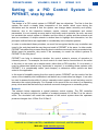
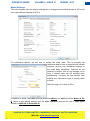
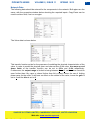
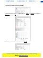
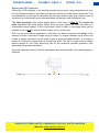
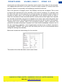
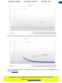
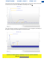
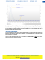
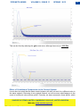
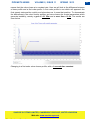
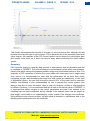
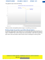
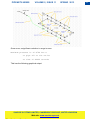
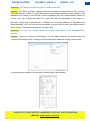
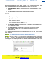
PIPENET® NEWS VOLUME 2, ISSUE 11 SPRING 2013 PIPENET ® - Leading the Way in Fluid Flow Analysis 1. News 1.1. PIPENET at OTC 2013 ............................................................................................. 2 1.2. PIPENET at FireExpo 2013 ...................................................................................... 2 2. Setting up a PID Control System in PIPENET® Step by Step 2.1. Introduction ............................................................................................................ 3 2.2. Network ..................................................................................................................... 3 2.3. Model Settings .......................................................................................................... 4 2.4. Network Data ............................................................................................................ 5 2.5. Setting the PID Controller ......................................................................................... 7 2.6. Optimising the Controller ......................................................................................... 10 2.7. The Effect of Transient Events ................................................................................ 13 2.8. The Effect of the Network ........................................................................................ 14 2.9. The Effect of Components ...................................................................................... 15 3. How to Reduce Pressure Surge in a Dry Deluge System 3.1. Introduction ............................................................................................................. 18 3.2. Setting up the Model ............................................................................................... 18 3.3. Building a simple Accumulator ................................................................................ 20 3.4. Using Smaller Pipes ................................................................................................ 22 3.5. Conclusions ............................................................................................................. 24 4. Frequently Asked Questions 5. Contact Us SUNRISE SYSTEMS LIMITED, CAMBRIDGE CB25 9QZ, UNITED KINGDOM Web site: www.sunrise-sys.com 1 PIPENET® NEWS VOLUME 2, ISSUE 11 SPRING 2013 News PIPENET at OTC 2013 PIPENET will be at the Offshore Technology Conference in Houston, Texas from the 6 th to the 9th May 2013 in booth 11504. The offshore technology conference is the world’s leading event in the fields of drilling, exploration, production and environmental protection in the development of offshore resources. We hope to see you all there....... PIPENET at FireExpo 2013 ..........except if you are attending FireExpo 2013!!! PIPENET will also be at the Fifteenth International Fire Protection Equipment Technology Conference and Exposition, from the 7th to the 9th May at the China National Convention Center in Beijing. We will be there with our Dealer Woshan Technology (Beijing) Co. Ltd. FireExpo is the largest international fire protection event for the exchange and exhibition of fire protection equipment. SUNRISE SYSTEMS LIMITED, CAMBRIDGE CB25 9QZ, UNITED KINGDOM Web site: www.sunrise-sys.com 2 PIPENET® NEWS VOLUME 2, ISSUE 11 SPRING 2013 Setting up a PID Control System in PIPENET, step by step Introduction The design of a PID control system in PIPENET has two objectives. The first is that the system can reach a steady state irrespective of the events which occur during the simulation and the second is that the system can change states smoothly and quickly. However, due to the interaction between events, network components and control parameters, it is not normally an easy task to build such control systems. As such, we must not consider the control system in isolation and the effect of events and the network must also be considered. A simple network is studied here to highlight their interaction, but the principles outlined below are applicable to considerably more complex systems. In order to understand these principles, we must first recognise that the way controllers are tuned in the real plant and the way they are tuned in PIPENET is the same. In other words, PIPENET simulates this process whereby plant controllers are tuned during commissioning. Which begs the question; why would it be necessary to model the control systems in PIPENET in the first place? PIPENET can help to determine whether the control system’s manner of operation is inherently sound. For example, the level control of a tank can be found either on the outlet or the inlet, or can even use a simple switch, rather than a PID controller. If it is a switch, it must be determined whether any hysteresis is required. In modelling these systems with PIPENET, it is considerably easier (and cheaper) to determine which options are best suited to the application. In the event of instability arising from the control system, PIPENET can be used to find the cause of the instability and troubleshoot well before any construction has begun. It can also be used to assess the benefits of using a cascade control system as well as being used to determine the control philosophy. For example in the event of the run-down of an operating pump, what would be the best way to achieve a smooth changeover to a standby pump. Network The network below represents a typical pressure control system. The PID controller regulates the valve’s position to maintain a constant pressure of 9.0 Bar G at the valve’s outlet. The simulation will model the response of the control system when the upstream pressure changes from 15 Bar G to 20 Bar G. SUNRISE SYSTEMS LIMITED, CAMBRIDGE CB25 9QZ, UNITED KINGDOM Web site: www.sunrise-sys.com 3 PIPENET® NEWS VOLUME 2, ISSUE 11 SPRING 2013 Model Settings The only changes from the default settings are to change the simulation length to 100 s and set a user defined timestep of 0.02 s. For calculation options, we will look at setting the initial state. This is normally not recommended for use in networks with control systems, as they can sometimes diverge in the initial state calculation. However as the network is simple, with a long enough run-in time, a steady state can be reached quite satisfactorily, meaning we can benefit from starting the calculation from a steady state solution. Note the long run in time of 200s. In addition to these, the units selected should be Metric, the fluid should be Water at 20o C (which is the default setting) and the pipe schedule selected for use in pipe types should be ANSI 36.10 Schedule 40. SUNRISE SYSTEMS LIMITED, CAMBRIDGE CB25 9QZ, UNITED KINGDOM Web site: www.sunrise-sys.com 4 PIPENET® NEWS VOLUME 2, ISSUE 11 SPRING 2013 Network Data The following data should be entered for the components in the network. Both pipes are the same, with the properties window below denoting the required inputs. Copy-Paste can be used to achieve this, if set on one pipe. The Valve data is shown below This transfer function exists for the purposes of modelling the physical characteristics of the valve. In order to model the physical open and closure time of the valve, the ramp up and down limits of the transfer function can be set to 0.2/s and -0.2/s respectively. Furthermore, the output range is limited to being between 0 and 1, as the valve cannot be open further than fully open or closed further than fully closed, hence the use of limiting power ramp for the order. It will have no effect on the control of the valve, hence the gain is set to 1 and the bias is set to 0. SUNRISE SYSTEMS LIMITED, CAMBRIDGE CB25 9QZ, UNITED KINGDOM Web site: www.sunrise-sys.com 5 PIPENET® NEWS VOLUME 2, ISSUE 11 SPRING 2013 The pressure sensor should be set to analogue. The inlet specification should be a power ramp from 15 Bar G to 20 Bar G set to happen in 5 seconds starting at the 5 s mark. The outlet specification should be a constant at 5 Bar G. SUNRISE SYSTEMS LIMITED, CAMBRIDGE CB25 9QZ, UNITED KINGDOM Web site: www.sunrise-sys.com 6 PIPENET® NEWS VOLUME 2, ISSUE 11 SPRING 2013 Setting the PID Controller Setting up a PID controller is an iterative process and as such, many parameters can only be truly determined after a succession of test runs and may not be known at the start. The key parameters in this type of calculation are the gain and the reset time. Others, such as set points, are often known at the start and these can be input with confidence here. The input set point is the control target, which in this case is 9 Bar G. The output set point represents the initial output signal, were the input signal the input set point in a proportional control system. If this is not known, which is likely, a mid-range value can be selected, such as 0.5 for an information output, as it is in this case. Gain is a far more difficult parameter to nail down, as without extensive knowledge of the network its value could take a large range of values. In simple networks, such as the one shown, a simple technique can be used to gain a good first approximation. It is simply a matter of running the network with no control loop at all. The aim is to see how the system would respond to the valve slamming shut at the maximum possible pressure, thus generating the greatest oscillation. Using the following network, with the associated valve closure profile, the following graph is obtained: SUNRISE SYSTEMS LIMITED, CAMBRIDGE CB25 9QZ, UNITED KINGDOM Web site: www.sunrise-sys.com 7 PIPENET® NEWS VOLUME 2, ISSUE 11 SPRING 2013 The graphical results show that the maximum oscillation caused by this scenario is approximately 18.4 Bar G. This means that the initial gain should be set to counter this at Bar Bar While this is a simple procedure for such a basic network, in larger networks it can quite clearly be seen that this could become impractical. In these situations the first approximation for the gain should be left to engineering experience. In case of doubt, it is always best to start with a small gain and then increase it step by step until the model delivers satisfactory results, reaching steady operation quickly and smoothly. At this point, it must be determined which type of controller needs to be used. This is usually known to the control system engineer, but as a rule of thumb, PID controllers are the most effective, but the most expensive, proportional controllers (P controllers) are the cheapest and least effective and PI controllers normally offer a balance between the two. For more information on the model equations of the different types of controllers, please refer to the footnote at the bottom of this article, or the PIPENET User Manual, found in the help menu. For this network a PI controller will be used as it is the most commonly chosen type and as such, the parameters that will be focused on are those that require tuning in a PI controller. Before that, however, a brief word on differential control. By introducing a differential term, oscillations can be dampened faster resulting in greater stability. These require the extra term known as the rate time, which determines the effect of the differential term. If set too large (> Reset Time/4), instabilities can occur as the differential control term takes over. Returning to our Proportional – Integral controller, due to the integral term, the reset time must be set. The reset time should be tuned based on the dynamic response of the network. In the given example, the pressure change occurs in a space of 5 s and any pressure waves present can travel throughout the entire network in fractions of a second, SUNRISE SYSTEMS LIMITED, CAMBRIDGE CB25 9QZ, UNITED KINGDOM Web site: www.sunrise-sys.com 8 PIPENET® NEWS VOLUME 2, ISSUE 11 SPRING 2013 meaning that an initial guess for the reset time can be made of the order of a few seconds. If an appropriate reset time is not found, it is best to simply consider a 5 second reset time and then reduce it incrementally until satisfactory results are achieved. Due to the presence of integral control, Anti-Windup must also be considered. This is used to improve the response time of the controller, in the event of overshoot. For example, were the valve fully open, but the pressure not yet high enough, the controller would continue to increase its output value, even though the physicality of the situation would not allow it. Were the inlet pressure then increased and the control pressure then higher than required, the controller would take a long time to respond as its output value would be greater than the one it should be at. Anti-Windup prevents this and as such will be used in this scenario. Tracking time is the constant used in the anti-windup equation, used to determine how quickly the controller will prevent overshoot, but it also must be calibrated. However, due to the care required in calibration, most integral-based controllers have a default value that is unchangeable. PIPENET also comes with this facility and its use is recommended above setting the tracking time manually. Below can be seen the initial settings for the controller. The results of the initial calculation can be seen below. SUNRISE SYSTEMS LIMITED, CAMBRIDGE CB25 9QZ, UNITED KINGDOM Web site: www.sunrise-sys.com 9 PIPENET® NEWS VOLUME 2, ISSUE 11 SPRING 2013 While stability is good and oscillations minimal, it can be seen that it takes around 100s before stabilising at 9 Bar G. It also has a fairly high peak at 10.7 Bar G, which could be considered unacceptable. This leads onto the next part. Optimising the Controller We must now consider the effect of varying the gain. As we wish to increase the rate at which the solution stabilises at our desired value, the gain must be increased. The three graphs below show the results when the gain is increased to -0.1 Bar G by increments of 0.025 Bar. SUNRISE SYSTEMS LIMITED, CAMBRIDGE CB25 9QZ, UNITED KINGDOM Web site: www.sunrise-sys.com 10 PIPENET® NEWS VOLUME 2, ISSUE 11 SPRING 2013 As an increase in gain has been successful, a further increase in gain can be considered. The gain having further been increased, instability can be seen. As such, the gain shall be kept at -0.075 /Bar. SUNRISE SYSTEMS LIMITED, CAMBRIDGE CB25 9QZ, UNITED KINGDOM Web site: www.sunrise-sys.com 11 PIPENET® NEWS VOLUME 2, ISSUE 11 SPRING 2013 The reset time will now be optimised in a similar manner. As we know it can be of the order of seconds, we can reduce the reset time to something lower, say 1s. This initial reduction has shown a marked improvement in the convergence and stability of the system. Looking now at what happens if we reduce further. SUNRISE SYSTEMS LIMITED, CAMBRIDGE CB25 9QZ, UNITED KINGDOM Web site: www.sunrise-sys.com 12 PIPENET® NEWS VOLUME 2, ISSUE 11 SPRING 2013 By reducing the reset time further, we have once more introduced instability into our network, which is undesirable, despite the improvement in pressure peak reduction and convergence. For a real case, this process would be iterated several more times, to find the optimal solution, as well as looking for suitable buffers in case of unforeseen circumstances as will be covered in the next part. For now, it has been determined that the optimal parameters for our controller are a Gain of -0.075 /Bar and a Reset Time of 1s. The Effect of Transient Events So far, we have only looked at a single transient event, that being a 5s increase in the pressure from 15 Bar G to 20 Bar G, which could be associated with the switching on of a pump or some other normal operating procedure. Assuming now that something different occurred, such as a 10 Bar G pressure increase due to the system cutting off the supply to other consumers, while maintaining the pump speed, meaning that rather than increasing the pressure from 15 Bar G to 20 Bar G, it now went to 25 Bar G. Would the network still be stable? Below can be seen the results from the same network, but with the higher pressure changing to 25 Bar G in the same amount of time. This has clearly shown that in this case, our control system is not suitable, causing considerable instability. Looking at our previous results, we need to see what we can do to mitigate this instability. The dominant term is the Gain, so this is what we should first attempt to change, as it affects both the proportional and integral terms (as well as any differential term we may have had). As such, it has been reduced to -0.025 /Bar. SUNRISE SYSTEMS LIMITED, CAMBRIDGE CB25 9QZ, UNITED KINGDOM Web site: www.sunrise-sys.com 13 PIPENET® NEWS VOLUME 2, ISSUE 11 SPRING 2013 As can be seen, the instability has been removed by the decrease in gain. For this, we have lost a little of the convergence speed and our pressure peak has increased. It would be up to the engineer to decide whether this was acceptable or not and whether the sort of pressure increase seen here was likely. The Effect of the Network It is very important to note that one control system does not fit all and that they need to be tailored to the network in which they are installed. To demonstrate this, we will make a few small changes to the network. Firstly, we will demonstrate the effect of increasing the pipe length to 300m (from 200m), using our previously optimised network. SUNRISE SYSTEMS LIMITED, CAMBRIDGE CB25 9QZ, UNITED KINGDOM Web site: www.sunrise-sys.com 14 PIPENET® NEWS VOLUME 2, ISSUE 11 SPRING 2013 This can be fixed by reducing the gain once more, although here only to -0.05 /Bar. Effect of Constituent Components in the Control System It must also be noted that the same control system will also not work for a different valve in the same network. Returning to our original network, we will now see what happens in the event of a different valve closure profile. Currently, we have assumed a linear profile, which SUNRISE SYSTEMS LIMITED, CAMBRIDGE CB25 9QZ, UNITED KINGDOM Web site: www.sunrise-sys.com 15 PIPENET® NEWS VOLUME 2, ISSUE 11 SPRING 2013 means that the valve closes at a constant rate. Here we will look at the difference between a linear profile and a first order profile. A first order profile is one which will approach the final steady state position quickly and slow down as it nears that position. To demonstrate the differences in the valve closure profiles, we have chosen the control parameters which generate instability, namely a gain of -0.1 /Bar and a reset time of 0.2s. The results are seen below. Changing to a first order valve closure profile, with a 1 second time constant: SUNRISE SYSTEMS LIMITED, CAMBRIDGE CB25 9QZ, UNITED KINGDOM Web site: www.sunrise-sys.com 16 PIPENET® NEWS VOLUME 2, ISSUE 11 SPRING 2013 This clearly demonstrates the benefit of this type of valve closure profile, although this will be determined by the type of valve chosen. This is because due to the smoother manner of valve closure, the response of the PID Control system can be faster (by using higher gain and smaller reset time), as it does not have to worry about controlling the valve closure speed. Summary PID Controller tuning is a step by step process of improvement and re-calculation and this is modelled in PIPENET. They should always be tuned based on the worst case scenario, namely that which causes the greatest pressure surge over the shortest period of time. The response of PID controllers is slower but more stable with lower gain and a larger reset time, hence it is recommended to start with the parameters set as such then slowly increasing the gain and decreasing the reset time until results are satisfactory. In the case of differential control, the rate time should be around 25% of the reset time to maximise stability. Anti-Windup is also recommended for use to prevent the control system from taking a long time to reset the output value in case of overshoot. As this is often specified by default in industry, it is recommended that this is kept to the default value in PIPENET. It is important that safety margins in the control parameters are kept if the network to be modelled has not been completed, as any change in the network (even one as simple as pipe length) could result in an unsatisfactory control system if the margins are insufficient. Using different valve closure profiles, will also allow a reduction in oscillations, due to the damping effect being external to the controller. SUNRISE SYSTEMS LIMITED, CAMBRIDGE CB25 9QZ, UNITED KINGDOM Web site: www.sunrise-sys.com 17 PIPENET® NEWS VOLUME 2, ISSUE 11 SPRING 2013 How to Reduce Pressure Surge in a Dry Deluge System Introduction Pressure surge is a commonly found phenomenon when a dry deluge system is primed. In the worst cases, the maximum pressure can reach values of well over 100 Bar G when the most remote nozzle is primed. This occurs as the resistance to flow is increasing at which point an instant change of fluid from air to water occurs, decreasing the flowrate instantly as well. The following network is one which suffers from such a problem, the maximum pressure peak reaching 122.05 Bar G. Here we will analyse two cost-efficient ways to minimise the pressure surge. The first is to create a simple accumulator, using a short dry pipe near the most remote nozzles and the second is to reduce the pipe sizes, limiting the flowrate as the network primes. Setting up the model The network data is as follows: Inlet Pressure: 8 Bar G (constant throughout the simulation) Deluge Valve Open Time: 5 s Main Pipe Nominal Diameter: 100 mm Riser Nominal Diameter: 80 mm SUNRISE SYSTEMS LIMITED, CAMBRIDGE CB25 9QZ, UNITED KINGDOM Web site: www.sunrise-sys.com 18 PIPENET® NEWS VOLUME 2, ISSUE 11 SPRING 2013 Branch Nominal Diameter: 50 mm The pipe at the far end of the middle deluge ring should act as an accumulator when the far nozzles are primed. PIPENET’s dry pipe model assumes all the air is evacuated as priming occurs, which means that when the pipe at the far end is filled, it will result in an extra surge, rather than acting in a damping manner as it should. As such, it is best to model this as two accumulators as follows. These “pseudo-accumulators” will have the same dimensions as the pipe that they have replaced. This allows us to calculate a more accurate maximum pressure. In this case, it turns out that the most remote nozzles are in fact those at the top and bottom branches of the deluge system (looking at the pressure extrema summary data in the output). Maximum pressure is 122.052 bar G on pipe 163 at the outlet at time 10.88200 seconds SUNRISE SYSTEMS LIMITED, CAMBRIDGE CB25 9QZ, UNITED KINGDOM Web site: www.sunrise-sys.com 19 PIPENET® NEWS VOLUME 2, ISSUE 11 SPRING 2013 The graphical output shows the following. These are clearly unacceptable pressure surges, so something must be done. Building a Simple Accumulator near the Most Remote Nozzles A cheap and simple solution to this problem is to extend the length of the branches by 1m beyond the end nozzles, using these to act as accumulators, cushioning the pressure surge. In PIPENET these will be modelled as real accumulators, rather than using the dry pipe model, as the accumulator model is better suited to modelling the cushioning effect. SUNRISE SYSTEMS LIMITED, CAMBRIDGE CB25 9QZ, UNITED KINGDOM Web site: www.sunrise-sys.com 20 PIPENET® NEWS VOLUME 2, ISSUE 11 SPRING 2013 The accumulator input data is shown below. Both should be the same. The results speak for themselves: Maximum pressure is 18.3877 bar G on pipe 163 at the outlet at time 11.03400 seconds The pressure surge peak has been reduced by a factor of nearly 7 and is now considerably more manageable. The graphical result is shown below. SUNRISE SYSTEMS LIMITED, CAMBRIDGE CB25 9QZ, UNITED KINGDOM Web site: www.sunrise-sys.com 21 PIPENET® NEWS VOLUME 2, ISSUE 11 SPRING 2013 Using Smaller Pipes to reduce the flow rate when primed Here, the pipes in the network have been made smaller in order to reduce the flow rate and hence, reduce the surge, by increasing the pressure loss. However, it must be noted that the flow velocity in the pipes and the pressure at the inlet to the nozzle must be checked carefully as they still need to satisfy the original deluge system requirements. The changes to the pipe sizes are as follows. Main Pipe Nominal Diameter: 65 mm Riser Nominal Diameter: 50 mm Branch Nominal Diameter: 32 mm Remote Nominal Diameter: 25 mm SUNRISE SYSTEMS LIMITED, CAMBRIDGE CB25 9QZ, UNITED KINGDOM Web site: www.sunrise-sys.com 22 PIPENET® NEWS VOLUME 2, ISSUE 11 SPRING 2013 Once more, a significant reduction in surge is seen. Maximum pressure is 16.9769 bar G on pipe 163 at the outlet at time 10.84400 seconds This has the following graphical output. SUNRISE SYSTEMS LIMITED, CAMBRIDGE CB25 9QZ, UNITED KINGDOM Web site: www.sunrise-sys.com 23 PIPENET® NEWS VOLUME 2, ISSUE 11 SPRING 2013 After priming, the lowest nozzle pressure on the most remote nozzle (21), is now approximately 1.95 Bar G, with a minimum flow velocity of around 3.9 m/s. The maximum flow velocity is 6.5 m/s. These would have to be checked against the requirements of the deluge system as well as ensuring that noise and vibration in the pipes was not too great, and may require further optimisation of pipe sizes to achieve the desired result. Conclusions We have seen here two cost-effective and simple ways of considerably reducing the maximum pressure in a pressure surge scenario caused by deluge system priming, reducing surge by a factor of almost 7 in both cases. SUNRISE SYSTEMS LIMITED, CAMBRIDGE CB25 9QZ, UNITED KINGDOM Web site: www.sunrise-sys.com 24 PIPENET® NEWS VOLUME 2, ISSUE 11 SPRING 2013 Frequently Asked Questions Question: Which friction factor does PIPENET use in its calculation for pressure loss due to friction? Answer: The friction factor used by PIPENET is the Fanning friction factor ( ), but it is sometimes confused with the Moody friction factor ( ). They are related by the following: Using this notation the friction can be written as below: Question: How do I import a graphical underlay? Answer: Open a new file in PIPENET and under View, click on the Import graphical underlay option: A dialog will open allowing the user to choose the file he wishes to import as an underlay. Not the underlay format must be one of the following: .dxf, .emf and .wmf. Question: Is it possible for me to enter a higher velocity for smaller diameter pipe in the pipe types maximum velocity section? I currently generate the following warning when I try to do so: SUNRISE SYSTEMS LIMITED, CAMBRIDGE CB25 9QZ, UNITED KINGDOM Web site: www.sunrise-sys.com 25 PIPENET® NEWS VOLUME 2, ISSUE 11 SPRING 2013 Answer: It is not possible to have a higher flow velocity for smaller pipes. This is to allow the pipe-sizing to work by always selecting the smallest pipe allowable for the required flow rate. If you have already sized all your pipes, you can split the schedule into two, one with larger diameters and one with smaller diameters, both of which can have different maximum velocities. Both schedules can be set up with the same physical parameters in the Schedule library. These can then be entered into the network and will generate warnings if these velocities are exceeded. Question: Which orifice plate model should I choose? Answer: This depends on the criteria of your design. Generally speaking, however, the “BS-1042” model is normally for the measurement purposes, Heriot-Watt is normally for scientific research purposes and the Crane model is normally more popular for the engineering projects. A more detailed explanation is given below of each orifice plate model: Plates with flange tappings in accordance with BS1042, taking into account pressure recovery downstream. The restrictions of BS1042 are applied, so plates may only be used in pipes with diameters in the range 2 – 14 inches (50.8 – 355.6 mm). Furthermore, the ratio of the orifice diameter to the pipe diameter must be in the range 0.1 – 0.748 for pipes over 4 inches in diameter. Question: How do I change the number of decimal places displayed? Answer: Using the same form, select the measure/unit in the left hand pane, and choose the number of decimal places using the “precision” drop down. Note this works even if you are using one of the standard unit systems like SI or Metric. Don’t worry that the measure and unit are greyed out, you can still select them and change the number of decimal places to be shown. You can separately choose the number of decimal places displayed for general text use (dialogs etc), and the number displayed when annotating or labelling the Schematic drawing. You will generally want fewer on the schematic drawing, to avoid “clutter”. Question: Does changing the precision affect the accuracy of the calculations? Answer: No. It only affects the number of decimal places when the results are displayed. Question: Are my unit selections saved when I exit PIPENET? Answer: The .sdf file contains information about the desired units and precision. So if you save the file when you exit, you will automatically be saving your unit selections in the file and the next time you (or someone else) opens the file they will have the same unit selections. SUNRISE SYSTEMS LIMITED, CAMBRIDGE CB25 9QZ, UNITED KINGDOM Web site: www.sunrise-sys.com 26 PIPENET® NEWS VOLUME 2, ISSUE 11 SPRING 2013 Question: Do I have to do this every time I create a new file? Answer: No. When you have chosen a set of units and precisions that you like, click the “Save as defaults” button. This will save them as a personal preference in the registry, and whenever you create a new sdf file it will be initialised with your saved default values (of course, you can change the values for your new sdf file afterwards if you want to). Do note though that Transient has a different set of saved defaults to Standard and Spray/Sprinkler. So if you use all three modules, you will need to save your default values twice (once for Transient and once for the other two). Question: Is there any existing library for nozzles and valves in the Spray/Sprinkler module? Answer: There is no pre-set nozzle library. You can add nozzles to the system either by clicking on the library menu, clicking on the nozzle option and then storing a new nozzle: or by entering the details in the property window under User-defined: SUNRISE SYSTEMS LIMITED, CAMBRIDGE CB25 9QZ, UNITED KINGDOM Web site: www.sunrise-sys.com 27 PIPENET® NEWS VOLUME 2, ISSUE 11 SPRING 2013 Below is a brief description of the valves available in the Spray/Sprinkler module. Note, these are available as separate components and some require extra user-input: An overboard dump valve (or pressure safety valve) which operates with a trigger pressure. The deluge valve which follows the following modelling equation: where: P is the pressure drop, Q is the flow rate K is a constant for the valve x is a constant for the valve (usually 1 or 2) The non-return valve allows unrestricted flow in the positive direction and prevents flow in the reverse direction The elastomeric valve allows the user to achieve the required input pressure, output pressure, pressure drop or flow rate without the need to input valve characteristic data. For a detailed description of these valves, please look through the help menu Contents under Modelling. Question: Can I add user-defined fittings in the Spray/Sprinkler module? Answer: The range of fittings in the Spray/Sprinkler module is based on the guidelines of the NFPA. If you wish to add some device or fitting not included in the range of available fittings then you may be able to consider the use of an equipment item which allows you to input a defined equivalent length: SUNRISE SYSTEMS LIMITED, CAMBRIDGE CB25 9QZ, UNITED KINGDOM Web site: www.sunrise-sys.com 28 PIPENET® NEWS VOLUME 2, ISSUE 11 SPRING 2013 CONTACT US Technical Support [email protected] Sales [email protected] SUNRISE SYSTEMS LIMITED, CAMBRIDGE CB25 9QZ, UNITED KINGDOM Web site: www.sunrise-sys.com 29