1
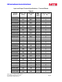
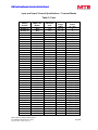
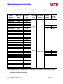
MTE SERIES RLW World REACTORS USER INSTALLATION MANUAL Form: RLW-UIM-E REL: February 2013 REV. 005 © 2013 MTE Corporation RLW Line/Load Reactor User Installation Manual IMPORTANT USER INFORMATION NOTICE MTE Series RLW reactors are components designed to improve the reliability of three or single phase AC adjustable frequency drives, DC drives and a wide variety of other types of power electronic equipment. In addition they provide input line current harmonic mitigation and 100 foot long lead protection for inverter fed motors. MTE reactors are available in a large number of current ratings and a variety of inductance values. The suitability of a reactor for a specific application must therefore be ultimately determined by the customer. In no event will MTE Corporation assume responsibility or liability for any direct or consequential damages resulting from the use or application of reactors. Nor will MTE Corporation assume patent liability with respect to the use of information, circuits or equipment described in this instruction manual. Data subject to change without notice. Form RLW-UIM-E February 2013 Supersedes RLW-UIM-E May 2012 Page 2 RLW Line/Load Reactor User Installation Manual Table of Contents IMPORTANT SAFETY INFORMATION WARNING ........................................................... 4 INTRODUCTION......................................................................................................................... 6 UPON RECEIPT OF A REACTOR:..................................................................................................... 6 REPAIR/EXCHANGE PROCEDURE .................................................................................................. 6 REACTOR INSTALLATION ...................................................................................................... 7 POWER WIRING CONNECTION ...................................................................................................... 8 INPUT AND OUTPUT TERMINAL SPECIFICATIONS – TERMINAL BLOCKS ........................................ 9 Table 2...................................................................................................................................... 9 INPUT AND OUTPUT TERMINAL SPECIFICATIONS – LUG KITS ..................................................... 11 Table 3.................................................................................................................................... 11 GROUNDING ............................................................................................................................... 12 CONNECTION DIAGRAMS.................................................................................................... 13 SINGLE PHASE CONNECTION ....................................................................................................... 13 STARTUP.................................................................................................................................... 14 SAFETY PRECAUTIONS ................................................................................................................ 14 SEQUENCE OF OPERATION .......................................................................................................... 14 MODEL CODE PART NUMBER CONFIGURATION ........................................................ 16 MECHANICAL DATA .............................................................................................................. 17 OPEN PANEL ............................................................................................................................... 17 ENCLOSED REACTOR .................................................................................................................. 20 FACTORY CONFIGURED OPTIONS ................................................................................... 23 KIT-0038 ................................................................................................................................... 23 KIT-0039 ................................................................................................................................... 23 KIT-0040 ................................................................................................................................... 23 OUTLINE DRAWINGS............................................................................................................. 24 FIGURE 1 SNAP BASE MOUNT FIGURE 2 35MM DIN MOUNT OPTION ............................ 24 FIGURE 3 STANDARD MOUNTING ............................................................................................... 24 FIGURE 4 CAB – 8 ....................................................................................................................... 25 FIGURE 5 CAB 13V ..................................................................................................................... 25 FIGURE 6 CAB 17V .................................................................................................................... 26 FIGURE 7 CAB 17C .................................................................................................................... 26 FIGURE 8 CAB 26C .................................................................................................................... 27 SPECIFICATION DATA .......................................................................................................... 28 ALTITUDE DERATING AND INDUCTANCE CURVE CHARTS .................................... 29 Data subject to change without notice. Form RLW-UIM-E February 2013 Supersedes RLW-UIM-E May 2012 Page 3 RLW Line/Load Reactor User Installation Manual IMPORTANT SAFETY INFORMATION WARNING ONLY A QUALIFIED ELECTRICIAN CAN CARRY OUT THE ELECTRICAL INSTALLATION OF LINE/LOAD REACTORS WARNING High voltage is used in the operation of line/load reactors. Use Extreme caution to avoid contact with high voltage when operating, installing or repairing equipment containing line/load reactors. INJURY OR DEATH MAY RESULT IF SAFETY PRECAUTIONS ARE NOT OBSERVED. Line/load reactors are used in conjunction with inverters, or other electrical equipment that may feedback lethal voltages. Follow the safety instructions in the equipment used with the reactor in addition to the safety instruction in this manual. WARNING The opening of the branch circuit protective device may be an indication that a fault current has been interrupted. To reduce the risk of fire or electrical shock, line/load reactors should be examined and replaced if damaged. Data subject to change without notice. Form RLW-UIM-E February 2013 Supersedes RLW-UIM-E May 2012 Page 4 RLW Line/Load Reactor User Installation Manual IMPORTANT SAFETY INFORMATION WARNING, CONT. WARNING An upstream disconnect/protection device must be used as required by the National Electrical Code (NEC). WARNING Even if the upstream disconnect/protection device is open, a drive or inverter downstream of the line/load reactor may feedback high voltage to the reactor. The inverter or drive safety instructions must be followed. INJURY OR DEATH MAY RESULT IF THE DRIVE SAFETY PRECAUTIONS ARE NOT OBSERVED. WARNING The frame of line/load reactors must be grounded at least at one of the reactor’s mounting holes. WARNING Only spare parts obtained from MTE Corporation or an authorized MTE distributor can be used Data subject to change without notice. Form RLW-UIM-E February 2013 Supersedes RLW-UIM-E May 2012 Page 5 RLW Line/Load Reactor User Installation Manual INTRODUCTION This manual was specifically developed to assist in the installation, interconnection and operation of MTE Corporation Series RLW reactors This manual is intended for use by personnel experienced in the operation and maintenance of electronic drives, inverters and similar types of power electronic equipment. Because of the high voltages required by the equipment connected to line/load reactors and the potential dangers presented by rotating machinery, it is essential that all personnel involved in the operation and maintenance of line/load reactors know and practice the necessary safety precautions for this type of equipment. Personnel should read and understand the instructions contained in this manual before installing, operating or servicing line/load reactors and the drive to which the reactor is connected. Upon Receipt of a Reactor: MTE Line/load Reactors have been subjected to demanding factory tests before shipment. Carefully inspect the shipping container for damage that may have occurred in transit. Then unpack the filter and carefully inspect for any signs of damage. Save the shipping container for future transport of the reactor. In the event of damage, please contact and file a claim with the freight carrier involved immediately. If the equipment is not going to be put into service upon receipt, cover and store the reactor in a clean, dry location. After storage, ensure that the equipment is dry and that no condensation has accumulated on the reactor before applying power. Repair/Exchange Procedure MTE Corporation requires a Returned Material Authorization Number before it can accept any reactors that qualify for return or repair. If problems or questions arise during installation, setup, or operation of the filter, please call us for assistance at: Phone: 1-262-253-8200 FAX: 1-262-253-8222 Data subject to change without notice. Form RLW-UIM-E February 2013 Supersedes RLW-UIM-E May 2012 Page 6 RLW Line/Load Reactor User Installation Manual Reactor Installation MTE world reactors are available in open construction and in NEMA 1 and NEMA 3R enclosures. Open reactors are designed for mounting within an appropriate electrical equipment enclosure. Reactors rated 300 amperes RMS and under are designed for mounting in both a vertical and horizontal position. Larger reactors must be mounted in a horizontal position typically on the floor of the enclosure. Include the power dissipation of the reactor along with all the other components located in the enclosure to determine the internal temperature rise and cooling requirements of the enclosure. Reactors may be located in any region of the enclosure where the ambient temperature does not exceed 45 degrees C. Allow a minimum side clearances of four (4) inches and vertical clearances of six (6) inches for proper heat dissipation and access. Do not locate the reactor next to resistors or any other component with operating surface temperatures above 125 degree C. Select a well-ventilated, dust-free area away from direct sunlight, rain or moisture. Do not install in or near a corrosive environment. Avoid locations where the reactor will be subjected to excessive vibrations. NEMA 1 and NEMA 3R Enclosed world Reactor Installation MTE RLW reactors mounted in enclosures with part number, CAB-8, are designed for wall mounting. All other enclosures are designed for floor mounting and only RLW reactors 200 Amps and higher are available in a NEMA 3R enclosure. WARNING MTE NEMA 1 and NEMA 3R enclosures designed for floor mounting must be mounted with the enclosure base horizontal for proper ventilation. Wall mounting a floor mounted enclosure with the base against the wall will cause the reactor to overheat resulting in equipment damage. Allow a minimum side, front, and back clearances of twelve (12) inches and vertical clearances of eighteen (18) inches for proper heat dissipation and access. Do not locate the enclosure next to resistors or any other component with operating surface temperatures above 125 degree C. Select a well-ventilated, dust-free area away from direct sunlight, rain or moisture where the ambient temperature does not exceed 40 degrees C. Do not install in or near a corrosive environment. Avoid locations where the reactor will be subjected to excessive vibrations. Where desirable, reactors or enclosures may be mounted on vibration isolating pads to reduce audible noise. Standard vibration control pads made from neoprene or natural rubber and selected for the weight of the enclosed reactor are effective. Data subject to change without notice. Form RLW-UIM-E February 2013 Supersedes RLW-UIM-E May 2012 Page 7 RLW Line/Load Reactor User Installation Manual Power Wiring Connection WARNING Input and output power wiring to the reactor should be performed by authorized personnel in accordance with the NEC and all local electrical codes and regulations. Verify that the power source to which the reactor is to be connected is in agreement with the nameplate data on the reactor. A fused disconnect switch or circuit breaker should be installed between the reactor and its source of power in accordance with the requirements of the NEC and all local electrical codes and regulations. Refer to the drive, inverter, or other electrical equipment user manual for selection of the correct fuse rating and class. The reactor is suitable for use on a circuit capable of delivering not more than 65,000 rms symmetrical amperes at 480 volts when protected by Bussmann type JJS, KTK, KTK-R, SPP or T class fuses. Reactors are designed for use with copper conductors with a minimum temperature rating of 75 degrees C. Table 2 lists the wire range and terminal block torque requirements for the power input and output connections by reactor part number. Table 3 lists the optional lug kits and lug torque requirements for reactors with copper tab terminals by reactor part number. Refer to Figure 7 for typical electrical diagrams describing the application of reactors in both line and load applications. For reactors supplied as a component part of a drive system or a component part of power electronic apparatus follow the interconnection diagram supplied by the System Engineer. Where desirable, a flexible conduit connection to the reactor enclosure should be made to reduce audible noise. WARNING Failure to connect reactors supplied as a component part of a drive system or other power electronic system according to the system interconnection diagram supplied by the System Engineer will result in equipment damage, injury, or death. WARNING If a line reactor or a line reactor and a load reactor are used with a drive equipped with a bypass circuit, the reactors must be removed from the motor circuit in the bypass mode. Damage to the motor and other equipment will result if this warning is not observed. Data subject to change without notice. Form RLW-UIM-E February 2013 Supersedes RLW-UIM-E May 2012 Page 8 RLW Line/Load Reactor User Installation Manual Input and Output Terminal Specifications – Terminal Blocks Table 2 Catalog Number Watts Loss (Watts) Inductance (mH) Wire Range (AWG) Terminal Torque (in – lbs) RLW-00P501 2.3 22.0 22 – 10 5 RLW-00P503 3.6 46.0 22 – 10 5 RLW-00P505 4.8 74.0 22 – 10 5 RLW-00P506 5.4 92.0 22 – 10 5 RLW-0P7501 4.2 15.0 22 – 10 5 RLW-0P7503 6.6 31.0 22 – 10 5 RLW-0P7505 8.8 49.0 22 – 10 5 RLW-0P7506 10.1 61.0 22 – 10 5 RLW-01P101 4.8 10.0 22 – 10 5 RLW-01P103 7.8 21.0 22 – 10 5 RLW-01P105 10.1 33.0 22 – 10 5 RLW-01P106 11.9 42.0 22 – 10 5 RLW-01P601 6.9 6.9 22 – 10 5 RLW-01P603 10.9 14.0 22 – 10 5 RLW-01P605 15.0 23.0 22 – 10 5 RLW-01P606 17.7 29.0 22 – 10 5 RLW-02P101 9.0 5.3 22 – 10 5 RLW-02P103 14.3 11.0 22 – 10 5 RLW-02P105 19.6 18.0 22 – 10 5 RLW-02P106 22.3 22.0 22 – 10 5 RLW-03P401 12.3 3.2 22 – 10 5 RLW-03P403 19.6 6.8 22 – 10 5 RLW-03P405 13.8 11.0 22 – 10 5 RLW-03P406 23.0 14.0 22 – 10 5 RLW-04P801 19.2 2.3 22 – 10 5 RLW-04P803 26.5 4.8 22 – 10 5 RLW-04P805 31.5 7.7 22 – 10 5 RLW-04P806 37.5 10.0 22 – 10 5 RLW-07P601 40.1 1.5 22 – 10 5 RLW-07P603 37.2 3.0 22 – 10 5 RLW-07P605 47.8 4.8 22 – 10 5 RLW-07P606 53.8 6.0 22 – 10 5 Data subject to change without notice. Form RLW-UIM-E February 2013 Supersedes RLW-UIM-E May 2012 Page 9 RLW Line/Load Reactor User Installation Manual Input and Output Terminal Specifications – Terminal Blocks Table 2, Cont. Catalog Number Watts Loss (Watts) Inductance (mH) RLW-001101 RLW-001103 RLW-001105 RLW-001106 RLW-001401 RLW-001403 RLW-001405 RLW-001406 RLW-002101 RLW-002103 RLW-002105 RLW-002106 RLW-002801 RLW-002803 RLW-002805 RLW-002806 RLW-003501 RLW-003503 RLW-003505 RLW-003507 RLW-004601 RLW-004603 RLW-004605 RLW-004607 RLW-005501 RLW-005503 RLW-005505 RLW-005507 RLW-006501 RLW-006503 RLW-006505 RLW-006507 RLW-008301 RLW-008303 RLW-008305 RLW-008307 RLW-010401 RLW-010403 RLW-010405 RLW-010407 26.8 40.9 54.4 59.1 32.7 48.2 60.6 66 38.3 57.4 73.5 78 48.2 66.8 93.8 110.6 68.6 102.9 121.9 204 77.9 99.8 179.3 192 67.5 109.7 149.7 283 87.4 105.3 214.5 191 119.3 155.1 197.5 240 94 199.5 208.6 256 1.0 2.1 3.3 4.2 0.8 1.6 2.6 3.3 0.53 1.1 1.8 2.2 0.39 0.82 1.3 1.6 0.35 0.71 1.2 2.12 0.3 0.55 0.98 0.0016 0.27 0.48 0.75 1.33 0.19 0.38 0.64 1.1 0.17 0.29 0.51 0.91 0.12 0.23 0.375 0.67 Data subject to change without notice. Form RLW-UIM-E February 2013 Supersedes RLW-UIM-E May 2012 Wire Range (AWG) 22 – 10 22 – 10 22 – 10 22 – 10 22 – 10 22 – 10 22 – 10 22 – 10 14 – 6 14 – 6 14 – 6 14 – 6 14 – 6 14 – 6 14 – 6 14 – 6 14 – 6 14 – 6 14 – 6 14 – 6 14 – 6 14 – 6 14 – 6 14 – 6 6–0 6–0 6–0 6–0 6–0 6–0 6–0 6–0 6–0 6–0 6–0 6–0 6–0 6–0 6–0 6–0 Terminal Torque (in – lbs) 5 5 5 5 5 5 5 5 18 18 18 18 18 18 18 18 18 18 18 18 18 18 18 18 6-4(45) & 2-0(50) 6-4(45) & 2-0(50) 6-4(45) & 2-0(50) 6-4(45) & 2-0(50) 6-4(45) & 2-0(50) 6-4(45) & 2-0(50) 6-4(45) & 2-0(50) 6-4(45) & 2-0(50) 6-4(45) & 2-0(50) 6-4(45) & 2-0(50) 6-4(45) & 2-0(50) 6-4(45) & 2-0(50) 6-4(45) & 2-0(50) 6-4(45) & 2-0(50) 6-4(45) & 2-0(50) 6-4(45) & 2-0(50) Page 10 RLW Line/Load Reactor User Installation Manual Input and Output Terminal Specifications – Lug Kits* Table 3 Catalog Number Watts Loss (Watts) Inductance (mH) RLW-013001 RLW-013003 RLW-013005 RLW-013007 RLW-016001 RLW-016003 RLW-016005 RLW-016007 RLW-020001 RLW-020003 RLW-020005 RLW-020007 RLW-025001 RLW-025003 RLW-025005 RLW-025007 RLW-032201 RLW-032203 RLW-032205 RLW-032207 RLW-041401 RLW-041403 RLW-041405 RLW-041407 RLW-051501 RLW-051503 RLW-051505 RLW-051507 RLW-060001 RLW-060003 RLW-060005 RLW-060007 RLW-075001 RLW-075003 RLW-075005 RLW-075007 131.5 152.5 197.6 480 109.5 194.5 309.3 561 158.5 223.5 293 509 275.6 284.2 402 465 300 383 494 780 333 531 588 1007 314 496 695 1096 375 747 780 1190 468 838 858 1426 0.095 0.18 0.3 0.56 0.08 0.155 0.26 0.47 0.06 0.115 0.2 0.34 0.05 0.095 0.16 0.27 0.05 0.07 0.13 0.225 0.033 0.066 0.11 0.185 0.025 0.05 0.08 0.15 0.02 0.04 0.065 0.12 0.017 0.035 0.055 0.095 Terminal Type Copper Tab Copper Tab Lug Kit Part Number Lug Wire Range (AWG) Lug Torque (in - lbs) LUGKIT-003 2 1/0 - 2/0 4/0 150 180 250 LUGKIT-002 2/0 3/0 - 4/0 250 - 350 500 180 250 325 375 *Note: Optional LUGKIT-002 and LUGKIT-003 contains six (6) lugs for line and load connection. Proper wire gauge must be selected in accordance with the requirements of the NEC and all local electrical codes and regulations. Data subject to change without notice. Form RLW-UIM-E February 2013 Supersedes RLW-UIM-E May 2012 Page 11 RLW Line/Load Reactor User Installation Manual Grounding A stud is provided on enclosed reactors for grounding the enclosure. The enclosure must be grounded. Open reactors must be grounded at the designated grounding terminal or the reactor mounting holes if no designated grounding terminal is provided. WARNING The frame of line/load reactors must be grounded at the designated grounding terminal or one of the reactor mounting holes if no designated grounding terminal is provided. The enclosure of reactors supplied in enclosures must be grounded. INJURY OR DEATH MAY RESULT IF SAFETY PRECAUTIONS ARE NOT OBSERVED. Data subject to change without notice. Form RLW-UIM-E February 2013 Supersedes RLW-UIM-E May 2012 Page 12 RLW Line/Load Reactor User Installation Manual Connection Diagrams Load reactor connections Note RLW requires current de-rating for load applications see RLW-TRM for selection tables Conventional Line side reactor to VFD connections Note; Actual marking of U1 -U2, V1-V2, W1-W2 designations on reactor terminals in place of A1-A2, B1-B2, C1C2 as shown to left. Single phase connection Standard three phase reactors may be used for single phase applications. Refer to Application Note AN0102 for proper selection. Application Notes are available on our website at www.mtecorp.com. Data subject to change without notice. Form RLW-UIM-E February 2013 Supersedes RLW-UIM-E May 2012 Page 13 RLW Line/Load Reactor User Installation Manual STARTUP Safety Precautions Before startup, observe the following warnings and instructions: WARNING A Reactor is at line potential when the Reactor is connected to the utility. This voltage is extremely dangerous and may cause death or severe injury if you come in contact with it. WARNING High voltage is used in the operation of line/load reactors. Use Extreme caution to avoid contact with high voltage when operating, installing or repairing equipment containing reactors. RLW reactors are used in conjunction with inverters, or other electrical equipment that may feedback lethal voltages. Follow the safety instructions in the equipment used with the reactor in addition to the safety instruction in this manual. INJURY OR DEATH MAY RESULT IF SAFETYPRECAUTIONS ARE NOT OBSERVED. Sequence of Operation 1. Read and follow safety precautions. 2. After installation, ensure that: All Reactor ground terminals are connected to ground. Power wiring to the utility, drive and motor is in accordance with the interconnection diagrams supplied by the System Engineer. 3. Check that moisture has not condensed on the Reactor. If moisture is present, do not proceed with startup until the moisture has been removed. 4. Proceed with startup according to the instructions provided by the system supplier. Data subject to change without notice. Form RLW-UIM-E February 2013 Supersedes RLW-UIM-E May 2012 Page 14 RLW Line/Load Reactor User Installation Manual STARTUP, Cont. WARNING Reactors are a component part of an electrical system. Do not proceed with startup until the system startup instructions provided by the System Engineer are understood and followed. Injury, death and damage to equipment may result if the system startup instructions are not followed. WARNING Use extreme caution to avoid contact with line voltage when checking for power. INJURY OR DEATH MAY RESULT IF SAFETY PRECAUTIONS ARE NOT OBSERVED. Data subject to change without notice. Form RLW-UIM-E February 2013 Supersedes RLW-UIM-E May 2012 Page 15 RLW Line/Load Reactor User Installation Manual Model Code Part Number Configuration Model Number Code System: RLW- _ _ _ _ X X - Reactor “W” world . Current Rating (i.e. 00P5 is 0.5 Amps) Mechanical Configurations 0 = Base Mount 1 = NEMA 1 3 = NEMA 3R Reactor relative impedance no. 1- 6 (1) is lowest value Options: KIT-0038 = DIN Rail Mount KIT-0039 = RL conversion Plate KIT-0040 = Vibration Data subject to change without notice. Form RLW-UIM-E February 2013 Supersedes RLW-UIM-E May 2012 Page 16 RLW Line/Load Reactor User Installation Manual Mechanical Data Open Panel RMS Amps 0.5 0.75 1.1 1.6 2.1 3.4 4.8 7.6 11 14 Open Part Number Open PN Wt RLW-00P501 1.5 RLW-00P503 1.5 RLW-00P505 1.6 RLW-00P506 1.6 RLW-0P7501 1.4 RLW-0P7503 1.5 RLW-0P7505 1.5 RLW-0P7506 1.6 RLW-01P101 1.5 RLW-01P103 1.6 RLW-01P105 1.6 RLW-01P106 1.7 RLW-01P601 1.5 RLW-01P603 1.6 RLW-01P605 1.6 RLW-01P606 1.7 RLW-02P101 1.5 RLW-02P103 1.6 RLW-02P105 1.7 RLW-02P106 1.7 RLW-03P401 1.6 RLW-03P403 1.6 RLW-03P405 2.7 RLW-03P406 2.8 RLW-04P801 1.7 RLW-04P803 1.8 RLW-04P805 2.8 RLW-04P806 4 RLW-07P601 1.8 RLW-07P603 2.8 RLW-07P605 4.1 RLW-07P606 4.2 RLW-001101 2.7 RLW-001103 4.2 RLW-001105 5.3 RLW-001106 7.1 RLW-001401 2.8 RLW-001403 4.3 RLW-001405 7.1 RLW-001406 9.4 Fig 1-2 1-2 1-2 1-2 1-2 1-2 1-2 1-2 1-2 1-2 1-2 1-2 1-2 1-2 1-2 1-2 1-2 1-2 1-2 1-2 1-2 1-2 3 3 1-2 1-2 3 3 1-2 3 3 3 3 3 3 3 3 3 3 3 A width 4.5 4.5 4.5 4.5 4.5 4.5 4.5 4.5 4.5 4.5 4.5 4.5 4.5 4.5 4.5 4.5 4.5 4.5 4.5 4.5 4.5 4.5 4.4 4.4 4.5 4.5 4.4 4.4 4.5 4.4 4.4 4.4 4.4 4.4 4.4 6 4.4 4.4 6 6 B Height 3.7 3.7 3.7 3.7 3.7 3.7 3.7 3.7 3.7 3.7 3.7 3.7 3.7 3.7 3.7 3.7 3.7 3.7 3.7 3.7 3.7 3.7 5 5 3.7 3.7 5 5 3.7 5 5 5 5 5 5 5.8 5.3 5 5.8 5.8 Dimension in inches C Depth D 1.5 0.0 1.5 0.0 1.5 0.0 1.5 0.0 1.5 0.0 1.5 0.0 1.5 0.0 1.5 0.0 1.5 0.0 1.5 0.0 1.5 0.0 1.5 0.0 1.5 0.0 1.5 0.0 1.5 0.0 1.5 0.0 1.5 0.0 1.5 0.0 1.5 0.0 1.5 0.0 1.5 0.0 1.5 0.0 2.8 2.0 2.8 2.0 1.5 0.0 1.5 0.0 2.8 2.0 3.1 2.1 1.5 0.0 2.8 2.0 3.1 2.1 3.1 2.1 2.8 2.0 3.1 2.1 3.5 2.6 2.9 2.1 2.8 2.0 3.1 2.1 2.9 2.1 3.3 2.5 E 4 4 4 4 4 4 4 4 4 4 4 4 4 4 4 4 4 4 4 4 4 4 1.4 1.4 4 4 1.4 1.4 4 1.4 1.4 1.4 1.4 1.4 1.4 2 1.4 1.4 2 2 Note: DIN rail kit only available for figure 1-2 units only. Dimensional details contained here depict overall reactor sizes. See mtecorp.com for complete mechanical details and CAD drawing download. Data subject to change without notice. Form RLW-UIM-E February 2013 Supersedes RLW-UIM-E May 2012 Page 17 F - RLW Line/Load Reactor User Installation Manual Open Panel, Cont. RMS Amps 21 28 35 46 55 65 83 104 130 160 Open Part Number Open PN Wt RLW-002101 4.2 RLW-002103 7.2 RLW-002105 10 RLW-002106 13.3 RLW-002801 5.1 RLW-002803 9.5 RLW-002805 10.4 RLW-002806 14.3 RLW-003501 10 RLW-003503 13 RLW-003505 18 RLW-003507 16 RLW-004601 13 RLW-004603 17 RLW-004605 24 RLW-004607 29 RLW-005501 18 RLW-005503 20 RLW-005505 26 RLW-005507 35 RLW-006501 18 RLW-006503 22 RLW-006505 26 RLW-006507 44 RLW-008301 19 RLW-008303 26 RLW-008305 35 RLW-008307 54 RLW-010401 22 RLW-010403 28 RLW-010405 41 RLW-010407 57 RLW-013001 26 RLW-013003 37 RLW-013005 52 RLW-013007 80 RLW-016001 34 RLW-016003 49 RLW-016005 53 RLW-016007 75 Fig 3 3 3 3 3 3 3 3 3 3 3 3 3 3 3 3 3 3 3 3 3 3 3 3 3 3 3 3 3 3 3 3 3 3 3 3 3 3 3 3 A width 4.4 6 6 7.2 4.4 6 6 7.2 6 7.2 7.2 9 7.2 7.2 9 9 7.2 7.2 9 9 7.2 7.2 9 9 7.2 9 9 9 7.2 9 9 9 9.25 9.25 9.25 10.8 9.25 9.25 9.25 10.8 B Height 5.3 6.1 6.1 7 5.3 6.1 6.1 7 6 6 6 8.3 6 6 8.3 8.3 6 6 7 7 6 6 7 7 6 7 7 7 6 7 7 7 7.5 7.5 7.5 8.75 7.5 7.5 7.5 8.5 Dimension in inches C Depth D 3.3 2.4 2.9 2.1 3.3 2.5 3.8 2.3 3.5 2.6 3.3 2.5 3.3 2.3 3.8 2.3 3.5 2.73 3.75 2.25 4.3 2.75 4.6 3.24 3.75 2.25 4.3 2.75 4.8 3.24 5.1 3.5 4 2.75 4.25 2.75 6.5 3.24 7.25 3.86 4 4.25 4.25 2.75 6.5 3.24 7.25 4.24 4.25 2.75 6.5 3.24 6.75 3.74 7.75 4.74 6.5 2.75 7 3.24 7.25 4.24 7.75 4.76 6.75 3.25 6.75 3.75 8.25 4.75 9 5.52 6.75 3.75 8.25 4.75 8.25 4.75 8.5 6.37 E 1.4 2 2 3 1.4 2 2 3 2 3 3 3 3 3 3 3 3 3 3 3 3 3 3 3 3 3 3 3 3 3 3 3 3 3 3 3.63 3 3 3 3.63 Dimensional details contained here depict overall reactor sizes. See mtecorp.com for complete mechanical details and CAD drawing download. Data subject to change without notice. Form RLW-UIM-E February 2013 Supersedes RLW-UIM-E May 2012 Page 18 F 3 4.26 4.26 4.26 4.26 4.26 4.26 4.26 4.26 4.26 4.26 4.26 4.26 4.26 4.26 4.26 4.26 4.26 5.58 4.26 4.26 4.26 5.58 RLW Line/Load Reactor User Installation Manual Open Panel, Cont. RMS Amps 200 250 322 414 515 600 750 Open Part Number Open PN Wt RLW-020001 34 RLW-020003 49 RLW-020005 75 RLW-020007 91 RLW-025001 35 RLW-025003 55 RLW-025005 75 RLW-025007 121 RLW-032201 57 RLW-032203 76 RLW-032205 108 RLW-032207 172 RLW-041401 78 RLW-041403 98 RLW-041405 125 RLW-041407 197 RLW-051501 81 RLW-051503 118 RLW-051505 193 RLW-051507 248 RLW-060001 86 RLW-060003 144 RLW-060005 204 RLW-060007 292 RLW-075001 105 RLW-075003 179 RLW-075005 245 RLW-075007 348 Fig 3 3 3 3 3 3 3 3 3 3 3 3 3 3 3 3 3 3 3 3 3 3 3 3 3 3 3 3 A width 9.25 9.25 10.8 10.8 9.25 9.25 10.8 10.8 9.25 10.8 9 14.4 9 9 9 14.4 9 9 14.4 14.4 9 14.4 14.4 14.4 9 14.4 14.4 14.4 B Height 7.5 7.5 8.25 8.75 7.5 7.5 8.75 8.5 7.5 8.75 8.75 11.5 8.75 8.75 8.75 11.5 8.75 8.75 11.5 11.5 8.75 11.5 11.5 11.5 8.75 11.5 11.5 11.5 Dimension in inches C Depth D 7 0.375 8.25 4.75 9 5.87 10 7.12 7.5 3.75 8.5 4.75 9 5.87 11.75 8.02 9 4.75 8.5 5.37 11 7.37 12.5 8.08 9.5 5.37 11.5 6.87 12.5 7.37 13.5 9.62 9.5 5.37 12 6.37 13.5 9.62 13.75 8.71 10.5 5.37 12.5 8.12 13.75 8.62 15.5 10.21 11.5 6.87 12.5 7.62 15 8.62 22 11.62 E 3 3 3.63 3.63 3 3 3.63 3.63 3 3.63 3.63 4.6 3.63 3.63 3.63 4.6 3.63 3.63 4.6 4.6 3.63 4.6 3.63 4.6 3.63 4.6 4.6 4.6 Dimensional details contained here depict overall reactor sizes. See mtecorp.com for complete mechanical details and CAD drawing download. Data subject to change without notice. Form RLW-UIM-E February 2013 Supersedes RLW-UIM-E May 2012 Page 19 F 4.26 4.26 5.58 5.58 4.26 4.26 5.58 5.58 4.26 5.58 5.58 7.2 5.58 5.58 5.58 7.2 5.58 5.58 5.9 7.2 5.58 5.9 5.58 7.2 5.58 7.2 7.2 7.2 RLW Line/Load Reactor User Installation Manual Mechanical Data, Cont. Enclosed Reactor RMS Amps 0.5 0.75 1.1 1.6 2.1 3.4 4.8 7.6 11 14 Part Number RLW-00P511 RLW-00P513 RLW-00P515 RLW-00P516 RLW-0P7511 RLW-0P7513 RLW-0P7515 RLW-0P7516 RLW-01P111 RLW-01P113 RLW-01P115 RLW-01P116 RLW-01P611 RLW-01P613 RLW-01P615 RLW-01P616 RLW-02P111 RLW-02P113 RLW-02P115 RLW-02P116 RLW-03P411 RLW-03P413 RLW-03P415 RLW-03P416 RLW-04P811 RLW-04P813 RLW-04P815 RLW-04P816 RLW-07P611 RLW-07P613 RLW-07P615 RLW-07P616 RLW-001111 RLW-001113 RLW-001115 RLW-001116 RLW-001411 RLW-001413 RLW-001415 RLW-001416 NEMA 1 Weight/LBS. Figure 8.5 8.5 8.6 8.6 8.4 8.5 8.5 8.6 8.5 8.6 8.6 8.7 8.5 8.6 8.6 8.7 8.5 8.6 8.7 8.7 8.6 8.6 9.7 9.8 8.7 8.8 9.8 11.0 8.8 9.8 11.1 11.2 9.7 11.2 12.3 14.1 9.8 11.3 14.1 27.4 4 4 4 4 4 4 4 4 4 4 4 4 4 4 4 4 4 4 4 4 4 4 4 4 4 4 4 4 4 4 4 4 4 4 4 4 4 4 4 5 Dimensional details contained here depict overall reactor sizes. See mtecorp.com for complete mechanical details and CAD drawing download. Data subject to change without notice. Form RLW-UIM-E February 2013 Supersedes RLW-UIM-E May 2012 Page 20 RLW Line/Load Reactor User Installation Manual Enclosed Reactor, Cont. RMS Amps 21 28 35 46 55 65 83 104 130 160 Part Number RLW-002111 RLW-002113 RLW-002115 RLW-002116 RLW-002811 RLW-002813 RLW-002815 RLW-002816 RLW-003511 RLW-003513 RLW-003515 RLW-003517 RLW-004611 RLW-004613 RLW-004615 RLW-004617 RLW-005511 RLW-005513 RLW-005515 RLW-005517 RLW-006511 RLW-006513 RLW-006515 RLW-006517 RLW-008311 RLW-008313 RLW-008315 RLW-008317 RLW-010411 RLW-010413 RLW-010415 RLW-010417 RLW-013011 RLW-013013 RLW-013015 RLW-013017 RLW-016011 RLW-016013 RLW-016015 RLW-016017 NEMA 1 Weight/LBS. Figure 22.2 25.2 28.0 31.3 23.1 27.5 28.4 32.3 28.0 31.0 36.0 34.0 31.0 35.0 42.0 47.0 36.0 38.0 44.0 53.0 36.0 40.0 44.0 62.0 37.0 44.0 53.0 72.0 40.0 46.0 59.0 75.0 44.0 55.0 70.0 98.0 52.0 67.0 80.0 102.0 5 5 5 5 5 5 5 5 5 5 5 5 5 5 5 5 5 5 5 5 5 5 5 5 5 5 5 5 5 5 5 5 5 5 5 5 5 5 6 6 Dimensional details contained here depict overall reactor sizes. See mtecorp.com for complete mechanical details and CAD drawing download. Data subject to change without notice. Form RLW-UIM-E February 2013 Supersedes RLW-UIM-E May 2012 Page 21 RLW Line/Load Reactor User Installation Manual Enclosed Reactor, Cont. NEMA 1 RMS Amps 200 250 322 414 515 600 750 NEMA 3R Part Number Weight/LBS. Figure Part Number Weight/LBS. Figure RLW-020011 61 6 RLW-020031 118 7 RLW-020013 76 6 RLW-020033 133 7 RLW-020015 102 6 RLW-020035 159 7 RLW-020017 118 6 RLW-020037 175 7 RLW-025011 62 6 RLW-025031 119 7 RLW-025013 82 6 RLW-025033 139 7 RLW-025015 102 6 RLW-025035 159 7 RLW-025017 148 6 RLW-025037 205 7 RLW-032211 84 6 RLW-032231 141 7 RLW-032213 220 8 RLW-032233 241 8 RLW-032215 252 8 RLW-032235 273 8 RLW-032217 316 8 RLW-032237 337 8 RLW-041411 222 8 RLW-041431 243 8 RLW-041413 242 8 RLW-041433 263 8 RLW-041415 269 8 RLW-041435 290 8 RLW-041417 341 8 RLW-041437 362 8 RLW-051511 225 8 RLW-051531 246 8 RLW-051513 262 8 RLW-051533 283 8 RLW-051515 337 8 RLW-051535 358 8 RLW-051517 392 8 RLW-051537 413 8 RLW-060011 230 8 RLW-060031 251 8 RLW-060013 288 8 RLW-060033 309 8 RLW-060015 348 8 RLW-060035 369 8 RLW-060017 436 8 RLW-060037 457 8 RLW-075011 249 8 RLW-075031 270 8 RLW-075013 323 8 RLW-075033 344 8 RLW-075015 389 8 RLW-075035 410 8 RLW-075017 492 8 RLW-075037 513 8 Dimensional details contained here depict overall reactor sizes. See mtecorp.com for complete mechanical details and CAD drawing download. Data subject to change without notice. Form RLW-UIM-E February 2013 Supersedes RLW-UIM-E May 2012 Page 22 RLW Line/Load Reactor User Installation Manual Factory Configured Options KIT-0038 DIN rail Mount. A DIN rail mounting option is provided to utilize standard 35mm panel mounted DIN rail for securing the reactor via two steel mounting clips. The DIN rail kit is only available on snap channel reactors up to 7 amps and indicated by figure 1- 2 on mechanical table. KIT-0039 RL base mount converter plate. The base plate adaptor option will allow the RLW to use existing RL bolt hole mounting patterns. KIT-0040 Vibration pads for enclosure mounting. Vibration isolation for enclosed reactors may be fitted with an optional vibration pad to dampen cabinet vibrations from the reactor. KIT -0039 converter plate Data subject to change without notice. Form RLW-UIM-E February 2013 Supersedes RLW-UIM-E May 2012 Page 23 RLW Line/Load Reactor User Installation Manual Outline Drawings See mtecorp.com for complete mechanical details and CAD drawing download. Figure 1 Snap Base Mount Figure 2 35mm DIN Mount option Figure 3 Standard Mounting Data subject to change without notice. Form RLW-UIM-E February 2013 Supersedes RLW-UIM-E May 2012 Page 24 RLW Line/Load Reactor User Installation Manual Outline Drawings, Cont. Figure 4 Cab – 8 Figure 5 Cab 13V Data subject to change without notice. Form RLW-UIM-E February 2013 Supersedes RLW-UIM-E May 2012 Page 25 RLW Line/Load Reactor User Installation Manual Outline Drawings, Cont. Figure 6 Cab 17V Figure 7 Cab 17C Data subject to change without notice. Form RLW-UIM-E February 2013 Supersedes RLW-UIM-E May 2012 Page 26 RLW Line/Load Reactor User Installation Manual Outline Drawings, Cont. Figure 8 Cab 26C Data subject to change without notice. Form RLW-UIM-E February 2013 Supersedes RLW-UIM-E May 2012 Page 27 RLW Line/Load Reactor User Installation Manual Specification Data Impedance basis Calculation: % Z= (I/V) x 2πfL√3 x 100 Service Factor Line (continuous): Load 100%, 150% for 10 seconds 80% 100 foot long lead limit Overload Rating Line side 150% of RMS rating for 1 minute 200% of RMS rating for 10 seconds Maximum system voltage 690 Volts Switching frequency Maximum Minimum Insulation system 200º C Temperature rise 140 C (average) Ambient temperature Full load: -40 to 50º C Open -40 to 45º C Enclosed -40 to 90º C Storage Altitude (de-rating) see altitude de-rating curve Fundamental frequency 50/60 Hz de-rate above 60 Hz Inductance tolerance +/- 10% Inductance curve (typical) 100% at 100% current 80% at 150% current 50% at 200% current Dielectric Strength 4000 volts RMS (2200 volts peak repetitive) Max audible level at two meters: Line applications: 65 dBa Load applications: 76 dBa Approvals: Up to 600V: CE, UL-508, Type RL cUL per CSA C22.2 690V: CE. Consult Factory for UL on 690V 20 KHz 1 KHz Note: Short circuit rating not required under Exception No.1 of UL508A SB4.2.1 effective 4/25/06 Enclosures: MTECab-8,13V,17V have NEMA1 Cab 12C and up are NEMA1rated as NEMA2 (Indoor rating with ripping water protection) MTE NEMA 3R is a type 3R outdoor rating DIN Rail Mount: 2 spring steel screw mounts for 35mm rail With 10-32 screws Data subject to change without notice. Form RLW-UIM-E February 2013 Supersedes RLW-UIM-E May 2012 Page 28 RLW Line/Load Reactor User Installation Manual Altitude Derating and Inductance Curve Charts Current De-Rating Factor Altitude Derating Curve 1.05 1.00 0.95 0.90 0.85 0.80 0.75 0.70 0 3300 6600 9900 13200 16500 Altitude (Feet) RLW Inductance curve 100 % N ominal Inductance 90 80 70 60 50 40 30 20 10 0 50 100 150 200 250 % Rated Current Data subject to change without notice. Form RLW-UIM-E February 2013 Supersedes RLW-UIM-E May 2012 Page 29