1
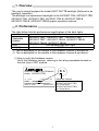
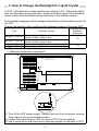
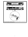
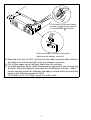
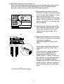
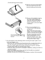
Model A9GT-70LTTB Back Light User’s Manual Thank you for purchasing the MELSEC-GOT Series. To ensure correct use of this equipment, please carefully read this manual prior to use. MODEL A9GT-70LTT-B-U MODEL 1DM117 CODE IB(NA)-80033-C(0406)MEE Mitsubishi Graphic Operation Terminal z SAFETY PRECAUTIONS z (Always read before starting use) Before using this product, please read this manual and the relevant manuals introduced in this manual carefully and pay full attention to safety to handle the product correctly. The precautions given in this manual are concerned with this product. For the safety precautions of the programmable controller system, please read the CPU module user's manual. In this manual, the safety precautions are ranked as "DANGER" and "CAUTION". DANGER CAUTION Indicates that incorrect handling may cause hazardous conditions, resulting in death or severe injury. Indicates that incorrect handling may cause hazardous conditions, resulting in medium or slight personal injury or physical damage. Note that the CAUTION level may lead to a serious consequence according to the circumstances. Always follow the precautions of both levels because they are important to personal safety. Please save this manual to make it accessible when required and always forward it to the end user. A-1 [HANDING PRECAUTIONS] DANGER z Before changing the backlight, always switch off the GOT power externally in all phases (when the GOT is connected to the bus, the PLC CPU power must also be switched off externally in all phases) and remove the GOT main unit from the enclosure. Not switching the power off in all phases may cause en electric shock. Not removing the unit from the enclosure can cause injury due to a drop. CAUTION z While changing the backlight, do not touch the circuit boards and electronic parts of the GOT. Doing so can cause a failure or malfunction. z When changing the backlight, always note the following. y Wear gloves or fingerstalls before starting the replacement of the backlight. Not doing so can cause injury. y Start changing the backlight more than 5 minutes after switching the GOT power off. Not doing so can cause a burn due to the heat of the backlight. [DISPOSAL PRECAUTIONS] CAUTION z When disposing, treat this product as industrial waste. A-2 Revisions Print Date Jan., 1999 Feb., 2003 Jun., 2004 * The manual number is noted at the lower left of the back cover. *Manual Number Revision IB(NA)-80033-A First printing IB(NA)-80033-B Partial additions Chapter 3 IB(NA)-80033-C Partial correction SAFETY PRECAUTION, Manuals, Chapter 2 MODEL CODE change Changed from 13JQ25 to 1DM117 This manual confers no industrial property rights or any rights of any other kind, nor does it confer any patent licenses. Mitsubishi electric Corporation cannot be held responsible for any problems involving industrial property rights which may occur as a result of using the contents noted in this manual. 1999 MITSUBISHI ELECTRIC CORPORATION A-3 CONTENTS 1. Overview .......................................................................................................1 2. Performance .................................................................................................1 3. How to Change the Backlight for Liquid Crystal .............................................2 A-4 Manuals The following manuals are relevant to this product. Refer to the following list and order the required manuals. Detailed Manual Manual name A985GOT/A975GOT/A970GOT/A960GOT User’s Manual (Available as option) Manual No. (Model code) SH-4005 (1DM099) Relevant Manual For relevant manual, refer to the PDF manual stored within the drawing software. A-5 1. Overview This user’s manual explains the model A9GT-70LTTB backlight (Referred to as backlight, hereafter). This backlight is a replacement backlight for the A975GOT-TBA, A975GOT-TBD, A970GOT-TBA, A970GOT-TBD, A975GOT-TBA-B, A975GOT-TBD-B, A970GOT-TBA-B, A970GOT-TBD-B graphic operation terminal. 2. Preformance The table below lists the performance specifications of the back lights. Item Specifications *1 A975GOT-TBA , A975GOT-TBD*2, A970GOT-TBA*1, Applicable A970GOT-TBD*2, A975GOT-TBA-B, A975GOT-TBD-B, models A970GOT-TBA-B, A970GOT-TBD-B Kind Cold cathode tube back light Life [Hr] 40,000 *1: This is applicable for the models of the hardware Version D and above. *2: This is applicable for the models of the hardware Version B and above. (1) How to verify the hardware version Verify the hardware version, referring to the rating nameplate bonded on the rear face of GOT module. GRAPHIC OPERATION TERMINAL MODEL A970GOT-TBD IN 24VAC DATE POWER MAX 115VA 9812 B A MITSUBISHI ELECTRIC CORPORATION MADE IN JAPAN BD992C032H16 1 BA Hardware Version Applicable hardware version A975GOT/A970GOT-TBA: Ver. D and above A975GOT/A970GOT-TBD: Ver. B and above 3. How to Change the Backlight for Liquid Crystal In GOT, back lights are incorporated for the indicator LCD. These back lights lose the luminance as they are used. Replace the back lights if the luminance lowers further than that affects the performance of the indicator screen. The backlight changing method changes depending on the hardware version of the GOT. Change the backlight after confirming the hardware version of the used GOT. Type A97 GOT-TBA(-B) A97 GOT-TBD(-B) A97 GOT-TBA(-B) A97 GOT-TBD(-B) Hardware Version Version K (May, 2001) or earlier, Version R (May, 2002) or later Version K (May, 2001) or earlier, Version Q (May, 2002) or later Version L (June, 2001) to Version Q (April, 2002) Version L (June, 2001 to Version P (April, 2002) Changing Method Reference Destination (1) (2) (1) Backlight replacement procedure 1 1) Turn off the GOT power supply. Remove the wire from the power terminal. Then remove the communications cable. 2) Loosen the metal fitting on GOT to remove GOT from the cabinet. 3) Use a screw driver and remove four fastening screws on the back of GOT. 2 Top part Bottom part 4) After removing the fastening screws, remove the indicator cover from GOT, while pressing two fastening hooks. 3 a nail -like b Lift the black nail-like part (black) towards the a direction, and pull it out towards the b direction. Remove the cable connector on the back lights from the indicator connector. 5) Show the front face of GOT, and remove the cable connector that is fitted to the upper one of the back lights from the indicator connector. 6) Pull out the upper one of the back lights from the indicator. 7) To install new back lights, follow the procedure opposite to that of removing. Similarly, follow the opposite procedure for installing the indicator. Make sure to securely install the indicator and apply a torque within the specified range to the fastening screws for GOT. 36 to 48N•cm (3.7 to 4.9kgf•cm)(3.2 to 4.2lb•inch) 4 (2) Backlight replacement procedure 2 Remove the screws recognizing each size during backlight replacement, since they have different sizes depending on the mounted positions. Be sure to store the screws by size after removing them. 1) Remove the connector cover for RS-232C interface, printer interface or communication module, if it has been mounted to the GOT. 2) Also, remove the wires connecting cable, various modules or terminal block to the GOT, if the wiring has been installed. 2) 2) Unscrew four fixing screws on the GOT rear side with a driver. (They cannot be completely removed.) (Tightening torque range: 36 to 48Nycm) GOT rear side GOT top side 3) Remove the display cover from the GOT while pressing four fixing tabs, which are situated on top/bottom/right/left sides of the GOT. GOT bottom side GOT GOT left side right side A flat cable is attached under the fixing tab on the top side of the GOT. Take care not to apply excessive force on the fixing tabs while pressing them with a driver or similar device. Failure to observe this instruction may damage them. Be sure not to apply excessive pressure on the GOT case, which is made of resin. Failure to observe this instruction may also damage them. (Continued on the next page) 5 (Continued from previous page) 4) Put the GOT on the liquid crystal display side. Keep the liquid crystal display away from scratch or dirt by laying a sheet 5) on the work table in advance. 6) 5) Remove two screws from the rear side. ((M2.6 screw)10 to 13Nycm) 6) Remove two screws from the rear side. ((M3 screw)18 to 24Nycm) Please note that the screws are different in size. GOT rear side 7) Put the liquid crystal display side up and then remove the cable connector for backlight. Remove the cable connector for backlight. 8) Remove four screws (chassis mounting screw) on the outmost side. (Tightening torque range: 36 to 8) 48Nycm) 8) (Continued on the next page) 6 (Continued from previous page) 9) Remove the liquid crystal display and circuit board from the rear case by holding up the top side. 10) Remove the backlights keeping the liquid crystal display up. Keep the liquid crystal display away from scratch or dirt by laying a sheet on the work table in advance. 11) Mount new backlight(s) in a reverse order to the removal a procedures. Then, mount the liquid crystal display, circuit board and display b cover in a reverse order as well. *1 Be sure to securely mount the Pull out the backlight in b direction liquid crystal display, circuit pressing the fixing tab (black) in a board and display cover, and direction. tighten the fixing screws within the specified torque range. *1: Pay full attention to the followings while mounting the liquid crystal, circuit board and display cover. y Insert the GOT connectors and terminals into the corresponding holes on the rear case when mounting liquid crystal and circuit board onto it. y Be sure to gently tighten the screws mentioned in 8) and 2), and then retighten them within the specified torque range. y Insert the cable connectors for backlights completely, making sure that it is correctly mounted. y Attach the display cover taking care that the flat cable is not pinched` between the GOT and display cover. y Remove the dust from the liquid crystal display or inside of the front panel. 7 Warranty Mitsubishi will not be held liable for damage caused by factors found not to be the cause of Mitsubishi; machine damage or lost profits caused by faults in the Mitsubishi products; damage, secondary damage, accident compensation caused by special factors unpredictable by Mitsubishi; damages to products other than Mitsubishi products; and to other duties. For safe use y This product has been manufactured as a general-purpose part for general industries, and has not been designed or manufactured to be incorporated in a device or system used in purposes related to human life. y Before using the product for special purposes such as nuclear power, electric power, aerospace, medicine or passenger movement vehicles, consult with Mitsubishi. y This product has been manufactured under strict quality control. However, when installing the product where major accidents or losses could occur if the product fails, install appropriate backup or failsafe functions in the system. Country/Region Sales office/Tel U.S.A Mitsubishi Electric Automation Inc. 500 Corporate Woods Parkway Vernon Hills, IL 60061 Tel : +1-847-478-2100 Brazil MELCO-TEC Rep. Com.e Assessoria Tecnica Ltda. AV. Paulista 1471, Conj. 308, Sao Paulo City, Sao Paulo State, Brazil Tel : +55-11-283-2423 Germany Mitsubishi Electric Europe B.V. German Branch Gothaer Strasse 8 D-40880 Ratingen, GERMANY Tel : +49-2102-486-0 U.K Mitsubishi Electric Europe B.V. UK Branch Travellers Lane, Hatfield, Herts., AL10 8XB,UK Tel : +44-1707-276100 Italy Mitsubishi Electric Europe B.V. Italian Branch Centro Dir. Colleoni, Pal. Perseo-Ingr.2 Via Paracelso 12, 20041 Agrate B., Milano, Italy Tel : +39-039-6053344 Spain Mitsubishi Electric Europe B.V. Spanish Branch Carretera de Rubi 76-80 08190 - Sant Cugat del Valles, Barcelona, Spain Tel : +34-93-565-3131 France Mitsubishi Electric Europe B.V. French Branch 25 Boulevard des Bouvets, F-92741 Nanterre Cedex, France TEL: +33-1-5568-5568 South Africa Circuit Breaker Industries LTD. Tripswitch Drive, Elandsfontein Gauteng, South Africa Tel : +27-11-928-2000 Country/Region Sales office/Tel Hong Kong Ryoden Automation Ltd. 10th Floor, Manulife Tower, 169 Electric Road, North Point, HongKong Tel : +852-2887-8870 China Ryoden Automation Shanghai Ltd. 3F Block5 Building Automation Instrumentation Plaza 103 Cao Bao Rd. Shanghai 200233 China Tel : +86-21-6475-3228 Taiwan Setsuyo Enterprise Co., Ltd. 6F., No.105 Wu-Kung 3rd.RD, Wu-Ku Hsiang, Taipei Hsine, Taiwan Tel : +886-2-2299-2499 Korea HAN NEUNG TECHNO CO.,LTD. 1F Dong Seo Game Channel Bldg., 660-11, Deungchon-dong Kangsec-ku, Seoul, Korea Tel : +82-2-3660-9552 Singapore Mitsubishi Electric Asia Pte, Ltd. 307 ALEXANDRA ROAD #05-01/02, MITSUBISHI ELECTRIC BUILDING SINGAPORE 159943 Tel : +65-6473-2308 Thailand F. A. Tech Co.,Ltd. 898/28,29,30 S.V.City Building,Office Tower 2,Floor 17-18 Rama 3 Road, Bangkpongpang, Yannawa, Bangkok 10120 Tel : +66-2-682-6522 Indonesia P.T. Autoteknindo SUMBER MAKMUR Jl. Muara Karang Selatan Block A Utara No.1 Kav. No.11 Kawasan Industri/ Pergudangan Jakarta - Utara 14440 Tel : +62-21-663-0833 India Messung Systems Put,Ltd. Electronic Sadan NO:111 Unit No15, M.I.D.C BHOSARI,PUNE-411026 Tel : +91-20-712-2807 Australia Mitsubishi Electric Australia Pty. Ltd. 348 Victoria Road, PostalBag, No 2, Rydalmere, N.S.W 2116, Australia Tel : +61-2-9684-7777 HEAD OFFICE : 1-8-12, OFFICE TOWER Z 14F HARUMI CHUO-KU 104-6212, JAPAN NAGOYA WORKS : 1-14, YADA-MINAMI 5-CHOME, HIGASHI-KU, NAGOYA, JAPAN When exported from Japan, this manual does not require application to the Ministry of Economy, Trade and Industry for service transaction permission. Specifications subject to change without notice. Printed in Japan on recycled paper.