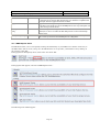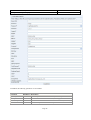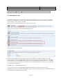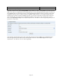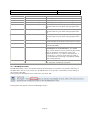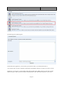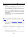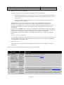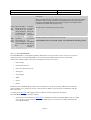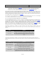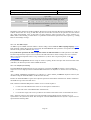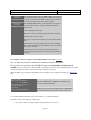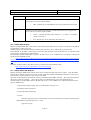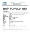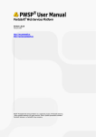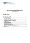
1
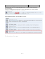
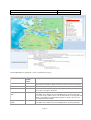
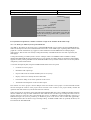
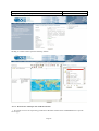
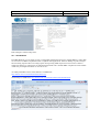
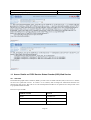
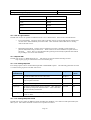
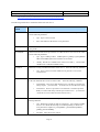
GEOSS Architecture Implementation Pilot, Phase 2 Testing Services Engineering Report 9. Version: 1.0 Date: 05/08/2009 ESA SSE Environment as a gateway for Web Services The WEB Services developers implementing the OGC Standards and the HMA Best Practices can be supported by the SSE environment not only to test their services during the development phase, but can also use the SSE to make them accessible to external users. Two kinds of SSE portals are available: • The SSE test portal (http://services-test.eoportal.org/index.jsp), • The SSE operational portal (http://services.eoportal.org/). The first portal is normally use for testing purposes, while the latter is to make available an operational service to external users. In order to do that the developer should be previously register on the SSE portal as service provider in order to be granted access and view its services published. 10. ESA SSE Providing HMA Open Software In the frame of the HMA Project ESA is collecting a library of Open Software that could be reused by the GEOSS Initiative. An entry point to this Open Software is provided at the following address: • http://wiki.services.eoportal.org/tiki-index.php?page=HMA%20Open%20Software. The following collections of software are provided: • EO SPS Library • HMA Skeleton • TEAM ENGINE • EO extension for WMS Reference Implementation • Conformance test scripts • GI-Cat Catalogue 10.1 EO SPS Library This open source project aims at building a JAVA API and library to help the implementation of the Earth Observation Profile of the OGC Sensor Planning Service (SPS). The EO SPS library is downloadable at http://code.google.com/p/eo-sps-library/. This open source project aims at building a JAVA API and library to help the implementation of the Earth Observation Profile of the OGC Sensor Planning Service (SPS). This EO-SPS profile is defined by the European Space Agency (ESA) within the HMA project. This library will provide implementers with an easy to use set of classes for parsing and writing task messages, feasibility studies, and acquisition status for space-borne optical and radar earth observation instruments. This project was initiated by Spot Image and relies on the OWS Service Framework, also on Google Code. The EO SPS demo page is available at the following address: • ws.spotimage.com/labs/HMADemoPage.htm. Page 38 GEOSS Architecture Implementation Pilot, Phase 2 Testing Services Engineering Report Version: 1.0 Date: 05/08/2009 10.2 HMA Skeleton The HMA Skeleton is a tool which provides a configurable simulation framework to simulate HMA (or other) Web services and to test HMA-compliant and OGC compliant client applications. It allows defining response messages and associating response files to incoming request messages using XPath expressions. The tool also contains a simple user interface to send requests to either the skeleton back-end or another HMA-compliant server the address of which is preconfigured in the list of "remote servers". Details on the Skeleton tool are available at http://wiki.services.eoportal.org/tiki-index.php?page=HMA+Skeleton. The software is downloadable at http://delucia.esrin.esa.int/skeleton/hma/web/Test.jsp and also an “on line help” is available at http://delucia.esrin.esa.int/skeleton/hma/web/sum/index.htm. The skeleton tool is also censed among the SSE tools at section 13.7. 10.3 TEAM ENGINE The ERGO project has contributed various extensions to the open-source TEAM engine which is used for conformance testing by the OGC. Compliance & Interoperability Testing & Evaluation (CITE) is an ongoing initiative of the OGC that develops tests for OGC standards, and makes those tests available for online testing on http://cite.opengeospatial.org/. In the framework of the ERGO project Intecs is updating the TEAM Engine to support the SOAP based HMA catalogue interfaces. The following functionalities have been added: • Support for SOAP (synchronous operations) • SOAP parser The resulting extension is not to be considered as the official TEAM Engine release. The approach used in the ERGO project is to be discussed at OGC level. The implementation is compliant with the new CTL specification which is now an OGC Best Practice document. The document can be downloaded from http://portal.opengeospatial.org/files/?artifact_id=33085&version=1. The modified TEAM engine can be downloaded from http://toolbox.esrin.esa.int/Download/teamengine/TEAMEngine2.zip . 10.4 EO extension for WMS Reference Implementation The HMA-T project has published a reference implementation for OGC 07-063 EO Extension for WMS. The implementation will eventually be contributed to the MapServer source base. The HMA-T WMS for EO Profile uses two perl scripts, a modified version of UMN Mapserver, and PostgreSQL with PostGIS. The default installation has the cgi-bin directory at /var/www/cgi-bin, mapserver at /var/mapserver, and the sample data at /var/mapserver/data. If any of these locations change then the perl scripts and possibly the database will need to be altered to reflect the new locations. The EO extension for WMS can be downloaded from http://hma01.infoterra.co.uk/HMA-T/deliverable/2009-0605/hma_deliverables.tgz . 10.5 Conformance test scripts The HMA-T project makes available Conformance test language (CTL) scripts for various HMA specifications. They are maintained on an SVN server managed by the Open Geospatial Consortium. Page 39 GEOSS Architecture Implementation Pilot, Phase 2 Testing Services Engineering Report Version: 1.0 Date: 05/08/2009 The delivery of these scripts will come soon. 10.6 GI-Cat Catalogue The GI-cat catalogue extensions from CNR-IMAA provides an open-source reference implementation of the Earth Observation Extension Package OGC 06-131 and the CIM Extension package OGC 07-038 for CSW ebRIM Application Profile. GI-cat is an implementation of distributed catalog services made by ESSI Lab: • Allows clients to discover and evaluate geoinformation resources over a federation of data sources; • Allows different clients to use the service, as it publishes different catalog interfaces. A data provider can deploy his/her own GI-cat instance, grouping together disparate data sources, to accommodate his/her user needs. GI-cat features caching and mediation capabilities and can act as a broker towards disparate catalog and access services: by implementing metadata harmonization and protocol adaptation, it is able to transform query results to a uniform and consistent interface. GI-cat is based on a service-oriented framework of modular components and can be customized and tailored to support different deployment scenarios. GI-cat is downloadable from http://zeus.pin.unifi.it/cgi-bin/twiki/view/GIcat . 11. ESA SSE VIDEO TUTORIAL The European Space Agency has made available some HMA videos at http://wiki.services.eoportal.org/tikiindex.php?page=HMA%20Videos. A first video (http://www.youtube.com/watch?v=DvhJM2cw2T4 ) shows the basic concepts of Heterogeneous Mission Accessibility . Another video (http://www.youtube.com/watch?v=sjmZ3FoCeOE ) shows the HMA EO profile for WMS. The interested reader can also access directly the “HMA-T Phase 2 demonstration of EO Profile of WMS” on the SSE test portal at http://services-test.eoportal.org/portal/service/ShowServiceInfo.do?serviceId=FA809080. 12. ESA SSE Calibrated and Pre-Classified EO Products for CAT-1 Users The European Space Agency has made available several EO services through the SSE portal http://services.eoportal.org/ . Page 40 GEOSS Architecture Implementation Pilot, Phase 2 Testing Services Engineering Report Version: 1.0 Date: 05/08/2009 Accessing the Data and Information provision services panel, for example the user can access the ESA CAT-1 Services; similarly accessing the Thematic Services the user can access the Land Management Services. 13. Annex: Details on ESA Tools 13.1 GML/SLD Tester Page 41 GEOSS Architecture Implementation Pilot, Phase 2 Testing Services Engineering Report Version: 1.0 Date: 05/08/2009 The SSE Portal offers you a tool for quickly checking the correctness of your GML Samples and Styled Layer Descriptor (SLD) files. If you log on to the SSE Portal as service provider, you find these tools by clicking on the "software" quick link. In the page that is subsequently shown, click on the "Test Tools" link. In the page that then appears, select the "GML/SLD Tester". The following form will then appear: Page 42 GEOSS Architecture Implementation Pilot, Phase 2 Testing Services Engineering Report Version: 1.0 Date: 05/08/2009 In this GML/SLD tester application, you have the following controls: Control Name Start Viewer Before/after starting Viewer N/A Clear Service Results Select SR Id After After Display Service Result GML After Display WFS Features (GML) After Description Button that starts the WebMapViewer with the configuration string and/or Web Map Context string that are defined in the text boxes at the bottom of the page. Clears the map by removing all previously loaded Service Results Select the service result feature characterised by the identifier that is given in the text box to the right of the button. Loads the GML String that is present in the text box to the right of the button. If the GML can be understood by the WebMapViewer, the map will update, else an alert message will be shown. Use this functionality for testing GML that adheres to the SSE Service Result GML Application schema. (Not for more general Simple Features GML). Loads the GML String that is present in the text box to the right of the button. If the GML can be understood by the WebMapViewer, the map will update, Page 43 GEOSS Architecture Implementation Pilot, Phase 2 Testing Services Engineering Report Apply SLD After Startup WMS Context string Before Startup Config string Before Version: 1.0 Date: 05/08/2009 else an alert message will be shown. Use this functionality for testing GML that is derived from for instance Web Features Services and that is compliant with the Simple Features Application Profile of GML. Applies the SLD string that is present in the text box to the right of the button. If the SLD can be understood by the WebMapViewer, the map will update, else an alert message will be shown. The Web Map Context string that determines which OGC WMS, WFS, WCS, SOS layers to show. Overrides the Web Map Context section in the Startup Config string. The Configuration string that one can use for configuring the WebMapViewer. This can be exported from the WebMapViewer Configurator. 13.2 WMS Request Tester The SSE Portal offers you a tool for quickly checking the functionality of your WMS service and the connectivity of the SSE Portal to this service. If you log on to the SSE Portal as service provider, you find these tools by clicking on the "software" quick link. In the page that is subsequently shown, click on the "Test Tools" link. In the page that then appears, select the "WMS Request Tester". The following form will then appear: Page 44 GEOSS Architecture Implementation Pilot, Phase 2 Testing Services Engineering Report Version: 1.0 Date: 05/08/2009 In this WMS tester application, you first need to paste the base URL to your Web Map Service. (This is typically the URL of your Web Application ending with a question mark. Note however that for some Web Map Service products (for example ESRI ArcIMS) you may need to add additional parameters after the "?" to indicate the map service that you want to test. You then need to append an additional key-value pair to the base URL (e.g.ServiceName = MyService). Leave the "Service" type unchanged to WMS. You can then select out of the dropdownbox which WMS operation (or request) you want to execute. Depending on your choice, the window will update and show you the parameters that can be submitted. Parameters that are mandatory are marked with an asterisks. Typically you first execute a WMS GetCapabilities request. When you select "GetCapabilities" from the dropdown listbox you will see two additional text boxes appearing where you can optionally specify the specific section out of the capabilities that you would want to retrieve or the UpdateSequence Number to retrieve a specific version of the Capabilities. When you click on submit, either the Capabilities XML document or an exception will be shown in another browser window. From the Capabilities response you can discover the following information that you need in order to construct valid GetMap requests: • The WMS Layer names • The supported Coordinate Reference Systems • The spatial extent of your service • The supported image formats • The names of the styles for each of these layers You then select GetMap from the request dropdown box. You will see a number of new text boxes appearing that you need to fill with appropriate values: Page 45 GEOSS Architecture Implementation Pilot, Phase 2 Testing Services Engineering Report Version: 1.0 Date: 05/08/2009 The following parameters (in addition to SERVICE, VERSION and REQUEST) are to be filled: Parameter LAYERS Mandatory Description Y Comma separated list of the WMS Layer NAMES (not titles) as discovered from the capabilities. STYLES Y Comma-separated list of one rendering STYLE per requested layer. (Note that the WMS specification makes this mandatory but a lot of service implementations do not require this.) SRS Y The Spatial Reference System (SRS) BBOX Y The Bounding Box corners expressed as "minX,minY,maxX,maxY" in SRS units. WIDTH HEIGHT Y Y Width in pixels of map picture. Height in pixels of map picture. FORMAT Y Output format of map. Typically expressed as MIME type e.g. image/png. Page 46 GEOSS Architecture Implementation Pilot, Phase 2 Testing Services Engineering Report Version: 1.0 Date: 05/08/2009 TRANSPARENT N Background transparency of map: TRUE or FALSE (default=FALSE). BGCOLOR N Hexadecimal red-green-blue colour value for the background color (default=0xFFFFFF). TIME ELEVATION N N Time value for the layer(s). Elevation value for the layer(s). EXCEPTIONS N The format in which exceptions are to be reported by the WMS (default=XML). SLD N URL of Styled Layer Descriptor (as defined in SLD Specification) (WMS 1.1.1 SLD-WMS). WFS N URL of Web Feature Service providing features to be symbolized using SLD (WMS 1.1.1 SLD-WMS). Vendor-specific N Optional vendor-specific experimental parameters. Insert Key-value pairs of parameters and values. You then can select GetFeatureInfo from the request dropdown box. This will allow you to retrieve information about a specific point on the map. Note that is an optional operation that not all Web Map Servers do support and not necessarily on all layers as this is typically only used for vector data stores. • To find out whether a Web Map Service supports the GetFeatureInfo operation, check within the GetCapabilities whether a element appears under the section. • To find out whether the GetFeatureInfo operation is supported for a particular layer, check the queryable attribute for this layer in the WMS Capabilities. After selecting GetFeatureInfo from the request dropdown box, you will see a number of new text boxes appearing that you need to fill with appropriate values: Note that you will also see the parameters that were required when specifying the GetMap requests, this is because a "partial copy of the Map request parameters that generated the map for which information is desired" needs to be submitted. Page 47 GEOSS Architecture Implementation Pilot, Phase 2 Testing Services Engineering Report Version: 1.0 Date: 05/08/2009 In addition, the following parameters are to be filled: Parameter Mandatory Description QUERY_LAYERS Y Comma-separated list of one or more layers to be queried. INFO_FORMAT Y Return format of feature information (MIME type). FEATURE_COUNT N Number of features about which to return information (default=1). I i coordinate in pixels of feature in Map Coordinates. Y Page 48 GEOSS Architecture Implementation Pilot, Phase 2 Testing Services Engineering Report J Y Version: 1.0 Date: 05/08/2009 j coordinate in pixels of feature in Map Coordinates. 13.3 WCS Request Tester The SSE Portal offers you a tool for quickly checking the functionality of your Web Coverage Service and the connectivity of the SSE Portal to this service. If you log on to the SSE Portal as service provider, you find these tools by clicking on the "software" quick link. In the page that is subsequently shown, click on the "Test Tools" link. In the page that then appears, select the "WCS Request Tester". The following form will then appear: In this WCS tester application, you first need to paste the base URL to your Web Coverage Service. (This is typically the URL of your Web Application ending with a question mark. Note however that for some Web Map Service products (for example ESRI ArcIMS) you may need to add additional parameters after the "?" to indicate the coverage service that you want to test. You then need to append an additional key-value pair to the base URL (e.g.ServiceName = MyService). Leave the "Service" type unchanged to WCS. You can then select out of the dropdownbox which WCS operation (or request) you want to execute. Depending on your choice, the window will update and show you the parameters that can be submitted. Parameters that are mandatory are marked with an asterisks. Page 49 GEOSS Architecture Implementation Pilot, Phase 2 Testing Services Engineering Report Version: 1.0 Date: 05/08/2009 Typically you first execute a WCS GetCapabilities request. When you select "GetCapabilities" from the dropdown listbox you will see two additional text boxes appearing where you can optionally specify the specific section out of the capabilities that you would want to retrieve or the UpdateSequence Number to retrieve a specific version of the Capabilities. When you click on submit, either the Capabilities XML document or an exception will be shown in another browser window. From the Capabilities response, you can discover the WCS coverage names (with some other metadata) that you can then use for submitting DescribeCoverage requests. Once you know the coverage names, select DescribeCoverage from the request dropdown box. You will see a new box appearing where you can specify the coverage name. After analysing the DescribeCoverage results, and noting down the envelopes (BBOX), the available bands and times, the supported response CRS, formats and interpolation methods, select GetCoverage from the request dropdown box. You will see a new set of boxes appearing: Page 50 GEOSS Architecture Implementation Pilot, Phase 2 Testing Services Engineering Report Version: 1.0 Date: 05/08/2009 The following parameters (in addition to SERVICE, VERSION and REQUEST) are to be filled: Parameter COVERAGE CRS Mandatory Y Y RESPONSE_CRS N BBOX One of BBOX or TIME is required. One of BBOX or TIME is required. TIME Description Name of an available coverage. Coordinate Reference System in which the request is expressed. Coordinate Reference System in which to express coverage responses. Optional as it defaults to the request CRS. The Bounding Box corners expressed as "minX,minY,maxX,maxY,minZ,maxZ" in CRS units. Request a subset corresponding to the specified time instants or intervals, expressed in an extended ISO 8601 syntax. Optional if a default time (or fixed time, or no Page 51 GEOSS Architecture Implementation Pilot, Phase 2 Testing Services Engineering Report Version: 1.0 Date: 05/08/2009 WIDTH HEIGHT DEPTH RESX WIDTH or RESX is required. HEIGHT or RESY is required. DEPTH or RESZ is required WIDTH or RESX is required. RESY HEIGHT or RESY is required. RESZ DEPTH or RESZ is required FORMAT Y EXCEPTIONS N PARAMETER Optional if default values exist Vendor-specific N time) is de-fined for the selected layer. Width (in grid points or) pixels of the coverage Height (in grid points or) pixels of the coverage Depth (in grid points or) pixels of the coverage Specific spatial resolution along the X axis of the reply CRS. The values are given in the units appropriate to the axis. Specific spatial resolution along the Y axis of the reply CRS. The values are given in the units appropriate to the axis. Specific spatial resolution along the Z axis of the reply CRS. The values are given in the units appropriate to the axis. Requested output format of Coverage. Must be one of those listed under the description of the selected coverage. The format in which exceptions are to be reported by the WCS (default=XML). Request a range subset defined by constraining parameter PARAMETER. The PARAMETER key is a variable string; it must match the name of a parameter listed in the range set description of the selected coverage. For instance: band=1,5,3 (e.g., radiance values in bands 1, 5, 3) age=0/18 (e.g., counts of people with ages under 18 yrs.) Optional if the chosen range component has default values for the parameter. Optional vendor-specific experimental parameters. Insert Key-value pairs of parameters and values. 13.4 WFS Request Tester The SSE Portal offers you a tool for quickly checking the functionality of your WFS service and the connectivity of the SSE Portal to this service. If you log on to the SSE Portal as service provider, you find these tools by clicking on the "software" quick link. In the page that is subsequently shown, click on the "Test Tools" link. In the page that then appears, select the "WFS Request Tester". Page 52 GEOSS Architecture Implementation Pilot, Phase 2 Testing Services Engineering Report Version: 1.0 Date: 05/08/2009 The following form will then appear: In this WFS tester application, you first need to paste the base URL to your Web Feature Service. You can then select out of the "Template" dropdownbox which WFS operation (or request) you want to execute. In function of your choice, a specific XML sample will be loaded. These XML samples are the bodies of WFS POST messages in which you need to replace certain parameters with values that are specific to your service. Page 53 GEOSS Architecture Implementation Pilot, Phase 2 Testing Services Engineering Report Version: 1.0 Date: 05/08/2009 An in depth discussion of these requests can obviouly be found in the Web Feature Service and Filter Specifications of the OGC. Some hints: • Typically you first execute a WFS GetCapabilities request. You can use the template as it is. From the capabilities that are returned, you need to note down the FeatureType names for further use. • You then load the WFS DescribeFeatureType request template. In this template you replace TYPE1 and/or TYPE2 with valid TypeNames for your WFS. Alternatively you can remove these elements. From the DescribeFeatureType response, you then need to note the propertyNames that are of interest to you. • You then load the WFS GetFeature request template. In there you need to replace TYPE1 with a valid typeName for your server. The TYPE1.PROP1 indicates the attribute (property) that you want the WFS server to return. You then need to specify a valid Filter statement in which you can have lots of variations. If you want to use the template, replace the "Operator" with a valid Filter operator as PropertyIsEqualTo, replace TYPE1.PROP2 by a valid propertyName for your FeatureType and replace VAL1 with a realistic value for this propertyType. • For using the Transactional operations, you then load the WFS LockFeature and Transactional (Insert, Update, Delete) request templates with replacement of parameters as TYPE1, VAL1, ID1,... with appropriate values for your WFS. 13.5 SSE Toolbox The TOOLBOX has been developed under the SSE project. SSE integrates service providers (having variety of component models or middle-ware suited for their different platforms or environments) through XML, i.e. using SOAP and WSDL transported over a variety of transport mechanisms, i.e. IP, HTTP, and HTTPS. Thus, any service to be integrated within the SSE infrastructure must expose a SOAP interface (described by a WSDL file) according to the SSE Interface Control Document (SSE ICD). The TOOLBOX helps the service provider to convert its service in a SOAP based service compliant with the SSE ICD. The Toolbox is composed by two application, a development environment and a run-time environment • The run-time environment is a web application which allows the deployment of SOAP interfaces compliant with the SSE ICD by means of some XML scripts which describe the operations that have to be done when the service is invoked • The development environment is an Eclipse plugin which provides some tool to easily creates the TOOLBOX services, editing its script files and resources. The run-time and development environment can be used separately. The XML scripts can be created with any tool supporting XML or with a text editor (the scripts have to be compliant to the XMLScript Schema). 13.5.1 Integrate services into the SSE framework How to integrate services in the SSE framework can be found in the SSE ICD. Here is provided an excerpt. 1. Define the schema of the service to be integrated into the SSE The Service Provider should define the XML schema for his service. To do that, he has to answer to the following questions: Page 54 GEOSS Architecture Implementation Pilot, Phase 2 Testing Services Engineering Report Version: 1.0 Date: 05/08/2009 o Does my service needs an Area Of Interest as input parameter? o Does my service results contain geographical information to be displayed on a Web Map viewer ? o Does my service need a Request For Quotation function in order to give some information on price or on the different items available? o What is the information needed by my service to be able to answer to an RFQ or an Order request ? o What is the result of the RFQ and the Order ? o For each operation, is my system able to return immediately (synchronous communication) the response and does it need some time to process the request (asynchronous communication)? The answer to all these questions should be formalized in the XML service schema following the conventions described in the current document (SSE ICD). 2. Select one of the integration mechanisms provided by the SSE TOOLBOX RE(this step applies only to basic services integration). See below 3. Integrate the Service with the Toolbox RE(this step applies only to basic services integration) According to the selected integration mechanism and the service schema : 4. o Install the SSE TOOLBOX RE o Create the XML scripts describing the operations the TOOLBOX RE must perform any time it receives a request incoming from the SSE portal o Configure the SSE TOOLBOX RE to integrate the service o If needed, implement the glue between the TOOLBOX RE and the service. Become a Service Provider If you are not yet a registered user, go on the SSE Portal: o Register yourself on the SSE Portal o Login on the SSE Portal o Update your profile and apply to become a Service Provider o After the SSE administrator e-mail confirmation, register your company on the SSE Portal. o From now, you can follow the “Monitor Orders” link to login into the Oracle Workflow monitoring tool using the same account than the one used to login on the SSE Portal. For the details concerning these operations, see the online SSE user manual available following the “help” link on the SSE site (chapters “User Commands” and “Service Provider Commands”). 5. Design you service workflow (this step only applies if your service is a chained service) If your service is a basic service, the default workflow can be used (see next step). o Download the Oracle BPEL Designer tool from the software section of the SSE Portal http://services.eoportal.org/portal/DownloadUtil.jsp while logged in as Service Provider. o Design your workflow. Page 55 GEOSS Architecture Implementation Pilot, Phase 2 Testing Services Engineering Report 6. Version: 1.0 Date: 05/08/2009 Register your service on the SSE Portal In order to prepare your service registration on the SSE Portal, you should define: o the WSDL file describing your service based on your service schema definition. The WSDL file will be automatically generated by the SSE Toolbox RE. (This step applies only if your service is a basic service.) o the style sheet that will allow to handle your service specific input and output parameters (as defined in your service schema). When these files are ready, you can register your service based on the SSE Portal. In the service registration form, set the status of your service to “testing” so that only you can order the service. If your service is a basic service, in the service registration page, select the default workflow for each operations implemented by your service. Don't forget to specify if the operations are synchronous or asynchronous. If your service is a chained service, in the service registration page, the workflow you have just deployed will appear in the workflow selection lists. Select the workflow associated to each operations implemented by your service. Don't forget to specify if the operations are synchronous or asynchronous. For the details concerning these operations, see the SSE tutorial following the “help” link on the SSE Portal. 7. Test your service on the SSE Portal Go to the SSE service directory and check that you can retrieve your service and the associated description. Test the integration of your service with the SSE Portal by ordering your service following the different steps if applicable : Search, RFQ, Order. 8. Publish your service When your service is operational, you can change the status of your service to “enable” on the Service Update page. In brief, here is the file list required by the integration of a service within SSE: File Description service defines the schema structure and the content of the payload of the SOAP messages exchanged between the TOOLBOX RE and the SSE Use it must be provided to the SSE during the service registration and to the TOOLBOX RE during the service creation WSDL describes the it must be file SOAP interface of provided to the service based the SSE on service schema during the definition service registration File creation this file must be created by the service provider. Help on creation can be found in SSE ICD . this file is automatically created by the TOOLBOX RE during the service creation if the service provider inserts all the required information (see the service management section). The file can be find on the TOOLBOXmachine at the following URL: http://<TOMCAT_HOST>[:TOMCAT_PORT]/TOOLBOX/WSDL/<SERVICE_NAME>/<SERVICE_NAME>.wsdl where <TOMCAT_HOST> is the host where the TOMCAT hosting the TOOLBOX RE is Page 56 GEOSS Architecture Implementation Pilot, Phase 2 Testing Services Engineering Report Version: 1.0 Date: 05/08/2009 installed on. Before providing this file to the SSE Portal, the service provider must check whether this file has been correctly created by the TOOLBOX RE, indeed, if the machine hosting the TOOLBOX RE has not been well-configured some HTTP address contained in the WSDL file might be wrong. Service allows the SSE to style handle the service sheet specific input and output parameters (as defined in the service schema) service describe(s) the XML operations script performed by the file(s) service deployed on the TOOLBOX RE. it must be this file must be created by the service provider. provided to the SSE during the service registration it must be this file(s) must be created by the service provider. provided to the Understanding of the service XML scripts can be found in the following sections. TOOLBOX RE during the service creation 13.5.1.1 The TOOLBOX RE. The TOOLBOX RE is a configurable application that help the Service Provider to easily convert its service into a SOAP based service. The TOOLBOX RE can be used to integrate different kind of services into the SSE infrastructure. Different kinds of back-end communication systems are foreseen: • File exchange • File Transfer Protocol • Hyper Text Transfer Protocol • API support • Script support • JDBC • SOAP • Email Furthermore the TOOLBOX RE provides an easy mechanism to convert the incoming XML files into other files (based on XML or on a proprietary format) or data structures suitable to be used for the communication with the back-end systems. According to the SSE ICD, SSE supports both a synchronous and an asynchronous mechanism. The TOOLBOX RE supports both the solutions: • Synchronous: in this solution, the SSE Portal is a SOAP client and the TOOLBOX RE acts only as a SOAP server. It only responds to SOAP requests. The XML response is sent back to the SSE Portal during the same HTTP exchange. Page 57 GEOSS Architecture Implementation Pilot, Phase 2 Testing Services Engineering Report • Version: 1.0 Date: 05/08/2009 Asynchronous: in this solution, the SSE Portal is a SOAP client as well as a SOAP server. The service provider sends a SOAP message back to SSE when a result is ready. Thus the TOOLBOX RE implements a SOAP server as well as a SOAP client. The TOOLBOX RE uses the WS-Addressing protocol. The approach used to build a configurable application that will help the Service Provider to easily convert its service into a SOAP based service is based on XML scripting. In order to convert a legacy Service into a SOAP service suitable to be plugged into the SSE framework the Service Provider has to provide one or three XML scripting files. These files will describe the operations needed to complete a request coming from SSE. More details about the service XML Script(s) can be found in the section "Tutorial". The configuration of the TOOLBOX RE, as well as the configuration and monitoring of the services, occur through the “TOOLBOX ADMINISTRATOR” Web application coming with the TOOLBOX RE. 13.5.1.2 Services and operations deployed on the TOOLBOX RE. From the TOOLBOX RE perspective, a service is a collection of operations. Each operation is associated with one or several XML script files (which must be valid according to the TOOLBOX XML scripting language schema), depending on the mode the operation is published (synchronous or asynchronous). Further any operation is associated with a "soapAction": any HTTP request including a SOAP request for a certain operation must have the HTTP header "SOAPAction" set to that string value. Each operation can be compliant with the SSE ICD and EOLI ICD or not. This means that the TOOLBOX RE can be used also to deploy services outside from the SSE framework. Each service can support contemporary both SSE compliant and not SSE compliant operations. Synchronous operations have a number of 2 scripts associated to them. These must be provided in order to let Toolbox Runtime Environment execute all tasks. The scripts are referred to with the following name and have these function: Script First script Error script Function Main script for the synchronous operation. Executed as soon as the message is received. This script shall return an XML type object. This script is executed every time the main script exits for an error. This script should return an Interface specific error message to the client. Asynchronous operation have a number of 6 scripts associated to them. These must be provided in order to let Toolbox Runtime Environment execute all tasks. The scripts are referred to with the following name and have these function: Script Response builder script Response Builder Error First script Second script Function This script is executed as soon as the input message is received. It creates the acknowledge message to be sent back. This script is executed every time an error occurs during the response builder script execution. It is used to return an interface compliant error message to the client. This is the first script executed just after the response builder. It should be used to perform all main tasks. This script is executed until it return a "TRUE" boolean value. This script should be used to check all operation condition before completing the execution. This script shall always return a Boolean Page 58 GEOSS Architecture Implementation Pilot, Phase 2 Testing Services Engineering Report Third script Error script Version: 1.0 Date: 05/08/2009 type value This script is used to create the response message to be sent back to the client. This script shall return an XML type object. This script is executed every time the main script exits for an error. This script should return an Interface specific error message to the client. Depending on the situation the Toolbox Runtime Environment or Development Environment should show or ask for a subset of these files. It is wrong to think that only those are the files associated to the operation since the software may supply automatically some of these files for those interfaces whose messages have a static structure (e.g. HMA). These automatically provided file have a predefined structured that peforms the task required (e.g. sending back an acknowledge message). 13.5.1.3 The XML scripts An XML script is an XML document which is valid according to the TOOLBOX XML scripting language schema. This document contains the operations performed by the TOOLBOX RE. The operations correspond to the tag elements of the grammar defined by the schema. For synchronous operations the XML script must return an XML Document. For SSE operations, such XML Document represents the response to be sent back to the SSE and must be valid according to the service schema. What a script returns depends on the root tag contained in it (to know what a tag returns please see the Tag documentation). For asynchronous operations: the First script can return everything, the Second script must return a Boolean value (true/false), the Third script must return an XML Document. 13.5.1.4 Request processing The TOOLBOX RE distinguishes the service recipient of a request by the URL the request is sent to. Indeed a request for a service deployed on the TOOLBOX RE with the name of "MyService" must be sent to the following URL: "http://<HOST_ADDRESS>/TOOLBOX/services/MyService" (where <HOST_ADDRESS> depends on the way the machine hosting the TOOLBOX RE is visible from the network). Further, the TOOLBOX RE recognizes the requested operation from the HTTP "SOAPAction" header contained in the HTTP message sent to the URL above. Thus, what the TOOLBOX RE performs when it receives a SOAP request is: 1. to extract from the URI the name of the service the request is addressed to; 2. to extract the value of the HTTP header "SOAPAction"; 3. to execute the script(s) the service provider has associated to that SOAP Action for the addressed service. Step 3. depends on the way the operation (associated with the extracted SOAP Action) is deployed, i.e. in synchronous or in asynchronous mode. The description of the TOOLBOX RE behavior any time a request arrives is reported in the following table: Page 59 GEOSS Architecture Implementation Pilot, Phase 2 Testing Services Engineering Report Version: 1.0 Date: 05/08/2009 synchronous operations The TOOLBOX RE executes the XML script corresponding to the operation and returns the response (as built in the script, if no error occurs) in the same HTTP exchange. If the execution exits with an exception the error script is executed. asynchronous operations The TOOLBOX RE returns an "acknowledgment" response to the client. This message is created executing the Response builder script. Start executing the First script. If the First script is successful, the Second script is executed. If the Second script is executed: If no error occurs the Second Script is executed until it returns true; If the Second script successfully returns true, the TOOLBOX RE executes the Third script and sends the response (as built in the script) to the client. In all these cases if an exception is thrown the global error script is executed creating an error message to be sent back to the client. For examples of services to deploy to the TOOLBOX RE see the section "Tutorial". 13.5.1.5 XML script execution: persistence of variables and cleanup mechanism. For asynchronous operations, the TOOLBOX supports the persistence of some types of variable among the executions of the three XML scripts related to the same request (identified by the messageId contained in the SOAP Header of the SOAP message containing the request). Within an XML script, creation and manipulation of the variables occurs through the following two XML Script tags: <setVariable name="variableName"> <!-- element returning an object --> </setVariable> <variable name="variableName"/> Sets the variable named "variableName" with the value given by the enclosed element Returns the object stored in variable named "variableName". If nothing has been stored with that name, it returns null. So, a variable defined in the First script can be referred, e.g., in the Second Script. Persistence concerns the following variable types: • byte (whose value is an integer number comprised between -27 and 27-1) Page 60 GEOSS Architecture Implementation Pilot, Phase 2 Testing Services Engineering Report Version: 1.0 Date: 05/08/2009 • short (whose value is an integer number comprised between - 215 and 215-1) • integer (whose value is an integer number comprised between – 231 and 231-1) • long (whose value is an integer number comprised between – 263 and 263-1) • float (largest positive finite value: (2-2-23)·2127, smallest positive nonzero value: 2-149) • double (largest positive finite value: (2-2-52)·21023, smallest positive nonzero value: 2-1074) • char (16-bit Unicode character) • boolean (true/false) • string • XML Document The TOOLBOX supports a cleanup mechanism allowing the service provider to specify the wished status in case of failure of a script. This mechanism foresees the use of three XML Script tags: <cleanupProcedure> <cleanup marker="Marker_One"> . . </cleanup> <cleanup marker="Marker_Two"> . . </cleanup> <cleanup marker="Marker_Three"> . . </cleanup> </cleanupProcedure> <addCleanupMarker value="A_Marker"/> The <cleanupProcedure> tag is a sequence of <cleanup> tags. Any <cleanup> tag encloses an element containing the operation(s) to be executed in case of failure. If the optional “marker” attribute is specified, the execution is subordinated to the existence of such marker (see <addCleanupMarker> and <removeCleanupMarker>), otherwise the execution occurs in any case. It is used to mark a point of a script whose achievement is required by the execution of the related <cleaunup> tag. For example, let’s suppose the deletion of a file created during the execution of the First script is wished in case of failure: the execution of the <cleanup> tag deleting that file must occur only if the file was created, i.e. the failure occurred after its creation. EXAMPLE of First script: <sequence xmlns="http://pisa.intecs.it/mass/toolbox/xmlScript"> . . Page 61 GEOSS Architecture Implementation Pilot, Phase 2 Testing Services Engineering Report Version: 1.0 Date: 05/08/2009 <setVariable name="fileName"> <string>/home/toolbox/request.xml</string> </setVariable> <dumpXML> <variable name="fileName"/> <xmlRequest/> </dumpXML> <addCleanupMarker value="A_Marker"/> . . <cleanupProcedure> <cleanup marker="A_Marker"> <fileDelete> <variable name="fileName"/> </fileDelete> </cleanup> <cleanup marker="Another_Marker"/> </cleanupProcedure> </sequence> Existence of the "A_Marker" marker ensures existence of the file named "fileName". <removeCleanupMarker value="A_Marker"/> This tag removes a tag previously added. It is used to mark a point of a script (First, Second, Third) whose achievement removes the need to execute the cleanup tag(s) associated with that marker. EXAMPLE. <sequence xmlns="http://pisa.intecs.it/mass/toolbox/xmlScript"> . . <setVariable name="fileName"> <string>/home/toolbox/request.xml</string> </setVariable> <dumpXML> <variable name="fileName"/> <xmlRequest/> </dumpXML> <addCleanupMarker value="A_Marker"/> . . <fileDelete> <variable name="fileName "/> </fileDelete> <removeCleanupMarker value="A_Marker"/> . . <cleanupProcedure> <cleanup marker="A_Marker"> Page 62 GEOSS Architecture Implementation Pilot, Phase 2 Testing Services Engineering Report Version: 1.0 Date: 05/08/2009 <fileDelete> <variable name="fileName"/> </fileDelete> </cleanup> <cleanup marker="Another_marker"/> </cleanupProcedure> </sequence> In this case the send script itself foresees the deletion of the file named "fileName": if the failure occurs after the deletion the cleanup tag marked with "A_Marker" must not be executed. For asynchronous operations, a marker created in a script can be used also in the other script. 13.5.1.6 Writing an XML script using TOOLBOX DE Any XML or Text editor can be used to write a valid TOOLBOX XML script to deploy into the TOOLBOX RE. To reduce the development time, the TOOLBOX DE can be used to create XML scripts, exploiting built-in features like graphical vs textual visualization, tag suggestion, online validation. The TOOLBOX DE is an Eclipse plugin, wirtten in Java, that extends some already existing functionality of the IDE itself and some other exported by the WTP plugin. Coming functionality, provided by future versions of Eclipse, WTP or TOOLBOX will be available to already installed TOOLBOX DE through powerful and easy to use upgrade procedures. Built over the Eclipse functionality, upgrade an already existing installation of the TOOLBOX DE is an easy and fast task that removes also the problem of dependecy check and download. A common development path, using the TOOLBOX DE, follows these few points: • Creation of a service project. • Definition of all scripts logic. • Import of all resources and files needed by the service (if any) • Deploy of the service directly into the Toolbox RE. • Execution or debug of one of the operations of the service. • Visualization and inspection of the execution output. The creation of a service project is done in Eclipse in the same manner a Java project is created. Wizards lead the end user through the creation of the project and its structure. Once created, a new project already contains all operations files and schema set (if an interface has been selected). Scripts and resources documents can be edited through TOOLBOX DE using some available functionality that help the user validate the script (an online validation is done while the user write the script, warning him when errors are present), find errors (each error discovered through the process of validation is marked graphically), insert tag or attributes through a list (a list of possible tag or attribute is ginven to the user in order to select them graphically). All editing features, like Cut Paste & Copy and Drag & Drop, available in XML editor (an generally in editors) can be found into the TOOLBOX DE. Page 63 GEOSS Architecture Implementation Pilot, Phase 2 Testing Services Engineering Report Version: 1.0 Date: 05/08/2009 The TOOLBOX DE allows the final user to test one operation at time even if each TOOLBOX DE service project can contain a potentially unlimited number of operations. If more than one operation have been created into a service project, it is possible to run and debug them singularly creating a launch configuration for each one. A normal execution (run) of an operation is done quickly clicking on a launch configuration on the Run submenu. When running an operation the Toolbox DE connects to the Toolbox RE and starts the execution sending an input message. The output of the execution is stored on the project directory and can be inspected as a text or an XML file. A debug execution of an operation is done quickly clicking on a launch configuration on the Debug submenu. When debugging an operation the Toolbox DE connects to the Toolbox RE activating the debug mode and starting the execution sending an input message The execution of operation is stopped each time a breakpoint (previously set and transferred to the RE) is hit. When this happens the user can view the execution stack and inspect all variables name, type and value as stored into the Toolbox RE. Each time the engine stops the stack frame and the variable view are refreshed. When the execution ends, the output is stored on the project directory and can be inspected in offline mode. 13.6 Dedicated Test Clients Test OGC 06-131 version 0.1.9 Catalogue Simulation Service from the Test SSE Portal The Catalogue simulation service (version 0.1.9) can be tested via the Test SSE portal interface. The following steps help to run a typical test case: 13.6.1 EOP Product Catalogue (with no classification) 1. Go to http://services-test.eoportal.org/portal/service/ShowServiceInfo.do?serviceId=E180C580 to open the service page. 2. Click on “Search”. 3. Select collection “Classification Test – Collection”. 4. Start Date: Between 1st and 3rd January 2008. 5. End Date: Between 20th and 21st March 2008. 6. Area of interest at least fully covering (29, -16) as lower corner and (55, 22) as upper corner (part of Europe). 7. Click on “Search”. 8. 10 results should appear, you can click “Metadata” to view the details of the results. 9. Click on each result to view details of each product item. Page 64 GEOSS Architecture Implementation Pilot, Phase 2 Testing Services Engineering Report Version: 1.0 Date: 05/08/2009 Clicking on “Search” button opens the following window: 13.6.2 EOP Product Catalogue with ATM classification 1. Go to http://services-test.eoportal.org/portal/service/ShowServiceInfo.do?serviceId=EB805C81 to open the service page Page 65 GEOSS Architecture Implementation Pilot, Phase 2 Testing Services Engineering Report Version: 1.0 Date: 05/08/2009 2. Click on “Search”. 3. Select collection “Classification Test – Collection”. 4. Start Date: Between 1st and 3rd January 2008 5. End Date: Between 20th and 21st March 2008 6. Data layer species = NO2 7. Data layer low location higher than 17000 8. Data layer high location lower than 30000 9. Area of interest at least fully covering (29, -16) as lower corner and (55, 22) as upper corner (part of Europe). 10. Click on “Search”. 11. 2 results should appear, you can click “Metadata” to view the details of the results. 13.6.3 EOP Product Catalogue with OPT classification 1. Go to http://services-test.eoportal.org/portal/service/ShowServiceInfo.do?serviceId=EB80A082 to open the service page 2. Click on “Search”. 3. Select collection “Classification Test – Collection”. 4. Start Date: Between 1st and 3rd January 2008 5. End Date: Between 20th and 21st March 2008 6. Cloud cover percentage less than or equal to 50 7. Snow cover percentage less than or equal to 30 8. Illumination azimuth angle less than or equal to 90 9. Illumination elevation angle less than or equal to 40 10. Area of interest at least fully covering (29, -16) as lower corner and (55, 22) as upper corner (part of Europe). 11. Click on “Search”. 12. 2 results should appear, you can click “Metadata” to view the details of the results. Page 66 GEOSS Architecture Implementation Pilot, Phase 2 Testing Services Engineering Report Version: 1.0 Date: 05/08/2009 13.6.4 EOP Product Catalogue with SAR classification 1. Go to http://services-test.eoportal.org/portal/service/ShowServiceInfo.do?serviceId=EB80A482 to open the service page 2. Click on “Search”. 3. Select collection “Classification Test – Collection”. 4. Start Date: Between 1st and 3rd January 2008 5. End Date: Between 20th and 21st March 2008 6. Polarisation mode: D 7. Polarisation channels: HH 8. Minimum incidence angle greater than or equal to 60 9. Maximum incidence angle less than or equal to 70 10. Area of interest at least fully covering (29, -16) as lower corner and (55, 22) as upper corner (part of Europe). 11. Click on “Search”. 12. 2 results should appear, you can click “Metadata” to view the details of the results. Page 67 GEOSS Architecture Implementation Pilot, Phase 2 Testing Services Engineering Report Version: 1.0 Date: 05/08/2009 This Catalogue is still in testing status. 13.7 Test Skeleton The HMA Skeleton is a tool which provides a configurable simulation framework to simulate HMA (or other) Web services and to test HMA-compliant and OGC compliant client applications. It allows defining response messages and associating response files to incoming request messages using XPath expressions. The tool also contains a simple user interface to send requests to either the skeleton back-end or another HMA-compliant server the address of which is preconfigured in the list of "remote servers". An online preinstalled version of the skeleton is available here: http://delucia.esrin.esa.int/skeleton/hma/web/Test.jsp. On-line help is available here: http://delucia.esrin.esa.int/skeleton/hma/web/sum/index.htm. Page 68 GEOSS Architecture Implementation Pilot, Phase 2 Testing Services Engineering Report Version: 1.0 Date: 05/08/2009 14. Annex: Details on FGDC Service Status Checker (SSC) Web Service 14.1 Overview The Federal Geographic Data Committee (FGDC) provides a Service Status Checker (SSC) web service to validate, test and score spatial web services. It returns a set of summary and test diagnostic information about the tests performed on each service. The web service can and will perform health tests on spatial services that provide access to geospatial metadata and data. The service types include: SERVICE TYPE STATUS WMS Available Now ESRI ArcIMS Available Now WFS Coming Soon Page 69 GEOSS Architecture Implementation Pilot, Phase 2 Testing Services Engineering Report Version: 1.0 Date: 05/08/2009 Z39.50 Coming Soon Web Accessible Folder (WAF) Coming Soon CSW Planned WCS Planned ESRI ArcIMS Metadata Planned SOS Planned 14.2 How do I get started? The SSC web service can operate in 2 different modes - live or historical test. Each mode is described below: • Live Testing Mode: Requests can be made to the SSC web service and it will perform real-time tests on each service and immediately return the results. This document will describe the Live Testing mode of the SSC service. • Historical Testing Mode: Catalogs can provide their service lists to the SSC system and have it perform daily batch testing of all services. These results are saved in a database for quick retrieval and usage. (Note: The U.S. Geospatial One-Stop (GOS) portal currently implements this method for providing a score for its search results.) 14.3 Request URL The SSC web service is a HTTP based service. The web service is located at the following location: http://registry.fgdc.gov/statuschecker/services/rest/index.php? 14.4 Live Testing Requests Live testing requests can be constructed through GET or POST XML requests. to construct testing requests to the SSC web service. The following parameters are used REQUEST PARAMETER DESCRIPTION REQUIRED DEFAULT VALUE url Provide the URL of the service to be tested. Required - type Required. Type of service to be tested. "wms" and "image" only accepted at this time. Required - testtype Type of tests to be performed on the service. Optional all requesttype Determines if full or brief report is returned. "full" will return all summary and specific test information. "brief" will return only the summary information. Optional full formattype Out format of the web service response. Accepted values are "xml" or "html". Optional xml 14.5 Live Testing Response Fields The SSC web service returns an XML document describing the validation, scores and test results performed by the SSC system. The schema document for this service response is located at: Page 70 GEOSS Architecture Implementation Pilot, Phase 2 Testing Services Engineering Report Version: 1.0 Date: 05/08/2009 http://registry.fgdc.gov/statuschecker/services/rest/responseSchema.xsd The following information is returned from the SSC web service: RESPONSE FIELD DESCRIPTION service Contains all the service testing results from the SSC web service for that specific service. It has the following attributes: • type: Type of service tested • date: Date and time that the tests were performed summary Contains a summary of the service tested, the validation of the service URL and the scoring results. providedURL Contains information about the provided service URL and how it was tested to be valid. It has the following attributes: scoredTest • type: Type of URL provided. WMS requires a getMap or getCapabilities URL and ArcIMS requires the hostname+serviceName • validity: Results on a validation test of the service URL. [ 1=Successful validation test / 0=Invalid validation test ] Contains the scoring or health information of the service. It has the following attributes: • performance Test type: Type of service test that will be used to generate a score for the overall service. Contains the scores or health information of the service. These scores are based upon the specific test indicated above in the scoreTest value. It has the following attributes: • currentSpeed: Time in seconds that the service was able to respond to the testing request. [ 0-45 Seconds / -99.99 Service was not able to be tested ] • currentScore: Service is provided a score between 1-100 based upon the ability to return results along with the speed of the service. [ 0-100 Score / -99.99 Service was not able to be tested and scored ] Contains the individual test results for each test performed on this service. Contains the following attributes: • type: Defines the current test that was performed. For example, a WMS services can contain the following test results depending on which tests were performed: httpServer, getCapabilities, generatedGetCapabilties, getMap, generatedGetMap. • startTime: Time the test was started Page 71 GEOSS Architecture Implementation Pilot, Phase 2 Testing Services Engineering Report • Input Version: 1.0 Date: 05/08/2009 endTime: Time the test ended Contains information related to the inputs that were provided to the testing process. Some of the most common inputs include: • output URL: Defines the provided URL that was used to perform the current test Contains information related to the outputs or results returned from the testing process. Some of the most common outputs include: • success: Reports the result of the current test. [ 1= success / 0 = failure / -99.99 = not tested ] • error: Reports any errors returned by the current test 14.6 Sample GET Request Requests through HTTP GET can be easily constructed through URLs that can work in your browser, through the command line or within your code. All GET requests start with the hostname and base path of the SSC service followed by a question mark. The remainder of the URL is followed by the actual request parameters which take the form of argument=value syntax and are separated by the ampersand (&). The following example URL makes a request to the SSC service to test a WMS service from NOAA and have the results returned in HTML format: http://registry.fgdc.gov/statuschecker/services/rest/index.php?url=http://map.ngdc.noaa.gov/wmsconnector/ com.esri.wms.Esrimap/nos_hydro?request=getcapabilities&Service=wms&version=1.1.1&type=wms&formattype= html Examples of GET requests to the SSC web service can be found at the following URL: http://registry.fgdc.gov/statuschecker/services/rest/post.php 14.7 Sample POST XML Request Requests through an XML POST method can be used to construct the SSC web service request. Using the POST method allows multiple requests to be sent at one time rather than making individual GET requests for each service. The <service> tags are repeated for each service to be tested. The same request parameters are used but must be provided through an XML document. The schema document for this service request is located at: http:/registry.fgdc.gov/statuschecker/services/rest/requestSchema.xsd The following is a sample XML request to the SSC web service to test a WMS service and return the full response report in XML format: <request xmlns="http://registry.fgdc.gov/statuschecker/services/rest/"> <formattype>xml</formattype> <requesttype>full</requesttype> <service> <url>http://map.ngdc.noaa.gov/wmsconnector/com.esri.wms.Esrimap/nos_hydro?request=getcapa bilities&Service=wms&version=1.1.1</url> <type>wms</type> Page 72 GEOSS Architecture Implementation Pilot, Phase 2 Testing Services Engineering Report Version: 1.0 Date: 05/08/2009 </service> </request> A sample form can be used to create XML POST requests to the SSC web service can be found at the following URL: http://registry.fgdc.gov/statuschecker/services/rest/post.php 14.8 Sample XML Response The following is a sample XML response from a SSC web service request to a WMS service: <?xml version="1.0"?> <response xmlns="http://registry.fgdc.gov/statuschecker/services/rest/" xmlns:xsi="http://www.w3.org/2001/XMLSchema-instance" xsi:schemaLocation="http://registry.fgdc.gov/statuschecker/services/rest/"> <service type="wms" date="2009-06-03 15:42:18"> <summary> <providedURL type="getCapabilities" validity="1"> http://map.ngdc.noaa.gov/wmsconnector/com.esri.wms.Esrimap/Deck41?request=getcapabilities&S ervice=wms&version=1.1.1</providedURL> <scoredTest type="getMap"> <performance type="currentSpeed">1.80</performance> <performance type="currentScore">98.60</performance> </scoredTest> </summary> <test type="httpServer" startTime="15:42:16" endTime="15:42:16"> <input type="URL">http://map.ngdc.noaa.gov</input> <output type="Success">1</output> </test> <test type="getCapabilities" startTime="15:42:16" endTime="15:42:16"> <input type="URL"> http://map.ngdc.noaa.gov/wmsconnector/com.esri.wms.Esrimap/Deck41?request=getcapabilities&S ervice=wms&version=1.1.1 </input> <output type="Success">1</output> </test> <test type="getMap" startTime="15:42:16" endTime="15:42:18"> <input type="URL"> http://map.ngdc.noaa.gov:80/wmsconnector/com.esri.wms.Esrimap/Deck41?Version=1.1.1&Reque st=GetMap&Service=WMS&BBOX=-180.0085233114,90.0164805583,179.9910611376,89.9833116662&FORMAT=image/png&SRS=EPSG:4326& amp;Layers=emdark&Height=250&Width=250&Styles= </input> <output type="Success">1</output></test> </service> </response> 14.9 Support & Community The SSC web service is being developed and maintained by the U.S. Geographic Data Committee (FGDC). Please direct all questions to Michelle Anthony at [email protected]. Page 73 GEOSS Architecture Implementation Pilot, Phase 2 Testing Services Engineering Report Version: 1.0 Date: 05/08/2009 Page 74