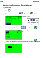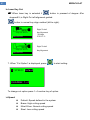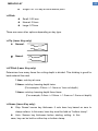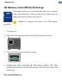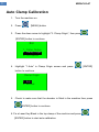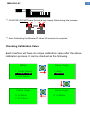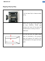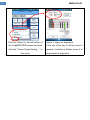
1
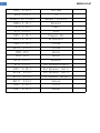
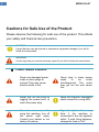
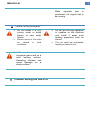
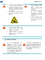
Preface: Miracle A7 key cutting machine works better and more convenient with LISHI 2-in-1 Auto Pick & Decoder. A7 is able to program 90% keys directly when all keys lost without removing chip, just 10 minutes’ work. LISHI Auto Pick Table: No. HU100 2-IN-1 Applicable Models Opel, Buick HU64 2-IN-1 Mercedes Renault 2-in-1 Renault VA2T 2-in-1 Triumph HU101(10) 2-IN-1 Focus SIP22 2-IN-1 Fiat TOY40 2-IN-1 Old Lexus TOY48 2-IN-1 New Lexus NE78 2-IN-1 Peugeot 406 Toyota2 2-in-1 HU58 2-IN-1 HU83 2-IN-1 HU100R 2-IN-1 New Toyota 2 Track Old BMW Peugeot 307 2010 BMW YM30 2-IN-1 Old Saab NE66 2-IN-1 Volvo HU43 2-IN-1 Old Opel HU56 2-IN-1 Old Volvo CH1EPICA 2-IN-1 EPICA Price 1 MIRACLE-A7 HU92 2-IN-1 New BMW HU66 2-IN-1 VW Renault(A) 2-in-1 Renault Mirrors HON66 2-IN-1 Hyundai TOY43 2-IN-1 Camry GT15 2-IN-1 Fiat NE72 2-IN-1 Peugeot 206 MIT11 2-IN-1 Mitsubishi NSN14 2-IN-1 Nissan NSN11 Nissan 2-IN-1 YM28 2IN1 Buick HU46 2IN1 Buick HY22 2-IN-1 Hyundai HY16 2-IN-1 New Hyundai(Right) HY15 2-IN-1 Old Hyundai (Left) HYN7R 2-IN-1 Old Hyundai (Left) HYN11 2-IN-1 Old Hyundai (Right) DAT17 2-IN-1 Subaru HU49 2-IN-1 Jetta HU87 2-IN-1 Suzuki 2 MIRACLE-A7 CONTENTS Cautions 4 Cautions Cautions for Safe Use of the Product Check List for Errorless Use Of Machine 8 Please Complete the Following Process Prior to 10 First Use MIRACLE-A7 Introduction 13 MIRACLE-A7 Parts 14 MIRACLE-A7 Part Naming 16 MIRACLE-A7 Specification 17 Key Alignment 18 Clamp Stop Clamp Stop Numbering Top and Bottom Clamp Stopper Normal Key Alignment (Left-to-Right) Right-to-Left Key Alignment Key Pad 23 Menu Structure 25 Menu Key Cutting Decoding 3 MIRACLE-A7 28 Cutter Replacement Tool Replacement Using a Cutter with Different Diameter Spindle Belt Change 30 Key Error Measurement Method 31 Key Cutting Sequence (Stand-Alone) 32 Decoding Sequence (Stand-Alone) 37 SD Memory Card Exchange 39 Saving Key Profile into SD-Memory (EB-24) 41 Program Installation 42 Key Cutting Sequence (Using PDA) 45 Pocket CodeMASTER Details 51 Bluetooth Communication Setting 57 Auto Clamp Calibration 60 Y- axis Origin Alignment Method 62 Making New Key Profile 67 Accessories 72 Ford(Tibbe)clamp LDV(FO19) clamp Auxiliary Clamp (AC-04) 4 MIRACLE-A7 Cautions MIRACLE-A7 & its application software is a system developed for skilled car key makers. The manufacturers or their agents are not responsible for any use for illegal purposes. Never blow away the chips [swarf] left after key cutting. The blown chips may damage the electronic parts. Inactivity will set the PDA in suspend mode with its screen turned off for battery power saving. Press the PDA power switch if you want the screen turned on and wait about 10 seconds until the "Bluetooth" to be connected. Press the "Start Transmission" button at least 10 seconds after you have pressed power switch or the machine may cause communication errors Notice Please use the correct key blank for precision key cutting. The Miracle A7 will not automatically correct your error in key blank selection. This equipment is not suitable for every car key cutting. In case of doubt ask your dealer for technical help. 5 MIRACLE-A7 Cautions for Safe Use of the Product Please observe the following for safe use of the product. This affects your safety and financial loss prevention. CAUTION A sign that you may get injured or experience equipment damage if you fail to follow the instructions WARNING It’s the sign that you can be seriously injured if you fail to follow the instructions Power related cautions Never use damaged power cords or loose plugs or sockets They may cause electric shock or fire Never plug in many cords in an simultaneously. The may get too hot and fire. power outlet outlet cause Never pull out the plug by tugging the power-cord, or touch the power plug. Keep the machine unplugged when unused for a long time. If smoke rises up while using the machine, turn off the power right away. Contact your dealer or our factory for advice. Cigarette lighter fuse may blow if the machine is connected to the car cigarette outlet. If such thing happens, change the fuse to 15A. 6 MIRACLE-A7 While cigarette jack is connected, car engine has to be running. Caution during installation Do not install it in oily, smoky, moist or dusty places or new water basins Electric shock or fire could be caused in such conditions. Install the machine on a level horizontal plane and on a solid working surface. Operating vibration can cause damage on a shaky surface. Caution during the use of it Do not put burning cigarettes or candles on the machine and install it away such heating apparatus such as stoves. The unit could get overheated, resulting in failure or fire. 7 MIRACLE-A7 The blade of the machine spins at high speed during its operation. Be careful not to put any part of worker’s body or clothing or other things inside of the machine. The operator may get seriously injured by the cutter if this is ignored. Do not put any tools, water containers, mugs, cups or small metal pieces on the unit or cutting bed. Vibration of the machine or the worker’s carelessness can cause these things to enter the machinery If the unit gets wet, electric shock and fire can be caused. Switch off at once. Be careful not to catch any part of your body or clothing in the route of each axis of the machine so as not to be scratched by its blade. Serious injury or machine damage can be caused by careless actions. Other cautions Do not disassemble or remodel the body of the –fire, machine electric shock& equipment failure can be caused. If you need a check-up, adjustment, repair of the machine, please ask your dealer for service or contact our factory Curiosity or carelessness of the young children about the machine may lead them to touch the machine and be hurt. Keep them away from the machine MIRACLE-A7 In winter, sub-zero temperatures, may cause the unit to be unable to work properly. If such thing happens, increase the temperature of the work environment. Do not let the machine room temperature go below zero 8 9 MIRACLE-A7 Check List for Errorless Use of Machine This machine is designed to work at 12vDC. Therefore 12vDC needs to be supplied suitable to the polarity (+/-) for normal operation. If power other than the 12vDC is used, normal operation can’t be assured and damage of electronic parts may occur. This machine can use the power from car cigarette jack. If the carfuse blows change it for 15A, then retry. Some cigarette jack connect wires have a fuse inside them. If the machine doesn’t work using this then check the fuse in the connector wire. Keep the car engine turned on while using the apparatus connected to the car cigarette outlet. Voltage from cigarette jack for some cars is 24V. If the machine gets power from the cigarette jack of such cars, its electronic parts will be damaged so you need to use a converter to change 24V into 12vDC. Check the condition of cutter periodically. A lowering of cutting ability from a seriously worn cutter will prevent precise key cutting. Use the correct setting – Brass or Steel Key. Change the spindle belt periodically. If change intervals are missed, cutter can break up or drop its cutting ability, resulting in failure in precision key cutting. MIRACLE-A7 The alloy of the key cutting material affects the cutting ability of cutters. If the materials are strong with low cutting ability, work adjusting the cutting unit & speed as slow as possible. The A7 has settings for Brass and Steel. Activation of this machine near Bluetooth wireless communication can cause malfunction of the machine by radio wave interference. If such thing happens, turn off the power and then restart. Be careful not to drop the machine or get it wet by rain or snow when being used or carried outdoors. Always double check you are using the correct key blank as defective keys will be made no matter how correctly the unit may cut. Never blow away the chips left after the key cutting. The blowchips can get inside the machine and damage the electronic parts. 10 11 MIRACLE-A7 Please Complete the Following Process Prior to First Use 1. Assemble handles (AC-12) for Shield Cover and Tray. 2.If the product is installed inside vehicle, fix it firmly using mounting bracket (AC-06). MIRACLE-A7 3. Calibrate Clamp - To ensure errorless cutting of a key, clamp should be calibrated prior to first use 1. Turn MIRACLE-A7 machine on, by twisting the red knob in a clockwise direction. 2. Press the “MENU” button and press the down arrow to highlight “2. Clamp Origin Set”, then press the “ENTER” button to continue. 3. Highlight “1. Auto” in the “Clamp Origin Set” screen then press “ENTER” to 12 13 MIRACLE-A7 continue. MIRACLE-A7 4. Check to make sure that the decoding probe is fitted in the machine then press “ENTER” button to continue. 5. Fix a Laser key blank in the top clamp of the machine then press “ENTER” to start Auto-Calibration. Auto-Calibration will now commence. Now, the machine is ready to cut keys. 14 15 MIRACLE-A7 MIRACLE-A7 Introduction - ALL-IN-ONE Electronic Automobile Key Cutting Machine Miracle-A7, All-In-One, Edge & Laser Key Cutting Machine is an innovative solution dedicated to locksmiths. It is an electronic three axes key cutting machine which operates with state-of-theart mobile devices like PDA, Smart Phone, UMPC etc. - Edge, Double Side & Laser Key Cutting in ONE SYSTEM - Bluetooth Wireless Communication - Stand-Alone - Decoding and Cutting - Full Automatic Electronic 3 Axes Key Cutting Machine - All Kind of Key Data are provided - Various Kind s Of Mobile Device Support like PDA, Smart Phone, UMPC, Laptop etc. - Very Compact & Light Weight for Easy Carry - Various Power Input (Portable Battery, Vehicle Cigarette Cord, AC etc.) - Cuts a Key same as the Original just in 2~3 minutes SUPPORTED AUTOMOBILE MAKERS: Acura, Alfa Romeo, Audi, BMW, Cadillac, Chrysler, Citroen, Daihatsu, Dodge, Ducati, Ferrari, Fiat, Ford, GM, Holden, Honda, Hyundai, Infiniti, IVECO, Kia, Lancia, Land Rover, Lexus, Lincoln, Mazda, Mercedes Benz, Mercury, Mini Cooper, Mitsubishi, Nissan, Open, Peugeot, Piaggio, Porsche, Proton, Renault, Rover, Saab, Skoda, Subaru, Suzuki, Toyota, Vauxhall, Volkswagen, Volvo etc. 16 MIRACLE-A7 MIRACLE-A7 Parts Following are the parts coming with the machine when you buy it Contents Cutter (TL-EM2.0) Decoder (TL-PB1.0) T-Wrench (AC-08) Fig Qty. Use Tools for key cutting 1 EA (Flat, 6mm Shank, 2mm Blade) 1 EA Tool for decoding 1 EA Tool change It transmits spindle motor power Spindle Belt to spindle. 3 EA (AC-08) diameter) Battery charging(12V/5A) AC Charger 1 EA (AC-01) Bolt (AC-09) Stopper (AC-03) (G40: 3mm thick, 40mm in (5.5mm x 2.1mm) 2 EA 1 EA Used to fasten cutter or decoder in the spindle Guide for alignment-key location 17 MIRACLE-A7 Stopper (Right-toLeft) Guide for alignment-key location 1 EA to fix a key from right-to-left. (AC-11) 12V power supply from car Car Cigarette Jack Cord cigarette jack 1 EA must be over 15A (AC-07) Instruction manual Instruction 1 EA ☞ manual “CodeMASTER” program CD Program CD *** Fuse for the cigarette jack 1 EA ( SW for car key cutting and update) Being spendable, cutter, battery and spindle belt need to be changed periodically. ☞ When cigarette jack cord is used as power source, the fuse of that jack MUST be over 15A. Consult automobile technician for replacing fuse. MIRACLE-A7 18 19 MIRACLE-A7 MIRACLE-A7 Part Naming Name of Each Part Front Shield Cover Key & LCD Power Switch (Emergency Switch) LED Light Clamp DC Motor Clamp Knob Spindle Chip Tray Cutter 20 MIRACLE-A7 MIRACLE-A7 Specification Power Input 14.4vDC / 2.5AH (5.5 x 2.1mm) Power Consumption 60W Dimension 245 (W)×270 (H)×295 (D)mm Weight 22kg Resolution XY Axis: 0.005mm, Z Axis: 0.0015mm Spindle Revolution 12,000 rpm Bluetooth Spec. Bluetooth Specification V1.2 Frequency 2.4GHz ISM Band Profile SPP, GAP Temperature 0 - 40 ºC Humidity 10 - 90 % Usage Automobile key cutting 21 MIRACLE-A7 Key Alignment MIRACLE-A7 is a key cutting machine available for various types of edge, double side and laser keys, which accompanies clamp and stopper capable of fixing many sorts of keys quickly and easily. Following are the key fixing method by type Following are the alignment explanations: Clamp Stop Clamp has all 5 stops for key align. Before cutting a key, proper stop position must be selected for correct alignment depending on the type of each key. Clamp Stop Numbering Each stop is numbered from 1 to 5 as shown in the below figure. #1 #2 #3 #4 #5 Usually, #1 stop is used for shoulder-aligned key while #2, 3, 4 and 5 for tip aligned key. Key length will determine which stop to be used among #2, 3, 4 and 5. You choose this stop number when choosing clamp stop while cutting process in LCD or Mobile devices like PDA. #4 stop is default stop for tip-aligned key. So when you chose to cut tip-aligned key, #4 is selected initially. Then you can change the stop depending on the key MIRACLE-A7 length. Sometimes, machine or S/W will automatically choose different stop automatically. 22 23 MIRACLE-A7 Top and Bottom Clamp: Key can be held on top or bottom of clamp depending on the type of key. Edge or double sided non laser keys are always held on top clamp. Laser key can be held on either, but using bottom clamp is recommended. Fixing a Key on Top Clamp: (Mostly Edge or Double-Sided Non Laser Keys) Fixing a Key on Bottom Clamp: (Mostly Laser Keys) Stopper (Stop Guide) Stopper shown in the left figure is used to align key correctly. Insert the stopper into proper groove. Then place a key making its shoulder or tip touch this stopper. [Shoulder Align] [Tip Align] 使用反向Use Right-to-Left Stopper Block to align laser key with short length. 24 MIRACLE-A7 [Tip Align for Right-to-Left] [Shoulder Align for Right-to-Left] 25 MIRACLE-A7 Normal Key Alignment (Left-to-Right) Shoulder-Aligned Key 1. Put stopper in the stop of Shoulder Align stop (#1) 2. Place the key shoulder to touch the stopper. Tighten up the clamp firmly and fix for the key not to move. Then remove the stopper. Tip-Aligned Key 1. Put stopper in the stop of Tip Align stop (#4) 2. Place the end of the key to touch the stopper. MIRACLE-A7 CAUTION ☞ Be careful not to fix a key incorrectly as the following figures when cutting or decoding. Standard(Edge) Key: Laser Key: 26 27 MIRACLE-A7 Right-to-Left Key Alignment (for Short Laser Key Only) A key which is not suitable for left-to-right alignment can be fixed from right to left direction. ☞ Not all key can be fixed this way. It’s for only laser key with SHORT length in which left-to-right alignment is not available. Normal laser keys may touch right wall while cutting due to its length. In this case, it SHOULD NOT be fixed in this way. Shoulder Align Key Place a key as shown in the above making its shoulder touch right end of clamp. 28 MIRACLE-A7 Tip Align Key 1. Put right-to-left stopper block as shown in the above. 2. Place the end of the key to touch the stopper. 29 MIRACLE-A7 Key Pad Menu: Selects menu item Input Number: Inputs bitting number Inputting number 1~5: - Press the button. Inputting number 6~0: - Press the button again when 1~5 is displayed. Menu: Moves back Input Bitting: Inputs decimal Menu: : Moves to previous/next 30 MIRACLE-A7 menu page : Moves menu item selection Input Number: : Moves to next input position : Increase/Decrease number Load key data by pre-defined shortcut code. [Load key by Shortcut-Code] Load key data from maker list. [Retrieve key by Maker] [ENTER] [MENU] Confirms selection or starts action. Goes into menu Measures cutter or decoder length [TOOL CHANGE] While cutting: Cancel cutting [STOP] Menu: Jump to start 31 MIRACLE-A7 Menu Structure Menu: [Menu] 1. Cutter Option 2. Clamp Origin Set 3. Cut Option Cutter Option Diameter: 2.0 mm Clamp Origin Set Cut Option 1. Auto 2. Manual Manual Origin Set 1.Cut Speed X: 4.05 mm Y: 15.00 mm 1. Slow 2. Normal 3. Fast Clamp Origin Set 2.Pitch 1. Auto 2. Manual 1. Small 2. Normal 3. Large 3.Nose Length Length: 2.0 mm 5.Clamp Touch 1.Yes,Warn 2.No 4.Z Pitch 1. 1 time 2. 2 times 3. 3 times 32 MIRACLE-A7 Key Cutting: [ACURA] [ALFA ROM.EO] [APRILIA] [AUDI] [BMW] BW7 BW8. HU50 HU58 HU92 1/10 Select Job 1. Cut 2. Decode 3. Info 1: SPEED: Default 12345678 AB 2 4 1 _ _ _ _ _ _ 1 4 Align as above. CHANGE: 1~4 Next=ENTER ☞ By pressing key “5” ☞ By pressing button at in this stage, cut depth can be adjusted when laser key is selected. stopper #1 or #5 position, key align direction can be changed to right-to-left. Input Cut Depth Depth: 1.0mm Align as above Next=ENTER Align as above Next=ENTER Right-To-Left Key Alignment :Tip Align Right-To-Left Key Alignment :Shoulder Align 33 MIRACLE-A7 Decoding: Select Job Probe Change 1. Cut Please, replace 2. Decode tool to probe 3. Info Start=ENTER Decoded: 12345678 AB:23141231 Decoding... No. Read: 23141231 NO:23_ _ _ _ _ Bitting Analysis 1. Direct Copy 2. Nearest Align as above. Next=ENTER Measuring key surface. Please wait... 34 MIRACLE-A7 Cutter Replacement Cutter is expendable so requires periodical replacement to avoid leaving burrs on the key or even breaking a key be. If the cut surface of the key is not slick or has burrs on it, or the key fixed to the clamp is bent by the cutter, the cutter has to be replaced. Type Flat Endmill Shank Diameter 6 mm Blade Diameter 1.0~2.4mm 2.0mm is recommended. The key point of cutter replacement is as below Tool Replacement Cutter is replaced through 2 steps, starting to press the [TOOL CHANGE] in the keypad button and then carry out each step one by one. 1. Release cutter tightened bolt with the 2.5mm wrench and then pull out the cutter downward. Then put in a new cutter, seat it correctly then tighten the bolt. 2. Press the [TOOL CHANGE] button in the keypad to measure the cutter length. It will move to clamp center and goes down to touch cutter tip to 35 MIRACLE-A7 know its length. Once it is sensed, it will return to home position ending the measurement Using a Cutter with Different Diameter : Stand-Alone [Menu] 1. Cutter Option 2. Clamp Origin Set 3. Cut Option : Mobile Device (PDA) Cutter Option Are you sure to save change? Diameter: 2.0 mm Save=ENTER 36 MIRACLE-A7 Spindle Belt Change The spindle belt is a part transmitting the turning force of the spindle motor to the spindle for the cutter to turn, and the abrasion of the spindle belt can cause its surface to be cracked or slippery so stopping the spindle motor’s turning force from transmitting to the spindle, resulting in lowering the number of rotation of cutter, lowering the cutting quality of the key, and even causes the breaking up of cutter. Type G40 Silicon Belt Thickness 3mm Diameter(Inside) 35mm Change intervals The life of the spindle belt varies to the condition how they have been used, but the average change intervals are every 6 month. Spindle belt change 1. Unbolt the 5 cover fastening bolts. 2. Open cover. 3. Replace the belt to new one and close the cover. 37 MIRACLE-A7 MIRACLE-A7 Key Error Measurement Method Correct materials are necessary for making a precision key Following are the explanation for selecting the materials for making a precision key Measure the length of both sides of a key with calipers as seen in Fig If the error of the length of Side A and B exceeds 0.1mm, it shouldn’t be used if possible, but if it is inevitable to use it, you have to expect unsatisfactory results. 38 39 MIRACLE-A7 Key Cutting Sequence (Stand-Alone) Ex)BMW->BW7 1. Press button to list automobile maker. 2. Select proper maker pressing into its key list. [ACURA] [ALFA ROM.EO] [APRILIA] [AUDI] [BMW] 1/16 button to move Page ☞ 1/10 button. Then press Select Job 1. Cut 2. Decode 3. Info button Page 4. “Select Job” pane will be shown. Select job to do then press to start. will show you previous or next page. 3. Select key model in the list pressing to select it. BW7 BW8. HU50 HU58 HU92 . Then press button 40 MIRACLE-A7 Cut: Cut a key with bitting number input. Decode: Read bitting of key then show it for duplication. Info: Shows key basic information 5. Input bitting numbers. Once input every numbers, press step. to move to next 12345678 AB 2 4 1 _ _ _ _ _ _ 1 4 AB: means Side A and B has same bittings. .:means decimal digit of bitting. Pressing input mode. 1-4: means it has bitting number from 1 to 4 will go into decimal 6. Fix a key aligning to the stop guided on the LCD screen. Then press to move to next step. Align as above. Next=ENTER ☞ If it is tip-aligned key, you can move the stop by pressing depending on the key length. button 41 MIRACLE-A7 In Laser Key Cut: ☞ When laser key is selected if button is pressed of stopper #1or stopper# 5, is Right-To-Left alignment guided. button to normal key align method (left-to-right). Align as above Next=ENTER Right-To-Left Key Alignment :Tip Align 钥匙尾定位 Right-To-Left Align as above Key Alignment Next=ENTER 7. When “Cut Option” is displayed, press to start cutting. 1: SPEED: Default CHANGE: 1~4 To change cut option press 1~4 number key of option. >>Speed: Default: Speed defined in the system Brass: High cutting speed Nikel-Silver: Normal cutting speed Steel: Low cutting speed 42 MIRACLE-A7 Single Cut: Cut key at once without pitch Small: 0.25 mm Normal: 0.5mm Large: 0.75mm >>Pitch: There are some other options depending on key type. >>Tip (Laser Key only): Normal: Nosed: >>Z Pitch (Laser Key only): Determines how many times the cutting depth is divided. This dividing is good for hard material like steel. 1 time: cuts key at once 2 times: cuts key lowering depth twice. (For example, 0.5mm -> 1.0mm on 1mm cut depth) 3 times: cuts key lowering depth three times. (For example, 0.4mm -> 0.8mm -> 1.2mm on 1.2mm cut depth) >>Sense (Laser Key only): Skip: Doesn’t sense key thickness. It cuts laser key based on zero to clamp surface. In this case, laser key must be held on “bottom clamp”. Auto: Senses key thickness before starting cutting. In this case, key can be hold on either top or bottom clamp. 43 MIRACLE-A7 ☞ By pressing key “5” in this stage, cut depth is adjusted (Only when laser key is selected). Input Cut Depth Depth: 1.0mm 44 MIRACLE-A7 Decoding Sequence (Stand-Alone) When decoding, a special tool, the “Decoder” is used. ☞Only a key that is conductive electrically can be decoded. If not, decoder will be broken 1. Select a key as the procedure of key cutting. 2. When job selection is asked, select “Decode”. Select Job 1. Cut 2. Decode 3. Info 3. Replace tool to decoder, 4. Place a source key on the clamp aligning it as key cutting. 5. Press to move to start decoding. 6. After decoder measures key height, it will read bittings displaying read number. Decoding... No. Read: 12 NO:23_ _ _ _ _ 45 MIRACLE-A7 7. Once it has read all biting, it will show you the all biting read. Decoded: 12345678 AB:23141231 Cut=ENTER If you want to cut new key with this bittings (duplicating), press . 8. Bitting number translation will be asked as in the below. Bitting Analysis 1. Direct Copy 2. Nearest Direct Copy: Cuts key just as read. It doesn’t convert the most matching code. Nearest: Cuts key converting the read number to nearest by rounding. For example, 1.7 -> 2, 3.2 -> 3 etc. It can calibrate sensing error. Decoder is very easy to break. Handle with special care. Especially avoid dropping, impacting or abnormal use while decoding by user Decoder doesn't bend but breaks. Bent decoder can produce severe decoding error. So, breaking, not bending was intended. User is responsible for broken decoder at any case. 46 MIRACLE-A7 SD Memory Card (EB-24) Exchange SD memory card stores all key profile data used to cut or decode when used stand-alone. New key data can be added easily by adding data files into memory card from PC. MIRACLE-A7 supports SD memory up to 2GB capacity non-SDHC 1. Turn power off 2. Take off the clear plastic cover by unbolting 2 bolts using screw driver. 3. Pull out the SD memory card with your finger. 4. Upgrade key data connecting the SD memory card to PC. Then, reinstall SD memory card into SD memory card slot in the back, then close cover. Formatting SD Memory 47 MIRACLE-A7 MIRACLE-A7 supports FAT file system and SD memory was formatted with that format. If unformatted SD memory or the one with different file system is used, it should be formatted by FAT file system. Please refer to the figure in the below. Right Mouse Click MIRACLE-A7 Saving Key Profile into SD-Memory (EB-24) 1. Remove the SD card from the back of the machine and insert it into computer SD memory slot or USB SD memory reader 2. Select a key profile and press “Save to SD Memory” button. 3. Designate destination directory in SD memory, then press “Save” button. 48 49 MIRACLE-A7 Program installation Preparations: Prior to program installation for mobile device like PDA, it has to be connected to PC, notebook et al with sync cable. The PC or notebook should have program superior to ActiveSync 4.5. (*Windows Vista, 7 or above supports Windows Mobile Device Center instead of ActiveSync) [ActiveSync 4.5] Once the software which came with the MIRACLE-A7 is installed, window for CodeMASTER will appear as below. You can cut keys, install s/w to PDA, copy data to SD memory and maintain data to the latest in the s/w. Whenever the s/w runs, it checks update automatically. Once update exists, it 50 MIRACLE-A7 informs the update as in the below and enables update buttons for mobile device like PDA and SD memory. Update Notification Button for Update Shows key profiles and cuts key. Manages customer information Shows video instruction Install s/w to PDA erasing all previous s/w and data. (*CAUTION: This will erase all key profiles including user-made data in the PDA) Erases all data in SD memory, then copy the newest key profile to it. (*CAUTION: This will erase all key profiles in SD Memory) Update s/w and key profiles to the latest to PDA. (*This will keep all user-made profiles) Update key profiles to the latest to SD memory (*This will keep all user-made profiles) 51 MIRACLE-A7 52 MIRACLE-A7 PDA S/W Installation Click or button 1. Select correct destination 2. Click this button to start SD Memory Update Click or button 1. Select correct destination 2. Click this button to start 53 MIRACLE-A7 Key Cutting Sequence (Using PDA) “ CodeMASTER” is the SW for car key cutting offering various convenient functions for all types of car key data & key cutting easily and quickly. CodeMASTER functions both for PC and for PDA, the screen configurations of which are almost identical although OS are different. Especially the S/W for PDA is named as “Pocket CodeMASTER(PCM5)”. Minimum Requirement: - Pocket CodeMASTER[PCM5] (for PDA) OS: Windows Mobile 5.0 or later Hardware: Storage over 10MB, Bluetooth The explanation below is based on “Pocket CodeMASTER(PCM5)” for PDA, but its contents are almost similar to that for PC. Key Cutting Sequence using PCM5 in PDA 54 MIRACLE-A7 1)Turn on the PDA and run the “PCM5” in “Start” If it’s not in “Start”, search it in “Programs” and then run 2) Tab the “Automobile Key Cut” button 3) If CodeMASTER starts to run, a screen as seen in the Fig appears. Find the wanted maker and then tab it. 4) Select the car type of the key to make and then tab “Input Bitting...” 55 MIRACLE-A7 5) Input the bitting number using number keypad The screen after the bitting number input ☞ The number seen in the window for biting number input is up to the profundity phase number of the selected car type. In other word, the car with 4 cut depths is marked as 1-4, 5 depths as 1-5, 9 depths as 1-9 to prevent input mistake of by operators. It also functions to detect the depth cuts of the selected car model. Tab here to switch screen 56 MIRACLE-A7 6)Tab the “Start Key Cutting” button 7) Options (cutter diameter, pitch, and engraving speed) and clamp origin position that need for key fixing are suggested. Check up and if nothing is wrong, fix the key of the selected car to machine clamp firmly adjusting it to the chosen clamp origin and the tab “OK” button. [Shoulder-Align Key Holding] [Tip-Align Key Holding] 57 MIRACLE-A7 In Laser key cutting, it could be fixed to the bottom of the clamp Click the “Bottom” in the clamp menu seen in the left screen, fix the key on the bottom clamp seen in Fig in the below. 58 MIRACLE-A7 8) The key to be made appears on the screen. Machine makes a key following the pattern, and you need to check up if the key on the screen is what you wanted, and it is, tab the “Transmit” button *** Inactivity will set the PDA in suspend mode with its screen turned off for battery power saving. Press the PDA power switch if you want the screen turned on and wait about 10 seconds until the "Bluetooth" to be connected. Press the "Start Transmission" button at least 10 seconds after you have pressed power switch or the machine may cause communication errors 9) Data is transmitted to the engraving machine, and the making of the key with the Pin number input starts. 59 MIRACLE-A7 60 MIRACLE-A7 Pocket CodeMASTER Details Model List Screen Model list Key DB classified into car model & maker Summarized Brief key information by key information selected car type Bitting number Button for movement to the input window for bitting number input Menu Menu for various setting like clamp origin setting, communication port, product selection etc. Short Cut Tab here to show makers with certain range of initial only. Bitting Input Screen Bitting Input The window where you can see the bitting number input Bitting Adjust It’s the button enabling the users to input point unit bitting number like 1.5, 2.7 etc. 61 MIRACLE-A7 Preview It’s the button enabling the users to simulate key shape with the input bittings Save It’s the button enabling the users to register key cutting information with the selected car type and bitting number Start Key Cutting t’s the button for starting key cutting process Reset It’s the button to delete all the bitting numbers. Preview Screen Simulate key shape of input. Tab this screen to switch to input screen Input It’s the button enabling the user to switch to the window with the bittings input. Note It’s the button to show the explanation for the selected car type, if any. (This button shows the window only for the case explanation or Figs are 62 MIRACLE-A7 registered for the selected key types) New Key It’s the button enabling the users to return to key list showing window for selecting new key type <-, -> These buttons move cursor (blinking black vertical bar) position of bitting number to the left or right. Number keypad It’s the button for inputting bitting number. It functions up to the profundity phase number of the selected key. In other word, the key with the profundity of 4 phases marks as 1-4, 5 phases as 1-5, 9 phases as 1-9 to prevent users from inputting invalid number. It also functions for the users to detect the profundity phases number of selected key type 63 MIRACLE-A7 Code Adjustment Screen Change When the arrow button is pressed All for the checkup of this item, bitting number in every space goes up or down by 0.1. If this item hasn’t been checked up, the pin number in the space on which cursor blinks, changes. 0.5 If checked up, the bitting number changes by 0.5 when press button, if not checked up, the bitting number changes by 0.1. Cut Option Selection Cutter Input the diameter of the cutter presently used for key cutting. The precise size of the cutter should be input, otherwise, the key cut will be incorrect. Pitch Set up key cutting unit which means 64 MIRACLE-A7 by what mm interval of cutting should be determined, with a greater unit that brings about a noise a little louder, but cutting time shorter, or a smaller unit that lowers down noise but prolongs cutting time. Speed Designate the cutting speed (but not cutter rotating speed) in the key cutting process. Designates at high speed for brass material, at average speed for nickel material. Depth (Only for Laser key) Designates the depth of key cutting Z Pitch (Only for Laser key) If a key is to be made with the depth above, the depth can be divided as much times as designated numbers. Then decide how much time to be divided for the production if the depth is decided as 1mm and depth division as 2 times, the key is made with 0.5mm at first, and then 1mm at second time. This principles is based on the fact the making of Laser key of 65 MIRACLE-A7 such a hard material like nickel with its depth deeper than 1mm, it protects cutter if designated more than 2 times of processing along with cutting down noise, and a key of very accurate size can be made. But the increased time requires increased processing. Top/Bottom (Only for Laser key) Designate which clamp to choose in the top or bottom for key alignment. All bit keys are chose to the Top by all means fixed to the top clamp. Laser key is flexible in choosing top or bottom clamp, but bottom is chosen in general. Example of clamp use: Example of top clamp use: Example of bottom clamp use: MIRACLE-A7 66 67 MIRACLE-A7 Bluetooth Communication Setting COM port is a gate that the data is transmitted through. Once Bluetooth connection is established, the proper COM port must be selected. Specific COM port is variable depending on operating system and PDA. But the most PDA is connected through COM6 and rarely COM8 and some others. COM Port Selection PDA HP COM6 (Select COM8 or other if COM6 is not available) ☞ *** Inactivity will set the PDA in suspend mode with its screen turned off for battery power saving. Press the PDA power switch if you want the screen turned on and wait about 10 seconds until the "Bluetooth" to be connected. Press the "Start Transmission" button at least 10 seconds after you have pressed power switch or the machine may cause communication errors. Bluetooth Connection 68 MIRACLE-A7 Click“A5” or “MIRACLE-A5” icon 69 MIRACLE-A7 Connect icon is created Tab this icon for 1 second. Tab the icon for 1 second Make sure that Tab the icon for 1 second until you see pop-up menu “Authentification” is again then tab “Connect” to then tab “Properties” checked. connect “Connect” Bluetooth Connection is established now 70 MIRACLE-A7 A pop-up window will request “PIN-Code”. Input 4 zeros (“0000”) then tab “OK” on the bottom. HP PDA: COM6 (if COM6 is not available, select COM8 or other instead) 71 MIRACLE-A7 Auto Clamp Calibration 1. Turn the machine on. 2. Press [MENU] button 3. Press the down arrow to highlight “2. Clamp Origin”, then press [ENTER] button to continue. 菜单 1. Cutter Option 2. Clamp Origin 3. Cut Option 4. Highlight “1.Auto” in Clamp Origin screen and press [ENTER] button to continue. Clamp Origin 1. Auto 2. Manual 5. Check to make sure that the decoder is fitted in the machine then press [ENTER] button to continue. 6. Fix a Laser Key Blank in the top clamp of the machine and press [ENTER] button to start auto-calibration. 72 MIRACLE-A7 *** CAUTION: DO NOT have the extra key clamps fitted during this process. *** Auto-Calibrating the Miracle A7 takes 20 seconds to complete. Checking Calibration Value Each machine will have its unique calibration value after the above calibration process. It can be checked as the following. MENU 1. Cutter Option 2. Clamp Origin 3. Cut Option Clamp Origin X: 5.43mm Y: 32.24mm Clamp Origin 1. Auto 2. Manual Clamp Origin X: 5.43mm 73 MIRACLE-A7 Y- axis Origin Calibration Method All keys are cut with origin to center of key in all “Miracle” key cutting machines. So the center of the key (the center of clamp (y-axis)) is set to the origin as seen in Fig below, and so precise set up of the center point, that is the center of Y-axis of the clamp is very important. If the midpoint value of Y-axis hasn’t been set up properly, key is cut being inclined to one side, which needs to be corrected by aligning the origin of Y-axis. ☞This step will not be needed in normal case because miracle-A7 calibrates automatically. The following explanation was given just for conceptual understanding on the calibration. Clamp Y axis centerline 74 MIRACLE-A7 Aligning Step by Step Fix the Laser Key to clamp as seen in Fig. Select the key type of the fixed one (in here, LEXUS’s TOY40 was chosen) and input all the same the numbers seen in the Fig. (In here, 4 was input) Cut the key with the same bitting input as described in the previous step and measure the length of the remained parts in the upper and lower parts. 75 MIRACLE-A7 Click the “Menu” in the left bottom of Adjust Y origin for alignment. the CodeMASTER screen and then If the top of the key is thicker move it click the “Clamp Origin Setting…” in upward, if bottom is thicker, move it to the menu downward for alignment. 76 MIRACLE-A7 2.2mm (2.2mm-1.2mm) ÷ 2 1.2mm Example-1: If a key was made as seen in Fig, move to the thicker side (it is upward direction in the above case) as much as half of the error thickness, that is, ( top 2.2mm – bottom 1.2mm ) = 1.0mm, So half of the difference is 0.5mm (1.0mm / 2 = 0.5mm). 1.2mm (2.2mm-1.2mm) ÷ 2 2.2mm Example-2: If a key was made as seen in Fig, move to the thicker side that is downward as much as half of the error thickness. So (bottom2. 2mm – top1.2mm ) = 1.0mm, and (move downward as much as1.0mm / 2) = 0.5mm 77 MIRACLE-A7 Input Y origin and click the “Save” button for turning back to initial CodeMASTER screen, and Y origin alignment is over 78 MIRACLE-A7 Making New Key Profile: - This guide will explain new key profile creation from PC software mainly but it’s applied exactly same in PDA software (Pocket CodeMASTER, PCM5). Run the “CodeMaster” in PC (or “Pocket CodeMaster” or “PCM5” in PDA). Now run “Instacode” and select the key blank you want. For this exercise we will be using TOY43 8 cut. We are going to need the spacing, depth, width of key and the biting width. 1. Scroll down to the manufacturer and for the PDA you will need to use the stylus and hold down for a second or so and for the PC software, use the mouse and right click. [ PC ] 2. [ PDA ] When you right click the mouse you will get a new sub menu. Go to “Add new key profile”. 79 MIRACLE-A7 3. Choose the correct keyway. Now go to Step 2. Choose the spaces and the alignment and whether side A and B are the same and also Pin Width. Using Instacode, get all the information from there. In this case there are 8 spaces, it is Tip stop and the Width is 100. Now enter the first space which is 2240. Then go to space number 2 and you will get a dialog box. Enter the spacing between each cut. In this exercise it is 230. And press OK. This will fill in automatically. MIRACLE-A7 4. Now go to Step 3 and do the same. The depths, measurement and the key blade height. 一And this is what you should have. 80 81 MIRACLE-A7 5. Now go to Step 4 and fill in the key blank thickness and the distance to the tip as shown in the picture using a vernier. 6. Then go to Step 5 and fill in the lock biting from each lock as you would know it. If you are not sure then this can be left blank. MIRACLE-A7 7. You are now just about finished. Enter information like we have done here and save this new biting card. This is what you should now have after saving your information. If the new profile should be moved to SD memory also, refer to “ Saving Key Profile into SDMemory” section. 82 83 MIRACLE-A7 Accessories Tibbe Clamp (AC-17) Tibbe clamp enables both Ford and Jaguar key cutting with MIRACLE-A7. ☞ Tibbe clamp is optional part. It’s not included in the product package. How to Use: Loosen screw at Jaguar side and fasten screw at Ford. Not all the way through, until you feel the ball bearing engage. Repeat the opposite for Jaguar 8 cut. [Front View] Screw for Ford Screw for Jaguar Jaguar 8 Cut Side [Top View] Ford 6 Cut Side 84 MIRACLE-A7 Place the clamp on the main clamp and align at stopper #3 as in the below. Follow guide on the LCD in stand-along use or program in cutting by PDA or computer. 85 MIRACLE-A7 LDV(FO19) Clamp (AC-18) LDV(FO19) clamp enables LDV key cutting with MIRACLE-A7. ☞ LDV(FO19) clamp is optional part. It’s not included in the product package. Place the clamp on the main clamp and align at stopper #3 as in the below. Follow guide on the LCD in stand-alone use or the program in cutting by PDA or computer. 86 MIRACLE-A7 Auxiliary Clamp (AC-04) Auxiliary clamp enables easy SX9 key (Side A) and thin standard(edge) key holding. ☞LDV(FO19) clamp is optional part. SX9 Key Hodling Thin Standard(Edge) Key Holding 87 MIRACLE-A7