1
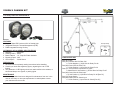
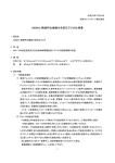
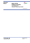
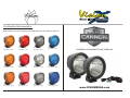
Global Lighting
Lighting Systems
Systems
Global
visionxusa.com
You May Also Be Interested In:
Beam Pattern and Color Changing Poly Carbonate Lens’ to Create 12 Lights in 1
PCV-CP1Y
Spot Pattern - Amber
PCV-CP1R
Spot Pattern - Red
PCV-CP1
Spot Pattern - Clear
PCV-CP1B
Spot Pattern - Blue
PCV-CP1YEU
Euro Pattern - Amber
PCV-CP1REU
Euro Pattern - Red
PCV-CP1EU
Euro Pattern - Clear
PCV-CP1BEU
Euro Pattern - Blue
PCV-CP1YFL
Flood Pattern - Amber
PCV-CP1RFL
Flood Pattern - Red
PCV-CP1FL
Flood Pattern - Clear
PCV-CP1BFL
Flood Pattern - Blue
Installation Intructions & User’s Manual
www.VISIONXUSA.com
VISION X CANNON KIT
Global Lighting
Lighting Systems
Systems
Global
visionxusa.com
You May Also Be Interested In:
(W1)
(R1)
(W2)
(+)
(-)
(W3)
FEATURES
1. Single 25 Watt LED Produces 1000’ of Usable Light
2. Integrated Electronic Thermal Management (ETM)
3. PWM Integrated Dimming Circuitry
OPTIMUS XIL-OP100 SERIES SPECIFICATIONS
1. Warranty
: Extended
2. Housing Colors : Black
3. Beam Patterns : 10°, Snap-On Filters Available
4. Mounting Depth : 2.80”
5. LED Lifespan : 50,000 Hours
PREPARATION
1. We recommend completely reading instructions before installing.
2. Consult your local state regulatory agency regarding the use of LED
lighting.
3. The placement of LED lighting should not restrict airflow to the radiator, or
block head lamps, turn signals, or parking lights.
MAINTENANCE
1. All Vision X models have been designed for maintenance free use. In the
case an LED lamp or other part replacement is needed please contact
your authorized service center.
(C1)
(S1)
(C2)
Example Relay
87
(W4)
89
86 Not Used
30
COMPONENTS KEY
Part (R1) Relay
Part (W1) Ground Wire for Relay Coil
a. 12 Volt Negative (-) Input Wire for Relay Pin 86
Part (W2) Power Wire for Relay Coil
a. 12 Volt Positive (+) Input Wire for Relay Pin 30
Parts (C1 & C2) Deutsch Connectors for Lights
a. Attached to12 Volt Positive (+) Power Wires for Relay Pin 87
Part (W3) Power Wire for Relay Input
a.12 Volt Positive (+) Input Wire for Relay Pin 85 [Part R1]
Part (S1) Toggle Switch
Part (W4) Power Wire for Switch Input
a. 12 Volt Positive (+) Input Wire for Switch [Part S1]
85
VISION X CANNON KIT
WIRING INSTALLATION
1. Find a suitable place to mount Relay [Part R1] leaving enough room for
Power & Ground Wire [Parts W1 & W2] to reach the Battery & the Deutsch
Connector Wiring [Parts C1 & C2] to reach the Lights. Mount Relay.
2. Run Power Wire [Part W1] & Ground Wire [Part W2] to the Battery. Connect
the Power Wire [Part W1] to the Positive (+) Battery Terminal & connect the
Ground Wire [Part W2] to the Negative (-) Battery Terminal.
3. Run the Deutsch Connector Wiring [Parts C1 & C2] to each Light and Plug
in. It doesn’t matter which Deutsch Connector plugs into which Light.
4. Unplug Power Wire [Part W3(+)] from the Toggle Switch [Part S1]. Run
Power Wire [Part W3(+)] to the Vehicles Fire Wall at the point that you will
bring the Wire through to the inside of the Cab (using a Factory Rubber or
Plastic Grommet is suggested). Run Power Wire [Part W3(+)] to the inside of
the Cab. Note: This Wire can be extended if necessary.
5. Find a suitable place to Drill the Hole needed to mount the Toggle Switch
[Part S1] and Continue to run the Power Wire [Part W3(+)] to that location.
Plug the Power Wire [Part W3(+)] into Outside Pin of Toggle Switch [Part
S1]. It doesn’t matter which Outside Pin you use.
6. Drill the Hole to the required size for the Threaded Neck Portion of the
Toggle Switch [Part S1]. Mount Toggle Switch [Part S1].
7. Find a Factory Positive (+) Constant Wire, Positive (+) Ignition Wire, or
Positive (+) Parking Light Wire depending on how you want your Toggle
Switch [Part S1] to operate your Vision X Lights. This is the Wire that you will
connect the Power Wire [Part W4(+)] to. There are many different ways to
connect or “Tap” into a Wire (soldering is suggested).
8. Connect the Power Wire [Part W4(+)] to the Factory Positive (+) Wire you
have chosen.
1. If you selected a Constant Wire to Connect the Power Wire [Part W4(+)] to
then you will be able to use the Toggle Switch to turn you Vision X Lights On
& Off at all times.
2. If you selected an Ignition/Acc Wire to Connect the Power Wire [Part W4(+)]
to then you will have to have the Ignition turned on to use the Toggle Switch
to turn you Vision X Lights On & Off.
3. If you selected a Parking Light Wire to Connect the Power Wire [Part W4(+)]
to then you will have to have the Parking Lights turned on to use the Toggle
Switch to turn you Vision X Lights On & Off.
Global Lighting
Lighting Systems
Systems
Global
visionxusa.com
1
LED Light Pod
MOUNTING
4
Qty: 2
Allen
n Key
(5mm)
PART (M5)
Qty: 1
2
Two Light
Harness
WIRING
5
Qty: 1
Washer
(5mm)
PART (M2)
Qty: 2
3
Hex Head Bolt
(5mm)
PART (M1)
6
Qty: 2
Nylock Nut
(5mm)
PART (M3)
Qty: 2
WARNINGS
As with many other high-tech products, this VISION X LED requires a bit of
attention before you can use it. Please read the accompanying information
carefully first.
1. Don’t stare directly into the light or shine directly into the eyes of another
person as this may cause temporary loss of vision.
2. Never disassemble the products, as all parts must be factory serviced to
insure proper operation.
3. Don’t interchange the parts inside this light with other products.
4. The LED light is to be mounted on the vehicle only in a vertical, bottom
mounting, or in a suspended position.
5. After turning on the light, the body might be hot enough to warrant a burn
risk. Be careful when you touch the body after turning on the light for a long
period of time.
6. Use the supplied wire harness for electrical installation.
7. The LED light must not adversely affect the performance of low beam, high
beam, engine cooling or the driver’s view.
VISION X CANNON KIT
Global Lighting
Lighting Systems
Systems
Global
visionxusa.com
MOUNTING INSTALLATION
1. Determine where the light/lights will be placed.
2. Hold mounting bracket with light to desired mounting surface. Using a
marker or pick tool, mark the bolt hole on the desired mounting surface.
3. Set the light aside. Find the center point of the hole you have marked out
and drill out a large enough hole to fit the 5mm bolt [Part M1].
4. Remove the Mounting Bracket from Light by unscrewing the (2) 5mm Allen
Head Bolts [Part M4], one on each side.
5. Set Bracket down on Desired Mounting Surface, Lining up the Hole in the
center of Mounting Bracket with the Hole you just Drilled, Slide 5mm Bolt
[Part M1] through both.
6. On the other side of Mounting Surface slide 5mm Washer [Part M2] and
5mm Nylock Nut [Part M3] onto 5mm Bolt. [Part M1] Tighten Nut [Part M3]
& Bolt [Part M1] to Desired Tightness.
7. Hold Light in Mounting Bracket while screwing in the (2) 5mm Allen Head
Bolts [Part M4], one on each side. Use 5mm Allen Key [Part M5] to tighten
both 5mm Allen Head Bolts [Part M4] to Desired Tightness.
LIGHT ANGLE ADJUSTMENT
1. Use the 5mm Allen Key [Part m5] to loosen each of the Allen Head Bolts
[Part m4] on either side of the light.
2. Adjust the light until you have your desired angle.
3. Then, tighten the Allen Head bolts [Part M4] to hold the desired position.
(M4)
ADJUSTMENT KEY
Part (M4) 5mm Locking Bolt
(Mounting Bracket)
(M1)
(Mounting Bracket)
(M2)
MOUNTING KEY
Part (M1) Bolt (5mm)
Mounting Bracket
Part (M2) Washer
Part (M3) Nut (5mm)
(M3)
WARNING: Bolts, Nuts, and Washers are Stainless Steel. DO NOT USE
Pneumatic or Electric Tools to Tighten and Loosen. The Hardware Will
Permanently Lock Together.