1
Preface
Thank you for purchasing Digital’s Pro-face GP-470/570 Series of Graphic Control
Panels (hereafter referred to as the GP unit).
These GP units, with its expanded user functionality and improved overall
performance, are an upgrade of Digital's GP-*50 series panels.
Please read this manual carefully as it explains, step by step, how to use the GP
correctly.
Also, in this manual's examples, the Mitsubishi MELSEC-AnA Series of PLC's
is used whenever possible, connected in a one-to-one relationship with a GP.
GP-470 and GP-570 Series refers to the following GP model numbers:
GP-470 Series ................. GP470-EG11 (Standard unit)
GP470-EG21-** (CE marked unit)
GP470-EG31-** (cUL marked unit)
GP-570 Series ................. GP570-TC11, GP570-SC11 (Standard unit)
GP570-TC21-**, GP570-SC21-** (CE marked unit)
GP570-TC31-**, GP570-SC31-** (cUL marked unit)
GP571-TC11 (64 color display unit)
1)
2)
3)
4)
<Note>
It is forbidden to copy the contents of this manual, in whole or in part, except for the
user's personal use, without the express permission of the Digital Electronics Corporation
of Japan
The information provided in this manual is subject to change without notice.
This manual has been written with care and attention to detail; however, should you find
any errors or omissions, please contact Digital Electronics and inform them of your
findings.
Please be aware that we are not responsible for any damages resulting from the use of
our products, regardless of article 3 above.
The GP470-EG21-**, GP570-TC21-**, and GP570-SC21-** models are products jointly
developed with Pro-face HMI B.V. in Europe. The front sheet designs for these models
differ from the standard or cUL recognized models.
All Company/Manufacturer names used in this manual are the registered trademarks of
those companies.
© Copyright July 1998, Digital Electronics Corporation
GP-470/570 Series User's Manual
i
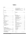
Table of Contents
Preface ................................................................................................................... i
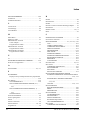
Table of Contents .......................................................................................................... ii - iv
Cautions
............................................................................................................................................... v - vi
UL Application Notes ..................................................................................................................... vii
Package Contents .......................................................................................................................... viii
Symbol Information ........................................................................................................................ ix
Chapter 1 - Introduction
1.1 Operating the GP .................................................................................................................. 1-1
1.2 System Design ........................................................................................................................ 1-2
1.3 Optional Equipment.............................................................................................................. 1-5
Chapter 2 - Specifications
2.1 General Specifications .......................................................................................................... 2-1
1. Electrical Specifications .................................................................................................................. 2-1
2. Environmental Specifications .......................................................................................................... 2-2
3. Structural Specifications .................................................................................................................. 2-2
2.2 Features and Performance ................................................................................................... 2-3
1.
2.
3.
4.
Display Features ............................................................................................................................... 2-3
Screen Memory ................................................................................................................................ 2-4
Touch Panel / Clock Accuracy ......................................................................................................... 2-4
External Interfaces ........................................................................................................................... 2-5
2.3 Interface Specifications ........................................................................................................ 2-6
1. Printer Interface ............................................................................................................................... 2-6
2. AUX I/F (Input/ Output) .................................................................................................................. 2-7
3. Serial Interface ................................................................................................................................. 2-9
2.4 Names and Functions of GP Parts..................................................................................... 2-10
2.5 Graphic Panel Dimensions ................................................................................................. 2-11
1.
2.
3.
4.
ii
GP-470 Series External Dimensions ............................................................................................. 2-11
GP-570 Series External Dimensions ............................................................................................. 2-12
Installation Fasteners ..................................................................................................................... 2-13
GP Installation Mounting Hole Dimensions .................................................................................. 2-14
GP-470/570 Series User's Manual
Chapter 3 - Installation and Wiring
3.1 Installation ............................................................................................................................. 3-1
1.
2.
3.
4.
Creating an Installation Opening ..................................................................................................... 3-1
Installation Direction ....................................................................................................................... 3-3
Securing the Installation Fasteners .................................................................................................. 3-3
Inserting and Tightening the Fasteners ............................................................................................ 3-4
3.2 Wiring Cautions .................................................................................................................... 3-5
1.
2.
3.
4.
5.
Connecting the GP's Power Cable ................................................................................................... 3-5
Connecting the GP Power Supply Terminals .................................................................................. 3-6
Connecting the GP's Power Supply ................................................................................................. 3-7
Grounding the GP ............................................................................................................................ 3-8
Placement of I/O Signal Lines ......................................................................................................... 3-9
3.3 Connecting the Printer Cable .............................................................................................. 3-9
3.4 GP Tool Connector .............................................................................................................. 3-10
Chapter 4 - OFFLINE Mode
4.1 Entering OFFLINE Mode .................................................................................................... 4-1
1. When Turning the GP's Power ON .................................................................................................. 4-1
2. From Forced Reset ........................................................................................................................... 4-2
4.2 OFFLINE Mode's Main Menu ............................................................................................ 4-3
4.3 INITIALIZE - Standard Operation .................................................................................. 4-4
4.4 SELF-DIAGNOSIS - Standard Operation ....................................................................... 4-6
4.5 Transferring Screen Data ..................................................................................................... 4-8
Chapter 5 - Initializing the GP
5.1 Initialization Screen .............................................................................................................. 5-1
5.2 Initialization Items ................................................................................................................ 5-2
5.3 SYSTEM ENVIRONMENT SETUP ................................................................................... 5-3
1.
2.
3.
4.
SYSTEM SETUP ............................................................................................................................ 5-3
SYSTEM AREA SETUP ................................................................................................................. 5-4
GLOBAL WINDOW SETUP ......................................................................................................... 5-5
CHARACTER STRING DATA SETUP ......................................................................................... 5-6
5.4 SET UP I/O ............................................................................................................................ 5-9
1.
2.
3.
4.
SET UP SIO ..................................................................................................................................... 5-9
SET UP PRINTER ........................................................................................................................ 5-10
SET UP TOUCH PANEL .............................................................................................................. 5-11
COMMUNICATION SETUP ........................................................................................................ 5-13
5.5 PLC SETUP ......................................................................................................................... 5-14
1.
2.
3.
4.
SET UP OPERATION SURROUNDINGS (1:1) .......................................................................... 5-14
SET UP OPERATION SURROUNDINGS (n:1) ......................................................................... 5-15
STATION SETUP (n:1) ................................................................................................................. 5-16
CUSTOMIZE SETUP ................................................................................................................... 5-18
GP-470/570 Series User's Manual
iii
5.6 INITIALIZE INTERNAL MEMORY .............................................................................. 5-20
5.7 SET UP TIME ..................................................................................................................... 5-20
5.8 SET UP SCREEN ................................................................................................................ 5-21
Chapter 6 - GP RUN and Errors
6.1 RUN MODE ........................................................................................................................... 6-1
1. After Powering Up The GP .............................................................................................................. 6-1
2. Via OFFLINE Mode ........................................................................................................................ 6-1
6.2 Troubleshooting ..................................................................................................................... 6-2
1.
2.
3.
4.
Possible Types of Trouble ................................................................................................................ 6-2
No Display ........................................................................................................................................ 6-4
No GP/Host Communication ........................................................................................................... 6-7
The Touch Panel Does Not Respond ............................................................................................... 6-9
6.3 GP SELF-DIAGNOSIS ...................................................................................................... 6-10
1. SELF-DIAGNOSIS Menu ............................................................................................................. 6-10
2. SELF-DIAGNOSIS - Details ....................................................................................................... 6-11
6.4 Error Messages .................................................................................................................... 6-14
1. Error Message List ......................................................................................................................... 6-14
2. Error Messages - Details .............................................................................................................. 6-15
Chapter 7 - Maintenance
7.1 Regular Cleaning .................................................................................................................. 7-1
1. Cleaning the Display .......................................................................................................... 7-1
2. Installation Gasket Check/Replacement ............................................................................ 7-1
7.2 Periodic Check-Up ................................................................................................................ 7-3
7.3 Changing the Backlight ........................................................................................................ 7-4
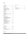
Index
iv
........................................................................................................... i - ii
GP-470/570 Series User's Manual
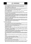
Cautions
For safe and correct use of this unit, follow these guidelines.
•
Because of the ever present danger of electric shocks, make sure the
Power Cable is not plugged in when connecting it up to the GP.
•
Whenever changing the Backlight, to prevent electric shocks or burns,
be sure to turn off the GP power and use protective gloves.
•
Because the GP is loaded with high voltage parts, electric shocks can
occur when disassembling the unit. Do not disassemble the GP.
•
Do not use power beyond the specified voltage range. If you do, it may
cause a fire or an electric shock.
•
Do not reconstruct the GP unit. It may cause a fire or an electric shock.
•
Do not use the GP in an environment with flammable gas in the
surrounding atmosphere. It may cause explosion.
•
GP uses a lithium battery for backing up its internal clock data. If the
battery is incorrectly replaced, the battery may explode. To avoid the
danger, please do not replace the battery yourself. When the battery
needs a replacement, please consult with your local GP distributor.
•
Do not use touch panel keys in any life-related or important disaster prevention situations. Use separate hardware switches for such keys.
•
Please design your system so that the machine will not malfunction by a
communication fault between the GP and its host controller. If not, there
could be a danger of injuring a person or damaging materials.
To Prevent GP Damage:
•
Never strike the touch panel with a hard or heavy object, or push on the
touch panel with too much force, since it may damage the unit.
•
If the GP is used in an environment that has temperatures in excess of the
allowed range, the GP may malfunction.
•
Do not allow water, liquids, or metal particles to enter inside the GP's
chassis, since they can cause either a GP malfunction or an electrical
shocks.
•
Avoid restricting the GP's naturally occuring ventilation, or storing or
using the GP in an environment that is too hot.
•
Avoid using or storing the GP in direct sunlight, or in excessively dusty
or dirty
GP-470/570 Series User's Manual
v
•
Avoid using or storing the GP in direct sunlight, or in excessively dusty
or dirty environments.
•
Because the GP is a precision instrument, do not store or use the GP
where powerful shocks or excessive vibration will occur.
•
Do not store or use the GP where chemicals and acids evaporate, or
where chemicals and acids are dispersed into the air.
•
Do not use paint thinner or organic solvents to clean the GP.
•
Be sure to back up all screen data regularly.
•
After turning this unit OFF, be sure to wait a few seconds before turning
it ON again. If the unit is started too soon, it may not start up correctly.
About the GP's Display Panel
• The Display Panel contents and the Contrast Adjustment affect the
intensity of Contouring. (i.e, when some parts of the screen are brighter
than others, creating a wavelike pattern)
• There are minute grid-points (dark/light) on the Display Panel's surface.
This is part of the GP's design and not a defect.
• Shadows may appear at the top of the LCD. This is normal for an LCD
display.
• Sometimes the display area may look as if the display colors have
changed. This is a common attribute of LCD's and is not a defect.
• Displaying a single image for long periods can cause an afterimage to
remain when the display is changed to another screen.
To prevent this effect:
Set the unit to "Stand-by Mode", which turns the screen OFF automatically when there is no input (a single screen display with no operations) for a specified period of time.
Do not display any single screen for a long period of time. Try to always
change the screen display periodically.
vi
GP-470/570 Series User's Manual
UL/cUL Application Notes
The GP470-EG31-**, GP570-TC31-**, and the GP570-SC31-** are all
UL1950 approved products. (UL file no. E171486) Please feel free to build
them into your product. When applying for UL approval for a machine which
includes one of these GP units, please be sure to pay special attention to the
following instruction. Machinery with built-in GP units requre UL inspection
of the combination of the GP and the machinery.
•
GP components conform to the following standards:
1950 (plus D3) Second Edition, dated February 26, 1993 (Standard for Safety
of Information Technology Equipment, including Electrical Business
Equipment)
CAN/CSA-C22.2 No. 950-M89 (plus D3) (Standard for Safety of Information
Technoloby Equipment, including Electrical Business Equipment)
The D3 deviation items are: SC1.3.4, SC1.3.8, SC2.1, SC2.9, and SC5.3.
These deviations will lose their effect as of March 15, 2000.
GP470-EG31-** (UL Registration Model: 0680029-02) Class 1
Equipment
GP570-TC31-** (UL Registration Model: 0680035-03)
GP570-SC31-** (UL Registration Model: 0680035-04)
•
Machinery which includes the GP device will also be treated as having
the D3 deviations.
•
The GP470-EG31-** power input terminal block's earth lead is a protective earth lead. This lead should be earthed in accordance with UL
standards.
•
The electric power must be supplied by an ELV circuit which complies
with Subclause 1.3.8 in the UL 1950 standard, or by a limited power
source which fulfills conditions of clause.
•
If the GP is mounted so as to cool itself naturally, please mount it on a
vertical panel. Also, insure that the GP is mounted at least 100mm away
from any other adjacent structures or machine parts. If these conditions
are not met, the heat generated by the GP's internal components may
cause it to fail to meet UL standards.
CE Marking
The GP470-EG21-** and GP570-SC21-** models are CE marked products
that conform to EMC Directive, EN55022 Class A and EN50082-2.
GP-470/570 Series User's Manual
vii
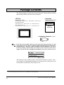
Package Contents
The GP's packing box contains the items listed below. Please check to confirm
that all items shown below have been included.
• GP Unit
(Standard models)
GP470-EG11, GP570-TC11, GP570-SC11, GP571-TC11
(CE marked models)
GP470-EG21-**, GP570-TC21-**, GP570-SC21-**
(cUL marked models)
GP470-EG31-**, GP570-TC31-**, GP570-SC31-**
• Operation
Instructions (1)*1
Operation
Instructions
GP-*70
Series Unit
• Installation fasteners (4/set)
If the GP is turned OFF while any Q tag generated alarm messages are still
Note: being displayed, only GP units equipped with backup SRAM will automatically
backup the data. Whether a unit is equipped with this SRAM or not can be
known by looking at the metallic seal on the rear face of the GP. If the seal is
copper colored, the unit is equipped with SRAM; if it is silver colored, it is not.
This unit has been carefully packed, with special attention to quality. However, should you find anything damaged or missing, please contact your local
GP distributor immediately for prompt service.
*1 This manual (GP-470/570 Series User's Manual) is sold separately.
viii
GP-470/570 Series User's Manual
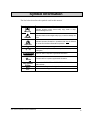
Symbol Information
The list below describes the symbols used in this manual.
Symbol
!
Warning
!
Meaning
Indicates situations where severe bodily injury, death or major
machine damage can occur.
Caution
Indicates situations where slight bodily injury or machine damage can
occur.
!
Indicates important information or procedures that must be followed
for correct and risk-free software/device operation.
*1
1) , 2)
Indicates useful or important supplemental information.
Indicates steps in a procedure. Be sure to perform these steps in the
order given.
Important
Reference
Refers to useful or important supplemental information.
Note:
Provides useful or important supplemental information.
GP Screen
Editor
PLC
n:1
Indicates the GP-PRO/PBIII or GP-PRO/PBIII for Windows 95 screen
editor software.
Abbreviation for Programmable Logic Controller.
Indicates a multi-link type of connection is used.
GP-470/570 Series User's Manual
ix
MEMO
x
GP-470/570 Series User's Manual
Chapter 1 - Introduction
Chapter 1
Introduction
1. Operating the GP
2. System Design
3. Optional Equipment
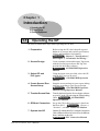
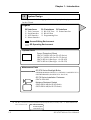
1.1
Operating the GP
Be sure to follow these steps when operating the GP unit.
1 Preparation
Before using the GP, check that all required
hardware is present and read all specification,
wiring, and installation information.
Reference
Chapter 2, "Specifications",
and Chapter 3, "Installation and Wiring"
2 Screen Design
Create a sample screen and design a Tag layout,
with the Screen layout sheets and Tag lists
provided in the Editor software.
Reference
GP-PRO/PBIII Operation
Manual
3 Select GP and
PLC types
Using the input areas provided, select the GP
and the PLC types to be used.
Reference
GP-PRO/PBIII Operation
Manual
4 Create Screen/ Run
Screen Setup
Setup the screen and tags in your screen editing
software according to your Screen Design.
Reference
GP-PRO/PBIII Operation
Manual and Tag Reference Manual
5 Transfer Screen Data
Transfer the data from the Screen design software
on your PC to the GP unit using the Downloading
Cable. Reference GP-PRO/PBIII
Operation Manual
6 GP/Host Connection
Set up the GP so that it can receive data from
the Host (PLC). Reference
Chapter 4,
"Initialize", and PLC Connection Manual
7 Operate the GP
Link the GP with the host (PLC) using the Connection
Cable (different cables may be necessary for different
hosts), and then run the unit.
Reference PLC Connection Manual
GP-470/570 Series User's Manual
1-1
Chapter 1 - Introduction
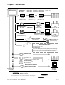
1.2
System Design
The diagram on the following pages illustrates the peripheral equipment available
for the GP unit.
Legend
GP Interfaces
• Tool Connector
‚ Serial Interface
ƒ AUX Interface
„ Printer Interface
PLC Interfaces PC Interface
… RS-232C Port ˆ Printer Interface
† RS-422 Port
‡ Programming Port
Screen Editing Environment
GP Operating Environment
Optional Parts
Cover (Protection) Sheet
GP470-COVER-*0P (for GP-470 Series)
GP570-COVER-*0P (for GP-570 Series)
GP470-DF10-O (Hard type - for GP-470)
GP570-DF10-O (Hard type - for GP-570)
Maintenance Parts
GP-570 Series Backlight Bulbs
GP570-BL00-MS (for GP570-TC**, GP570-SC**, and GP571-TC**)
GP577RT-BL00-MS (for GP570-TC21 - Rev. E *1)
GP-70 Series Installation Fasteners
GP070-AT00-MS
Moisture Resistant Gasket
GP470-WP10-MS (for GP-470 Series)
GP570-WP10-MS (for GP-570 Series)
*1 The Rev. (revision) seal can be found on the back of the unit (see below). The “*” mark indicates the
unit’s revision code.
Rev. ABCD*FGHIJ
KLMNOPQRST
UVWXYZ 123
1-2
GP-470/570 Series User's Manual
Chapter 1 - Introduction
Standard *1
GP Units
GP470-EG11 GP570-TC11 GP570-SC11 GP571-TC11
GP470-EG21 GP570-TC21 GP570-SC21
T-Link
Interface Unit
(Attaches to GP)
Profibus
Interface Unit
GP Ethernet
Interface Unit
PLC
(Attaches to GP)
(Attaches to GP)
•
CD Version
GP-PRO/PBIII
(GPW-PB01M-V*)
for Windows 95
FD Version
Ver. 2.0
(GPW-PB02M-V*)
Data Transfer
Cable
(GPW-CB-SET)
(Sold separately)
Printer
Personal
(see
next
page *4)
Computer *2
•
Data Transfer Cable
GP-PRO/PBIII
(DOS Version)
(Included with software)
(GPPRO3-PB01M-V*)
Personal
Printer
Computer *2 (Epson ESC/P24
or equivalent)
Memory Loader II
•
Memory Loader *3
(GP070-LD01-O)
(GP070-MU01-O)
•
Recommended Units:
•
Aimex Corporation:
Bar Code Reader
‚
‚
‚
‚
(Continued on
next page)
(BR-331 PC2 Pen type)
OPT Electronics:
(OPT-1125-WL98 [Touch Scanner] /WD98 [used w/keyboard])
(OPT-5125-WL98 [Touch Scanner] /WD98 [used w/keyboard])
(LT-2125-WL98 [Touch Scanner] /WD98 [used w/keyboard])
RS-232C Cable
(GP410-IS00-O)
…
RS-422 Cable
(GP230-IS11-O
(GP230-IS12-O) for Multi-link cable
RS-422 Connector
Terminal Adapter *4
†
PLC
(GP070-CN10-O)
Siemens Simatic S5 Series
Program Port I/F Cable
(GP000-IS11-O)
‡
Personal
Computer *2
*1 If the GP's rear ID sticker is copper colored, the unit is equipped with backup SRAM.
Package Contents
Reference
*2 IBM PC or compatible. (Certain non-standard PCs cannot be used) Reference
Operation Manual
*3 Cannot be used with system versions 1.20 or higher.
*4 Certain types and models of PLCs can not be connected. Reference PLC Connection Manual
GP-470/570 Series User's Manual
1-3
Chapter 1 - Introduction
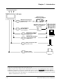
(From previous page)
GP Unit
Mitsubishi PLC
A-Series 2 Port Adaptor
‚
(GP030-MD11-O)
Mitsubishi PLC A-Series
Program Port I/F Cable*1
‡
(GP430-IP10-O)
Mitsubishi PLC A, Q, FX
Series' 2 Port Adaptor II *2
(GP070-MD11)
‚
ƒ
2 Port Adaptor II
RS-422 Cable*1
(GP070-MDCB11)
‡
‚
Mitsubishi PLC A-Series
Program Port I/F Cable
GP430-IP10-O
‡
‚
Mitsubishi PLC FX-Series
Program Port I/F Cable
GP430-IP11-O
‡
DC24V Parallel I/F Cable
PLC
Personal
Computer *3
12345
12345
12345
12345
12345
12345
12345
(supplied by user)
Signal Tower
„
Printer Cable
(Commercial type)
Printer
*1
*2
*3
*4
1-4
*4
The User can prepare and use their own cable as well.
When using the 2-Port adaptor II with a Mitsubishi FX series unit, a special Mitsubishi cable is required.
IBM PC or compatible. (Certain non-standard PCs cannot be used)
Reference Operation Manual
Dedicated Windows (95,98) printers cannot be used. Be sure,when selecting a printer, to confirm that the unit
supports HP LaserJet PCL, NEC PR Series, or EPSON ESC/P24-84 or equivalent. Certain printers with both
Windows and DOS drivers may be used.
GP-470/570 Series User's Manual
Chapter 1 - Introduction
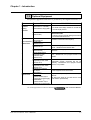
1.3
Optional Equipment
All optional equipment listed below is produced by the Digital Electronics Co.
Screen
Creation/
Editing
Software
ITEM
GP-PRO/PB III for Windows95 GP-PRO/PB III
(GPW-PB01M-V*<CD-ROM>)
PC based screen design software for use with GP(GPW-PB02M-V*<Floppy disk>)
70 series display screens.
Data Transfer Cable Set
(GPW-CB-SET)
RS-232C Cable
(GP410-IS00-O)*1
Serial Interface
RS-422 Cable
Cables/Units
(GP230-IS11-O) *1
Multi-link Cable
(GP230-IS12-O) *1
Option Items
DESCRIPTION
Data Transfer Cable
Connects your PC to the GP, allowing screen data to
be transferred between the two.
I/F cable to connect GP to the Host (PLC).
Allows multi-link (n:1) SIO between the Host (PLC) and
the GP. Standard RS-422 interface cable.
RS-422 Terminal Adapter
(GP070-CN10-O)
Adapter for converting output from a serial interface to
RS-422 I/F.
Siemens Simatic Series
Programming Port I/F
Connection Cable
(GP000-IS11-O)
Mitsubishi A Series
Programming Port I/F cable
(GP430-IP10-O)
Mitsubishi PLC FX Series
Programming Port I/F Cable
(GP430-IP11-O)
Mitsubishi PLC A Series 2
Port Adapter
(GP070-MD11)
TTY converter cable for Siemens Simatic S5 Series
PLCs. Simultaneous use of program console is not
possible.
Cover Sheets
GP-470 Series
(GP470-COVER-*0P) or
(GP470-DF10-O) [hard type]
GP-570 Series
(GP570-COVER-*0P) or
(GP570-DF10-O) [hard type]
Connects directly to Mitsubishi's FX Series I/F
Programming Console. Conversion link unit not
necessary. Simultaneous use of program console,
however, is not possible.
Interface unit that allows use of both GP and Mitsubishi
A series equipment in the same location.
Disposable sheets provide protection from a variety of
elements.
The GP's touch panel can be used with this cover
sheet attached. (20 sheets/set)
*1 Certain types of PLC's cannot be connected.
GP-470/570 Series User's Manual
Reference
PLC Connection Manual.
1-5
Chapter 1 - Introduction
Maintenance
Parts
Data Copy
Units
GP-570 Backlight Bulbs
GP-570 Series
(GP570-BL00-MS)
*1
(GP577RT-BL00-MS)
Installation Fasteners
(GP070-AT00-MS)
Moisture Resistant Gasket
GP-470 Series
(GP470-WP10-MS)
GP-570 Series
(GP570-WP10-MS)
Installation fasteners for GP-70 series units.
Used when installing the GP to provide a moisture
resistant seal.
Same as the seal included in the GP’s original
equipment package.
Copies data at high speed from one GP to another.
2
Memory Loader*
(GP070-MU01-O)
(Both system program and screen data)
3
Memory Loader II*
(GP070-LD01-O)
Replacement backlight bulbs for GP-570 series units.
Copies data at high speed from one GP to another.
(Both system program and screen data)
*1 With GP570-TC21 units that are Rev. E, when changing the backlight, be sure to use
backlight model GP577RT-BL00-MS.
*2 Cannot be used with system versions 1.20 or higher.
*3 Certain functionality present in the Japanese unit is not available in the English unit.
!
Important
The Rev. (revision) seal can be found on the back of the unit (see
below). The "*" mark indicates the unit’s revision code.
Rev. ABCD*FGHIJ
KLMNOPQRST
UVWXYZ 123
1-6
GP-470/570 Series User's Manual
Chapter 2
Specifications
1. General Specifications
2. Features and Performance
3. Interface Specifications
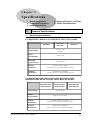
2.1
1.
4. Names and Functions of GP Parts
5. Graphic Panel Dimensions
General Specifications
Electrical Specifications
For GP470-EG11, GP570-TC11, GP570-SC11, GP571-TC11 models.
GP470-EG11
GP570-TC11
GP571-TC11
Input Voltage
AC 85V to 132V
50/60 Hz
Power
Consumption
Under 50 VA
Allowable
Power Failure
Less than 20mS
GP570-SC11
Voltage
Endurance
AC1500V--20mA 1minute
(between the live wire and grounding terminals)
Isolation
Resistance
DC500V--above 10MOhm
(between the live wire and grounding terminals
For GP470-EG21-24VP, GP570-TC21-24VP, GP570-SC21-24VP,
GP470-EG31-24V, GP570-TC31-24V, GP570-SC31-24V models.
GP470-EG21-24VP
GP470-EG31-24V
GP570-TC21-24VP
GP570-TC31-24V
Input Voltage
DC 24V±20%
Power
Consumption
Under 50 W (TYP 20W)
GP570-SC21-24VP
GP570-SC31-24V
Voltage
Endurance
AC1000V (10mA for 1 minute)
between the live wire and grounding terminals
Isolation
Resistance
DC500V (above 10MOhm)
between the live wire and grounding terminals
GP-470/570 Series User's Manual
2-1
Chapter 2 - Specifications
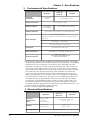
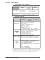
2.
Environmental Specifications
GP570-TC**
GP571-TC**
GP470-EG**
Operating
Temperature
0 to 50 degrees
Celsius
0 to 40 degrees Celsius
Storage Temperature
-10 to 60 degrees Celsius
20 to 85%RH
(non-condensing)
Ambient Humidity
Vibration Endurance
GP570-SC**
30 to 85%RH (non-condensing)
10 to 25 Hz (X,Y,Z directions 30 minute each 2G)
Noise voltage: 1200 Vp-p
However, for GP*70-**21 and GP*70-**31 models, the level is
1000 Vp-p
Noise Endurance
Pulse length: 1 microsecond
Arise time (rise/fall): 1 nanosecond
Atmosphere
Not imm une to corrosive gas
Ground Connection
Groundin
resistance
under2 100
Ohmswire. *2
Less
than g100
Ω/ Use 2mm
or larger
Suitable
for IP65F,
Equivalent
to IP65f
(JEM1030) and
NEMA
#250
NEMA #250TYPE4X/13
TYPE4X/12
*1
Protective Structure
(Does not protect against freezing)
*1 The front face of the GP unit, installed in a solid panel, has been tested using
conditions equivalent to the standards shown in the specification . Even though
the GP unit’s level of resistance is equivalent to these standards, oils that
should have no effect on the GP can possibly harm the unit. This can occur in
areas where either vaporized oils are present, or where low viscosity cutting
oils are allowed to adhere to the unit for long periods of time. If the GP’s front
face protection sheet becomes peeled off, these conditions can lead to the
ingress of oil into the GP and separate protection measures are suggested.
Also, if non-approved oils are present, it may cause deformation or corrosion
of the front panel’s plastic cover. Therefore, prior to installing the GP be sure
to confirm the type of conditions that will be present in the GP’s operating
environment. If the installation gasket is used for a long period of time, or if
the unit and its gasket are removed from the panel, the original level of the
protection cannot be guaranteed. To maintain the original protection level, you
need to replace the installation gasket regularly.
*2 Use your country's applicable grounding.
3. Structural Specifications
GP470-EG**
E xternal
D im ensions
(m m )
274W x 216H x
56.5D m m
(GP unit only)
W eight
Under 2.5 kg
(GP unit only)
C ooling System
2-2
GP570-TC**
GP571-TC**
GP570-SC**
317W x 243H x 85D m m
(GP unit only)
Under 3.5 kg
(GP unit only)
Natural air circulation
GP-470/570 Series User's Manual
Chapter 2 - Specifications
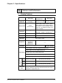
2.2
1.
Features and Performance
Display Features
GP570-TC**
GP571-TC**
GP470-EG
Display
Medium
High Intensity
EL Display
GP570-SC**
TFT type color LCD STN type color LCD
8 colors (white, red blue, green, yellow,
purple, light blue, black) Tiling patterns
make blends of colors possible. Only the
GP571-TC** can display 64 colors on its
Image (I) screens.
Display Color
Amber
(monochrome)
Backlight
----
Resolution
640 x 400 pixels
640 x 480 pixels
Display Area
192W x 120H
211W x 158H
Contrast
humidity, lifespan = 20,000 hours
*1
)
Blink/ Reverse video
Attributes
Brightness
CFL (under normal temperatures and
Touch Panel has
two levels of
Brightness
adjustments.
---------
8 levels available
Korean: (KSC5601-1992 codes) Hangul fonts (including Kanji)
Chinese: (GB2321-80 codes) simplified Chinese fonts
Characters Taiwanese: (Big 5 codes) traditional Chinese fonts
ASCII :(Code Page850) Alphanumeric (including European fonts)
Japan: ANK 158 type, Kanji:6349 (Standard JIS Type 1 and Type 2)
8x8
80 Char. per row, 60 rows
80 Char./row,50rows
dot font
No.
of
8x16
80 Char. per row, 30 rows
80 Char./row, 25rows
Char. dot font
Disp 16x16
40 Char./row,25rows
40 Char. per row, 30 rows
dot font
Both height and width can be expanded 1, 2, 4, or 8 times.
Character
Chinese characters larger than 2 times size (32 x 32) can be
Size
displayed in a high quality font.
GP-470/570 Series User's Manual
2-3
Chapter 2 - Specifications
Note:
Since it uses more colors, the display and printing speeds of the GP571-TC**
are slower than the GP570-TC**.
*1 With GP570-TC21 units that are Rev. E, the estimated lifetime of the backlight is 40,000
hours (assuming 24 hour operation).
!
Important
• The Rev. (revision) seal can be found on the back of the unit (see
below). The “*” mark indicates the unit’s revision code.
Rev. ABCD*FGHIJ
KLMNOPQRST
UVWXYZ 123
2.
Screen Memory
GP470-EG**
Internal
Memo ry
Backup *1
Memo ry
GP570-TC**
GP571-TC**
GP570-SC**
FLASH EPROM 1M byte
(approx. 320 screens, 3.2K bytes/screen)
However, GP571-TC** has 3M bytes
(approx, 960screens, 3.2k bytes/screen).
SRAM 32K bytes (768 messages)
The Backup Memory uses Lithiumbatteries.
*2
*1 Ony available on units with backup SRAM built in.
*2 The battery life of the GP-470/570's lithium battery, when the battery is 40oC or less, is
over 10 years. At 50oC or less it is over 4.1 years, and at 60oC or less it is more than 1.5
years.
2-4
GP-470/570 Series User's Manual
Chapter 2 - Specifications
3.
Touch Panel / Clock Accuracy
GP470-EG**
Touch Panel
32x20 keys/ screen
(1 or 2 point touch)
Clock Accuracy
4.
GP570-TC**
GP571-TC**
GP570-SC**
32 x 24 keys/ screen
(1 or 2 point touch)
+/- 65 seconds/ month (at room temperature)
External Interfaces
GP470-EG**
Serial Interface
Auxiliary
Input/Output
(AUX)
Printer Output
Tool
Connector
I/F
GP570-TC**
GP571-TC**
GP570-SC**
Asynchronous Transmission Method:
RS232C/RS422
(Supports various PLC protocols)
Data Length: 7 or 8 bits
Stop Bit: 1 or 2 bits
Parity: None, Odd or Even
Data Transmission Speed: 2400 to 115.2kbps
Touch Switch Output (for inching): DC 24V 8 points
System Alarm Output: DC24V 1 point
Buzzer Output: DC24V 1 point
RUN Ouput: DC24V 1 point
Remote Reset Input: DC24V 1 point
Conforms to Centronix standards
(HP LaserJet PCL4 compatible, NEC PR series,
EPSON ESC/P24 or equivalent can be connected)
RS-232C Asynchronous Transmission Method, TTL
level non-procedural command interface
During Program Development Connect the data transfer cable to download screen
data
During GP RUN mode Connect a Bar-code reader
1) Dedicated Windows (95,98) printers cannot be used. Be sure,when selecting a printer, to
confirm that the unit supports HP LaserJet PCL, NEC PR Series, or EPSON ESC/P24-84 or
equivalent. Certain printers with both Windows and DOS drivers may be used.
GP-470/570 Series User's Manual
2-5
Chapter 2 - Specifications
2.3
1.
Interface Specifications
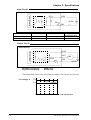
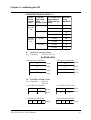
Printer Interface
Pin Connection
7
14
1
8
Pin
#
Signal
Name
1
PSTB
2
PDB0
3
PDB1
4
PDB2
5
PDB3
6
PDB4
7
PDB5
8
PDB6
9
PDB7
*1
10
INIT
11
BUSY
12
Reserved
13
Reserved
14
GND
*1 When the INIT signal is not used, no.10 pin does not need to be connected.
Recommended Connector
Recommended Cover
!
Important
2-6
: FCN-787P014-G/R (made by Fujitsu, Inc.)
: FCN-780C014-D/E (made by Fujitsu, Inc.)
Do not connect pins 12 and 13 to anything.
GP-470/570 Series User's Manual
Chapter 2 - Specifications
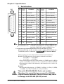
2.
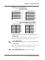
AUX I/F (Input/ Output)
Pin Connection
Pin #
Signal
Name
1
TSW0
2
TSW1
3
TSW2
4
TSW3
5
TSW4
6
TSW5
7
TSW6
8
TSW7
9
RUN
Output On in the middle of operations,
Off during Power interuption or in standby
mode
10
ALARM
Alarm Output: when On, enables GP unit
alarm.*1
11
BUZZ
Buzzer Output
12
DC24V
Output--Common (DC24V)
13
AIN - C
Input--Common (DC24V)
14
AOUT - C
Output--Common (GND)
15
RESET
Contents
Touch Switch Output (8 bit)
Reset Input
*1 AUX Input/Output I/F's pin no.10 Alarm
The AUX Alarm will occur in the following two cases:
• Hardware Alarm (SCREEN MEMORY CHECKSUM ERROR)
• Software Alarm (SYSTEM ERROR, i.e., incorrect data that makes screen operation impossible)
Dsub15 pin Plug : XM2A-1501 (made by Omron Corp.)
Dsub15 pin Cover : XM2S-1511 (made by Omron Corp.)
Screws
: XM2Z-0071 (made by Omron Corp.)
Note:
Use rough metric type M2.6x0.45p threads used to hold the cable's set (fastening)
screws in place.
GP-470/570 Series User's Manual
2-7
Chapter 2 - Specifications
Input Circuit
Input Section
Internal Circuit
560
COM
5.6k
Input Voltage
DC 24V +/- 10%
Operating Voltage
Input Current
Min. Input Pulse Width
4mA/DC 24V (TYP)
2ms
Termination Type
DC24V
DIN
ON Voltage min. DC 21.1V
OFF Voltage max. DC 3V
Photo-Coupler Terminator
Output Circuit
Output Section
Internal Circuit
DC24V
DOUT
330P F
COM
DC24V
22
Maximum Load Current
Regulated Load Voltage
Load
50mA / point
DC24V (TYP)
The relationship between the Load Voltage and the Load Current is as follows:
Load Voltage: V
23
22.8
20.0
0
2-8
10
20
30
40
50
Load Current: mA
GP-470/570 Series User's Manual
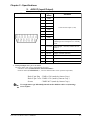
Chapter 2 - Specifications
3.
SIO
25
14
13
1
Serial Interface
Pin
#
Signal
Name
1
FG
2
Condition
Condition
Pin
#
Signal
Name
Frame ground
14
VCC
5V ± 5% output 0.25A
SD
Send data (RS-232C)
15
SDB
Send data B (RS-422)
3
RD
Receive data (RS-232C)
16
RDB
Receive data B (RS-422)
4
RS
Request send (RS-232C)
17
NC
No connection
5
CS
Clear send (RS-232C)
18
CSB
Clear send B (RS-422)
6
NC
No connection
19
ERB
Enable receive B (RS-422)
7
SG
Signal ground
20
ER
Enable receive (RS-232C)
8
CD
Carrier detect (RS-232C)
21
CSA
Clear send A (RS-422)
9
TRMX
Termination (RS-422)
22
ERA
Enable receive A (RS-422)
10
RDA
Receive data A (RS-422)
23
RESERVED
11
SDA
Send data A (RS-422)
24
NC
12
NC
No connection
25
RESERVED
13
NC
No connection
Reserved for future use
No connection
Reserved for future use
Note: Recommended Connector: Dsub25pin plug XM2A-2501<made by OMRON Corp.>
Recommended Cover : Dsub25pin Cover XM2S-2511<made by OMRON Corp.>
Jack Screw XM2Z-0071<made by OMRON Corp.>
Use rough metric type M2.6x0.45p threads used to secure the cable's set screws.
Recommended Cable : CO-MA-VV-SB5S x 28AWG <made by HITACHI Cable Ltd.>
To determine your PLC's connection: Reference PLC Connection Manual
When creating your own cable, follow the instructions listed below:
RS-422 (The following pairs of pin #'s must be connected to each other)
#18 (CSB) <—> #19 (ERB)
#21 (CSA) <—> #22 (ERA)
• When connecting the RS-422 cable and the #9 (TRMX) and #10 (RDA)
points, a termination resistance of 100Ω is added between RDA and RDB.
• When making a cable for the Memory Link format, be sure to select a 4line System.
RS-232C
• Do not use the following pins: 9 (TRMX), 10 (RDA), 11 (SDA), 15 (SDB),
16 (RDB), 18 (CSB), 19 (ERB), 21 (CSA), 22 (ERA).
This unit’s RS-485 (RS-422) Port is not isolated.
Therefore, it is crucial that you connect the SG/GND
(Signal Ground) terminals. Failure to do so may result
in damage to the RS-485 (RS-422) circuit.
GP-470/570 Series User's Manual
2-9
Chapter 2 - Specifications
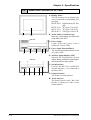
2.4
Names and Functions of GP Parts
A: Display Panel
The GP monitor screen displays the
screen setup and corresponding PLC
host data.
GP470-EG** High Intensity EL Display
GP570-TC** TFT type Color LCD
GP571-TC** TFT type Color LCD
GP570-SC** STN type Color LCD
C
B: Touch Panel (overlaid on top)
Runs any screen change operations and
sends data to the PLC.
A,B
GP-470
C: Power Lamp
Lights when the power cord is
connected. (Green LED)
D
E
F
G
GP-570
H
D: Power Input Terminal Block
The input and ground terminals for the
AC power cable.
E: Auxilary Input/Output (AUX)
Operates the Touch Switch, System
Alarm, Buzzer, and RUN output signals,
and Remote Reset input signals.
F: Serial Interface
Used for the RS-232C and RS-422
(Serial) interfaces. Are connected to
the Host (PLC).
D
E
F
G
H
G: Printer Interface
The Printer is connected here.
H: Tool Connector
The Data Transfer cable, Bar Code
Reader or Memory Loader can be
connected here.
2-10
GP-470/570 Series User's Manual
Chapter 2 - Specifications
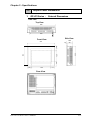
2.5
1.
Graphic Panel Dimensions
GP-470 Series -
External Dimensions
Unit: mm
Top View
258
220
10
Side View
Front View
56.5
274
49
200
48
120
216
(48)
7.5
(41)
192
41
Rear View
GP-470/570 Series User's Manual
2-11
Chapter 2 - Specifications
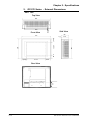
2.
GP-570 Series - External Dimensions
Unit: mm
Top View
301
263
Front View
Side View
10
85
317
77.5
227
42.3
243
158.4
(42.3)
7.5
(52.9)
211.2
52.9
50
Rear View
2-12
GP-470/570 Series User's Manual
Chapter 2 - Specifications
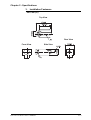
3.
Installation Fasteners
Unit: mm (in.)
Top View
Rear View
Front View
GP-470/570 Series User's Manual
Side View
2-13
Chapter 2 - Specifications
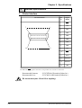
4.
GP Installation Mounting Hole Dimensions
Unit: mm
Installation Mounting Hole
GP-470 Series
259 +
GP-570 Series
1
0
1
0
302 + 0.5
12345678901234567890
12345678901234567890
12345678901234567890
12345678901234567890
12345678901234567890
12345678901234567890
12345678901234567890
12345678901234567890
12345678901234567890
12345678901234567890
12345678901234567890
12345678901234567890
12345678901234567890
12345678901234567890
12345678901234567890
less than 4-R2
2-14
228 + 0.5
201 +
12345678901234567890
12345678901234567890
12345678901234567890
12345678901234567890
12345678901234567890
12345678901234567890
12345678901234567890
12345678901234567890
12345678901234567890
12345678901234567890
12345678901234567890
12345678901234567890
12345678901234567890
12345678901234567890
12345678901234567890
less than 4-R2
GP-470/570 Series User's Manual
Chapter 3
Installation and Wiring
1. Installation
2. Wiring Cautions
3.1
3. Connecting the Printer Cable
4. GP Tool Connector
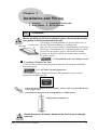
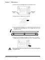
Installation
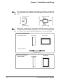
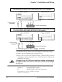
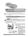
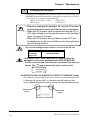
Before installing the GP into a cabinet or panel, check that the installation gasket is securely attached to the unit.
It is strongly recommended that you use the gasket since it
Installation gasket absorbs vibration in addition to repelling water.
Rear of GP
Place the GP on a level surface with the display panel facing
downward. Check that the GP’s installation gasket is seated
securely into the gasket’s groove, which runs around the
perimeter of the panel’s frame. For details about installing
the gasket, refer to
7.1.2 Installation Gasket Check/Replacement
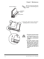
n Creating a Panel Cut Out
Create the correct sized opening required to install the GP, using the installation
dimensions given.
2.5.3 “GP Panel Cut Out Dimensions”
The installation gasket, installation brackets and attachment screws are all required when installing the GP.
Panel
Cut Out
Area
• Check that the installation panel or cabinet's surface is flat, in good condition and
has no jagged edges.
• Panel thickness should be from 1.6mm (0.06in.) to 5.0mm (0.2in.).
1.6mm(0.06in.) to 5mm(0.2in.)
Decide the panel’s thickness based on the level of panel strength
required.
GP-470/570 Series User's Manual
3-1
Chapter 3 - Installation and Wiring
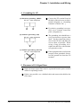
Note:
Note:
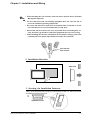
• For easier maintenance and operation, plus better ventilation, ensure the GP
unit is mounted at least 100 mm away from adjacent structures and other
parts.
• The GP uses ventilation in its outer shell to naturally cool itself. When installing the unit horizontally or sideways, use a forced air cooling system
(i.e. a fan) or lower the surrounding temperature to avoid overheating.
Horizontal Installation
(Landscape style)
Side View
Front View
(Looking down at)
Vertical Installation
(Portrait Style)
3-2
Side View
Front View
GP-470/570 Series User's Manual
Chapter 3 - Installation and Wiring
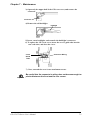
Note:
• When installing the GP vertically, orient the unit so that the Power Terminal
Block points upwards.
• Be sure that heat from surrounding equipment does not cause the GP to
exceed its standard operating temperature.
• Do not use GP-470 Series units in an environment that exceeds 50o C; do not
use GP-570 Series in an environment that exceeds 40o C.
• Ensure this unit is located as far away as possible from electromagnetic circuits, non-fuse type breakers, and other equipment that can cause arcing.
• When installing the GP unit, with natural air circulation cooling system, onto
a slanted panel, the panel slope should not incline more than 30o.
less than 30o
from vertical
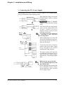
2. Installation Direction
Panel
Side View
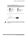
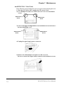
3. Securing the Installation Fasteners
There are 4 insertion slots on the top and bottom of the GP, where the metal
installation fasteners hook on.
•
Top/Bottom View
GP-470/570 Series User's Manual
3-3
Chapter 3 - Installation and Wiring
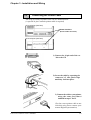
4. Inserting and Tightening the Fasteners
Insert each of the fasteners into its slot as shown below. Be sure to pull the
fastener back until it is flush with the rear of the attachment hole.
Panel
Front Side
Rear Side
Insertion
Slot
Use a screw driver to tighten the attachment screws and secure the GP unit in
place.
!
Important
3-4
A torque of only 0.5~0.6 N•m is required to tighten an attachment
screw. Be careful not tu use too much force, since it may damage
the GP unit.
GP-470/570 Series User's Manual
Chapter 3 - Installation and Wiring
3.2
Wiring Cautions
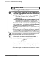
1. Connecting the GP's Power Cable
!
Warning
• To avoid electric shocks, be sure the Power Cable is
unplugged from the power outlet when connecting the
cable to the GP unit.
• The following units use an input voltage of AC100V:
GP470-EG11, GP570-TC11, GP570-SC11,
GP571-TC11
and the following units use an input voltage of DC24V:
GP470-EG21-**, GP470-EG31-**, GP570-TC21-**,
GP570-TC31-**, GP570-SC21-**,GP570-SC31-**
Be sure to use the correct power supply for your GP
unit, since using an incorrect power supply may
damage both the power source and the GP.
• Please connect a breaker unit as a power switch for
your GP.
• When connecting the GP power cord's power terminals,
be sure to ground the
terminal, since there is
possibility of an electric shock if the GP malfunctions.
When the FG terminal is connected, be sure the wire is grounded.
Not grounding the GP unit will result in excess noise.
Important
!
Note:
• Wherever possible, use thick wires (max 2mm2) for power terminals, and
twist the exposed wire ends when connecting the Ring Terminals.
• Please use Ring Terminals with the size described below.
over Ø3.2mm
under Ø6.0mm
• To prevent the Ring Terminals from causing a short when the terminal block
attachment screws are loosened, be sure to use sleeve-type Ring Terminals.
• Do not wire the cable either near or parallel to high voltage or high current
power lines.
• Be sure that any DC24V power line used provides sufficient power for the GP
and that the voltage does not fluctuate.
GP-470/570 Series User's Manual
3-5
Chapter 3 - Installation and Wiring
For GP470-EG11, GP570-TC11, GP570-SC11, GP571-TC11 models
Rear of GP-470
Crimp-on Ring
Terminals *1
L
N
FG
Rear of GP-570
L
N
FG
Power Terminal Block
For GP470-EG21-24VP, GP470-EG31-24V, GP570-TC21-24VP, GP570TC31-24V, GP570-SC21-24VP, GP570-SC31-24V models.
Rear of GP-470
Crimp-on Ring +
Terminals *1
-
FG
+
Rear of GP-570
-
FG
Power Terminal Block
2. Connecting the GP Power Supply Terminals
1) Be sure that the GP's Power Cord is not plugged in to the power supply.
2) Remove the GP Terminal Strip's clear plastic cover.
3) Remove the screws from the 3 middle terminals, position the Ring Terminals
as shown above and re-attach the screws. (Check each wire to make sure the
connections are correct)
!
Important
A torque. of only 0.5~0.6 N•m is required to tighten an attachment
screw. Be careful not tu use too much force, since it may damage
the GP unit.
*1 The three ring terminals are:
AC100V L
= AC Input Terminal - live line
AC100V N
= AC Input Terminal - neutral line
FG
= Ground terminal - connected to the GP chassis
Recommended ring terminal: V2-MS3 or equivalent
(Made by JST Corporation)
3-6
GP-470/570 Series User's Manual
Chapter 3 - Installation and Wiring
3. Connecting the GP's Power Supply
When using the 470-EG11, 570-TC11, 570-SC11 and 571-TC11 models, please
pay special attention to the following items.
•
Twisted Lines
voltage
transformer
GP unit
If the supplied voltage exceeds the
GP unit's range, connect a voltage
transformer.
Reference Chapter 2, "Specifi-
cations", for the allowable voltage
range.
Twisted Lines
noise
reducing
transformer
M a i n GP
Power power
GP unit
•
Use Voltage and Noise Reducing
Note: transformers with capacities
GP unit
exceeding 100VA.
input/output unit
•
When supplying power to the GP
unit, please separate the input/output and operation unit lines as
shown in the figure.
•
To increase the noise resistance
quality of the power cable, simply
twist each power wire before
attaching the Ring Terminal.
•
The power supply cable must not
be bundled or positioned close to
main circuit lines (high voltage,
high current), or input/output signal
lines.
M a i n GP
Power power
GP unit
power
input/output
Input/ Output Power
Input/ Output Power
main circuit
Operation
Unit
Motor
GP unit
surge
absorber
GP-470/570 Series User's Manual
For between the line and ground,
select a power supply that is low
in noise. If there is an excess
amount of noise, connect a noise
reducing transformer.
• Make sure the surge absorber
Note: (E1) is grounded separately from
the GP unit (E2).
• Select a lightning surge absorber that
has a maximum circuit voltage
greater than that of the expected
power supply surges.
3-7
Chapter 3 - Installation and Wiring
4. Grounding the GP
(a) Exclusive grounding (BEST)
GP unit other equipment
Connect the FG terminal found at
the back of the unit to an exclusive
ground. [diagram (a). Grounding
resistance of under 100Ω.]
If exclusive grounding is not possible, use a common connection
point. [diagram (b)]
(b) Common grounding (OK)
GP unit other equipment
(c) Common grounding (Not OK)
GP unit other equipment
The grounding wire should have a
cross sectional area greater than
2mm2. Set the connection point as
close to the GP unit, and make the
wire as short, as possible. When
using a long grounding wire,
replace the thin wire with a thicker
wire placed in a duct.
If this equipment does not function
properly when grounded, disconnect the ground wire from the FG
terminal.
5. Placement of I/O Signal Lines
Input and output signal lines must be separated from the power control
cables for operating circuits.
If this is not possible, use a shielded cable and connect the shield to the
GP's frame.
3-8
GP-470/570 Series User's Manual
Chapter 3 - Installation and Wiring
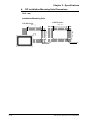
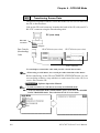
3.3
Connecting the Printer Cable
The steps to connect a printer to the GP are outlined below.
(A special 14 pin Centronix printer cable is required)
GP-470 Series (rear face)
Printer Interface
(Printer Cable Connector)
GP-570 Series (rear face)
1) Connect the 14 pin end of the cable to the GP.
2) Secure the cable by squeezing the
connector's 2 side pinch-clips
until they lock into place.
3) Connect the cable to your printer,
using the same procedures
outlined in steps 1 and 2.
(For the correct printer cable to use
with this unit, please contact your
nearest Digital representative)
GP-470/570 Series User's Manual
3-9
Chapter 3 - Installation and Wiring
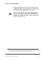
3.4
GP Tool Connector
The GP's Data Transfer Cable or a Bar Code Reader are attached to the GP via
the Tool Connector socket.
GP-470 Series (rear face)
Tool Connector
Socket
GP-570 Series (rear face)
!
Important
• Before unplugging any connector(s) from the back of the GP, be
sure the GP's power cable is unplugged from the main power
supply.
• When the Bar Code Reader uses a separate power supply:
- Turn the Bar Code Reader ON before turning the GP ON.
- Turn the GP OFF before turning the Bar Code Reader OFF.
3-10
GP-470/570 Series User's Manual
Chapter 4
OFFLINE Mode
1. Entering OFFLINE Mode 4. SELF-DIAGNOSIS—Standard Operations
2. Main Menu
5. Transfer Screen Data
3. INITIALIZE—Standard Operations
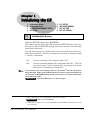
4.1
Entering OFFLINE Mode
OFFLINE Mode provides access to the Initialize, Self-Diagnosis, and other
features built into the GP. You will need to change the GP to OFFLINE mode
before you can use any of these features.
OFFLINE mode is unavailable in a completely new GP until the
necessary Screen Data has been transfered from the screen editor
Important software.
!
To INITIALIZE the setup or run SELF-DIAGNOSIS in the GP unit, transferring to
the OFFLINE mode becomes necessary. There are two ways to enter OFFLINE
mode; first, just after plugging in the unit's power, and second, by using the
Force Reset feature.
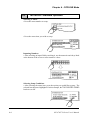
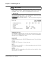
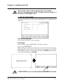
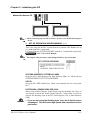
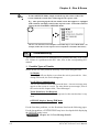
1. When Turning the GP's Power ON
Press the top left corner of the GP screen within 10 seconds of plugging in the
GP's power cord.
System Version
Current Date/Time
Protocol Name and Protocol Version
Users wishing to use the Memory Loader (GP070-MU01-O) to upload data must
Note: check that the System Version is 1.18 or lower. The Memory Loader II (GP070LD01-O), however, does not have this limitation.
GP-470/570 Series User's Manual
4-1
Chapter 4 - OFFLINE Mode
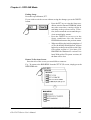
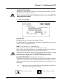
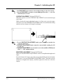
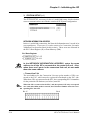
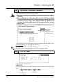
2.
From Forced Reset
From the Forced Reset screen, press the OFFLINE button.
Note: When the GP unit has the Device Monitor function, the following display will appear.
Reference GP-PRO/PBIII for Windows 95 PLC Connection Manual,
Appendix 3 - Device Monitor
SWITCH MON. OFFLINE RESET
CANCEL
MODE
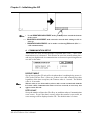
Note: • Only GP-PRO/PBIII for Windows 95 can utilize the Device Monitor function.
• If a Password has been set in INITIALIZE/ SET UP SYSTEM, before entering the
OFFLINE mode, the following screen displays.
Enter the password, then press Set to enter OFFLINE mode.
For more about the Password,
ENVIRONMENT SETUP".
Reference Chapter 5.3, "SYSTEM
For more information on the Password input,
"Inputting Numbers".
4-2
Reference Chapter 4.3,
GP-470/570 Series User's Manual
Chapter 4 - OFFLINE Mode
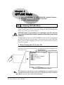
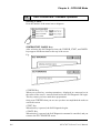
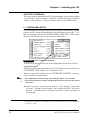
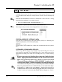
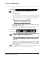
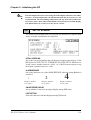
4.2
OFFLINE Mode's Main Menu
The Main Menu includes the setup items listed below: INITIALIZE, SCREEN
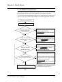
DATA TRANSFER, SELF-DIAGNOSIS, and RUN. Each menu item has different
setups that must be set to match the corresponding PLC in order for the GP to
communicate properly.
Entering the OFFLINE mode displays the screen illustrated below.
Select the menu item by pressing the corresponding number on the screen.
A short description of each Main Menu item follows.
INITIALIZE
The setup items listed in this menu are necessary to run the GP unit.
SCREEN DATA TRANSFER
Select to transfer screen data to and from the screen editing software.
SELF-DIAGNOSIS
Checks to see if there are any problems with the GP System or Interface (I/F).
RUN
Starts GP Operation.
Reference For more information about INITIALIZE, refer to Chapter 5, "Ini-
tialize"; for more information about TRANSFER SCREEN DATA, refer to your
Software Operation Manual; for more information about SELF-DIAGNOSIS
and RUN, refer to Chapter 6, "Run and Errors".
GP-470/570 Series User's Manual
4-3
Chapter 4 - OFFLINE Mode
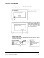
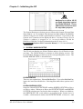
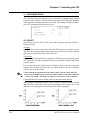
4.3
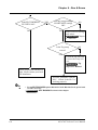
INITIALIZE—Standard Operation
Selecting A Menu
• Press the menu number to setup.
• Press the menu item you wish to setup.
Inputting Numbers
• After selecting an input field by touching it, use the numeric touch keys lined
at the bottom of the screen to enter numeric values.
Selecting Setup Conditions
• After selecting the menu item, press the option you would like to setup. The
selected item becomes highlighted. In this example, the TOUCH BUZZER SOUND
has been set Off.
4-4
GP-470/570 Series User's Manual
Chapter 4 - OFFLINE Mode
Ending Setup
Press the top-left button, SET.
If you wish to exit the screen without saving the changes, press the CANCEL
button.
•
Press the SET key to write the Setup conditions onto the Internal FEPROM, which
may take some time, causing a delay in
returning to the previous screen. Therefore, do not touch the screen until the previous menu display returns.
•
Press the CANCEL key to not write the
Setup conditions onto the Internal
FEPROM and return to the previous menu.
•
When modifying the initial setting data of
a GP with backup SRAM built in, all data
backed up to that point will be saved if the
GP's system version is 1.30 or later. (GPPRO/PBIII for Windows 95 version 2.0 or
later) With earlier GP system versions, all
the data will be lost.
Return To Previous Screen
Press the title of the screen you would like to return to.
E.g. To return to the MAIN MENU from the SET UP I/O screen, simply press the
MAIN MENU title.
GP-470/570 Series User's Manual
4-5
Chapter 4 - OFFLINE Mode
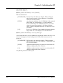
4.4
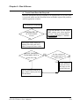
SELF-DIAGNOSIS—Standard Operation
Selecting A Menu
Press the number of the menu item to diagnose.
CONFIRM, START, CANCEL Keys
After selecting the Self Diagnosis item, the CONFIRM, START, and CANCEL
keys appear at different times at the top of the screen.
E.g.
• CONFIRM Key
When you see this key, certain preparations—displayed in a message box in
the center of the screen—must be made before the Self-Diagnosis can begin.
This key ensure you have made these preparations.
Only press CONFIRM when you are sure you have accomplished the tasks set
out on the screen.
• START Key
When this key is pressed, the Self-Diagnosis begins.
• CANCEL Key
When this key is pressed, the Self-Diagnosis command is cancelled, and you
return to the SELF-DIAGNOSIS menu.
4-6
GP-470/570 Series User's Manual
Chapter 4 - OFFLINE Mode
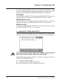
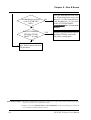
After Check—To Return To SELF-DIAGNOSIS MENU
When OK displays
Pressing once anywhere on the
display screen returns you to the
SELF-DIAGNOSIS MENU.
When an Error Message displays
When an error message appears
on the display screen, press the
bottom two corners of the panel
(1, 2) to return to the
SELF-DIAGNOSIS MENU.
Return To Main Menu
Press the RETURN Key in the top right corner of the SELF-DIAGNOSIS menu to
return to the MAIN MENU.
GP-470/570 Series User's Manual
4-7
Chapter 4 - OFFLINE Mode
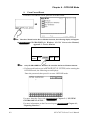
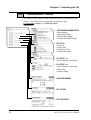
4.5
Transferring Screen Data
The process required to transfer screen data to the GP, or to receive data from
the GP, is described here.
Link up the GP's tool connector, located at the back of the GP, with your PC's
RS-232C connector using the Downloading cable.
PC (rear view)
RS-232C
connector
Adapter
Data Transfer
(Downloading)
Cable
GP-470 Series (rear view)
GP-570 Series (rear view)
Tool Connector
Use an adapter to match the cable with your PC's Serial Port format.
Note:
• When using a serial mouse, use a serial port other than that of the mouse.
Before transferring, set the GP to its TRANSFER SCREEN DATA mode. In your
screen editing software, setup whether to send screen files to the GP, or to
receive files from the GP.
Reference
Software Operation Manual
Note: • To send screen data to a GP that is currently in OFFLINE mode:
1) From the OFFLINE mode's MAIN MENU, press (2) to enter the SCREEN
DATA TRANSFER mode. This will allow the GP to receive data.
4-8
GP-470/570 Series User's Manual
Chapter 4 - OFFLINE Mode
2) If desired, touch the END key to stop the transfer. If the Setup*1 is performed during a transfer, the screen designated in the “INITIALIZE /
INITIALIZE SCREEN“ setting will display. If no setup took place, then
the GP will return to the OFFLINE mode's MAIN MENU.
!
Important
• With a GP that is equipped with backup SRAM, when you
transfer the information contained in the GP-PRO/PBIII for
Windows 95's GP System settings to the GP, all backed up
data in the unit will be lost.
*1 Setup means to download GP’s system program and a PLC protocol driver, from a screen
editor software, in order to run the GP in a desired environment.
GP-470/570 Series User's Manual
4-9
Chapter 4 - OFFLINE Mode
MEMO
4-10
GP-470/570 Series User's Manual
Chapter 5
Initializing the GP
1.
2.
3.
4.
5.1
Initialization Screen
Initialization Items
SYSTEM ENVIRONMENT SETUP
SET UP I/O
5.
6.
7.
8.
PLC SETUP
INITIALIZE MEMORY
SET UP TIME
SET UP SCREEN
Initialization Screen
Before running the GP unit, various GP setups must be verified; these are listed
under the INITIALIZE option in the MAIN MENU.
This chapter explains each of the OFF-line mode's INITIALIZE items. However,
there are two types of INITIALIZE settings, for the 1:1 connection and for the n:1
(multi-link) connection*1.
The n:1 mark appears on original menu items concerned only with the n:1
multi-link connection. If there is no mark, the menu item is common to both
1:1 and n:1 connections.
Note:
1:1
Process concerning 1 GP connected with 1 PLC.
n:1
Process concerning multiple GP's connected with 1 PLC. The GPs
successively pass a token (exclusive PLC interaction key) among
themselves to communicate with the PLC.
If you transfer your screen design software's System file*2, the GP will operate
using that data. If the GP System file has been correctly setup and transferred,
the entering of INITIALIZE settings become unnecessary. For more information
about GP System files:
Reference Operation Manual, 1.1.2 "Screen Types"
*1 PLC's that support the n:1 (multi-link) connection are limited.
Reference
PLC Connection Manual
*2 While "S0" is used in the case of GP-PRO/PBIII, GP-PRO/PBIII for Windows95 uses the
term "Settings".
GP-470/570 Series User's Manual
5-1
Chapter 5 - Initializing the GP
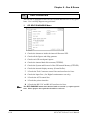
5.2
Initialization Items
The contents of the Initialize setup items listed below are explained in this
chapter. To learn about screen operations and numeric input
Reference Chapter 4, "OFFLINE Mode"
5-2
1
SYSTEM ENVIRONMENT SETUP
System Settings
System Area Settings
Global Window Settings
Character String Data Settings
2
SET UP I/O
Set Up SIO
Set Up Printer
Set Up Touch Panel
Communication Setup
3
PLC SETUP 1:1
Set Up Operation Surroundings
3
PLC SETUP n:1
Set Up Operation Surroundings
Station Setup
Customize Setup
4
INITIALIZE MEMORY
5
SET UP TIME
6
SET UP SCREEN
GP-470/570 Series User's Manual
Chapter 5 - Initializing the GP
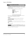
5.3
SYSTEM ENVIRONMENT SETUP
GP environment adjustments are made here. The SYSTEM ENVIRONMENT
SETUP includes the SYSTEM SETUP, SYSTEM DATA AREA, GLOBAL WINDOW
SETUP, and CHARACTER STRING DATA SETUP.
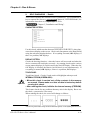
1. SYSTEM SETUP
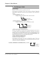
STAND-BY MODE TIME (0-255)
To protect the GP display screen, GP has been setup with a screen saver function that automatically erases the screen when no GP operations have occurred
for the time entered here. A 0 entered in this field causes a normal display.
When SYSTEM DATA AREA's ( Reference PLC Connection Manual)
SCREEN DISPLAY OFF*1 data is 0000h, and the following operations are not
performed on the screen for the number of minutes setup, the GP display erases.
• Change Screen
• Touch Screen
• Alarm Display
START TIME (0-255)
This setup determines the start-up time of the GP. Use this setup to adjust the
power up sequence so that the GP starts up after the PLC.
TOUCH BUZZER SOUND
Setup whether or not the GP beeps when pressed.
BUZZER TERMINAL OUTPUT
Setup whether or not the BUZZ signal is output from GP's AUX I/F. This
option is for an external buzzer.
PASSWORD SETUP(0-9999)
The password setting is used when changing to the Initialize Memory or
Initialize (OFF-line mode) Screens. The password (number) ensures protection of the GP setups as OFF-line mode will not be entered inadvertently.
Enter the optional number of your choice. If you do not wish to use this setup,
enter the default 0.
*1 When using the Direct Access or the Memory Link formats, the object address becomes
+9 or +12, respectively.
GP-470/570 Series User's Manual
5-3
Chapter 5 - Initializing the GP
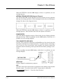
DATA TYPE OF SCREEN NO.
This setup controls whether BIN or BCD format numbers are used when making
screen changes. Screen numbers 1~8999 are available when set up in binary
format; screen numbers 1~1999 are available when set up in BCD format.
2. SYSTEM AREA SETUP
SYSTEM AREA SETUP data is necessary for the PLC to control the GP, and
prepare the PLC internal Data Memory (DM) and Data Register (D)*1. Use
this area to prepare the desired SYSTEM DATA AREA items. When using
Memory Link format, however, this setting is unnecessary.
Reference
PLC Connection Manual
Press the item number—when the item is highlighted, it has been selected.
System Area Size
This field displays the total number of words of the items selected from the
SYSTEM AREA SETUP (Write 1 to 5 and Read 6 to D).
When you press the Confirm key, the SYSTEM AREA CONTENTS screen appears to ratify the selected items
Note:
• The setup shown is efficient only when using the Direct Access format.
• The selected System Area items, as displayed on the screen, become the System
Data Area.
When these five items, "Current Screen Number", "Error Status", "Clock Data
(Current)", "Change Screen Number", and "Display ON/OFF", have been
selected, word addresses are assigned to each item, in order, as shown on
the next page.
*1 Data Memory (DM) refers to OMRON Co.'s PLC ; Data Register (D) refers to Mitsubishi
Electric Co.'s PLC.
5-4
GP-470/570 Series User's Manual
Chapter 5 - Initializing the GP
!
Important
Addresses LS16 to LS19
are fixed since they control
the Global Window. These
addresses cannot be used
for any other purpose.
The System DataArea selection process follows this formula [System Data
Start Address + n]. For example, if the System Area Start Address was D00200,
and the Change Screen Number option had been selected—if you refer to the
System Area Contents screen displayed above—because Change Screen
Number's address is pegged at +6, its word address would be
D00200+6=D00206. For more information on the LS Area 16~19
Reference Software PLC Connection Manual,1.1.2 "LS Area Structure"
3. GLOBAL WINDOW SETUP
The GP unit can display one Global Window and two Local Windows at any
one time. The Global Window is common to all the display screens. The
Local Window displays exclusively on the corresponding base screen. The
GLOBAL WINDOW SETUP is described here.
GLOBAL WINDOW
There are two options here: Use and Do Not Use. If you select Do Not Use,
ignore the items described below. Selecting Use makes these options available.
GLOBAL WINDOW ACCESS
Setup the Global REGISTRATION NO. and the WINDOW LOCATION as Direct
or Indirect values. When set as Direct, the REGISTRATION NO. and WINDOW
LOCATION selections are fixed to the values setup here. When set to Indirect,
the WINDOW REG. NO. word address, as prepared in the System Area, is
variable—which means it can have the REGISTRATION NO. written to it—and
GP-470/570 Series User's Manual
5-5
Chapter 5 - Initializing the GP
as a result, multiple window screens can be used as Global windows. Using
this same method, adjust the Global window position, by writing the X,Y coordinates to the SYSTEM AREA's WINDOW LOCATION word addresses.
DATA FORMAT
Setup whether the REGISTRATION NO. and the WINDOW LOCATION values are
inputted as BIN or BCD numbers. This field affects only direct values..
REGISTRATION NO. (1-256)
Setup the Window Screen Number used by the Global Window. This field is
applicable only when the GLOBAL WINDOW ACCESS is set to Indirect.
WINDOW LOCATION
Setup for the Global WINDOW LOCATION. This field is applicable only when
the GLOBAL WINDOW ACCESS is set to Indirect.
4. CHARACTER STRING DATA SETUP
Character String Data ordering varies from manufacturer to manufacturer.
Setup the Character String Data order here to match the corresponding PLC.
Setup the CHARACTER STRING DATA MODE to match the PLC
type. Device type and Tag settings are unavailable.
Important
!
Find the data storage order for your PLC in the table, next page, and setup the
CHARACTER STRING DATA MODE.
(I) Data Device Storage Order
(II) Internal Word Byte LH/HL Storage Order
(III) Internal Double-word Word LH/HL Storage Order
5-6
GP-470/570 Series User's Manual
Chapter 5 - Initializing the GP
CHARACTER STRING DATA MODE List
I) Data
Device
Storage
Order
II) Internal
Word, Byte
LH/HL
Storage Order
Storage
from Start
data
LH order
III) Double-word Character
Internal Word
String
LH/HL Storage
Data Mode
Order
HL order
Storage
from End
Data
LH order
HL order
LH order
4
HL order
2
LH order
5
HL order
1
LH order
6
HL order
7
LH order
8
HL order
3
I)
Data Device Storage Order
E.g. Characters
ABCDEFGH
! $
• Storage from Start Data
& (
!
D100
(
D100
$
D101
&
D101
&
D102
$
D102
!
D103
(
D103
II) Word Byte LH/HL Order
E.g. Characters
ABCD
!$&(
• 16 bit Device LH Order
• 16 bit Device HL Order
$
!
D100
!
$
D100
(
&
D101
&
(
D101
• 32 bit Device LH Order
$
• Storage from End Data
!
GP-470/570 Series User's Manual
(
&
• 32 bit Device HL Order
D100
!
$
&
(
D100
5-7
Chapter 5 - Initializing the GP
III) Double-word Word LH/HL Order
E.g. Characters "A B C D E F G H I J"
! $ & ( "
• 16 bit Device HL Order
• 16 bit Device LH Order
E.g.
$
D100
!
D100
!
D101
$
D101
(
D102
&
D102
&
D103
(
D103
"
D104
"
D104
Characters "A B C D E F G H I J K L M N O P Q R S T"
! $ & ( " % ' # * )
• 32 bit Device LH Order
• 32 bit Device HL Order
$
!
D100
!
$
D100
(
&
D101
&
(
D101
%
"
D102
"
%
D102
#
'
D103
'
#
D103
)
*
D104
*
)
D104
Relationship between K-tag Write Character Value and PLC Device
• 16 bit Devices
GP stores the character string from the start, as groups of 2, into1 PLC Device.
When there are nine characters, they are arranged as shown below.
1 2 3 4 5 6 7 8 9 "
Note:
When the characters do not divide into 2 evenly, NULL is added at the end.
• 32 bit Devices
GP stores the character string from the start, as groups of 4, into1 PLC Device.
When there are nine characters, they are arranged as shown below.
1 2 3 4 5 6 7 8 9 "
Note: When the characters do not divide into 4 evenly, NULL is added.
5-8
GP-470/570 Series User's Manual
Chapter 5 - Initializing the GP
5.4
SET UP I/O
This section describes the communication setup with the host PLC and the setup
for any peripheral equipment. The SET UP I/O menu includes the SET UP SIO, SET
UP PRINTER, SET UP TOUCH PANEL, and COMMUNICATION SETUP menus.
1. SET UP SIO
This menu runs the setups related to PLC communication. Match the settings
listed below with the SIO setup on the PLC host side.
Reference PLC Connection Manual 2 -*- 4/5 -*- 4 (Environment Setup Data)
COMMUNICATION RATE
The COMMUNICATION RATE (baud rate) is the data communication speed, measured in bits per second (bps), between the GP and PLC. Match the COMMUNICATION RATE values in both the PLC and GP.
DATA LENGTH
For data communications, the DATA LENGTH must be set up as 7-bit or 8-bit data.
STOP BIT
Set up the STOP BIT as either a 1-bit or 2-bit value.
PARITY
Set up whether no parity check, or an odd or even number parity check will take
place during communication.
CONTROL
Data flow CONTROL prevents the overflow of data sent back and forth. Select
either X-CNTRL or ER-CNTRL.
GP-470/570 Series User's Manual
5-9
Chapter 5 - Initializing the GP
COMMUNICATION FORMAT
Select one of the following options for the communication format: RS-232C,
RS-422 (4 line), or RS-422 (2 line).
!
Important
When communicating with the Memory Link format using RS-422,
select the 4-line option.
2. SET UP PRINTER
PRINTER TYPE
Designates the type of printer used with the GP unit.
Use the EPSON ESC/P settings for 24 dot printers, and the HP-LaserJet Series
option for PCL4 compatible printers.
PRINT (GP-570 and GP-571 Series units only)
Setup whether the printer outputs in Monochrome or Color.
Each of these pairs, Blue and Green, Cyan and Red, and Purple and Yellow,
appears with the same pattern when output in monochrome.
!
Important
The HP-LaserJet Series does not support GP color printouts. With
these printers, always use the GRAY SCALING selection.
BLACK/WHITE REVERSE (GP-570 and GP-571 Series)
This setup reverses the screen colors from white on black (Fg/Bg) to black on
white for screen printouts. The screen background on the GP is black, but it is
easier to see screen objects on the hardcopy when Reverse is ON so the screen
prints white.
E.g.
When the GP screen background is black and the foreground is
white, the printout appears as follows.
Print w/ Reverse ON
5-10
Print w/ Reverse OFF
GP-470/570 Series User's Manual
Chapter 5 - Initializing the GP
The previous setup is only for printing the screen image.
When an Alarm has been set OFF, no matter what this setting is, it
Important will print as if REVERSE is ON.
!
3. SET UP TOUCH PANEL
Touch operation and Force Reset setup, and Display Device adjustments are
made here.
TOUCH OPERATION MODE
Set up either One Point or Two Point input.
FORCE RESET
Set up whether or not a FORCE RESET operation is in effect.
Steps to run FORCE RESET
While holding down the bottom right corner (1) of the screen, press the upper
right corner (2). At the same time, press the bottom left corner (3) to enter the
FORCE RESET Operation. To activate Reset, press the RESET button, to transfer to OFF-line Mode, press OFFLINE.
!
• FORCE RESET occurs even during RUN mode and OFF-line mode.
Important
GP-470/570 Series User's Manual
5-11
Chapter 5 - Initializing the GP
Note: • The FORCE RESET mode cannot be entered while waiting for the GP to start up.
• Entering FORCE RESET is possible even when RUN operations (PLC <—>GP communication) do not occur.
CONTRAST ADJUSTMENT (Only for GP570-SC**)
When this option is set ON, CONTRAST ADJUSTMENTs can be made through
touch input.
While pressing the upper right hand corner (1) of the screen, press the upper
left corner (2) to enter CONTRAST ADJUSTMENT mode. Press the desired setting
and the screen's contrast will change accordingly.
Note:
• To exit CONTRAST ADJUSTMENT mode, press anywhere outside the
contrast option bar.
• CONTRAST ADJUSTMENT mode cannot be entered while waiting for GP
to start up.
• CONTRAST ADJUSTMENTs can be made even in the middle of RUN mode
(PLC<—>GP communication).
BRIGHTNESS ADJUSTMENT (Only for GP-470 Series)
When set ON, BRIGHTNESS ADJUSTMENTs can be accomplished through touch
input.
Press the bottom left corner (2) of the screen while holding down the bottom
right corner (1) to enter BRIGHTNESS ADJUSTMENT mode. Touch the left-side
of the bar to brighten the display; touch the right-side of the bar to dim the
display.
5-12
GP-470/570 Series User's Manual
Chapter 5 - Initializing the GP
Note:
• To end BRIGHTNESS ADJUSTMENT mode, press anywhere outside the bottom
of the screen.
• BRIGHTNESS ADJUSTMENT mode cannot be entered while waiting for GP to
start up.
• BRIGHTNESS ADJUSTMENTs can be made even during RUN mode (PLC<—
>GP communication).
4. COMMUNICATION SETUP
These fields set when an error message is reported after a GP<—>PLC communication error is detected. This ensures an error has actually taken place
and not just slight breaks in communication or slowness in processing data on
one side or the other.
RECEIVE TIMEOUT
Set up how long the GP unit will wait when there is nothing being sent to it.
(This is the Timeout Time.) However, if there is no cable connected up, then
regardless of the time set up here, the Timeout value is 1 second. The default
value is 10 seconds.
Note:
When a value of over 30 seconds is set here, and a screen is transferred from the
PC while a PLC Communication Time error has occurred, an error may also
appear on the PC side.
RETRY COUNT
Set up the number of times the GP will try to send data when a Communication
error occurs. Even if the data is resent, unless the transfer is successful, an
error message will be displayed on the GP. The default value is 2 times.
GP-470/570 Series User's Manual
5-13
Chapter 5 - Initializing the GP
5.5
PLC SETUP
Setup the System Area and the Unit number in this screen. Because 1:1 and
n:1 GP connections change the setup contents, check it before running any
setups.
Note:
With the GP-PRO/PBIII for Windows “Simulation” feature, the GP’s “Setup
Operation Surroundings” area cannot be used.
1. SET UP OPERATION SURROUNDINGS (1:1)
Setup the PLC System Data Area and the Unit Number here.
Note:
This setup is only necessary when using the Direct Access format.
STARTING ADDRESS OF SYSTEM DATA AREA
Setup the PLC's Data Register (D), Data Memory (DM), etc. allotted by the
STARTING ADDRESS OF SYSTEM DATA AREA.
UNIT NO.
Set up the PLC UNIT number here. Make sure it matches the one set up in the
PLC.
!
Important
Note:
5-14
SYSTEM AREA—READING AREA SIZE (0-256)
When using a Block Display Trend Graph, setup the Reading Area Size (in
word units) to match the Trend Graph's data size. Setup when you wish to
allocate the Reading Area in the PLC Data Register (D), or Data Memory
(DM).
• If you are not using the Reading Area, leave the 0 default values
intact. High Speed Communications can be secured as a result.
• When using Hitachi's HIDIC-S10 a Series, an extra item titled
"Extended Memory Address (HIDIC) [000000]" is added to the
above screen display. Values accepted by the extended memory
start address are 0 (memory not extended), and 100000~1FF000.
• When using Matsushita Electric's NEWNET-FP, an extra item titled "Monitor Register" is added to the screen display. If using 2 or more CCU's
(communication unit) as in the following diagram, and a GP is connected to
each CCU, select 1:1 connection and setup the Monitor Register as "None".
GP-470/570 Series User's Manual
Chapter 5 - Initializing the GP
Matsushita Newnet FP
Note: • When connecting only one GP (to a PLC), be sure to see the Monitor Register
to ON.
2. SET UP OPERATION SURROUNDINGS (n:1)
This is the setup for the PLC System Data Area and the Unit Number for an
n:1 (multi-link) PLC connection.
For more about the SYSTEM DATA AREA with the n:1 (multi-link) connection,
Reference PLC Connection Manual
Note: This setup is only necessary when using the Direct Access format.
STARTING ADDRESS OF SYSTEM DATA AREA
Setup the PLC's Data Register (D), Data Memory (DM), etc. allotted by the
STARTING ADDRESS OF SYSTEM DATA AREA.
UNIT NO.
Set up the PLC UNIT number here. Make sure it matches the one set up in the
PLC.
SYSTEM AREA—READING AREA SIZE (0-256)
When using a Block Display Trend Graph, setup the Reading Area Size (in
word units) to match the Trend Graph's data size. Setup when you wish to
allocate the Reading Area in the PLC Data Register (D), or Data Memory
(DM).
• If you are not using the Reading Area, leave the 0 default values
!
Important
unchanged. This will allow High Speed data transmission to be
performed.
GP-470/570 Series User's Manual
5-15
Chapter 5 - Initializing the GP
3. STATION SETUP (n:1)
The STATION SETUP, necessary for the n:1 (multi-link) setup, checks whether
correct communications run with the connected GP System configuration.
NETWORK INFORMATION ADDRESS
In the n:1 (multi-link) connection, the Network Information uses 2 words in its
correspondences. These two (2) words consist of a Connection List and a
Validation List (described later in this section). These areas are allocated in
the PLC's Data Register (D) or Data Memory (DM).
PLC Data Register
In the NETWORK INFORMATION ADDRESS, setup the same
address to all the GP's connected to the same link unit. Also,
!
Important when there are 2 ports in the connected link unit, do not make
them the same address.
• Connection List
The word address for the Connection List sets up the number of GP's connected to the PLC, which must be registered beforehand on the PLC side.
When these GP's are connected to the PLC, the corresponding PLC bit numbers
for the particular GP Stations (see below) turn ON.
Note:
When the GP is connected to the PLC, and the option of GP only correspondence ends and Offline mode is entered, the GP Station Number turns the corresponding PLC bit OFF.
Bit 15
5-16
Bit 0
GP-470/570 Series User's Manual
Chapter 5 - Initializing the GP
For example, when these 4 GP units—bit 0, bit 2, bit 3, bit 5—are connected,
002D (h) is written here.
Connection List
!
Important
0 0 0 0 0 0 0 0 0 0 1 0 1 1 0 1 002D (h)
• Be certain to enter these settings before running the GP.
• Turn all bits not connected to the GP OFF.
• Verification List
This area responds to the correspondence from each connected GP. In the
Verification List, when the same bit numbers as the Connection List turn ON,
data communication can be performed. Next, the Station Numbers of the
communicating GPs turn their corresponding PLC bit numbers ON.
Bit 0
Bit 15
If the settings used for the GP and PLC agree, the Connection List values are
written to the Verification List.
For example, the value 002D (h) in the Connection List, setup here as the 0
bit, 2 bit, 3 bit, and 5 bit, will then be written to the Verification List.
Connection List
0 0 0 0 0 0 0 0 0 0 1 0 1 1 0 1 002D (h)
Verification List
0 0 0 0 0 0 0 0 0 0 1 0 1 1 0 1 002D (h)
!
Important
• When the Connection List and Verification List settings do not
match, a COMMUNICATION ERROR will occur.
• When changing the connected devices, first turn all the bits OFF.
• Even if the GP is connected, if the Connection List data is turned
OFF, data transfer cannot occur, and an error will not display.
STATION NO.
This is the setting for the GP Station Number mentioned above. The setup
range is from 0 to 15, and the only restriction is that the GP STATION NO.s
used must be unique in the system. If STATION NO.'s are repeated, a COMMUNICATION ERROR occurs.
Note: • The STATION NO. is the unique number allocated to each GP used. This
number is not related to the Link Unit Machine number.
GP-470/570 Series User's Manual
5-17
Chapter 5 - Initializing the GP
4. CUSTOMIZE SETUP
The Customize function adjusts the n:1 (multi-link) communication method
to make it more effective. For data transfer to be performed efficiently, designate
either Operation or Display priority on your GP. This setting can help to improve
your GP's communication response speed.
PLC PRIORITY
According to how the GP is used, select either Operation priority (OPE.) or
Display priority.
• Display
Setup the GP to this option when using the GP mainly as a monitor screen.
The GP will command a higher display speed as a result; however, the response
time for the touch panel's operations will slow.
• Operation
Setup the GP to this option when using the GP mainly as an operation panel.
As a result, the GP will command better touch panel numeric input and switch
response times.
Leaving the GP in this mode does not influence the touch panel operation
response time of the rest of the GP's very much; however, the screen display
refresh cycle will slow down
• The standard arrangement uses the same settings with all connected GP's.
Note: • To increase the display speed, restrict the address setup to consecutive addresses
wherever possible. And make bit addresses consecutive to the word unit.
• Speed Difference between Display Priority and Operation Priority
When using the Mitsubishi Electric Corp. A3A PLC, with a scan time of 20ms
and consecutive addresses (80 words not included in the System Area), the
difference in reading speed is as shown in the following graphs.
5-18
GP-470/570 Series User's Manual
Chapter 5 - Initializing the GP
GP TOUCH MONOPOLIZE
The monopolizing of touch panel use can be set ON or OFF. When you want
to use the PLC exclusively (
Reference PLC Connection Manual)
with a Momentary operation setup on the touch panel, turn GP TOUCH MONOPOLIZE ON.
When this setup is ON, the touch panel uses the PLC exclusively whenever
the momentary operation setup on the panel is pressed. In this way, you can
use the inching operation with a momentary switch. When you stop pressing
the panel, exclusive use ends.
MONOPOLIZE TIME (0 to 2550s)
This field controls the length of time for the monopolize process when no
other touch panel operations are performed. The Monopolize process begins
when the System Data Area's 7th bit of word address LS14 turns ON, and ends
either when the bit turns OFF, or when the time set here passes.
Note:
• Pressing the touch panel in the middle of the monopolize process interrupts the MONOPOLIZE TIME function, ending exclusive use.
• When MONOPOLIZE TIME is set to 0, the monopolize function does not
end automatically.
For more about the contents of System Data Area LS6 (status) and LS14 (control)
Reference
PLC Connection Manual
GP-470/570 Series User's Manual
5-19
Chapter 5 - Initializing the GP
5.6
INITIALIZE INTERNAL MEMORY
This command erases all the GP screen data.
!
• You cannot cancel the Initialization procedure after pressing the
Start key.
Important
• When modifying the initial setting data of a GP with backup SRAM
built in, all data backed up to that point will be saved if the GP's
system version is 1.30 or later. (GP-PRO/PBIII for Windows 95
version 2.0 or later) With earlier GP system versions, all data
will be lost.
• Initialization does not erase the SYSTEM SET UP, the SIO protocol,
or the internal clock settings.
****KB + SRAM
If the word
"SRAM" is
displayed, the GP
has SRAM built-in
To initialize the GP internal memory, enter the common password 1101, or the
password entered in the SYSTEM SET UP screen.
Reference Chapter 4, "Input Number"
Note:
The time required for Initialization is between 10 and 20 seconds.
5.7
SET UP TIME
Set up the GP's internal clock.
TIME SET UP
Enter date and time corrections to the date and time displayed in the PRESENT
TIME.
24 hour clock
last 2 digits of
year are displayed
5-20
GP-470/570 Series User's Manual
Chapter 5 - Initializing the GP
Note:
The time displayed on the screen using the Time Display function is not 100%
accurate. At room temperature, the GP internal clock has an accuracy of +/- 65
seconds/month. The surrounding temperature and age of the unit can decrease
its accuracy up to +90 to -380 seconds/month. However, the screen Time display
is in minute intervals, so this error may not be a factor.
5.8
SET UP SCREEN
The initial screen display upon powering up, the character size when in RUN
mode, and other related items are setup here.
INITIAL SCREEN NO.
Set up the screen file number that will display first upon powering up. If the
BIN option for DATA TYPE OF SCREEN NO in SYSTEM SET UP had been selected, enter a number between 1~8999. Or, if BCD was the option set up,
then input a number between 1~1999.
ALARM MESSAGE
Set up the character size of the ALARM MESSAGE when the Alarm Bulletin is
activated.
1
Height=1; Width=1
16×8 pixels
2
Height=2; Width=2
32×16 pixels
4
Height=4; Width=4
64×32 pixels
ONLINE ERROR DISPLAY
Set up whether or not error messages display during RUN mode.
FONT SETTING
Select the character font that displays during RUN mode.
GP-470/570 Series User's Manual
5-21
Chapter 5 - Initializing the GP
KANJI FONT QUALITY
◆When [FONT SETTING] is set to [JAPAN]
Full sized characters:
[STANDARD] : Full sized 16-dot characters display. When enlarged,
this font will remain a 16-dot character. (Compatible
with GP-*30 series units.)
[HIGH]:
Any character which is Level 1 JIS Kanji Code standard
larger than 2 x 2 will display as a 32-dot character.
Level 2 JIS Kanji Code standard characters, no matter
what the current font setting is, will always display
using 16 dots.(Compatible with GP-*50 and GP-*70 se
ries units.)
[1,2]:
Level 1 or 2 JIS Kanji Code standard characters that are
larger than 2 x 2, will display as 32-dot characters.
◆When [FONT SETTING] is set to any other type
A full sized character (except Alphabets) is displayed with 16-dot font, even
when it is displayed with an enlarged size. Half sized characters are displayed as:
[STANDARD] : Half sized 16-dot characters display. When enlarged,
this font will stay as 16-dot character. (Compatible with
GP-*30 series units.)
[HIGH]:
Alphabets and numerals (exceptions not included) will
display as high quality font-character.
[1,2]:
Alphabets and numerals (exceptions not included) will
display as high quality font-character.
The [HIGH] selection is factory set.
5-22
GP-470/570 Series User's Manual
Chapter 6
GP RUN and Errors
1. RUN Mode
2. Troubleshooting
3. SELF-DIAGNOSIS
This chapter describes the GP RUN mode and problem solving processes.
6.1
RUN Mode
There are two ways of entering RUN mode, from powering up and from
OFFLINE mode.
1. After Powering Up the GP
First, connect the GP power cable. After the unit has powered up, the START
TIME value—set up in INITIALIZE/ SYSTEM SET UP—determines how long the
display, illustrated below, appears, until it gives way to the screen number
setup in the INITIALIZE/ SET UP SCREEN menu. However, if a screen has not
been designated, or if the screen set up does not exist, then the display below
will remain.
2. Via OFFLINE Mode
Press the OFFLINE mode MAIN MENU item number 4, RUN. The INITIALIZE/
SET UP SCREEN option determines the first screen that appears in RUN mode,
thereby beginning communication with the PLC. However, if a screen has not
been set up, or if the screen set up does not exist, then the display above remains.
GP-470/570 Series User's Manual
6-1
Chapter 6 - Run & Errors
Note:
• To enter OFFLINE Mode, simply touch the top left corner of the GP's
screen within 10 seconds after connecting the GP's power cord.
E.g. After powering up the GP, the initial screen that appears is equipped
with a built-in (invisible) switch in the top left corner. Touch this switch to
change the GP from RUN to OFFLINE mode.
The user can, if desired, create and place a switch-like object ("Go to Main Menu", for
example) in their first screen's top left corner to help them to remember this feature)
6.2
Troubleshooting
This section describes how to find and resolve problems that may occur on the
GP. If there is a problem on the PLC side, refer to the corresponding PLC
manual.
1. Possible Types of Trouble
Shown below are some problems that may occur while using this unit.
No Display
The screen will not display even when the unit is powered On. Also,
during RUN mode, the screen disappears.
No GP/Host Communication
The GP unit cannot extract data from the host. An error message may
appear on the screen as a result. For more about error messages, refer to
the section in this chapter titled, "Error Messages".
Touch Panel Does Not Respond
The touch panel does not react when pressed, or the reaction time is very
slow.
OFFLINE displays During RUN Mode
For the first three problems, see the flowcharts listed on the following pages.
For the last problem, a SYSTEM ERROR may have developed while displaying
the OFFLINE mode screen.
Reference Chapter 6-4-2 Error Message Details
6-2
GP-470/570 Series User's Manual
Chapter 6 - Run & Errors
!
GP Operation Cautions:
Warning
• To prevent an electric shock, confirm that the GP's
power cord is not plugged in to the main power before attaching the cord's power terminals to the GP.
• Be sure to use gloves when changing the backlight,
since there is the possiblity of receiving an electric
shock or being burned.
Note:
• The following section assumes that the GP is the cause of any problems,
not the host. When the host (PLC) is the problem, refer to that maker's
corresponding PLC manual.
GP-470/570 Series User's Manual
6-3
Chapter 6 - Run & Errors
2.
No Display
Follow the flowchart below when the screen does not display when powering
up, or the screen turns OFF by itself during RUN mode, to find an appropriate
solution.
No Screen Display
Has data transferred
from the Screen
editor?
NO
Transfer screen data from the screen
editing software.
Reference
Chapter 4.5, "Transfer Screen Data".
YES
YES
Does the power lamp
turn On?
NO
Is it using the correct
power voltage?
NO Plug in the power cable properly.
Reference Chapter 2, "Specifications".
YES
Unplug the GP's power cord.
Disconnect the SIO and AUX cable.
Is the power cable connected
properly to this unit?
NO Fix the power cable connection.
Reference Chapter 3, "Installation and Wiring".
YES
Does turning on the
power cause a display?
YES
Turn Off the power and reconnect
the SIO cable, or the AUX cable.
NO
6-4
GP-470/570 Series User's Manual
Chapter 6 - Run & Errors
Again, does turning the
power ON cause a display?
YES
Complete
NO
Only for
GP-470
Is the SIO cable, AUX
cable connected properly to
this unit?
Only for
GP-570
YES
NO
YES
Connect the cable properly.
Reference Chapter 3, "Installation
and Wiring" & PLC Connection Manual.
Does the backlight (CFL)
light up?
Possible problems with the
PLC. Check if the PLC is
working properly.
NO
Has the backlight (CFL)
been setup correctly?
YES
Go to OFFLINE mode.*1
(Press the upper left corner of the screen)
NO
NO
Correctly setup the backlight (CFL) in
Reference "Changing
the GP.
the Backlight".
(See next page,
bottom)
Does the OFFLINE
menu display?
YES
See if INITIALIZE/ SET UP
SCREEN is OK.
NO
Set up the correct Screen file
number.
Reference
Chapter 5, "Initialize".
YES
GP-470/570 Series User's Manual
6-5
Chapter 6 - Run & Errors
Has Off data been written
to the SYSTEM DATA
AREA?
NO
NO
Run SELF-DIAGNOSIS'
INTERNAL FEPROM
CHECK*2. Is it OK?
YES
Erase the data that has been written. When using Direct Access, the
address is +9; when using Memory
Link, the address is +12. For more
on the SYSTEM DATA AREA
Reference PLC Connection
Manual.
Internal FEPROM Data has altered.
Initialize FEPROM, transfer the
data, and try using again.
NO
There is a problem with the GP
unit. Please contact your local
GP distributor.
From
(from previous page) *1 To make the OFFLINE screen appear, turn the power Off, then back On, and press the upper
left corner of the screen within 10 seconds.
*2 When you run the FEPROM CHECK in SELF-DIAGNOSIS, all the screen data gets erased. Be
sure to make a backup of all the screens.
6-6
GP-470/570 Series User's Manual
Chapter 6 - Run & Errors
3. No GP/Host Communication
When the GP will not communicate with the host PLC, follow the flowchart
below to find both the cause of the problem and a suitable response.
Or, if an error message displays on the screen, check the error code (refer to
the Error Message section in this chapter) to find the appropriate solution.
Does not communicate
Unplug the GP's power cord
Has the correct PLC
protocol (Table file)
been selected?
NO Setup the protocol that corresponds
with the connected PLC.
Reference Operation Manual
YES
Is the SIO cable attached properly to this
unit?
Attach the SIO cable unit properly,
NO making sure all connections are
secure. Reference PLC Connection Manual
YES
Is the AUX cable
attached properly?
YES
Is the Termination
Resistor setup correctly?
YES
Disconnect all the cables except the
power cable and turn the unit On.
GP-470/570 Series User's Manual
Attach the AUX cable unit properly,
making sure all connections are seNO
cure. Reference Chapter 3,
"Installation and Wiring".
Setup the Termination Resistor in the
correct position with the correct values.
NO Resistor position and values change
with each PLC type. When using
the Direct Access format,
Reference PLC Connection
Manual.
For RS-422, use the solutions provided
in the dotted rectangle, above.
6-7
Chapter 6 - Run & Errors
Is the SELF-DIAGNOSIS/
SIO CHECK OK?
NO
YES
Are the corresponding
SIO INITIALIZE settings
OK?
YES
Enter correct settings
and values.
Reference Chapter
5, "Initialize".
Is the Tag setup
correct?
YES
NO
NO
Check the tag data, and
correct the setup values.
Reference Tag
Reference Manual.
There is a problem with the GP
unit. Please contact your local
GP distributor.
Possible problems with the
PLC. Check if the PLC is
working properly.
Note:
6-8
• To run SELF-DIAGNOSIS options RS-232C Check/ RS-422 Check, special tools
become necessary.
Reference SELF-DIAGNOSIS section in this chapter
GP-470/570 Series User's Manual
Chapter 6 - Run & Errors
4. Touch Panel Does Not Respond
When the touch panel does not respond, or its response time is very slow after
it is pressed, please use the flowchart below to find the origin of the problem,
and the appropriate solution.
Touch panel not responding
In the INITIALIZE/ SET UP TOUCH
PANEL option, enter values applicable to the Touch Operation Mode.
Reference Chapter 5, "Initialize"
Is INITIALIZE's SET
UP TOUCH PANEL
correct?
YES
Disconnect all the cables (including SIO cable and AUX
cable), except the Power cable.
Run SELF-DIAGNOSIS/
TOUCH PANEL CHECK to
see the GP is OK
NO
YES
Are the settings for
touch input tags, or for
Parts correct?
NO
YES Set the addresses
within the allowable range,or redefine the touch area.
There is a problem with the GP
unit. Please contact your local
GP distributor.
GP-470/570 Series User's Manual
6-9
Chapter 6 - Run & Errors
6.3
SELF-DIAGNOSIS
The GP unit is equipped to check its own System and Interface for any problems. Use it to help diagnose any problems.
1.
GP SELF-DIAGNOSIS Menu
1
Checks the characters inside the internal Character ROM.
2
Checks all the figures and tiling patterns.
3
Checks each GP touch panel square.
4
Checks the internal hard disk contents (FEPROM).
5
Checks the System and Protocol of the GP Internal Memory (FEPROM).
6
Checks the internal display memory (Frame Buffer).
7 *Checks the Tool Connector control lines and send/receive lines.
8
Checks the Input Port. (for Digital's maintenance use only)
9
*Checks the AUX control line.
A *Checks the printer interface.
B *Checks the RS-232C and RS-422 send/receive lines.
Note:
6-10
The SELF-DIAGNOSIS menu items marked with an asterisk (*) require special
tools. Please prepare the required tool/cable for each test.
GP-470/570 Series User's Manual
Chapter 6 - Run & Errors
2.
SELF-DIAGNOSIS - Details
This section explains the contents of SELF-DIAGNOSIS. For information on
Reference Chapter 4, "OFFLINE Mode"; for
how to operate the Screen,
information about how to set up the Special Tools,
Reference Chapter 3, "Installation and Wiring".
CHARACTER PATTERN
Use this check, which runs the character ROM CHECK-SUM CHECK, when characters do not display on the screen. Check each font pattern or the Kanji ROM
using the sub-menu displayed above. If everything is normal, OK displays; if
there is a problem, NG displays.
DISPLAY PATTERN
Checks the drawing function—when the buzzer will not sound and when the
device contents will not display correctly—by running checks on the various
screen pattern displays (8 screens) and on the On/Off Display. When the On/
Off Display is checked, the Buzzer On/Off check is run simultaneously. If
everything is normal, OK displays; if there is a problem, NG displays.
TOUCH PANEL
Touch Panel check. Checks if each touch cell highlights when pressed.
INTERNAL FEPROM (SCREEN AREA)
• When this check is carried out, all the contents in the memory
are erased. Please make sure that all data is backed up before
Important
running this check.
• After running the check, initialize the internal memory (FEPROM).
!
This feature checks for any problems that may arise in the display. But to run
the check, a password*1 is necessary.
When running the check, the screen will change as follows.
*1 Enter the password as setup in the INITIALIZE option, or the default password 1101.
GP-470/570 Series User's Manual
6-11
Chapter 6 - Run & Errors
When the FEPROM is normal, OK displays; if there is a problem, an error
message appears.
INTERNAL FEPROM CHECKSUM (System & Protocol)
The Internal FEPROM System and Protocol check searches for any problems
that may arise during operations. When running the check, the screen undergoes
changes like those in the diagrams below.
When the FEPROM is normal, OK displays; if there is a problem, an error
message appears. This check does not erase the System or Protocol.
FRAME BUFFER
The Frame Buffer (display memory) Check looks for any display problems
that may develop. When everything is normal, OK displays; when there is a
problem, an error message displays.
TOOL CONNECTOR LOOP BACK
Use the Tool Connector Control line and Send/Receive line check when the
GP cannot send and receive data from the PC. To run the check, connecting a
Tool Connector Check Loop Back Cable (Dsub25 pin female connection)
mounted to the Downloading Cable (provided in the software package) is necessary.
When everything is normal, OK displays; when there is a problem, an error
message displays.
INPUT PORT
Used by Digital for maintenance purposes.
AUX
The AUX Control line check looks for problems in the Inching output and the
Monitor output. To run the check, the PLC input must be connected.
Reference Chapter 2.3, "Interface Specifications"
6-12
GP-470/570 Series User's Manual
Chapter 6 - Run & Errors
This check works by using the Input unit's LED lighting, following the steps
below.
!
$
&
Set AUX lines from TSW0 to BUZZ, ON.
Once all of them turn ON, they will turn OFF in the same order.
Once all of them have turned OFF, the check is finished.
PRINTER I/F
PRINTER I/F checks to see if the printer operates normally. This check necessitates the connection of the printer.
When a Print Buffer is used, sometimes an error occurs, so connect the printer
directly to the GP.
If normal, the printed section displays 20~7D<HEX> and A0~DF<HEX> and
OK; if there are problems, an error message appears.
SIO CHECK
Checks the RS-232C and RS-422 SIO lines for areas where correspondence
problems develop. In the menu, select which check to run. To run the check,
connecting the SIO cable is necessary. If all is normal, OK displays; if there is
a problem, an error message appears.
The SIO cable wiring is as shown below. (RS-232C, RS-422 common)
GP-470/570 Series User's Manual
6-13
Chapter 6 - Run & Errors
6.4
Error Messages
This section explains the messages that appear when an error has occurred in
the GP unit during RUN mode. The origin of the problem behind each error
message is explained with appropriate ways of disposing of the error.
After a problem has been solved, unplug the GP's power cable and then reattach
it.
1.
Error Message List
The error messages listed below appear on the GP unit. Instructions on how to
find and solve problems causing these error messages are explained on the
following pages.
• SYSTEM ERROR
• ILLEGAL ADDRESS IN SCREEN DATA
• UNSUPPORTED TAG IN SCREEN DATA
• PLC NOT CONNECTED (02:FF) and (02:F7)
• PLC NOT RESPONDING (02:FE)
• RECEIVE DATA ERROR (02:FD)
• PLC COM. ERROR
• SCREEN MEMORY DATA IS CORRUPT
• CLOCK SETUP ERROR
• SCREEN TRANSFER ERROR
• SCREEN TAG LIMIT EXCEEDED
• OBJ. PLC HAS NOT BEEN SETUP
• GP STATION NO. DUPLICATION ERROR (02:F9)
• NETWORK ADDRESS ERROR (02:F8)
If there is more than one error, the GP displays the error message for the last
Note: error detected.
6-14
GP-470/570 Series User's Manual
Chapter 6 - Run & Errors
2.
Error Messages—Details
SYSTEM ERROR
Indicates a fault in the basic operations of the GP.
Following the error message, an error code, as shown, will appear. Report the
error number, and details on how the error developed, to your local GP distributor.
.
• SYSTEM ERROR ( 03 : x x )
Displays when a PC transferred file cannot be rebuilt.
03 : x x
Error No.
Constant Value
• SYSTEM ERROR ( x x x : x x x : x x x )
Displays in RUN mode when a file cannot be rebuilt.
xxx : xxx : xxx
Error No. 3
Error No. 2
Error No. 1
• Offline mode displays while in RUN mode
When the GP changes to OFFLINE mode without pressing the screen, there is
a possibility that the screen data has been damaged. When the screen data is
damaged, after the SYSTEM ERROR displays, the screen automatically reverts
to OFFLINE mode after about 10 seconds. Run the INITIALIZE MEMORY command and transfer the GP screen data again from your PC.
ILLEGAL ADDRESS IN SCREEN DATA
Caused by an overlap of addresses.
Following the error message, error codes, as listed below, appear. If the error
cannot be fixed, please report the error code and details on how the error developed to your local GP distributor.
ILLEGAL ADDRESS IN SCREEN DATA ( 0 0 B : x x x : x x x )
Error No. 2
Error No. 1
(See Table on next page)
GP-470/570 Series User's Manual
6-15
Chapter 6 - Run & Errors
Overlapping Addresses Table
Error 1
Error 2
*1
191
0C1
Meaning
All or part o f the T-File or S-tag add ress range
o verlap the addresses of System Data Area.
192
193
194
0C2
All or part of the System Data Area address, AFile, or S-tag address rang e o verlap the
addresses setup in a T-File.*1
195
196
*1
197
0C3
All or p art of the T -File, or the S- tag o r K-tag
add ress range overlap the add ress range set in
an A-file.
198
199
0C9
*1 or the S- tag o r K-tag
All or p art of the T -File,
add ress range overlap the add ress range set in
an A-file.
19B
Overlapping addresses, other than the ones mentioned above, can also cause
the Illegal Address message.
Note:
E.g. When the starting address of the System Data Area is set to
100, and the tag below is setup:
Tag Name/
Part ID No.
Word
Address
Tag Format
N1
99
BCD32
The N-tag is set to 32 bits, meaning it uses two word addresses. Since the first
address is 99, the second address must be 100. Address 100 is ineligible for use
since it has already been used for the System Data Area.
UNSUPPORTED TAG IN SCREEN DATA
A list of tag(s) in use that are unsupported by the current GP version appear
with this error message. Setup the tags to correspond with the GP.
Reference Tag Reference Manual.
PLC NOT CONNECTED (02:FF) (02:F7)
Displays when communication with the PLC has stopped for over 60 seconds,
when there is a transmission timeout error, or when there is excess noise.
Check the correspondence cable wiring and connect correctly.
*1
6-16
For details about the T-File (trend graph) and A-File (alarm messages),
Reference Tag Reference Manual.
GP-470/570 Series User's Manual
Chapter 6 - Run & Errors
PLC NOT RESPONDING (02:FE)
Displays when there is a Reply Timeout Error, or when there is excess noise.
The origin of the problem and the matching solutions are listed in the table
below.
ORIGIN
1. The power for the PLC host is not
activated.
2. GP unit INITIALIZE setup (Setup I/O,
PLC Setting) is incorrect.
3. The host and GP powering up
process was incorrect.
4. The Communication Cable was not
connected properly.
SOLUTION
1. Turn On the host's power switch.
2. Setup the unit correctly and match up
with the current host and Communication
Cable.
3. Turn the host's power On first, wait 2~3
seconds, then power up the GP unit.
4. Check the Communication Cable wiring
and connect it up properly.
RECEIVE DATA ERROR (02:FD)
This problem arises as a result of one of these three:
• There is a problem in trying to receive the data
• The connected PLC and the PLC setup for the data is different
• Noise
These errors, except for noise, appear when the Communication Cable is pulled
out when the GP unit is On, or when normal communication operations are
being run, but the GP has been powered Off, then back On. To solve the
problem, simply begin running transmissions again.
When the error is a result of noise, correct any improper connections.
GP STATION NO. DUPLICATION ERROR (02:F9)
This error appears for one of two reasons:
• The GP number is same as the station number for another GP. Check
all the GP station numbers.
• In the middle of correspondences, the PLC power has been turned On/
Off. Reset the power on the PLC and GP.
NETWORK ADDRESS ERROR (02:F8)
The SIO address setup for the GP is different from other GP's. Check the
address setup for all the GP's.
GP-470/570 Series User's Manual
6-17
Chapter 6 - Run & Errors
PLC COM. ERROR
Appears when the address setup for tags exceeds the address range on the host
side. Check the Error Number that appears and use the following table to
solve the problem.
PLC COM. ERROR ( 02 : x x )
Error code (see the table below)
Constant Value
Error #
Origin
FC
The communication settings for this unit
and the host do not match.
Fix the SIO communication settings to
match the host.
The address set on a tag, the address
used for storing data for Trend Graph, or
the address set by an alarm message is
out of a set range. (address range error)
* Memory to Memory type.
* Siemen's PLC Series
* When using GP-PRO2's Memory to
Memory Type: Set the addresses within the
set range of the System Data Area.
(0~1023)
Address range error
Set the addresses within the allowable
range.
Decrease the number of tags on the screen.
53
When using a Matsushita Electronics
PLC, and there are too many screen
tags, the PLC will not receive data.
Setup the addresses in a device range that
exists.
51
The tag address, Trend graph data
storage address, Alarm message
Registry address, and the like, do not
exist in the PLC's internal memory.
(In the case of Fuji Electric PLC)
FB
FA
Solution
* When using Siemen's Series PLC Type:
Set up the Data Block in the PLC where the
System Data area is set.
Others The Error Number for each PLC is displayed. Look up the Error Number in the
indicated PLC manual. Or, report the Error Number to the PLC maker.
Note:
• Disregard the above table if Error Number 51 appears and you are using a
PLC other than Fuji Electric. Look up the error contents in your PLC manual
and follow the instructions therein.
• Disregard the above table if Error Number 53 appears and you are using a
PLC other than Matsushita Electronics. Look up the error contents in your
PLC manual and follow the instructions therein.
• In Hitachi's HIDIC H (HIZAC H) Series, the error code is divided into 2
bytes, whereas the GP Error Number is composed of 1 byte codes.
E.g.
6-18
Reply
Command
Return
Code
Display
Error No.
GP-470/570 Series User's Manual
Chapter 6 - Run & Errors
Note:
When the displayed error number is 8*, or 5*, use only the left column as
the error number.
• In Toshiba's PROSEC T Series, the Error Code is 4 places long; on the
GP, Error Numbers are displayed and changed into Hexadecimal.
E.g.
• With the Allen-Bradley PLC-5 and SLC-500 Series, the EXT/STS error codes have been re-mapped to start at D0 HEX, so they will not
conflict with other error codes. When looking up the error number in
the PLC manual, subtract D0 h from the GP error code to find its
error value.
E.g.
GP Error Code
D1
EA
PLC Error Code
—>
—>
01
1A
SCREEN MEMORY DATA IS CORRUPT
Displays when the checksum of the screen memory data does not match because
of a corruption in the screen files.
Error codes, as shown below, follow the error message. By referring to the
error code, check the screens that have errors. When a screen file has been
corrupted, delete that file, and make a new one (or recall a backup copy if
available).
SCREEN MEMORY DATA IS CORRUPT ( x x x x : x x x x )
The number of screens that
The Screen Number that has an error.
(Displays only one per Screen Number.) have errors (Decimal)
CLOCK SET UP ERROR
This message displays when the backup battery for the internal clock is dead.
If the battery is incorrectly replaced, the battery may explode. To avoid the
danger, please do not replace the battery yourself. When the battery needs a
replacement, please consult with your local GP distributor.
After changing the backup battery, set up the internal clock.
ReferenceChapter 5, "Initialize".
Note:
The life span of the backup battery depends on the battery's ambient temperature and the amount of current being charged and used. The table below gives
a general indication of how long the battery will last.
Battery Ambient
Temperature
under 40oC
between
40 to 50oC
between
40 to 50oC
Expected Life
Span
over 10 yrs.
over 4.1 yrs.
over 1.5 yrs
GP-470/570 Series User's Manual
6-19
Chapter 6 - Run & Errors
SCREEN TRANSFER ERROR
Displays when an error occurs in the data transmission from the screen editor
to the GP panel. Try re-transmitting the screen data.
SCREEN TAG LIMIT EXCEEDED (max 256)
When tags are setup beyond the tag limit, these tags are made invalid. Tags
are invalidated from the end tag, in the opposite order in which they were
registered. Plus, when tags involve registered Windows and loaded screens,
they are invalidated in this order: Window Registry, Load Screen. Further
details for when multiple displays are set to one screen:
1. Invalidate registered windows from the end screen.
2. Invalidate loaded screens from the end screen.
Check invalidated tags and reduce the tag number.
OBJ. PLC HAS NOT BEEN SETUP (02:F9)
The host PLC setup in SOFTWARE's does not match the PLC in use. Use the
Error Code that follows the error message to select the proper PLC type in the
GP and correct the INITIALIZE setup.
OBJ. PLC HAS NOT BEEN SETUP ( x x )
The PLC number (Hexadecimal)
written to the System File
(See next page's Table)
6-20
GP-470/570 Series User's Manual
Chapter 6 - Run & Errors
PLC
#
PLC TYPE
PLC
#
PLC TYPE
0
SYSMAC - C
20
SIEMENS S5 135-115
1
MELSEC - AnN (Link)
21
SIEMENS S5 3964(R) protocol
2
NEW SATELLITE JW
22
Allen Bradley PLC-5
3
FA500
(for GP-PRO/PB3:
FACTORY ACE)
28
Allen Bradley SLC500
4
MICREX-F
63
FA500M 1:n SIO
(for GP-PRO/PB3:
FACTORY ACE 1:n)
6
TOYOPUC-PC2
66
GE FANUC 90SNP
7
MEWNET-FP
67
HIZAC EC
8
HIDIC-S10
68
IDEC 1
9
Memocon-SC
69
IDEC 2
B
MELSEC-AnA (LINK)
6A
IDEC3
D
SYSMAC-CV
6B
FANUC Power Mate
E
PROSEC EX2000
6C
MICRO3
10
HIZAC H
81
MELSEC-AnN (CPU)
11
MELSEC-FX
8B
MELSEC-AnA (CPU)
12
MELSEC-F2
0C
KOSTAC SR21/22
14
KOSTAC SG8
6D
KEYENCE
15
PROSEC T
1C
MELSEC - QnA(Link)
4D
MEMORY LINK
(SIO Type)
1D
MELSEC-QnA (CPU)
18
FLEX-PC
6F
FLEX-PC(CPU)
1B
TC200
6E
SELMART
1F
SIEMENS S5 90-115
GP-470/570 Series User's Manual
6-21
Chapter 6 - Run & Errors
MEMO
6-22
GP-470/570 Series User's Manual
Chapter 7
Maintenance
1. Regular Cleaning
2. Periodic Checkup
3. Changing the Backlight
7.1
Regular Cleaning
7.1.1 Cleaning the Display
When the surface or the frame of the display gets dirty, soak a soft cloth in water
with a neutral detergent, wring the cloth tightly, and wipe the display.
• Do not use paint thinner, organic solvents, or a strong acid compound to clean the unit.
• Do not use hard or pointed objects to operate the touch-screen panel, since it can damage the panel surface.
7.1.2 Installation Gasket Check/Replacement
The installation gasket protects the GP and improves its water resistance. For
instructions on installing the GP's gasket, refer to
Chapter 3 "Installation and Wiring"
A gasket which has been used for a long period of time may have
scratches or dirt on it, and could have lost much of its water resistance. Be sure to change the gasket periodically (or when scratches or
dirt become visible).
n Attaching the Installation Gasket
Ribs
1) Each of the GP's corners has 4 ribs that
hold the installation gasket in place. Push
the gasket into the side of the GP, so that
it is held by all 4 ribs.
• The gasket is flexible, but not
elastic, and may tear if
stretched too far. Do not
stretch the gasket around
the ribs, only push.
Seam
GP-470/570 Series User's Manual
• Be sure the gasket's seam
is not inserted into any of
the unit's corners, only in
the straight sections of the
groove. Inserting it into a
corner may lead to its
eventually tearing.
7-1
Chapter 7 - Maintenance
Be sure to insert the gasket into
the groove so that the long side is
vertical.
Case Cross Section
Installation
Gasket
Groove
2) Insert the gasket into the GP's three
remaining corners, as shown in step 1.
• The gasket must be inserted
correctly into the groove for
the GP's moisture
resistance to be equivalent
to IP65f.
• The upper surface of the
gasket should extend
approximately 1.5mm out
from the groove. Be sure to
check that the gasket is
correctly inserted before
installing the GP into a
panel.
7-2
GP-470/570 Series User's Manual
Chapter 7 - Maintenance
7.2
Periodic Check-Up
To keep your GP unit in its best condition, please inspect the following points
periodically.
GP Operation Environment
n Is the temperature within the allowable range?
(0~50 degrees Celsius for GP-470; 0~40 degrees Celsius for GP-570)
n Is the humidity within the specified range?
(20~85% RH for GP-470; 30~85% RH for GP-570)
n Is the GP's operating atmosphere free of corrosive gas?
Electrical Specifications
n Is the input voltage appropriate?
Units using AC 85 to 132V:
GP470-EG11, GP570-TC11, GP571-TC11, GP570-SC11
Units using DC24V+/-20% (DC 19.2 to 28.8):
GP470-EG21, GP470-EG31, GP570-TC21, GP570-TC31, GP570SC21, GP570-SC31
Peripheral Items
n Is are all cables connected properly? Are they loose?
n Are all mounting brackets holding the unit securely?
n Are there many scratches or traces of dirt on the moisture resistant gasket?
GP-470/570 Series User's Manual
7-3
Chapter 7 - Maintenance
7.3
Changing the Backlight
Replacing the backlight is only possible with GP-570 Series units. The
backlight replacement method varies, depending on if the unit is a GP570TC21-** Rev. E, or any one of the following:
GP570-TC21** Rev. A to D
GP570-TC**
GP571-TC**
GP570-SC**
!
Warning
!
• Whenever changing the backlight, be sure the GP's power
cord has been disconnected and that the unit is cooled down.
• When the GP's power cord is connected and the GP is
ON, high voltage runs through the wires in the backlight
area—do not touch them!
• When the GP's power has just been turned OFF, the
backlight area is still very hot! Be sure to wear gloves to
prevent being burned.
• Be sure the backlight model number is correct for the GP unit.
Important
Unit Name
GP570-TC**
GP570-SC**
GP571-TC**
Backlight Model Number
GP570-BL00-MS
• With GP570-TC21** units that are Rev. E, when changing the
!
backlight, be sure to use backlight model GP577RT-BL00-MS.
Important • The Rev. (revision) seal can be found on the back of the unit (see
below). The “*” mark indicates the unit’s revision code.
Rev. ABCD*FGHIJ
KLMNOPQRST
UVWXYZ 123
n <GP570-TC21**Rev. A to D/ GP570-TC11**/GP571-TC**/GP570-SC** Units>
Please follow the steps given below. Be sure to wear gloves when performing this work.
1) Turn the GP’s power OFF (i.e. disconnect the GP's power cord).
2) Use a phillips screwdriver to remove the case’s two rear attachment screws.
Attachment
Screw
7-4
Attachment
Screw
GP-470/570 Series User's Manual
Chapter 7 - Maintenance
3) Open only the upper half of the GP's rear cover, and remove the
connector.
connector
4) Remove the old backlight.
backlight
5) Insert a new backlight, and reattach the backlight's connector.
6) To replace the GP's rear cover, insert the cover's guide tabs into the
case's tab slots, and close the cover.
Cover
Guide
Tabs
Connector Wiring
7) Next, reattach the cover's two attachment screws.
!
Important
Be careful that the connector's wiring does not become caught or
pinched between the front and the rear covers.
GP-470/570 Series User's Manual
7-5
Chapter 7 - Maintenance
n <GP570-TC21-** Rev. E Unit
Please follow the steps given below. Be sure to wear gloves when performing this work.
1) Turn the GP’s power OFF (unplug the GP's power cord).
2) Use a Phillips screwdriver to remove the case’s two rear attachment
screws.
Attachment
Screw
Attachment
Screw
3) Unscrew the upper backlight holder's two attachment screws and remove
the metal backlight cover.
Attachment
Screw
Attachment
Screw
4) Unplug the upper lamp's power connector.
5) Remove the old backlight and replace it with a new one.
Be sure to reattach the upper lamp's connector and attachment screws.
7-6
GP-470/570 Series User's Manual
Chapter 7 - Maintenance
6) Remove the lower backlight holder's 2 attachment screws.
Attachment
Screw
Attachment
Screw
7) Remove the lower lamp's power connector.
8) Insert the metal backlight cover's three positioning tabs into the
backlight's three positioning slots. Next, retighten the cover's two
attachment screws.
9) Remove the old backlight and replace it with a new one. Be sure to
reattach the power connector and the rear cover's 2 attachment screws.
!
Important
Be sure not to pinch or cut any of the GP's internal wiring when
closing the case.
GP-470/570 Series User's Manual
7-7
Chapter 7 - Maintenance
MEMO
7-8
GP-470/570 Series User's Manual
Index
Symbols
1:1 ............................................................................ 5-1
RECEIVE DATA ERROR ................................... 6-17
SCREEN MEMORY DATA IS CORRUPT ......... 6-19
SCREEN TRANSFER ERROR ........................... 6-20
SYSTEMERROR .............................................. 6-15
UNSUPPORTED TAG IN SCREEN DATA ........ 6-16
A
Alarm Display ......................................................... 5-3
AUX Interface ................................................ 1-2, 2-6
B
F
Bar Code Reader ..................................................... 1-3
FORCERESET ............................................. 5-11–5-12
Force Reset ............................................................. 4-2
C
G
Cable
DC24V Parallel I/F .............................................. 1-4
Downloading Cable ............................................ 1-3
Mitsubishi PLC Procon I/F ................................. 1-3
RS-232C ............................................................... 1-3
RS-422 ................................................................. 1-3
Change Screen ........................................................ 5-4
Circuit
Input ................................................................... 2-8
Output ................................................................. 2-8
Circuit Load ............................................................ 2-8
COMMUNICATION SETUP
RECEIVETIMEOUT ......................................... 5-13
RETRYCOUNT ................................................. 5-13
Connection Part .................................................... 5-16
Cover Sheet ............................................................ 1-4
CUSTOMIZE SETUP
GP TOUCH MONOPOLIZE .............................. 5-19
MONOPOLIZE TIME ....................................... 5-19
PLCPRIORITY ................................................. 5-18
Global Window ....................................................... 5-5
GLOBAL WINDOW SETUP
DATA FORMAT ................................................ 5-6
GLOBAL WINDOW ........................................... 5-5
GLOBAL WINDOW ACCESS ............................ 5-5
REGISTRATION NO. (1-256) .............................. 5-6
WINDOW LOCATION ....................................... 5-6
GP-570 Backlight Bulb ............................................ 1-4
GP-70 Series Installation Brackets .......................... 1-4
Graphic Panel
Auxilary Input/Output ...................................... 2-10
Caution ................................................................. v
Clock ................................................................... 2-4
Display .............................................................. 2-10
Display Functions .............................................. 2-3
GP-470 Series External Dimensions ................... 2-11
GP-570 Series External Dimensions ................... 2-12
Installation Fasteners ....................................... 2-13
Installation Dimensions .................................... 2-14
Interface .............................................................. 2-6
Names and Functions of parts ......................... 2-10
Package Contents ................................................. ix
Power Input Terminal Block .............................. 2-10
Printer Interface ................................................ 2-10
Screen Memory ................................................... 2-4
Serial Interface .................................................. 2-10
Tool Connector ................................................. 2-10
Touch Panel ...................................................... 2-10
Ventilation ........................................................... 3-2
E
Error Messages
CLOCK SET UP ERROR ................................... 6-19
GP STATION NO. REPEATED .......................... 6-17
ILLEGAL ADDRESS IN SCREEN DATA .......... 6-15
INCORRECT STORAGE INFORMATION ADDRESS
6-17
OBJ. PLC HAS NOT BEEN SETUP ................... 6-20
PLC COM. ERROR ............................................ 6-18
PLC NOT CONNECTED ................................... 6-16
PLC NOT RESPONDING .................................. 6-17
GP-470/570 Series User's Manual
I
INITIALIZE ..................................... 4-3, 4-4–4-5, 5-1
I
Index
INITIALIZE MEMORY ......................................... 5-20
Installation .............................................................. 3-1
Installation Brackets ............................................... 1-4
Load Current ........................................................... 2-8
Load Voltage ........................................................... 2-8
Local Window ......................................................... 5-5
RS-232 ..................................................................... 2-9
RS-232C Port ........................................................... 1-2
RS-422 ..................................................................... 2-9
RS-422 Connector Terminal Exchange Adapter ...... 1-3
RS-422 Port ............................................................. 1-2
Rubber Gasket ................................................. 1-4, 7-1
RUN ........................................................................ 4-3
M
S
Main Menu ............................................................. 4-3
Memory Loader ...................................................... 1-3
Mitsubishi PLC A-Series
2 Port Adapter .................................................... 1-3
Program Port I/F Cable ........................................ 1-3
Mitsubishi PLC A-Series
Program Port I/F Cable ........................................ 1-3
Mitsubishi PLC FX-Series
Program Port I/F Cable ........................................ 1-3
SCREEN DATA TRANSFER .................................. 4-3
Screen Saver Function ............................................ 5-3
SELF-DIAGNOSIS ......................... 4-3, 4-6–4-7, 6-10
AUX .................................................................. 6-13
CHARACTER PATTERN .................................. 6-11
COMMUNICATION CHECK ............................ 6-13
DISPLAY PATTERN ......................................... 6-11
FRAME BUFFER ............................................. 6-12
INPUT PORT .................................................... 6-13
INTERNAL FEPROM ....................................... 6-11
INTERNAL FEPROM CHECKSUM .................. 6-12
KEYBOARD LOOP BACK ............................... 6-12
PRINTER I/F ..................................................... 6-13
TOUCH PANEL ................................................ 6-11
Serial Interface ................................................ 1-2, 2-8
SET UP I/O ............................................................. 5-9
COMMUNICATION SETUP ............................ 5-13
SET UP PRINTER ............................................. 5-10
SET UP SIO ......................................................... 5-9
SET UP TOUCH PANEL ................................... 5-11
SET UP OPERATION SURROUNDINGS
STARTING ADDRESS OF SYSTEM DATA AREA
............................................................ 5-14, 5-15
SYSTEM AREA--READING AREA SIZE ...............
.............................................................................
5-14, 5-15
UNIT NO. ................................................ 5-14, 5-15
SET UP PRINTER
BLACK/WHITEREVERSE ............................... 5-10
PRINT ............................................................... 5-10
PRINTERTYPE ................................................. 5-10
SET UP SCREEN ................................................... 5-21
ALARM MESSAGE ......................................... 5-21
FONT SETTING ................................................ 5-21
INITIAL SCREEN NO. ...................................... 5-21
KANJI FONT QUALITY .................................. 5-21
ON-LINE ERROR DISPLAY .............................. 5-21
SET UP SIO ............................................................. 5-9
COMMUNICATION FORMAT ........................ 5-10
L
N
n:1 ........................................................................... 5-1
NETWORK INFORMATION ADDRESS ............. 5-16
Notes on UL Application ......................................... vii
O
Off-line Mode ................................................. 4-1, 6-1
P
PLCPRIORITY
Display Priority and Operation Priority Speed Diff .
...................................................................... 5-18
PLC SETUP ........................................................... 5-14
CUSTOMIZE SETUP ........................................ 5-18
SET UP OPERATION SURROUNDINGS (n:1) ........
.............................................................................
5-15
SET UP OPERATION SURROUNDINGS (1:1) .........
.............................................................................
5-14
STATION SETUP .............................................. 5-16
Power Terminal Block .............................................. 3-6
Power-up Sequence ................................................ 5-3
Printer ...................................................................... 1-3
Printer Connection .................................................. 3-9
Printer Interface .............................................. 1-2, 2-6
Program Port ........................................................... 1-2
II
R
GP-470/570 Series User's Manual
Index
CONTROL ........................................................... 5-9
DATA LENGTH .................................................. 5-9
PARITY ............................................................... 5-9
STOP BIT ............................................................ 5-9
SET UP TIME ....................................................... 5-20
SET UP TOUCH PANEL
BRIGHTNESS ADJUSTMENT ......................... 5-12
CONTRAST ADJUSTMENT ............................ 5-12
FORCERESET .................................................. 5-11
TOUCH OPERATION MODE ........................... 5-11
Specifications
Electrical ............................................................. 2-1
Environmental ..................................................... 2-2
Interface .............................................................. 2-6
Structural ............................................................ 2-2
STATION SETUP
NETWORK INFORMATION ADDRESS ......... 5-16
STATION NO. ................................................... 5-17
Surge Absorber ...................................................... 3-8
Symbols ..................................................................... x
SYSTEM AREA SETUP
System Area Size ................................................ 5-4
SYSTEM ENVIRONMENT SETUP ......................... 5-3
CHARACTER STRING DATA MODE ............... 5-6
GLOBAL WINDOW SETUP ............................... 5-5
SYSTEM AREA SETUP ..................................... 5-4
SYSTEM SETUP ................................................. 5-3
SYSTEM SETUP
BUZZER TERMINAL OUTPUT ......................... 5-3
DATA TYPE OF SCREEN NO. ............................ 5-4
PASSWORD (0-9999) .......................................... 5-3
STAND-BY MODE TIME (0-255) ....................... 5-3
START TIME (0-255) .......................................... 5-3
TOUCH BUZZER SOUND .................................. 5-3
System Structure .................................................... 1-2
Voltage Transformer ................................................ 3-6
W
Wiring ..................................................................... 3-5
Grounding ........................................................... 3-8
Input/Output Signal Lines .................................. 3-9
Power Cable ........................................................ 3-5
Power Supply ...................................................... 3-7
T
Termination Resistor ............................................... 6-7
Tool Connector ............................................. 1-2, 3-10
Touch Screen .......................................................... 5-3
Transfer Screen Data ....................................... 4-8–4-9
Troubleshooting .............................................. 6-2–6-3
No Display .......................................................... 6-4
The Touch Panel Does Not Work ....................... 6-9
Would Not Communicate .................................... 6-7
V
Verification Part ..................................................... 5-17
Voltage Load ........................................................... 2-8
GP-470/570 Series User's Manual
III
Index
IV
GP-470/570 Series User's Manual