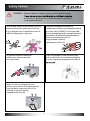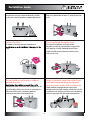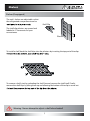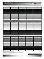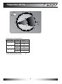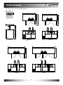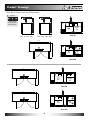
1
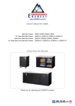
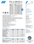
www.EVERESTref.com
Owner’s Manual for models:
Direct Draw Keg Refrigerators EBD1, EBD2, EBD3, EBD4
24" Deep Direct Draw Keg Refrigerators EBDS2-24, EBD2-24, EBD3-24, EBD4-24
Back Bar & Direct Draw Keg Refrigerators EBD2-BB, EBD2-BBG, EBD3-BB, EBD3-BBG
24" Deep Back Bar & Direct Draw Keg Refrigerators EBDS2-BB-24, EBD2-BB-24, EBD3-BB-24
EBDS2-BBG-24, EBD2-BBG-24, EBD3-BBG-24
Club Top Direct Draw Keg Refrigerators EBD2-CT, EBD3-CT, EBD4-CT
A Step Above the Standard
Thank you for selecting an EVEREST product
R
C
LI S
T ED
US
ISO-9001
Safety Notices
REFRIGERATION
WARNING - When using your appliance, always follow basic precautions, including
the following :
When installing the unit, be careful that the
electrical cord is not under the unit or
pressed against the wall.
This could cause a damage
to the cord.
time, make sure the unit
is free from all packaging.
Packaging left
on the unit
during
operation may
To prevent electrical shock, please do
not plug or unplug the cord
with wet hands.
Before cleaning or maintaining the unit,
please unplug it. Do not use any
around the unit.
Install the unit on a hard
and level surface.
Please do not hang or climb
on the unit as this may
cause the unit to fall.
Please do not store temperature
sensitive items in the unit,
such as medical or
science research
related materials.
If you suspect a refrigerant leak,
unplug the unit and
immediately contact an
authorized service
technician.
1
Safety Notices
REFRIGERATION
WARNING - Read and follow all safety notices in this installation guide.
information. Failure to do so may lead to serious injury and /
or damage to the unit.
To minimize shock and fire hazards, be sure
not to overload the outlet into which the
unit is plugged into. A dedicated circuit of
sufficient amperage is required.
To prevent damage to the electrical
components, have the unit plugged in directly
to its own circuit. EVEREST is not responsible
for any damage caused by improper electrical
connections resulting from electrical power
failure, use of extension cords &
surge protectors, and any
voltage drops to the unit.
To prevent electrical shock and
malfunction, do not spray the
unit with water.
Clean the pronges of the electrical plug
with a soft cloth or brush before plugging
it into an electrical receptacle to prevent a
When it is time to salvage the unit,
make sure to remove the rubber gaskets
from the doors to prevent the risk of
children or animals getting
trapped inside the unit.
2
Caution!
REFRIGERATION
To prevent electrical shock and damage to
the electrical cord, please hold
the plug head
when plugging
and unplugging
the unit.
Do not use the
electrical cord
or plug if they
are damaged
in any way.
To avoid personal injuries
from broken glass,
please do not
place glass items
in the freezer.
Avoid installing the
unit where it could
be exposed to
water or
moisture.
After unplugging the unit, please wait at
least 6 minutes
before re-plugging
it in. Failure to do
so could cause
extensive damage
to the compressor.
Please do not attempt to
remove or
repair any
components
unless you are
an authorized
service technician.
If the unit will
not be used for an
extended period of
time, please unplug
it from the outlet.
Do not put your hands under the unit when
moving it. You could be injured by sharp
edges, protruding parts,
crushing, etc.
The refrigerator compartment temperature
should be set at 32°F~41°F(See page 9).
Setting the temperature out of the recommended ranges will void the unit’s warranty.
3
Installation Guide
REFRIGERATION
Install the unit on a hard and level surface
or the unit could produce undesired noises.
The unit should be at least 2” away from the
wall.
Indoor Use Only
Dusty and High Humidity Areas
Outdoor use may cause a decrease in
Dusty environments will cause the
condenser coil to prematurely clog which
will require it to be cleaned more often.
High humidy environments could cause
the unit to rust.
unit.
Do not build an enclosure or cabinet
around the unit.
Select a location away from other heat
and moisture generating equipment
such as stoves, ovens, dish washers, etc.
condenser area will cause the compressor to
work harder, which can result in compressor
failure and the unit not being able to
maintain the desired temperature.
High ambient temperatures cause the
compressor to work harder, which can result
in compressor failure and the unit not being
able to maintain the desired temperature.
4
Maintenance Guide
REFRIGERATION
Shelf Cleaning
Door Gasket Cleaning
Periodically remove the shelves from the unit
and clean them
with mild soap
and warm water.
To preserve the life span of the door gaskets,
clean the gaskets
with mild soap
and water on
a regular basis.
Do not use the following products when cleaning
Clean the exterior of the product with mild soap and warm water.
Never use steel wool, strong acids, abrasive cleaners or degreasers.
Acidic products and products containing vinegar must be stored
in sealed containers to prevent corrosion to the interior of the
unit and the evaporator coil. (corrosion resulting from the lack
of or improper maintenance will not be covered under warranty).
Interior Cleaning
Clean the interior surface of the unit with mild soap and warm
water. Do not let water accumulate inside the unit. To prevent
water damage, wipe the interior of the unit with a dry cloth as
needed. Do not use abrasive cleaners, concentrated detergents,
bleaches, cleaning waxes, solvents or polishes to clean the interior
of the unit.
Condenser Coil Cleaning
Poor condensing unit performance is caused by heavy dust
build-up on the condenser coil. The condenser coil should be
condenser with a soft brush or a vacuum with a brush
attachment. The condenser coil should be cleaned in the
5
Trouble Shooting
REFRIGERATION
Please check the following before requesting service.
Symptom
Condensing unit
fails to start
Cabinet does not
maintain proper
temperature
Refrigerated
compartment is too
cold
Noisy operation
Condensation on the
exterior surface
Sound of water
dripping
Exterior walls are
warm
at
he
Condensation on the
interior
Possible Solutions
a. Ensure the electrical cord has been connected.
b. Ensure the unit is turned on.
a. Check the door gaskets for proper seal.
b. Check to see if the temp. control setting is too
high, then adjust as necessary.
c. Avoid installing the unit next to heat generating
equipment and direct sunlight.
d. Avoid storing hot contents.
e. Ensure the doors are fully closed.
a. Adjust the temperature control to a warmer
setting.
a. Check for loose parts.
b. Check for tubing rattle.
c. Check for a bent fan blade.
d. Check for damaged fan motor bearings.
e. Ensure the unit is stable.
f. Ensure the cabinet is level.
a. Condensation on the exterior surface of the
unit is perfectly normal during periods of high
humidity.
b. Check door alignment and gaskets for proper
seal.
a. This is the sound of the refrigerant circulating
during the compressor rest period and it is
normal.
a. Heaters have been placed around the door
openings to prevent condensation buildup.
This is normal.
a. Condensation can occur during hot and humid
weather with frequent or prolonged door opening.
This is normal.
b. The doors might not be closed properly. Check door
alignment and for proper seal.
6
Shelves
REFRIGERATION
Shelves(If equipped)
The unit’s shelves are adjustable so that
the refrigerated compartment can be
Shelf Clip
The shelf clip pilasters are spaced and
labeled in 1” increments for your
convenience.
Pilaster
1”
To install a shelf, hook the shelf clips into the pilasters by inserting the top part of the clips
To remove a shelf, start by unloading the shelf. Second, remove the shelf itself. Finally,
remove the shelf clips by tilting them up and allowing the bottom of the clip to come out
Warning - Never attempt to adjust a shelf when loaded!
7
Specifications
Specification
REFRIGERATION
Direct Draw Keg Refrigerators
Model
EBD1
EBD2
EBD3
EBD4
Capacity( Cu. Ft.)
Door(s)
Shelves
Compressor (HP)
8.19
1
1/6
20.09
2
1/4
24.01
2
1/4
32.37
3
1/3
Power (V-Hz-Ph)
Temp. Range (°F)
115-60-1
115 -60-1
115-60-1
115-60-1
32 - 42
32 - 42
32 - 42
32 - 42
Refrigerant
Crated Weight (LBS)
Amps (A)
R-134A
160
3.90
R-134A
275
4.50
R-134A
313
4.50
R-134A
363
4.50
Exterior Dimensions
23 1/2 x 31 1/2 a x 39 b
57 3/4 x 27 x 37
68 x 27 x 37
89 1/4 x 27 x 37
(W x D x H* inches)
24" Deep Direct Draw Keg Refrigerators
Model
EBDS2-24
EBD2-24
EBD3-24
EBD4-24
Capacity( Cu. Ft.)
Door(s)
Shelves
Compressor (HP)
13.95
2
1/4
16.86
2
1/4
20.41
2
1/4
27.76
3
1/3
Power (V-Hz-Ph)
Temp. Range (°F)
115-60-1
115 -60-1
115-60-1
115-60-1
32 - 42
32 - 42
32 - 42
32 - 42
Refrigerant
Crated Weight (LBS)
Amps (A)
R-134A
R-134A
R-134A
R-134A
250
4.50
49 x 24 1/2 x 37
280
4.50
57 3/4 x 24 1/2 x 37
297
4.50
68 x 24 1/2 x 37
380
4.50
89 1/4 x 24 1/2 x 37
Exterior Dimensions
(W x D x H* inches)
Back Bar & Direct Draw Keg Refrigerators
Model
EBD2-BB
EBD2-BBG
EBD3-BB
EBD3-BBG
Capacity( Cu. Ft.)
Door(s)
Shelves
20.09
2(SD)
2
20.09
1(SD), 1(GD)
2
24.01
2(SD)
2
24.01
1(SD), 1(GD)
2
Capacity
12 oz. Cans / Bottles
280 / 192
280 / 192
360 / 240
360 / 240
Compressor (HP)
1/4
115-60-1
1/4
115 -60-1
1/4
115-60-1
1/4
115-60-1
32 - 42
32 - 42
32 - 42
32 - 42
Refrigerant
Crated Weight (LBS)
Amps (A)
R-134A
280
4.50
R-134A
297
4.50
R-134A
320
4.50
R-134A
337
4.50
Exterior Dimensions
57 3/4 x 27 x 37
57 3/4 x 27 x 37
68 x 27 x 37
68 x 27 x 37
Power (V-Hz-Ph)
Temp. Range (°F)
(W x D†x H* inches)
[NOTE]
* Ext. height does not includes 5” for towers.
(This EBD1 model is equipped with pre-installed casters as standard feature).
† Depth does not include protruding door handle.
a Depth includes 1 1/2” for back grill.
b Height includes 5” for casters.
8
Specifications
Specification
REFRIGERATION
24" Deep Back Bar & Direct Draw Keg Refrigerators
Model
EBDS2-BB-24
EBD2-BB-24
EBD3-BB-24
Capacity( Cu. Ft.)
Shelves
13.95
2(SD)
2
16.86
2(SD)
2
20.41
2(SD)
2
Capacity
12 oz. Cans / Bottles
175 / 126
245 / 168
315 / 210
Compressor (HP)
1/4
115-60-1
1/4
115 -60-1
1/4
115-60-1
Door(s)
Power (V-Hz-Ph)
Temp. Range (°F)
Refrigerant
Crated Weight (LBS)
Amps (A)
32 - 42
32 - 42
32 - 42
R-134A
254
4.50
R-134A
277
4.50
R-134A
310
4.50
Exterior Dimensions
(W x D x H* inches)
49 x 24 1/2 x 37
57 3/4 x 24 1/2 x 37
68 x 24 1/2 x 37
Model
EBDS2-BBG-24
EBD2-BBG-24
EBD3-BBG-24
Capacity( Cu. Ft.)
13.95
1(SD), 1(GD)
2
16.86
1(SD), 1(GD)
2
20.41
1(SD), 1(GD)
2
175 / 126
245 / 168
315 / 210
Compressor (HP)
Power (V-Hz-Ph)
1/4
115-60-1
1/4
115 -60-1
1/4
115-60-1
Temp. Range (°F)
Refrigerant
Crated Weight (LBS)
Amps (A)
32 - 42
32 - 42
32 - 42
R-134A
263
4.50
R-134A
287
4.50
R-134A
325
4.50
49 x 24 1/2 x 37
57 3/4 x 24 1/2 x 37
68 x 24 1/2 x 37
Door(s)
Shelves
Capacity
12 oz. Cans / Bottles
Exterior Dimensions
(W x D†x H* inches)
Club Top Direct Draw Keg Refrigerators
Model
EBD2-CT
EBD3-CT
EBD4-CT
Capacity( Cu. Ft.)
20.09
2
1
1/4
115-60-1
24.01
2
1
1/4
115 -60-1
32.37
3
1
1/3
115-60-1
Door(s)
Shelves
Compressor (HP)
Power (V-Hz-Ph)
Temp. Range (°F)
Refrigerant
Crated Weight (LBS)
Amps (A)
Exterior Dimensions
(W x D x H* inches)
32 - 42
32 - 42
32 - 42
R-134A
293
4.50
R-134A
331
4.50
R-134A
373
4.50
57 3/4 x 27 x 37
68 x 27 x 37
89 1/4 x 27 x 37
[NOTE]
* Ext. height does not includes 5” for towers.
† Depth does not include protruding door handle.
9
Temperature Setting
REFRIGERATION
8
9
7
6
OFF
5
(℉ )
4
1
3
2
[Temperature Setting Range]
Setting Range
1 ~ 3
3 ~ 5
6 ~ 9
Comp.
On
Off
On
Off
On
Off
• Factory Recommended Setting:
REF (℉)
48
41
39
31
30
21
“5”
10
Product Drawings
REFRIGERATION
Direct Draw Keg Refrigerators
3/4" O.D.
31 1/2"
52"
22 3/4"
39"
34"
34"
50 3/4"
T-Shaped PVC
Drain Fittings w/
Moveable Plug
23 1/2"
1 1/2"
12"
16 3/4"
31 1/2"
30"
16 1/2"
5"
EBD1
Pre-installed casters
Top view
27"
15 1/2"
57 3/4"
16 3/4"
12"
37"
49"
53 3/4"
27"
22 3/4"
37"
22 3/4"
EBD2
Side View
68"
89 1/4"
27"
27"
EBD3
22 3/4"
EBD4
11
22 3/4"
37"
22 3/4"
37"
22 3/4"
49"
49"
22 3/4"
Product Drawings
REFRIGERATION
24" Deep Direct Draw Keg Refrigerators
3/4" O.D.
49"
57 3/4"
46 1/2"
24 1/2"
44 1/2"
39 3/4"
24 1/2"
T-Shaped PVC
Drain Fittings w/
Moveable Plug
24 1/2"
13"
16 3/4"
12"
53 3/4"
22 3/4"
22 3/4"
EBD2-24
EBDS2-24
68"
89 1/4"
24 1/2"
24 1/2"
EBD3-24
22 3/4"
EBD4-24
12
22 3/4"
37"
22 3/4"
37"
22 3/4"
46 1/2"
46 1/2"
22 3/4"
37"
Side View
16"
37"
37"
20 3/4"
Product Drawings
REFRIGERATION
Back Bar & Direct Draw Keg Refrigerators
3/4" O.D.
27"
15 1/2"
16 3/4"
12"
16 3/4"
12"
37"
37"
Side View
(EBD2-BB / EBD3-BB)
22 3/4"
Beer
Kegs
Side View
(EBD2-BBG / EBD3-BBG)
22 3/4"
Bottles
37"
53 3/4"
53 3/4"
T-Shaped PVC
Drain Fittings w/
Moveable Plug
27"
15 1/2"
&
Cans
EBD2-BB
57 3/4"
27"
22 3/4"
Bottles
&
Cans
EBD2-BBG
68"
27"
22 3/4"
Bottles
37"
49"
22 3/4"
Beer
Kegs
&
Cans
EBD3-BB
68"
27"
22 3/4"
Bottles
&
Cans
EBD3-BBG
13
37"
49 1/2"
22 3/4"
Beer
Kegs
37"
49"
22 3/4"
Beer
Kegs
Product Drawings
REFRIGERATION
24" Deep Back Bar & Direct Draw Keg Refrigerators
3/4" O.D.
49"
44 1/2"
39 3/4"
24 1/2"
T-Shaped PVC
Drain Fittings w/
Moveable Plug
24 1/2"
13"
16 3/4"
12"
16"
Beer
Kegs
Bottles
37"
53 3/4"
37 1/10"
20 3/4"
&
Cans
EBDS2-BB-24
57 3/4"
68"
46 1/2"
24 1/2"
46 1/2"
24 1/2"
22 3/4"
Beer
Kegs
&
Cans
EBD2-BB-24
22 3/4"
Bottles
&
Cans
EBD3-BB-24
14
37"
22 3/4"
Bottles
37"
22 3/4"
Beer
Kegs
Product Drawings
REFRIGERATION
24" Deep Back Bar & Direct Draw Keg Refrigerators
3/4" O.D.
49"
44 1/2"
40 1/4"
24 1/2"
T-Shaped PVC
Drain Fittings w/
Moveable Plug
24 1/2"
13"
16 3/4"
12"
53 3/4"
37"
16"
Beer
Kegs
Bottles
37"
20 3/4"
&
Cans
EBDS2-BBG-24
57 3/4"
68"
24 1/2"
24 1/2"
22 3/4"
Beer
Kegs
&
Cans
EBD2-BBG-24
22 3/4"
Bottles
&
Cans
EBD3-BBG-24
15
37"
37"
22 3/4"
Bottles
47"
47"
22 3/4"
Beer
Kegs
Product Drawings
REFRIGERATION
Club Top Direct Draw Keg Refrigerators
57 3/4"
23 1/16"
3/4" O.D.
12 3/4"
19 7/8"
27"
49"
12 3/4"
T-Shaped PVC
Drain Fittings w/
Moveable Plug
27"
15 1/2"
16 3/4"
12"
53 3/4"
22 3/4"
37"
37"
22 3/4"
EBD2-CT
Side View
68"
89 1/4"
23 1/16"
23 1/16"
12 3/4"
12 3/4"
19 7/8"
19 7/8"
27"
22 3/4"
22 3/4"
EBD3-CT
49"
49"
12 3/4"
27"
12 3/4"
22 3/4"
22 3/4"
EBD4-CT
16
22 3/4"
Installation
REFRIGERATION
Drilling Ports For CO2 Lines
Applicable Serial Numbers
BBD1-0801-XXXX ~ BBD1-1209-XXXX
BBD2-0801-XXXX ~ BBD1-1209-XXXX
BBD3-0801-XXXX ~ BBD1-1209-XXXX
BBD4-0801-XXXX ~ BBD1-1209-XXXX
Wall-integrated Drain Line
Left Back View
Right Back View
To avoid damaging refrigeration components and wiring, please drill holes for CO2 lines only in the highlighted areas.
For further assistance, please contact our Technical Support Department at 1-800-444-6285.
17
Installation
REFRIGERATION
Drilling Ports For CO2 Lines
Applicable Serial Numbers
BBD1-1210-XXXX ~ Present
BBD2-1210-XXXX ~ Present
BBD3-1210-XXXX ~ Present
BBD4-1210-XXXX ~ Present
Left Back View
Right Back View
To avoid damaging refrigeration components and wiring, please drill holes for CO2 lines only in the highlighted areas.
For further assistance, please contact our Technical Support Department at 1-800-444-6285.
18
Installation Instructions
REFRIGERATION
* Air distributor is only on multiple keg units, each keg
is conneted to a valve on the air distributor.
Single keg is connected directly to the regulator.
Faucet Handle
Tower Cover
Faucet
Tower
Co2 Regulator
Co2 Distributor*
Beer Line
Keg Coupler
Co2 Tank
Keg
NOTE
The keg, keg coupler, CO2 regulator, CO2 tank, keg coupler to CO2 distributor line, and CO2 distributor to CO2 regulator line,
are not included with your keg refrigerator. These items can be obtained from your beverage distributor. The beer tower with
faucet, faucet handle, tower beer line, and CO2 distributor are included.
19
Installation Instructions
REFRIGERATION
1
Position tower gasket so that the drain line and screw holes align properly with
the top surface of the unit. Feed the tower’s beer line through the unit’s beer line hole.
2
Secure the tower to the unit using the four screws provided.
20
Installation Instructions
REFRIGERATION
3
Insert the end of the cold air hose without a hook into the air baffle.
4
Remove the beer tap tower’s cap.
Insultion(Foam)
5
Feed the end of the cold air hose with a hook through
the bottom of the tower and attach the hook to the
beer tap retaining nut.
Insultion(Foam)
Hook
21
Installation Instructions
6
REFRIGERATION
Replace the beer tap tower’s cap.
3/4" O.D.
T-Shaped PVC
Drain Fittings w/
Moveable Plug
22
Keg Installation Instructions
REFRIGERATION
* NOTE: The CO2 distributor can be used to share the single CO2 tank with multiple kegs.
1. CO2 tank placement (inside or outside of the refrigerated cabinet)
a. Outside of Cabinet - Drill a hole on the back wall of the unit, only in the areas indicated in figure;
Drilling in any other place may cause damage to the unit's wiring.
b. Inside of Cabinet – Depending on the unit model and size of the equipped keg, you may be able to fit
the CO2 tank inside of the refrigerated cabinet; This setup requires no drilling.
2. Connect CO2 Line to CO2 Regulator
a. Ensure that the CO2 regulator's shut off valve is closed.
The switch's lever should be perpendicular to the CO2 line when it is in the closed position.
b. Connect one end of the CO2 line to the CO2 regulator's hose barb connection,
pushing the hose onto the barb connector as high as you can without damaging the hose.
Secure the hose to the connector using a clamp. Place the clamp as high up as possible
without it interfering with the operation of the valve.
c. If the CO2 tank has been placed out of the refrigerated cabinet,
feed the hose through the hole that was previously drilled in the back of the unit.
3. Connect CO2 Regulator to CO2 tank
a. Ensure that the CO2 tank is full and closed.
b. Attach the CO2 regulator to the CO2 tank using the large nut that is part of the regulator.
4. Connect Keg Coupler
a. IMPORTANT: Ensure that the keg pull handle is closed (upper position).
b. Install the keg coupler onto the keg's locking neck and turn clockwise to lock into place.
5. Connect CO2 Line to Keg Coupler
a. Connect the open end of the CO2 line to the keg coupler's hose barb connection,
pushing the hose onto the barb connector as high as you can without damaging the hose.
Secure the hose to the connector using a clamp. Place the clamp as high up as possible
without it interfering with the operation of the valve.
6. Connect Beer Line to Keg Coupler
a. Install the rubber washer onto the beer line hex nut fitting.
b. Remove the plastic protective cover from the keg coupler, if equipped.
c. Connect the beer line from the tower to the keg coupler.
It connects to the screw type connection on top of the coupler.
7. Tap Keg
a. Pull the tap handle out and away from the keg coupler and push down until it locks into position.
A click noise should be heard once the handle is in its final lock position.
23
Keg Installation Instructions
REFRIGERATION
* NOTE: The CO2 distributor can be used to share the single CO2 tank with multiple kegs.
8. Calibrating CO2 Regulator
a. With the shut-off valve on the CO2 regulator closed, open the valve on the CO2 tank completely.
b. Loosen the adjustment nut with a pair of pliers, allowing the adjustment screw to be turned
counter-clockwise until the screw can no longer turn.
c. Slowly turn the CO2 regulator adjustment screw until the desired pressure is shown on the output
pressure gauge (12 PSI is recommended setting for most situations). Other conditions, such as altitude or
special beer type, may require some adjustment. On regulators designed for draft beer, turning clockwise
will increase the output pressure, and turning counter-clockwise will decrease the output pressure.
d. Open the shut-off valve on the CO2 regulator, ensuring the switch below the main body should be parallel
to the tubing. Gas should now flow from the regulator to the keg coupler, and you will hear the keg
pressurizing. The output needle will drop momentarily while the pressure is equalizing, then it will return to
the point at which you set it.
e. The keg coupler is designed with a pressure relief valve (PRV). Pull the ring on the PRV
briefly to allow gas to vent. This will permit gas to flow through the regulator and help obtain a more
accurate reading on the output pressure gauge.
f. Re-check the output pressure on the regulator and, if necessary, re-adjust using step 8.3 until the desired
pressure is shown. It is always wise to follow up any adjustment to the regulator with a brief pull of the PRV
ring to ensure an accurate output reading.
9. Position the keg in the refrigerated compartment. Ensure that no hoses are kinked or
crushed.
24
Critical Information
REFRIGERATION
CONDENSER COIL MAINTENANCE
Failure to maintain a clean condenser coil will eventually result in compressor failure and product loss.
Mechanical failures due to a lack of or improper maintenance are not covered under warranty.
Keeping the condenser coil clean will maximize energy savings.
Cleaning of the condenser coil is part of regular maintenance and is not covered under warranty.
CONDENSER COIL CLEANING PROCEDURE
Please use the following steps to clean the condenser coil. If you have any questions regarding this
procedure, please call the Everest customer service department at (800) 444-6285.
1. Unplug the unit from the wall.
2. Remove the ventilation grill located at the left side or back of the unit, depending on the model.
The grill is secured by Philips head screws.
3. Slide out the condensing unit enough so that the condenser coil can be cleaned. The condensing unit
is on a tray which can be slid out by removing the Philips head screws securing the slide out tray
to the unit.
4. Clean the condenser coil using a vacuum or brush. The fins of the condenser coil should only be cleaned
and swept in the direction of the fins, which is up and down. Be careful not to bend the fins.
5. In some instances, the condenser coil may require professional cleaning due to a buildup of grease and
dust. In this case, contact a local refrigeration company to take care of this for you.
6. Push the slide-out condenser tray fully home once cleaning is completed.
7. Secure the condenser tray using the Philips head screws that were removed in step 3.
8. Before securing the ventilation grill back onto the unit, be sure that all tools have been removed from
the condenser area and that nothing will obstruct the motion of the condenser fan blade.
9. Replace the ventilation grill onto the back of the unit using the Philips head screws removed in step 2.
The warranty card below must be submitted to Everest within thirty (30) days of purchase.
WARRANTY REGISTRATION CARD
Business Name :
Telephone : (
)
Address :
City :
State :
Place of Purchase :
Zip :
Date Purchased :
Model No :
Date Installed :
Cabinet Serial No :
3 YEAR PARTS and LABOR WARRANTY
(Applicable to units purchased after July 1, 2014.)
5 YEAR COMPRESSOR WARRANTY
Name of Business Owner :
Date :
Signature of Business Owner :
25
Warranty Certificate
REFRIGERATION
EVEREST warrants to the original purchaser of every new EVEREST unit, the cabinet and all parts thereof, to be free from defects in
material or workmanship, under normal and proper use and maintenance service as specified by EVEREST and upon proper
installation and start-up in accordance with the instruction packet supplied with each unit. Our obligation under this warranty is
limited to a period of three (3) years from the date of original installation or thirty six (36) months after shipment date from EVEREST,
which ever occurs first. This is applicable to units purchased after July 1, 2014. Any part covered under this warranty that is determined
by EVEREST to have been defective within three (3) years of original installation or thirty six (36) months after shipment date from the
manufacturer, which ever occurs first, is limited to the repair or replacement, including labor charges, of defective parts or assemblies.
The labor warranty shall include standard straight time labor charges only and reasonable travel time, as determined by EVEREST.
All warranty claims for labor or parts must be made directly through EVEREST. All claims shall include: unit model number, cabinet
serial number, proof of new product purchase, installation date, and all pertinent information related to the alleged defect. For
compressor warranty claims, the compressor tag shall be returned to EVEREST with the above listed information.
EVEREST's sole obligation under this warranty is limited to either the repair or replacement of parts, subject to the additional limitations
below. This warranty neither assumes nor authorizes any person to assume obligations other than those expressly covered by this
warranty.
A. NON WARRANTY PARTS
EVEREST excludes specific parts exposed to normal wear and tear. These parts include, but are not limited to, lamps,
gaskets, casters, shelves and shelf clips, pans, bin and pan dividers and airflow guards.
B. INDIRECT OR CONSEQUENTIAL DAMAGE
EVEREST does not warrant economic loss, profit loss, or special, indirect or consequential damages including without
limitation, losses or damages arising from food or product spoilage claims caused by refrigeration failure.
C. IMPROPER USAGE
EVEREST is not responsible for parts or labor coverage for component failure and or other damages resulting from
improper usage, installation or failure to clean and/or maintain product as set forth in the user's manual provided with this
unit. All EVEREST products are designed for commercial usage, not for residential use. Therefore, the warranty will not be
honored if product is installed in a residential house.
D. WARRANTY IS NOT TRANSFERABLE
Warranty is limited to only the original purchaser/user to whom delivered. It is not transferable.
E. ALTERATION, NEGLECT, MISUSE, ABUSE, ACCIDENT, DAMAGE DURING TRANSIT OR INSTALLATION, FIRE, FLOOD, ACTS
OF GOD.
EVEREST is not responsible for malfunctions due to alteration, neglect, misuse, abuse, accident, damage during transit or
installation, fire, flood, storm, and/or other acts of God. And EVEREST is not responsible for any improper electrical
connections resulting from electrical power failure, the use of extension cords, and low voltage or voltage drops to the unit.
F. UNAUTHORIZED MODIFICATION
EVEREST is not responsible for the repair or replacement of failed or damaged components resulting from unauthorized
modifications to units or the use of non-standard parts without prior written approval from EVEREST.
G. RESIDENTIAL, NON-COMMERCIAL USE
This warranty does not apply to a unit installed in a residential setting. This unit is for commercial use only.
H. OUTSIDE THE U.S.
This warranty does not apply to any parts and/or labor warranty claims made on units sold or used outside of the United
States.
ADDITIONAL TWO(2) YEAR COMPRESSOR WARRANTY
In addition to the warranty set forth above, EVEREST warrants the hermetically sealed compressor for an additional two (2) years, not
to exceed sixty (60) months from the date of shipment from EVEREST, provided upon receipt of the compressor, manufacturer
examination shows the sealed compressor to be defective. This compressor warranty does not apply to shipping or labor costs or
any other parts of the unit whether electrical or mechanical.
These warranties are exclusive and in lieu of all other warranties, expressed or implied, and all other obligations or liabilities on our
part, and we neither assume nor authorize any other person to assume for us any other obligation or liability in connection with
the sale of said refrigeration units or any part thereof.
26
REFRIGERATION
REFRIGERATION
A Step Above the Standard
201 W. Artesia Blvd., Compton CA 90220
Tel : 310-323-6586, 800-444-6285
Fax : 310-323-7524, 310-761-1127
Visit our website at www.EVERESTref.com