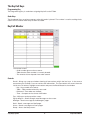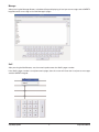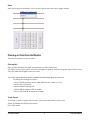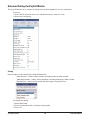
1
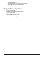
KeyCall
U S E R M A N UA L
E
VIC
SE R
I n s t a l l a t i o n , Wa r r a n t y a n d S e r v i c e I n f o r m a t i o n
Long Range Systems UK Ltd | Link House | Leek Road | Milton | Stoke on Trent | Staffordshire | ST2 7AH | 01782 537000
www.lrspagers.co.uk | www.pagers.co | www.hospitalpagers.co.uk
Table Of Contents
Installation and Setup . . . . . . . . . . . . . . . . . . . . . . . . . . . . . . . . . . . . . . . . . . . .
2
Basic Installation . . . . . . . . . . . . . . . . . . . . . . . . . . . . . . . . . . . . . . . . . . . . . . . . . . . . .
2
SD Card . . . . . . . . . . . . . . . . . . . . . . . . . . . . . . . . . . . . . . . . . . . . . . . . . . . . . . . . . . . . .
3
Key Call . . . . . . . . . . . . . . . . . . . . . . . . . . . . . . . . . . . . . . . . . . . . . . . . . . . . . . .
4
Typical KeyCall Setup . . . . . . . . . . . . . . . . . . . . . . . . . . . . . . . . . . . . . . . . . . . . . . . . .
4
Associate KeyCall Units . . . . . . . . . . . . . . . . . . . . . . . . . . . . . . . . . . . . . . . . . . . . . . . .
5
Mounting the KeyCall . . . . . . . . . . . . . . . . . . . . . . . . . . . . . . . . . . . . . . . . . . . . . . . . .
5
Using the KeyCall . . . . . . . . . . . . . . . . . . . . . . . . . . . . . . . . . . . . . . . . . . . . . . . . . . . . .
5
The KeyCall Keys . . . . . . . . . . . . . . . . . . . . . . . . . . . . . . . . . . . . . . . . . . . . . . . . . . . . .
6
KeyCall Monitor . . . . . . . . . . . . . . . . . . . . . . . . . . . . . . . . . . . . . . . . . . . . . . . . . . . . . .
6
Clearing an Order from the Monitor . . . . . . . . . . . . . . . . . . . . . . . . . . . . . . . . . . . . .
8
Advance Settings for KeyCall Monitor . . . . . . . . . . . . . . . . . . . . . . . . . . . . . . . . . . .
10
Reports . . . . . . . . . . . . . . . . . . . . . . . . . . . . . . . . . . . . . . . . . . . . . . . . . . . . . . . . . . . . .
14
KeyCall Operation Using Server Section Assignments . . . . . . . . . . . . . . . . . . . . . .
17
Entering Employees . . . . . . . . . . . . . . . . . . . . . . . . . . . . . . . . . . . . . . . . . . . . . . . . . .
18
Creating an Employee Database . . . . . . . . . . . . . . . . . . . . . . . . . . . . . . . . . . . . . . . .
18
Editing Employees
...................................................
18
Creating a List of Tables . . . . . . . . . . . . . . . . . . . . . . . . . . . . . . . . . . . . . . . . . . . . . . .
19
Assign Section . . . . . . . . . . . . . . . . . . . . . . . . . . . . . . . . . . . . . . . . . . . . . . . . . . . . . . .
19
Basic Operations . . . . . . . . . . . . . . . . . . . . . . . . . . . . . . . . . . . . . . . . . . . . . . . .
21
Troubleshooting
................................................
22
Replacing a KeyCall Unit or Adding Additional Units . . . . . . . . . . . . . . . . . . . . . . .
22
Touch-Screen Shows Nothing . . . . . . . . . . . . . . . . . . . . . . . . . . . . . . . . . . . . . . . . . .
22
Battery Powered Pagers Don’t Receive Pages . . . . . . . . . . . . . . . . . . . . . . . . . . . . . .
22
Changing the Manager Pager Number . . . . . . . . . . . . . . . . . . . . . . . . . . . . . . . . . . .
23
........................................................
24
Replacing the T7503 . . . . . . . . . . . . . . . . . . . . . . . . . . . . . . . . . . . . . . . . . . . . .
25
System Specifications . . . . . . . . . . . . . . . . . . . . . . . . . . . . . . . . . . . . . . . . . . . .
26
Transmitter . . . . . . . . . . . . . . . . . . . . . . . . . . . . . . . . . . . . . . . . . . . . . . . . . . . . . . . . . .
26
Auxiliary TX/RX Devices (KeyCall, Table Genie, etc) . . . . . . . . . . . . . . . . . . . . . . . .
26
Battery Powered Pagers . . . . . . . . . . . . . . . . . . . . . . . . . . . . . . . . . . . . . . . . . . . . . . .
26
Rechargeable Pagers . . . . . . . . . . . . . . . . . . . . . . . . . . . . . . . . . . . . . . . . . . . . . . . . . .
26
Questions and Answers . . . . . . . . . . . . . . . . . . . . . . . . . . . . . . . . . . . . . . . . . . .
27
Warranty . . . . . . . . . . . . . . . . . . . . . . . . . . . . . . . . . . . . . . . . . . . . . . . . . . . . . . .
28
Znode
Long Range Systems
1
KeyCall User Manual
INSTALLATION AND SETUP
Basic Installation
Caution: Do not mount the transmitter near any large metal objects.
1) Un-wrap all system components.
2) Setup 17” Touch-screen Monitor near kitchen area.
3) Place T7502 next to Touch-screen Monitor.
4) Twist the 3” antenna onto the silver connector located at the rear of the transmitter.
5) Connect the VGA Cable of the Touch-screen Monitor to the VGA port on the back of the transmitter.
6) Connect the USB Cable of the Touch-screen Monitor to the USB port on the back of the transmitter.
7) Plug the Touch-screen Monitor’s power supply into a standard 110/220V outlet, and connect the
barrel end into the monitor’s Power port.
8) Turn on the Touch-screen Monitor.
9) Plug the transmitter 10V AC power supply into a standard 110/220V outlet, and connect the barrel end into the port located on the rear of the transmitter.
10) After 1 minute, the T7502 keyboard lights will stop chasing. Enter the current Time and Date (US
Format HH:MM am/pm, and MM/DD/YY.)
11) If required – The Touch-screen Monitor may require a calibration test after powering on the transmitter. Press the center of the 4 crosshairs to complete calibration.
9VAC
COM
UHF Antenna
LAN Port
10VAC Power
USB Cable from
Touch-Screen
VGA Output to
Touch-Screen
Back of Touch Screen Monitor
VGA Input from T7502
Power to Touch-Screen
USB Cable to T7502
Long Range Systems
2
KeyCall User Manual
To Put into KeyCall Operation Mode
1. Press Setup
2. Enter access code (Default access code: 5-6-7-8-9)
3. Select global settings
4. Select operation mode
5. From drop down box select KeyCall Monitor and press ENTER
6. Press Exit
7. Select YES to save changes
SD Card
The SD Card can maintain a backup of and can be used to transfer the information from an old T7502 onto
a new/replacement T7502.
If the SD Card is removed or missing, the card can be inserted into the slot on the right side of the transmitter.
After it is inserted, a pop-up window will show that a New Card is Detected, and will give options to select
to use as a Live Backup or to Clone T7502 from the SD Card if the card is transferred from one T7502 to another.
Long Range Systems
3
KeyCall User Manual
KEYCALL
Typical KeyCall Setup
KeyCall Unit
Thread lock
Battery Cover
Mounting Plate
1. Unpack the KeyCall unit, contents include:
• 1 - KeyCall unit
• 3 - AA Batteries
• 2 - Pieces of Foam Tape
• 1 - thread lock
• 1 - Battery cover with 2 screws
• 1 – Mounting Plate
2. To assemble, place the 3 AA batteries into the KeyCall.
3. Place the Thread-lock into the Housing with the teeth
facing down.
4. Place the Battery Cover over the Battery Compartment,
screw in place with the 2 Screws.
Long Range Systems
4
KeyCall User Manual
Associate KeyCall Units
1) Position KeyCalls at least 6 feet from T7502.
2) On T7502, press SETUP and enter access code (Default code is 5-6-7-8-9)
3) Go to Key Call Settings
4) Select Associate. The T7502 will stay in associate mode for 300 seconds (5 minutes); afterwards,
the user will need to restart the mode.
5) Place 3 AA batteries into KeyCall unit.
6) The Red light will begin flashing slowly, and then fast, and finally the Green light will flash once
and stop. A pop-up window will appear on the screen.
7) Assign the unit as a Clearing Unit, Starting Unit, or set a Table Number.
Note:
- Table Numbers can include letters and numbers in the designation.
8) Repeat for all units to be assigned.
9) Press EXIT to end associate mode when finished.
Mounting the KeyCall
1. Place the Mounting Plate on the desired location
using the 2 pieces of double sided foam tape or
using 4 screws. (Screws Not Includeded)
2. Place the KeyCall unit onto the Mounting Plate,
press down, then turn the unit counter-clockwise
to lock (unit should spin freely without pulling off
the Mounting Plate.)
Using The KeyCall
Starter Unit
The Starter Unit is located near the cashier or starting point of a transaction. After an order is placed, insert
the Key into the Starter Unit, observe beginning of Elapsed Time on the Orders window with order number.
Clearing Unit
The Clearing Unit is located near food pickup area. After a patron’s order has been delivered and Key retrieved, insert the Key into the Clearing Unit to confirm completion of the transaction.
Service Button
Alerts the Server by sending a page that a Table requires assistance. This will also cause the LEDs at the top
of the KeyCall unit to flash.
There is a one-minute time limit between signals sent to the Server pager when the button is pressed to reduce unnecessary requests.
Key Holder
Each KeyCall has four spaces (two on each side) to store Keys.
Long Range Systems
5
KeyCall User Manual
The KeyCall Keys
Programming Key
The Programming Key is used when assigning KeyCall’s to the T7502.
Order Keys
The Numbered Keys are given to patrons after their order is placed. The number is used in tracking the location of the customer when they sit down at a table.
KeyCall Monitor
The monitor shows:
• Order number given to the customer.
• Table that the Order number is currently located.
• The amount of time elapsed since order started.
Controls
Recall – Brings up a pop-up window showing all transactions within the last hour. In the event a
transaction was Cleared, a user can retrieve the information. The Transaction will resume from the
initial start. To retrieve, highlight a transaction and press the Recall Button in the window.
• Key – Key number of customer.
• Table – Table number where Key was used.
• Delivered – Time order was cleared.
• Time – Compete service time to fulfill order.
Top – Will return to the top of the screen.
Pg Up & Pg Dn – Scroll through more Messages on the screen.
Manager – Send a message to the Manager’s pager.
Staff – Sends a message to a Staff pager.
Guest – Sends a message to a Guest pager.
Setup – Access the Setup menu.
Long Range Systems
6
KeyCall User Manual
Manager
After pressing the Manager Button, a window will open displaying a list of pre-set messages and a QWERTY
keypad to enter a message sent to the Manager’s pager.
Staff
After pressing the Staff button, use the numeric pad to enter the Staff’s pager number.
If the Staff’s pager number is an alphanumeric pager, then the screen will show the list of pre-set messages
and the QWERTY keypad.
Long Range Systems
7
KeyCall User Manual
Guest
After pressing the Guest button, use the numeric pad to enter the Guest’s pager number.
Clearing an Order from the Monitor
There are two options to clear an order:
Clearing Unit
After an order has been delivered, insert the Key into the Clearing Unit.
The Lights on the Clearing Unit will flash red and green quickly, and then the green light will flash once.
Then the Order will disappear from the screen.
The Clearing Unit operation can be enabled or disabled depending on preference.
To change the Clearing Unit status:
1) Press SETUP and enter access code (Default access code: 5-6-7-8-9)
2) Enter Key Call Settings.
3) Select Enable Clearing Unit.
4) Select ON to enable or OFF to disable.
5) Press EXIT and OK to accept the changes.
Touch-Screen
To remove an order using the Touch-screen, select one of the orders on the screen.
A pop-up window will display Clear Order?
Press Clear Order.
Long Range Systems
8
KeyCall User Manual
Clearing an order can also be set to require a Manager’s Access Code at the Monitor.
To set:
1) Press SETUP and enter access code. (Default access code: 5-6-7-8-9)
2) Enter Key Call Settings.
3) Select Clear Requires Manager.
4) Select YES to require the code, or NO.
5) Press OK.
6) Press EXIT and press OK to accept the changes.
Long Range Systems
9
KeyCall User Manual
Advanced Settings for KeyCall Monitor
The KeyCall Monitor has a number of settings that can be changed to fit a user’s preferences.
To access:
1) Press SETUP and enter the access code (Default access code: 5-6-7-8-9)
2) Enter Key Call Settings.
Sorting
KeyCall orders can be sorted on the KeyCall Monitor by:
- Order Number – Orders will be sorted in ascending order by order number.
- Table/Seat Number – Orders will be sorted by ascending order by the table number.
- Elapsed Time – Orders will be sorted with the longest running time first.
To change the setting:
1) Select Sort Order
2) From the drop down box, select the sorting mode.
3) Press OK
Long Range Systems
10
KeyCall User Manual
4) Press EXIT and press OK to accept the changes
Alternatively:
Press the ORDER, TABLE, or TIME sections on the Monitor to sort by that method.
Service Goals
Warning Time is the time that is considered acceptable for order deliveries. Using the Warning Time and Service Goal Exceeded fields, the KeyCall Monitor can display how long an order is up before the time elapsed
is considered unacceptable for its delivery.
The Warning Time and Service Goal Exceeded times are set in seconds (180 = 180 seconds)
Any Order time under the Warning Time will appear white on the monitor.
After the Warning Time but before the Service Goal Exceeded time, the Order will change to yellow on monitor.
When the Service Goal Exceeded time passes, the Order will change to Red and the Manager’s Pager will receive a notification page.
To change either Service Goal setting:
1) Select Warning Time or Service Goal Exceeded.
2) Using the numeric keypad, enter a time in seconds.
3) Press OK.
4) Press EXIT and press OK to accept the changes.
Manager Pager
The Manager Pager setting sets the Pager Number of the Manager who will be paged after the Service Goal
Exceeded has passed with a Late Message and a Table Number.
Example: Service Goal Exceed time set to 4 minutes and 25 seconds
The Manager Pager will receive the current Alert Message, example “Late Order 12”
To change the Manager’s Pager Number:
1) Select Manager Pager
2) Using the numeric keypad, enter the pager number
3) Press OK
4) Press EXIT and press OK to accept the changes
Order Repage Time
This is the number of seconds between pages to the Server Pager when an order or message is sent from a
KeyCall.
To change the Server Pager Number:
1) Select Order Repage Time
Long Range Systems
11
KeyCall User Manual
2) Using the numeric keypad, enter the time (in seconds)
3) Press OK
4) Press EXIT and press OK to accept the changes
Alert Message
The Alert Message is the notification sent to the Manager when an order is past the Service Goal Exceeded
time.
To change the message:
1) Select Alert Message
2) Use Alpha keypad, enter a new message
3) Press OK
4) Press EXIT and press OK to accept the changes
Order Columns
The Order Columns settings will set the number of viewable columns to 1, 2, or 3.
To set:
1) Select Order Columns
2) Enter a value of 1, 2, or 3
3) Press OK
4) Press EXIT and press OK to accept the changes
KeyCall Button Messages
The KeyCall unit KeyCall Buttons will send a default message of “Service” to the Server Pager when pressed.
To change the messages sent :
1) Select Message 1 or Message 2
Note: Message 2 will only be used if Single Button Mode is turned OFF
2) Use Alpha keypad, enter a new message
3) Press OK
4) Press EXIT and press OK to accept the changes
KeyCall Button Mode
The KeyCall Service Buttons each send the same default message to the Server Pager.
To change the button mode to allow each button to send different messages:
1) Select Single Button Mode
2) Select OFF to allow each button to send a different message
Note: If Single Button Mode is ON, both buttons will send Message 1.
3) Press OK
4) Press EXIT and press OK to accept the changes
Long Range Systems
12
KeyCall User Manual
Beep on Error
The KeyCall units can give an “error beep” when the unit either fails to connect to the T7502 or when a Key
is not inserted properly.
This feature can be enabled or disabled by
1) Select Beep on Error
2) Select OFF to disable or ON to enable beeping on an error
3) Press OK
4) Press EXIT and press OK to accept the changes
Beep Volume
The volume of an “error beep” from a KeyCall Unit can be changed.
This feature raises or lowers the volume
1) Select Beep Volume
2) Use the numeric keypad to enter a new value for the volume (1 is low, 9 is high)
3) Press OK
4) Press EXIT and press OK to accept the changes
Low Battery Alert
The Low Battery Alert is based on a percentage of battery life that is set to determine if batteries are considered Low and need to be replaced.
When the Low Battery setting is reached, the KeyCall Monitor will show a RED “Low Battery” in the bottom
right corner. When the level is above the Low Battery level, the status will show a GREEN “Batteries OK”.
To view the battery status on the KeyCall Monitor, press the “Batteries OK”/”Low Batteries” button on the
bottom right corner, and a window will appear displaying the status of all KeyCall Units.
Any units with a low battery will be highlighted in RED
Long Range Systems
13
KeyCall User Manual
To change the Battery Level:
1) Select Low Battery (Default is set to 10, for 10%.)
2) Using the numeric keypad, enter the new level
3) Press OK
4) Press EXIT and press OK to accept the changes
Reports
The T7502 provides two reporting tools to view the Server’s efficiency with the KeyCall System.
- KeyCall Response by Time
- KeyCall Detail
KeyCall Response By Time
This report will display the hourly or daily information of:
- The number of orders from all KeyCalls
- The Average Elapsed Time of orders (in minutes
and seconds)
- The number of White Orders where the Server
responded in time
- The number of Yellow Orders where the order
changes from white to yellow
- The number of Pages sent to the Manager at the
Service Goal Exceeded time.
To access the report:
1) Press SETUP and enter the access code (Default
code is 5-6-7-8-9)
2) Select REPORTS
3) Select the KeyCall Response by Time
Long Range Systems
14
KeyCall User Manual
4) Set the Interval to Time of Day or Day of Week (If set to Day of Week, also set the day to start the week)
5) Select the Start and Stop Dates
6) Press Run Report
Example of
Response by Hour
Example of
Response by Day
Long Range Systems
15
KeyCall User Manual
KeyCall Detail
This report will display the information of all KeyCall transactions that occurred in the selected date range.
- The timing information of each individual order
- The Individual Order Number
- The Average Elapsed Time of orders (in minutes and seconds)
- The table each order sat at
- The number of Yellow Orders where the Service Goal was missed (time
when order changes from white to yellow)
- The number of Pages sent to the Manager at the Service Goal Exceeded time.
To access the report:
1) Press SETUP and enter the access code
(Default code is 5-6-7-8-9)
2) Select REPORTS
3) Select the KeyCall Response by Time
4) Set the Interval to Time of Day or Day of
Week (If set to Day of Week, also set the day
to start the week.)
5) Select the Start and Stop Dates
6) Press Run Report
KeyCall Detail Report
Daily Reports
Daily Error Reports will display at 12:00 AM of each day that the status of any KeyCall that has a low battery
or the T7502 has lost communication with.
Long Range Systems
16
KeyCall User Manual
KeyCall Operation Using Server Section Assignments
The KeyCall system can be set up to have sections of tables page different servers when the Service Buttons
are pressed.
To create Section Assignments:
1) Create an employee database (see Page 17)
2) Create a list of tables with Add/Remove Tables (see Page 18)
3) Assign Sections (see Page 18)
4) Assign Servers to sections (see Page 19)
Long Range Systems
17
KeyCall User Manual
Creating an Employee Database
The Employee Database will list the names of all the employeesusing the KeyCall system and display their
set roles and assigned pager number.
Entering Employees
1) Press SETUP and enter access code (Default code is 5-6-7-8-9)
2) Enter EMPLOYEES
3) Select EDIT EMPLOYEES
4) Press ADD
5) Use the keypad to enter the Employee’s Name
6) Press NEXT
7) Select the Employee’s Role
8) Press NEXT
9) Enter the pager number assigned to the Employee
10) Press FINISHED
11) Repeat steps 4 through 10 for each Employee to add
Editing Employees
1) From the EMPLOYEES, EDIT EMPLOYEES menu:
2) Enter EMPLOYEES.
3) Select EDIT EMPLOYEES.
4) Use the keypad to edit the Employee’s Name.
Long Range Systems
18
KeyCall User Manual
5) Press NEXT.
6) Edit the Employee’s Role.
7) Press NEXT.
8) Change the pager number assigned to the Employee.
9) Press FINISHED.
Creating a List of Tables
A list of tables is automatically created when each KeyCall is Associated to the System.
The number assigned to each Table Unit, corresponds to that unit’s Table Number.
Note: If a Table Unit’s Number is changed, the new number will need to be re-assigned to the Table Section,
and the old number removed from that Table Section.
Assign Sections
From KeyCall Settings menu:
1) Select Edit Table Sections
2) Set the number of Servers for the section.
3) From the Available Tables List, highlight a table.
4) Press the Add button to add to Tables in Section.
5) Repeat steps 3 and 4 for all Tables to Add to section.
6) Go to Section Number and create a new section.
7) Repeat steps 3 through 5 for adding Tables to the new section.
8) Press OK when done.
Note: The Remove button will remove any undesired Tables from a section assignment and return it to the
list of available tables.
Example list of Tables
Long Range Systems
Example list of Tables 1, 2,
and 13 added to Section
19
KeyCall User Manual
Assign Servers to Sections
From Key Call Settings menu
1) Select Assign Servers.
2) Select the number of Servers.
3) Highlight a section and press Enter (or tap twice on touchscreen).
4) From the Choose Server pop-up window, select a Server.
5) Press Assign to assign that Server or press Close Section to not assign a server to the Section.
6) Repeat Steps 3 through 5 for all Sections to Assign.
Example list of Servers
Assigned to 3 Sections.
Long Range Systems
20
KeyCall User Manual
BASIC OPERATION
The Cashier taking orders should ALWAYS demonstrate to the customer how to insert and remove a Key
using the Starter Unit. This will start the timer on the touch-screen PC and lead to better reports on service.
The customer takes the Key to any table and inserts and removes the Key in the KeyCall Table Unit. They
can place it in the holder on the side of the KeyCall or lay it on the table.
The Table number appears next to the Order number on the touch-screen monitor.
When the food order is ready, the runner takes the order to the table on the screen.
The runner picks up the key, returns to the food service area, and inserts the key into the Clearing Unit to complete the cycle.
Keys are taken back to the cashier throughout the shift.
Long Range Systems
21
KeyCall User Manual
TROUBLESHOOTING
Replacing a KeyCall Unit or Adding Additional Units
When receiving a new KeyCall unit from LRS, the unit must be “associated” to the system.
1) On the T7502 Press the Setup and enter the access code (Default code is 5-6-7-8-9)
2) Go to KeyCall settings
3) Select Associate
4) Insert batteries into KeyCall unit.
5) Insert and remove PROGRAM key.
6) The Red light will begin flashing slowly, and then fast, and finally the Green light will flash once
and stop.
7) A pop up window will appear on the screen. Assign the unit as a Starter Unit, Clearing Unit, or
Table Number.
8) Repeat steps 4 through 7 for any other units to assign.
9) Exit Associate Mode when done
Touch-Screen shows Nothing
Be sure power supply is plugged in.
• If yes
– Be sure power supply is good (substitute).
– Be sure the wall circuit is on.
– Unplug and re-plug a few times to be sure the unit doesn’t need a reset.
• If no – plug it in
Remedy
If power supply is good, call LRS for assistance - 800.437.4996
If power supply is bad, call LRS to get a new power supply.
Be sure video cable from touch-screen to T7502 is connected properly
Battery Powered Pagers Don’t Receive Pages
1. Be sure the pager is turned on and that the battery is good.
2. If pagers do not turn on, replace battery and retry.
3. If pagers do turn on, and still do not receive page, press the SETUP tab and check the System ID
and make sure it matches System ID of pager.
4. If pager System ID does not match, reprogram pager with 7502.
On 7502:
• Press SETUP and enter the access code (Default code is 5-6-7-8-9)
• Select SYSTEM TOOLS.
• Select PROGRAM PAGERS.
• Select Alphanumeric
• Enter the Pager Number.
Long Range Systems
22
KeyCall User Manual
• Turn the Alpha Pager off.
• Turn the Alpha Pager on and wait until it stops beeping.
• Repeat Steps for each Alpha Pager to Program.
• Press EXIT when programming is completed.
Changing the Manager Pager Number
1. Press SETUP on T7502
2. Enter the access code (Default code is 5-6-7-8-9)
3. Go to KeyCall settings
4. Select Manager Pager
5. Enter new Manager Pager Number
6. Press Exit and save settings
Long Range Systems
23
KeyCall User Manual
ZNODE
1) Find where KeyCalls are not communicating with the T7502.
ICE
SERV
KeyCall
ICE
SERV
KeyCall
ICE
SERV
ICE
SERV
KeyCall
ICE
SERV
KeyCall
Znode
ICE
SERV
Page
Page
!
Name
Pgr
1
Sz
Ann
Bob
Dave
1
1
4
W
Q
2
2
Open:
KeyCall
Manager
1
6
!
Wait
List
0
0
4
M
2
Name
Manager
Long Range
Systems
Open:
3 : 4 7 pm
3
1
1
4
i
Long Range
KeyCall
t
q
T7502
Wait
v
x
Resume
w
l
k
Hold
y
z
p
o
n
u
h
g
j
m
d
c
f
i
Systems
www.pager.net
3 : 4 7 pm
3
b
e
Seat
s
List
Manager
2
Seat
]
r
6
z
]
q
Hold
p
o
n
m
Wait
0
0
4
Manager
a
x
y
1
v
Resume
w
l
k
j
u
h
g
f
e
Wait
d
c
b
2
2
ICE
SERV
Manager
a
W
Q
M
2
. . . .
. . . . .
9 10
Table Status 3 4 5 6 7 8
1 2
www.pager.net
Manager
2
Pgr
1
Sz
Ann
Bob
Dave
. . . .
. . . . .
9 10
Table Status 3 4 5 6 7 8
1 2
r
s
t
T7502
Diagram 1
KeyCall outside range area
Diagram 2
Proper Znode Installation
(Center)
2) On KeyCall Computer, go to the Tables Tab, enter access code 5-6-7-8-9, and press ASSIGN TO
TABLE.
3) Place the Z-Node Repeater where it will communicate with T7502 and other KeyCalls.
It is recommended to place the Znode in a high location as close to the center of the room as possible.
4) Connect 5VDC power supply to the Znode.
5) On the Z-Node, press and hold the “Service” button for at least 5 seconds.
6) After 5 seconds, release the “Service” button.
7) The Red lights will turn on and stay on after you release the “Service” button.
8) Now press the “Service” button once again for only 1 second.
9) The Red and Green lights on the Z-Node will flicker (very dim) while it tries to connect to the
T7503.
10) If it successfully connects to the T7502, the Red lights on the Z-Node will begin to flash once every
5 seconds to show that it is connected and working properly.
11) Press the ASSIGN TO TABLE button on the computer to end Associate Mode.
12) Test your system; press the Service Button or insert any Number Key into the KeyCall that was out
of range.
13) The Green lights on the Z-Node will begin to flash briefly as it communicates with the Table Genie
to the T7502.
Long Range Systems
24
KeyCall User Manual
REPLACING THE T7502
To replace the T7502:
1) Unplug your defective T7502 transmitter.
2) Disconnect all cables (Ethernet/power) from defective unit and connect to the replacement.
3) Remove the SD card from the side of your defective T7502 transmitter.
4) Insert SD card into the side of the new T7502 transmitter.
5) After inserting the SD card into the new unit, select the option, “Clone from SD card”. Do not select the option to back-up, this will ERASE all saved settings.
6) Test your system to be sure it is working properly.
Long Range Systems
25
KeyCall User Manual
SYSTEM SPECIFICATIONS
Transmitter
Notice: Operation is subject to the following:
• This device may not cause interference
• This device will accept any interference including interference that may cause undesired operation of the unit.
Notice: To reduce potential radio interference to other users, the antenna type and gain is set so that
the equivalent isotropically radiated power (EIRP) is not more than required for successful communication.
Required voltage: One 110V or 220V outlet for the T7502.
Operating Frequency / Radiated Power:
467.750-MHz / 1W (FCC Part 90)
2.4 GHz ISM Band / 100mW (FCC Part 15)
Operating Range: Dependent upon pagers used
Broadband Connection: Cat 5 connection to 10/100BaseT Router connected to Internet.
Auxiliary TX/RX Devices (KeyCall, Table Genie, etc)
• Operating Frequency: 2.4GHz ISM Band (US)
• Required voltage: Three AA 1.5V Alkaline Batteries
Battery Powered Pagers
Required voltage: One AAA Alkaline battery for the pager.
Rechargeable Pagers
Required voltage: (1) 110V or 220V outlets for pager chargers
Batteries: Nickel Metal Hydride (NiMH). Rechargeable. Lifetime of Batteries: Approximately 3-5
years
Battery life of pager: Approximately 48 hours (depends on how often they are paged). Recharge
time: 14 hours minimum from completely “dead”.
Long Range Systems
26
KeyCall User Manual
SERVICE QUESTIONS AND ANSWERS
Should your Table Genie system ever fail or should you need additional paging supplies, call Long Range Systems at (800) 437-4996 Monday through Friday 8:30 am to 5:00 pm Central Time.
For weekend or night emergencies:
• Long Range Systems has 24/7 live technical support available
• Please keep in mind that options are limited over the weekend.
Long Range Systems
27
KeyCall User Manual
Warranty
Long Range Systems, Inc. warrants this product against any defects that are due to faulty material or workmanship for
a one-year period after the original date of consumer purchase. This warranty does not include damage to the product
resulting from accident, misuse or improper electrical connection. If this product should become defective within the warranty period, we will repair or replace it with an equivalent product, free of charge. LRS will return your product via UPS
ground shipping. All warranty claims must be initiated through our customer service department.
Copyright © August 2009, Long Range Systems, Inc. All Rights Reserved
This manual contains proprietary information of Long Range Systems, Inc. (LRS) and is intended for use only by its employees or customers. None of the material contained herein may be copied, reproduced, republished, downloaded, displayed, posted, or transmitted in any form or by any means, including but not limited to, electronic, mechanical,
photocopying, recording, or otherwise without the prior written permission of LRS. Additional copies of this manual may
be obtained by contacting LRS.
Screen displays, keyboard layouts, hardware descriptions, or software are proprietary to LRS and are subject to copyright and other intellectual property rights of LRS and shall be treated in accordance with the previous paragraph.
All attempts have been made to make the information in this document complete and accurate. LRS is not responsible
for any direct or indirect damages or loss of business resulting from inaccuracies or omissions. Specifications and other
information contained within this document are subject to change without notice.
Long Range Systems, Inc. reserves the right to make changes without further notice to any products herein. LRS, Inc.
makes no warranty, representation or guarantee regarding the suitability of its products for any particular purpose, nor
does LRS, Inc. assume any liability arising out of the application or use of any product or circuit, and specifically disclaims
any and all liability, including without limitation consequential or incidental damages. “Typical” parameters that may be
provided in LRS, Inc. data sheets and/or specifications can and do vary in different applications and actual performance
may vary over time. All operating parameters, including “Typicals”, must be validated for each customer application by
customer’s technical experts. LRS, Inc. products are not designed, intended, or authorized for use as components in systems intended to support or sustain life, or for any other application in which the failure of the LRS, Inc. product could
create a situation where personal injury or death may occur. Should Buyer purchase or use LRS, Inc. products for any
such unintended or unauthorized application, Buyer shall indemnify and hold LRS, Inc. and its officers, employees, subsidiaries, affiliates, and distributors harmless against all claims, costs, damages, and expenses, and reasonable attorney
fees arising out of, directly or indirectly, any claim of personal injury or death associated with such unintended or unauthorized use, even if such claim alleges that LRS, Inc. was negligent regarding the design or manufacture of the part, device or system.
EU DECLARATION OF CONFORMITY
We, Long Range Systems hereby declare under our sole responsibility that the T7502, TX-3B25A, and KC-RT25A paging
transmitters and on-site pagers comply with the essential requirements in the European RE&TTE Directive 1999/5/EC of
the European Parliament of the Council of 9 March 1999 on radio equipment and telecommunication terminal equipment and the mutual recognition of their conformity. The following standards were utilized:
ETS 300 224: 1998
EN 301 489-2: 2002
EN61000-3-2: 1998
EN 61000-3-3: 1995
EN 60950: 1992 with A1, A2, & A3
Long Range Systems
Thank you for choosing Long Range Systems to provide your on-premise paging solution. Please familiarize yourself
and your staff with the contents of this instruction in order to properly operate and maintain your system. For help operating your system or for any service problems, please call :(800) 437-4996. Keep this instruction in a safe place available to managers and key staff.
XU-0018 111809
Long Range Systems
28
KeyCall User Manual
Long Range Systems UK Ltd | Link House | Leek Road | Milton | Stoke on Trent | Staffordshire | ST2 7AH | 01782 537000
www.lrspagers.co.uk | www.pagers.co | www.hospitalpagers.co.uk