1
SUPERSTAR
Additional User Information
DRAFT
Specifications are subject to change
OM-20000079
Rev 0B
Proprietary Notice
SUPERSTAR Additional User Information
Publication Number:
OM-20000079
Revision Level:
0B
Revision Date:
2003/07/07
Proprietary Notice
The software described in this document is furnished under a licence agreement or non-disclosure agreement.
The software may be used or copied only in accordance with the terms of the agreement. It is against the law to
copy the software on any medium except as specifically allowed in the license or non-disclosure agreement.
No part of this manual may be reproduced or transmitted in any form or by any means, electronic or
mechanical, including photocopying and recording, for any purpose without the express written permission of a
duly authorized representative of NovAtel Inc.
The information contained within this manual is believed to be true and correct at the time of publication.
NovAtel® is a registered trademark of NovAtel Inc.
All other brand names are trademarks of their respective holders.
© Copyright 2003 NovAtel Inc. All rights reserved.
Unpublished rights reserved under International copyright laws.
Printed in Canada on recycled paper. Recyclable.
2
SUPERSTAR Additional User Information Rev 0B
Table of Contents
Software License
Warranty Policy
Customer Service
Foreword
1 Introduction
2 Installation
7
9
10
11
12
13
2.1 Quick Start ..................................................................................................................................... 13
2.1.1 Additional Equipment Required............................................................................................ 13
2.1.2 Setting Up Your SUPERSTAR GPS Card ........................................................................... 14
2.1.3 Installing StarView................................................................................................................ 14
2.1.4 Establishing Communication with the Receiver ................................................................... 14
2.1.5 Using StarView..................................................................................................................... 14
2.1.6 Requesting Messages.......................................................................................................... 15
2.2 Minimum Connections ................................................................................................................... 15
2.2.1 I/O Connector (J1)................................................................................................................ 15
2.2.2 RF Connector (J2)................................................................................................................ 16
2.3 Power Requirements ..................................................................................................................... 16
2.3.1 Antenna................................................................................................................................ 16
2.3.2 Input Voltage ........................................................................................................................ 16
2.3.3 Memory Back-Up ................................................................................................................. 16
2.4 Protocol Selection and Non Volatile Memory ................................................................................ 17
2.5 Default Configuration ..................................................................................................................... 18
3 Input Messages
19
3.1 Host to Receiver CPU Messages .................................................................................................. 19
3.2 Field Types .................................................................................................................................... 19
3.3 Message Content - Host CPU to Receiver .................................................................................... 20
3.3.1 Reset Receiver ID# 2 ........................................................................................................... 20
3.3.2 Set Timing Parameters ID# 69 ............................................................................................. 21
3.3.3 Set Operating Mode ID# 80 ................................................................................................. 22
3.3.4 Satellite Deselection ID# 90 ................................................................................................. 23
3.3.5 Set Time ID# 103 ................................................................................................................. 24
3.4 NMEA Protocol Input Messages.................................................................................................... 24
4 Output Messages
25
4.1 Receiver to Host CPU Messages .................................................................................................. 25
4.2 Field Types .................................................................................................................................... 25
4.3 Binary Message Content - Receiver to Host CPU ......................................................................... 26
4.3.1 Measurement Block ID# 23 .................................................................................................. 26
4.3.2 SBAS Current Message ID# 67 ........................................................................................... 28
4.3.3 SBAS Message Status ID# 68 ............................................................................................. 28
4.3.4 Precise Timing Information ID# 113 ..................................................................................... 29
4.4 NMEA Protocol Output Messages ................................................................................................. 31
4.4.1 User Position in UTM Format ID# 905 ................................................................................. 31
SUPERSTAR Additional User Information Rev 0B
3
Table of Contents
Appendices
A
B
C
D
E
F
4
Technical Specifications
Timing Engine and Relationships
Measurements
Waypoint Navigation
Satellite-Based Augmentation System
Updating Receiver Firmware
33
38
46
53
55
60
SUPERSTAR Additional User Information Rev 0B
Figures
1
2
3
4
5
6
7
8
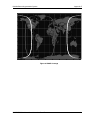
9
SUPERSTAR ................................................................................................................................ 12
Basic SUPERSTAR Setup ............................................................................................................ 13
One-Shot Alignment Mode Configuration...................................................................................... 42
Modulated GPS Data (Doppler Present) ....................................................................................... 47
Demodulated GPS Data (Doppler Present) .................................................................................. 47
The SBAS Concept ....................................................................................................................... 56
SV Deselection.............................................................................................................................. 57
SBAS Status.................................................................................................................................. 58
WAAS Coverage ........................................................................................................................... 59
5
SUPERSTAR Additional User Information Rev 0B
Tables
1
2
3
4
5
6
7
8
9
10
11
12
13
14
15
16
17
18
Use of Discretes ........................................................................................................................... 17
Discretes IP2 and IP3 functions ................................................................................................... 17
Message Summary ...................................................................................................................... 19
Field Types ................................................................................................................................... 19
List of Input Messages on Primary Communications Port ........................................................... 24
Message Summary ...................................................................................................................... 25
List of Output Messages on Primary Communications Port ......................................................... 31
Top View of 20-Pin Connector on the SUPERSTAR ................................................................... 37
Time Estimator Status Conditions ................................................................................................ 40
TRAIM Solution Status Conditions ............................................................................................... 41
1PPS and Binary Messages ........................................................................................................ 43
1PPS and Timing Binary Messages ............................................................................................. 43
1PPS and Message ID# 20 .......................................................................................................... 44
1PPS and NMEA Messages ........................................................................................................ 44
Clock Drift (CD) Effects ................................................................................................................ 48
Measurement Bits ........................................................................................................................ 49
SBAS Satellite Identification ......................................................................................................... 58
Updating Parameters ................................................................................................................... 60
SUPERSTAR Additional User Information Rev 0B
6
Software License
Software License
BY INSTALLING, COPYING, OR OTHERWISE USING THE SOFTWARE PRODUCT, YOU AGREE TO BE
BOUND BY THE TERMS OF THIS AGREEMENT. IF YOU DO NOT AGREE TO THE TERMS OF THIS
AGREEMENT, DO NOT INSTALL, COPY OR USE THE SOFTWARE PRODUCT.
1.
2.
3.
4.
5.
License: NovAtel Inc. ("NovAtel") grants you a non-exclusive, non-transferable license (not a sale) to use
one copy of the enclosed NovAtel software on a single computer, and only with the product it was supplied
with. You agree not to use the software for any purpose other than the due exercise of the rights and
licences hereby agreed to be granted to you.
Copyright: NovAtel owns, or has the right to sublicense, all copyright, trade secret, patent and other
proprietary rights in the software and the software is protected by national copyright laws, international
treaty provisions and all other applicable national laws. You must treat the software like any other
copyrighted material except that you may either (a) make one copy of the software solely for backup or
archival purposes, the media of said copy shall bear labels showing all trademark and copyright notices
that appear on the original copy, or (b) transfer the software to a single hard disk provided you keep the
original solely for backup or archival purposes. You may not copy the product manual or written materials
accompanying the software. No right is conveyed by this Agreement for the use, directly, indirectly, by
implication or otherwise by Licensee of the name of NovAtel, or of any trade names or nomenclature used
by NovAtel, or any other words or combinations of words proprietary to NovAtel, in connection with this
Agreement, without the prior written consent of NovAtel.
Patent Infringement: NovAtel shall not be liable to indemnify the Licensee against any loss sustained by it
as the result of any claim made or action brought by any third party for infringement of any letters patent,
registered design or like instrument of privilege by reason of the use or application of the software by the
Licensee or any other information supplied or to be supplied to the Licensee pursuant to the terms of this
Agreement. NovAtel shall not be bound to take legal proceedings against any third party in respect of any
infringement of letters patent, registered design or like instrument of privilege which may now or at any
future time be owned by it. However, should NovAtel elect to take such legal proceedings, at NovAtel's
request, Licensee shall co-operate reasonably with NovAtel in all legal actions concerning this license of
the software under this Agreement taken against any third party by NovAtel to protect its rights in the
software. NovAtel shall bear all reasonable costs and expenses incurred by Licensee in the course of cooperating with NovAtel in such legal action.
Restrictions: You may not: (1) copy (other than as provided for in paragraph 2), distribute, transfer, rent,
lease, lend, sell or sublicense all or any portion of the software; (2) modify or prepare derivative works of
the software; (3) use the software in connection with computer-based services business or publicly display
visual output of the software; (4) transmit the software over a network, by telephone or electronically using
any means; or (5) reverse engineer, decompile or disassemble the software. You agree to keep confidential
and use your best efforts to prevent and protect the contents of the software from unauthorized disclosure
or use.
Term and Termination: This Agreement and the rights and licences hereby granted shall continue in force
in perpetuity unless terminated by NovAtel or Licensee in accordance herewith. In the event that the
Licensee shall at any time during the term of this Agreement: i) be in breach of its obligations hereunder
where such breach is irremediable or if capable of remedy is not remedied within 30 days of notice from
NovAtel requiring its remedy; or ii) be or become bankrupt or insolvent or make any composition with its
creditors or have a receiver or manager appointed of the whole or any part of its undertaking or assets or
(otherwise as a solvent company for the purpose of and followed by an amalgamation or reconstruction
hereunder its successor shall be bound by its obligations hereunder) commence to be wound up; or iii) be
acquired or otherwise come under the direct or indirect control of a person or persons other than those
controlling it, then and in any event NovAtel may forthwith by notice in writing terminate this Agreement
together with the rights and licences hereby granted by NovAtel. Licensee may terminate this Agreement
by providing 30 days prior written notice to NovAtel. Upon termination, for any reasons, the Licensee
shall promptly, on NovAtel's request, return to NovAtel or at the election of NovAtel destroy all copies of
any documents and extracts comprising or containing the software. The Licensee shall also erase any
copies of the software residing on Licensee's computer equipment. Termination shall be without prejudice
to the accrued rights of either party, including payments due to NovAtel. This provision shall survive
termination of this Agreement howsoever arising.
SUPERSTAR Additional User Information Rev 0B
7
Software License
6.
Warranty: For 90 days from the date of shipment, NovAtel warrants that the media (for example, compact
disk) on which the software is contained will be free from defects in materials and workmanship. This
warranty does not cover damage caused by improper use or neglect. NovAtel does not warrant the contents
of the software or that it will be error free. The software is furnished "AS IS" and without warranty as to
the performance or results you may obtain by using the software. The entire risk as to the results and
performance of the software is assumed by you.
7. Indemnification: NovAtel shall be under no obligation or liability of any kind (in contract, tort or
otherwise and whether directly or indirectly or by way of indemnity contribution or otherwise howsoever)
to the Licensee and the Licensee will indemnify and hold NovAtel harmless against all or any loss,
damage, actions, costs, claims, demands and other liabilities or any kind whatsoever (direct, consequential,
special or otherwise) arising directly or indirectly out of or by reason of the use by the Licensee of the
software whether the same shall arise in consequence of any such infringement, deficiency, inaccuracy,
error or other defect therein and whether or not involving negligence on the part of any person.
8. For software UPDATES and UPGRADES, and regular customer support, contact the NovAtel GPS
Hotline at 1-800-NOVATEL (U.S. or Canada only), or 403-295-4900, or fax 403-295-4901, e-mail to
[email protected], visit our website http://www.novatel.ca or write to:
NOVATEL INC.
CUSTOMER SERVICE DEPT.
1120 - 68 AVENUE NE,
CALGARY, ALBERTA, CANADA T2E 8S5
9. Disclaimer of Warranty and Limitation of Liability:
a. THE WARRANTIES IN THIS AGREEMENT REPLACE ALL OTHER WARRANTIES, EXPRESS OR IMPLIED, INCLUDING ANY WARRANTIES OF MERCHANTABILITY OR FITNESS FOR A PARTICULAR PURPOSE. NovAtel DISCLAIMS AND EXCLUDES ALL
OTHER WARRANTIES. IN NO EVENT WILL NovAtel's LIABILITY OF ANY KIND INCLUDE ANY SPECIAL, INCIDENTAL OR CONSEQUENTIAL DAMAGES, INCLUDING
LOST PROFITS, EVEN IF NovAtel HAS KNOWLEDGE OF THE POTENTIAL LOSS OR
DAMAGE.
a. NovAtel will not be liable for any loss or damage caused by delay in furnishing the software or any
other performance under this Agreement.
a. NovAtel's entire liability and your exclusive remedies for our liability of any kind (including liability for negligence) for the software covered by this Agreement and all other performance or nonperformance by NovAtel under or related to this Agreement are to the remedies specified by this
Agreement.
THIS AGREEMENT IS GOVERNED BY THE LAWS OF THE PROVINCE OF ALBERTA, CANADA. EACH
OF THE PARTIES HERETO IRREVOCABLY ATTORNS TO THE JURISDICTION OF THE COURTS OF THE
PROVINCE OF ALBERTA.
8
SUPERSTAR Additional User Information Rev 0B
Warranty Policy
Warranty Policy
NovAtel Inc. warrants that its Global Positioning System (GPS) products are free from defects in materials and
workmanship, subject to the conditions set forth below, for the following periods of time:
SUPERSTAR Receivers
GPSAntenna™ Series
Cables and Accessories
Software Support
One (1) Year
One (1) Year
Ninety (90) Days
One (1) Year
Date of sale shall mean the date of the invoice to the original customer for the product. NovAtel’s responsibility respecting
this warranty is solely to product replacement or product repair at an authorized NovAtel location only.
Determination of replacement or repair will be made by NovAtel personnel or by technical personnel expressly authorized
by NovAtel for this purpose.
THE FOREGOING WARRANTIES DO NOT EXTEND TO (I) NONCONFORMITIES, DEFECTS OR
ERRORS IN THE PRODUCTS DUE TO ACCIDENT, ABUSE, MISUSE OR NEGLIGENT USE OF
THE PRODUCTS OR USE IN OTHER THAN A NORMAL AND CUSTOMARY MANNER, ENVIRONMENTAL CONDITIONS NOT CONFORMING TO NOVATEL’S SPECIFICATIONS, OR FAILURE TO FOLLOW PRESCRIBED INSTALLATION, OPERATING AND MAINTENANCE
PROCEDURES, (II) DEFECTS, ERRORS OR NONCONFORMITIES IN THE PRODUCTS DUE TO
MODIFICATIONS, ALTERATIONS, ADDITIONS OR CHANGES NOT MADE IN ACCORDANCE
WITH NOVATEL’S SPECIFICATIONS OR AUTHORIZED BY NOVATEL, (III) NORMAL WEAR
AND TEAR, (IV) DAMAGE CAUSED BY FORCE OF NATURE OR ACT OF ANY THIRD PERSON,
(V) SHIPPING DAMAGE; OR (VI) SERVICE OR REPAIR OF PRODUCT BY THE DEALER WITHOUT PRIOR WRITTEN CONSENT FROM NOVATEL. IN ADDITION, THE FOREGOING WARRANTIES SHALL NOT APPLY TO PRODUCTS DESIGNATED BY NOVATEL AS BETA SITE TEST
SAMPLES, EXPERIMENTAL, DEVELOPMENTAL, PREPRODUCTION, SAMPLE, INCOMPLETE
OR OUT OF SPECIFICATION PRODUCTS OR TO RETURNED PRODUCTS IF THE ORIGINAL
IDENTIFICATION MARKS HAVE BEEN REMOVED OR ALTERED. THE WARRANTIES AND
REMEDIES ARE EXCLUSIVE AND ALL OTHER WARRANTIES, EXPRESS OR IMPLIED, WRITTEN OR ORAL, INCLUDING THE IMPLIED WARRANTIES OF MERCHANTABILITY OR FITNESS FOR ANY PARTICULAR PURPOSE ARE EXCLUDED. NOVATEL SHALL NOT BE LIABLE
FOR ANY LOSS, DAMAGE, EXPENSE, OR INJURY ARISING DIRECTLY OR INDIRECTLY OUT
OF THE PURCHASE, INSTALLATION, OPERATION, USE OR LICENSING OR PRODUCTS OR
SERVICES. IN NO EVENT SHALL NOVATEL BE LIABLE FOR SPECIAL, INDIRECT, INCIDENTAL OR CONSEQUENTIAL DAMAGES OF ANY KIND OR NATURE DUE TO ANY CAUSE.
There are no user serviceable parts in the GPS receiver and no maintenance is required. When the status code indicates that
a unit is faulty, replace with another unit and return the faulty unit to NovAtel Inc.
Before shipping any material to NovAtel or Dealer, please obtain a Return Material Authorization (RMA)
number by calling NovAtel Customer Service at 1-800-NOVATEL in North America or 1-403-295-4900
elsewhere.
Once you have obtained an RMA number, you will be advised of proper shipping procedures to return any defective
product. When returning any product to NovAtel, please return the defective product in the original packaging to avoid
shipping damage.
9
SUPERSTAR Additional User Information Rev 0B
Customer Service
Customer Service
Contact Information
If you have any questions or concerns regarding your SUPERSTAR, please contact NovAtel Customer Service
using any one of the following methods:
NovAtel GPS Hotline:
1-800-NOVATEL (North America)
403-295-4900 (International)
Fax:
403-295-4901
E-mail:
[email protected]
Website:
www.novatel.com
Write:
NovAtel Inc. Customer Service Dept.
1120 - 68 Avenue NE
Calgary, Alberta, Canada
T2E 8S5
Before contacting NovAtel Customer Service regarding software concerns, please do the following:
1. Issue the NVM Reset command, ID #99.
2. Log the following data requests to a file on your PC for 30 minutes
Receiver Status, ID# 49
Ephemeris Data, ID# 22
Measurement Block, ID# 23
HW/SW Identification, ID# 45
one shot
continuous
1 Hz
one shot
3. Send the file containing the log to NovAtel Customer Service, using either the NovAtel ftp site at ftp://
ftp.novatel.ca/incoming or the [email protected] e-mail address.
Firmware Updates
Firmware updates are firmware revisions to an existing model, which improves basic functionality of the GPS
receiver. See also Appendix F, Updating Receiver Firmware on Page 60.
If you need further information, please contact NovAtel using one of the methods given above.
SUPERSTAR Additional User Information Rev 0B
10
Foreword
Foreword
Congratulations!
Thank you for purchasing a SUPERSTAR receiver. Whether you have purchased a stand alone GPS card, a
packaged receiver or a development kit, you will have received other companion documentation.
Scope
This document provides information on the SUPERSTAR GPS OEM board P/N 220-604061-XXX and 245604061-XXX. The following sections describe functionality, mechanical and electrical characteristics of the
SUPERSTAR board. This manual provides the major differences to the ALLSTAR User’s Manual intended for
P/N 220-600944-0XX. There are also additional appendices on timing, measurements and updates.
SUPERSTAR Additional User Information Rev 0B
11
Chapter 1
Introduction
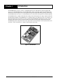
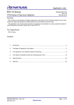
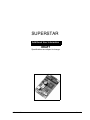
The SUPERSTAR, see Figure 1 below, is a breakthrough in low cost and small-size superior quality GPS
receivers for embedded applications. The SUPERSTAR is similar to the highly popular ALLSTAR high-end
OEM Receiver and has kept the same robust signal tracking and unsurpassed tracking capability under foliage.
The SUPERSTAR is the only low cost GPS OEM Receiver on the market offering sub-meter DGPS capability.
The SUPERSTAR is a complete GPS OEM sensor that provides 3D navigation on a single compact board with
full differential capability. The SUPERSTAR is a 12-channel GPS receiver that tracks all-in view satellites. It is
fully autonomous in the sense that once power is applied, the SUPERSTAR automatically searches, acquires
and tracks GPS satellites. When a sufficient number of satellites are tracked with valid measurements, the
SUPERSTAR produces 3D position and velocity output with an associated figure-of-merit (FOM). Please refer
to Chapter 2 of the ALLSTAR User’s Guide for more details on the FOM.
Figure 1: SUPERSTAR
12
SUPERSTAR Additional User Information Rev 0B
Chapter 2
2.1
Installation
Quick Start
This quick start section provides the basic information you need to setup and begin using your new
SUPERSTAR GPS card. For more detailed information on the installation and operation of your receiver,
please refer to the user manuals provided.
2.1.1
Additional Equipment Required
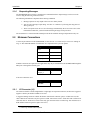
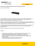
Additional user-supplied equipment needed for a basic setup (see also Figure 2) is listed below:
A Windows-based PC with an RS-232 DB-9 port
A 5 V power supply capable of providing at least 1.2 W
An enclosure to protect against environmental conditions and RF interference
A wiring harness to provide power to the receiver and access to the data and strobe signals, with
one or more DB-9 connectors for serial communication with a PC or other data communications
equipment
A straight serial cable
A quality GPS antenna
An antenna RF cable with a BNC female connector at the receiver end
Figure 2: Basic SUPERSTAR Setup
Coaxial cable from
antenna to STARBOX
Spare COM connector
Antenna
STARBOX
25-pin connector to STARBOX
9-pin connector to PC
12 V Adaptor
PC
To 120 V DC
Figure Note:
The SUPERSTAR Development Kit comes with a plastic enclosure or STARBOX, +12dB active GPS antenna,
magnetic mount, 6 meter RF cable, DB-9 cable for PC connection, automotive adapter plug and an AC to DC adaptor.
13
SUPERSTAR Additional User Information Rev 0B
Chapter 2
2.1.2
Installation
Setting Up Your SUPERSTAR GPS Card
Complete the steps below to connect and power your SUPERSTAR GPS card. Refer to the ALLSTAR User’s
Manual and this manual for more information on steps 1 through 3.
1. Install the GPS card and the wiring harness in a secure enclosure to reduce environmental
exposure and RF interference, making sure to protect against ESD. If you do not take the necessary
precautions against ESD, including using an ESD wrist strap, you may damage the card.
2. Mount the GPS antenna on a secure, stable structure with an unobstructed view of the sky.
3. Connect the GPS antenna to the receiver using the antenna RF cable.
4. Connect a serial port on the receiver to a serial port on the PC using a null modem cable.
5. Connect the power supply to the receiver.
6. Plug in and/or turn on the power supply.
2.1.3
Installing StarView
Once the receiver is connected to the PC, antenna, and power supply, install the StarView software. The StarView
CD is supplied with the development kits, otherwise StarView is available on our website.
From CD:
1. Start up the PC.
2. Insert the StarView CD in the CD-ROM drive of the computer.
3. Install the StarView software and follow the steps on the screen. If the setup utility is not
automatically accessible when the CD is inserted, select Run from the Start menu and press the
Browse button to locate Setup.exe on the CD drive.
From our website:
1. Start up the PC and launch your internet service program.
2. Go to our website and download the StarView setup program.
3. Select Run from the Start menu and press the Browse button to locate Setup.exe. The default
location is in the C:/Program Files/Starview directory.
4. Click on the OK button to install the StarView software and follow the steps on the screen.
2.1.4
Establishing Communication with the Receiver
To open a serial port to communicate with the receiver, complete the following.
1. Launch StarView from the Start menu folder specified during the installation process. The default
location is Start | Programs | StarView.
2. Open the File/Port menu and select Auto Connect.
The default baud rate is 9600 baud unless your receiver has the Carrier Phase Output option (19200 baud).
2.1.5
Using StarView
StarView provides access to key information about your receiver and its position. The information is displayed
in windows accessed from the Window menu. For example, select Navigation/LLH Solution from the Window
menu to display the position of the receiver in LLH (latitude, longitude and height) coordinates. To show
details of the GPS satellites being tracked, select Satellites/Status from the Window menu.
14
SUPERSTAR Additional User Information Rev 0B
Installation
2.1.6
Chapter 2
Requesting Messages
The SUPERSTAR GPS card uses a comprehensive command interface. Input messages can be sent to the
receiver using the Xmit Msg menu in StarView.
The following information is important when entering commands:
1. Message requests are only output to the receiver in binary format.
2. You can send a message request using ‘one shot’ or ‘continuos’ by selecting Xmit Msg/General
Message Request.
3. There is an option in StarView to save all messages transmitted by the receiver into a file. Select
File/Port/Save Data after you have finished selecting messages in Step #2 above.
The ALLSTAR User’s Manual and this manual provide all the available messages and parameters they use.
2.2
Minimum Connections
J1 is the 20-pin connector on the SUPERSTAR, see also Section A.4, 20 Pin Interface Connector starting on
Page 37. The minimum number of connections on J1 required for the system to operate:
Signal Name
J1 Pin #
VCC
2
Ground
10, 13, 16 & 18
TX_No_1
11
RX_No_1
12
If DGPS corrections are required for the application, they may be transmitted to the SUPERSTAR through the
Main port or through the Auxiliary port:
Signal Name
RX_No_2
J1 Pin #
15
If an active antenna is used:
Signal Name
PREAMP
2.2.1
J1 Pin #
1
I/O Connector (J1)
The connector shall be a 2mm straight header or right angle 2x10 position connector, PN from one suggested
supplier is Samtec part number: TMM-110-03-T-D.
A suggested mating connector could be the Samtec 2mm female connector (part no. TCSD-10-01-N). The
cable could also be ordered as one piece (part no. TCSD-10-D-2.00-01-N for a 2î flat cable with a connector at
each end). Part no. TCSD-10-S-12.0-01-N has only one connector and is 12 inches long. You could also use a
PCB mounted connector (part no. SQT-110-01-L-D1).
1. 0.340" long standoffs will be required
SUPERSTAR Additional User Information Rev 0B
15
Chapter 2
Installation
The latest connector specifications can be obtained from Samtec or other equivalent manufacturers.
2.2.2
RF Connector (J2)
The standard RF connector is a straight MCX jack connector. A right angle MCX connector is offered as an
option.
Suggested supplier:
On-Board connector:
Johnson Comp
133-3701-211
Interface between SUPERSTAR and customer application:
Suggested Supplier:
Supplier part number:
Omni Spectra
5831-5001-10
or
Suggested Supplier:
Supplier part number:
Suhner
11MCX-50-2-10C
or
Suggested Supplier:
Supplier part number:
Radiall
R113082.
The center conductor will provide power for an active antenna (PREAMP signal from J1-1).
2.3
Power Requirements
See also Appendix A, Technical Specifications, starting on Page 33.
2.3.1
Antenna
The maximum operating voltage for an active antenna supply (PREAMP) is 12 Volts.
2.3.2
Input Voltage
VCC is the main and unique power source for normal operation with a maximum operating voltage of 5.5
Volts.
2.3.3
Memory Back-Up
The SUPERSTAR has a supercap device allowing a warm start, where the receiver has an approximate
position, an approximate time and a valid almanac, without the need of an external power supply during a
power-off state. VBATT is an external back-up source for the time keeping circuit.
A warm start is available for 1 week typically (25∞C) and 3 days over a more extreme temperature range (-30 to
+75∞C). Therefore, VBATT can be used to extend the time retention period.
An external series diode will be required between J1-3 and the external power source to prevent the
supercap from discharging into your circuitry.
16
SUPERSTAR Additional User Information Rev 0B
Installation
2.4
Chapter 2
Protocol Selection and Non Volatile Memory
Discrete IOs are available with a SUPERSTAR Development Kit and are useful if you have Application
Program Interface (API) software. A summary is shown in Table 1 below.
Table 1: Use of Discretes
Discrete Name
Development KIT
Equivalent Name
GPIO2
IO1
Navigator
IN/OUT
GPIO3
IO2
SP
IN/OUT
GPIO5
IP1
GPS Data
IN/OUT
GPIO6
IP2
NVM Control
IN/OUT
GPIO7
IP3
Protocol Select
IN/OUT
Use
Direction
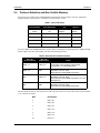
If you use NMEA, the SUPERSTAR offers you the option of setting the I/O operating mode to NMEA through
discrete input levels. Disc_IP2 and Disc_IP3 have the following functions:
Table 2: Discretes IP2 and IP3 functions
Disc_IP3
(Protocol Select)
Disc_IP2
(NVM Control)
Result
OPEN - HI
OPEN - HI
Configuration stored in NVM or Default ROM
Configuration if no valid NVM elements
OPEN - HI
GND
Protocol on Port #1: Binary
Baud Rate on Port #1: 9600
Other elements: Default ROM Configuration
GND
OPEN - HI
Protocol on Port #1: NMEA
Baud Rate on Port #1: 4800
Other elements: Default ROM Configuration if no valid
NVM elements
GND
GND
Protocol on Port #1: NMEA
Baud Rate on Port #1: 4800
Other elements: Default ROM Configuration
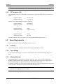
Discrete inputs can also be viewed in byte 26 of Message ID# 49, Receiver Status Data (refer to the ALLSTAR
User’s Manual) as follows:
Bit#
Description
0
DISC_IP1
1
DISC_IP2
2
DISC_IP3
3
DISC_IO1
4
DISC_IO2
5
DISC_IO3
6-7
Reserved
SUPERSTAR Additional User Information Rev 0B
17
Chapter 2
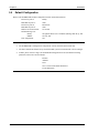
2.5
Installation
Default Configuration
Below is the SUPERSTAR’s default configuration with no valid NVM elements:
Protocol on port #1:
Baud Rate on port #1:
Protocol on port #2:
Baud Rate on port #2:
DGPS Correction Timeout:
Default Message List:
Binary:
NMEA:
Time Align Mode:
1.
Binary
9600
RTCM-104
9600
45 seconds
Navigation Status User Coordinates (Message ID# 20) @ 1Hz
GGA @ 1Hz
ON
Time Align Mode was set to OFF for the ALLSTAR
2.
The SUPERSTAR is configured in 1 Hz position, velocity, and time (PVT) mode only.
3.
The data contained in NVM is always used if the DISC_IP2 is left unconnected or tied to HI logic.
4.
If DISC_IP2 is tied to LO logic, the default ROM configuration will be used and the following
parameters will not be read from NVM:
Position
Almanac
Time
UTC Correction and IONO Parameters
TCXO Parameters
18
SUPERSTAR Additional User Information Rev 0B
Chapter 3
Input Messages
This section contains messages that have a difference in the Binary protocol between the ALLSTAR and
SUPERSTAR OEM boards.
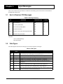
3.1
Host to Receiver CPU Messages
Table 3: Message Summary
ID
DEFINITION
MESSAGE TYPE
# BYTES
2
Reset Receiver
CM
14
69
Set Timing Parameters
CM
33
80
Set Position/Operating Mode
CM
38
90
Satellite Deselection
CM
18
103
Set Date, Time & GPS Time Alignment Mode
CM
21
113
Request Timing Information
DR
6
LEGEND:
CM: Command Message
DR: Data Request
3.2
Field Types
The following table describes the field types used in the description of messages.
Table 4: Field Types
Binary Size
(bytes)
Description
Char
1
UChar
Short
UShort
Long
1
2
2
4
ULong
4
Double
8
Float
4
Hex
n
The char type is an 8-bit integer. Values are in the range -128 to +127. This integer value
may be the ASCII code corresponding to the specified character.
The same as Char except that it is not signed. Values are in the range from +0 to +255.
The short type is 16-bit integer in the range -32768 to +32767.
The same as Short except that it is not signed. Values are in the range from +0 to +65535.
The long type is 32-bit integer in the range -2147483648 to +2147483647.
The same as Long except that it is not signed. Values are in the range from +0 to
+4294967295.
The double type contains 64 bits: 1 for sign, 11 for the exponent, and 52 for the mantissa.
Its range is ±1.7E308 with at least 15 digits of precision. This is IEEE 754.
The float type contains 32 bits: 1 for the sign, 8 for the exponent, and 23 for the mantissa.
Its range is ±3.4E38 with at least 7 digits of precision. This is IEEE 754.
Hex is a packed, fixed length (n) array of bytes in binary but in ASCII or Abbreviated
ASCII is converted into 2 character hexadecimal pairs.
Type
19
SUPERSTAR Additional User Information Rev 0B
Chapter 3
3.3
Input Messages
Message Content - Host CPU to Receiver
3.3.1
Reset Receiver ID# 2
This command resets the SUPERSTAR receiver.
BYTE
1-4
5-12
20
BIT
DESCRIPTION
UNITS
TYPE
Header, refer to Section V of the ALLSTAR User’s Manual
Password
UGPS-000 In ASCII format, U character first.
ns
Uchar[8]
SUPERSTAR Additional User Information Rev 0B
Input Messages
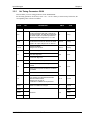
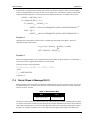
3.3.2
Chapter 3
Set Timing Parameters ID# 69
This will allow you to set timing parameters for the SUPERSTAR.
Set the timing parameters. If all ones (F..FFh = 1111...11111111 binary) is entered in any field below, the
corresponding value will not be modified.
BYTE
1-4
BIT
DESCRIPTION
UNITS
TYPE
Header, refer to Section V of the ALLSTAR User’s Manual
5-8
Cable Delay
Set the propagation delay that is induced by
the antenna cable. This delay will compensate
the 1PPS output so it remains synchronized
with the UTC time. Range from -1 to +1 ms
ns
Long
9-12
1PPS Offset
Set the offset from the UTC time for the 1PPS
signal to be output. Range from 0 to 900 ms
100 ms
Ulong
13-16
1PPS Pulse Width
Range from 0 to 65 ms
100 ns
Ulong
N/A
Char
N/A
Char
19
TRAIM Alarm Limit
Time solution error threshold at which the
alarm limit will be raised.
Range from 0 to 2.55 ms
0 indicates no TRAIM is to be performed.
10 ns
Uchar
20-21
Intrinsic delay Range from 0 to 65534 ns
65535 ns indicates no changes.
ns
Uword
17
0
Standard Timing Mode
1
One Shot Alignment
2
Continuous Alignment
0
1PPS Output continuously
1
1PPS Output only when tracking at least one
satellite
2
1PPS Output only when an alarm is not raised
by TRAIM
3
Conditions 1 and 2 above
18
22-23
24-27
Word
Reserved
28-31
SUPERSTAR Additional User Information Rev 0B
N/A
Long
Long
21
Chapter 3
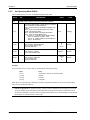
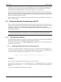
3.3.3
Input Messages
Set Operating Mode ID# 80
This command allows you to set the SUPERTSTAR operating mode.
BYTE
1-4
BIT
DESCRIPTION
UNITS
TYPE
Header, refer to Section V of the ALLSTAR User’s Manual
5-12
Password (UGPS-XXX), in ASCII format, U character
first, where the command field XXX:
000 - Set User Position (ALLSTAR compatible, see
below)
R00 - Force to Rover Mode (position not saved)
GSP - Get Survey Position
BYY - Set Base Position and Base Information
SYY - Force to Survey Mode where
YY: bytes 11..12 (Station ID and Station Health)
bits 0..9 : Station ID (10 bits:1-1023)
bits 10..12 : Station Health (as per RTCM-104)
bits 13..15: Reserved
13-20
Interpretation depends on the command field XXX.
000 and BYY: Altitude Ellipsoid
SYY: Desired Survey Time
R00 and GSP: N/A
21-28
Interpretation depends on the command field XXX.
000 and BYY: Latitude
SYY, R00 and GSP: N/A
29-36
Interpretation depends on the command field XXX.
000 and BYY: Longitude
SYY: Desired CEP
R00 and GSP: N/A
N/A
m
or
hours
radians
radians
or
m
Char [8]
Double
Double
Double
Example:
You can set the receiver in static mode by assembling the following message:
Bytes
[5-12]
[13-20]
[21-28]
[29-36]
Entry
UGPS-BYY | Station ID | Station Health
Altitude
Latitude
Longitude
When the receiver decodes this command, the latitude, longitude and altitude are saved in its NVM and the
static mode is initiated immediately.
Self-Surveying Mode: On certain occasions, you may wish to terminate the surveying process. You can
do this by using the GSP command as indicated in the message specification above. When the receiver
decodes this command, it uses the current averaged position and saves it to NVM without a station ID and
Health Status. It will then switch to static mode.
22
SUPERSTAR Additional User Information Rev 0B
Input Messages
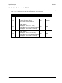
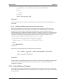
3.3.4
Chapter 3
Satellite Deselection ID# 90
This command deselects the desired SVs if the password is valid. The SVs to deselect are indicated in a bitmap
form. A 1 in the bitmap specifies that the corresponding SV will be deselected.
BYTE
1-4
BIT
DESCRIPTION
UNITS
TYPE
Header, refer to Section 5 of the ALLSTAR User’s Manual
5-12
Password (UGPS-XXX), in ASCII format, U
character first where XXX is:
000 - Deselect GPS SV
0G4 or 0G5 - Deselect WAAS SV
N/A
Char[8]
13-14
[000] - GPS SV
bit map (bit 0 - SV #1, bit 7 - SV #8)
bit map (bit 0 - SV #9, bit 7 - SV #16)
[0G5] - SBAS SV (such as WAAS or EGNOS)
bit map (bit 0 - SV #129, bit 7 - SV #136)
bit map (bit 0 - SV #137, bit 7 - SV #138)
N/A
N/A
15-16
[000] - GPS SV
bit map (bit 0 - SV #17, bit 7 - SV #24)
bit map (bit 0 - SV #25, bit 7 - SV #32)
[0G4] - SBAS SV (such as WAAS or EGNOS)
bit map (bit 0 - SV #129, bit 7 - SV #136)
bit map (bit 0 - SV #137, bit 7 - SV #138)
N/A
N/A
SUPERSTAR Additional User Information Rev 0B
23
Chapter 3
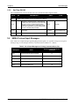
3.3.5
Input Messages
Set Time ID# 103
This command allows you to set the date, time (UTC) and the GPS Time Alignment mode.
BYTE
1-4
3.4
BIT
DESCRIPTION
UNITS
TYPE
Header, refer to Section V of the ALLSTAR User’s Manual
5-12
Password, in ASCII format, U character first
UGPS-000: Sets system time to provided date
& time if no SV is currently being tracked.
UGPS-100: Requests a 1-shot 1PPS output,
and sets system time to provided date & time if
no SV is currently being tracked.
N/A
Char[8]
13-15
UTC time
h:min:s
Uchar:Uchar:Uchar
16-19
UTC date
dy:mo:yr
Uchar:Uchar:Ushort
NMEA Protocol Input Messages
Table 5 lists a set of input messages supporting Waypoint Navigation, see Appendix D, Waypoint Navigation,
starting on Page 53. The message contents are described in the ALLSTAR User’s Manual.
Table 5: List of Input Messages on Primary Communications Port
Message ID
24
Sentence Length (Maximum) Characters
Name
000
Configure Primary Port Command
17
001
Initialization Data Command
77
005
Set Output Configuration Command
67
009
Define Waypoint
57
010
Select Active Waypoint
18
SUPERSTAR Additional User Information Rev 0B
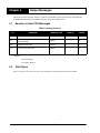
Chapter 4
Output Messages
This section contains messages that have a difference in the Binary protocol between the ALLSTAR and
SUPERSTAR OEM boards. The NMEA protocol is identical for both products.
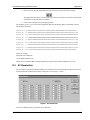
4.1
Receiver to Host CPU Messages
Table 6: Message Summary
ID
DEFINITION
MESSAGE TYPE
RATE (/s)
# BYTES
23
Measurement Block
UR/FR
variable
variable
67
SBAS (for example WAAS and EGNOS)
Current Message
UR/FR
1
54
68
SBAS Message Status
UR/FR
1
13
113
Precise Timing information
UR/FR
1
65
LEGEND:
FR: First Request
UR: Update Request
4.2
Field Types
Please see Table 4, Field Types on Page 19 for descriptions of the field types used in this manual.
25
SUPERSTAR Additional User Information Rev 0B
Chapter 4
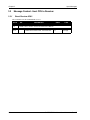
4.3
Output Messages
Binary Message Content - Receiver to Host CPU
4.3.1
Measurement Block ID# 23
This message contains raw data carrier and code, and the parameters required for all applications. The total
length of the message is
15 + 11*N Measurement Block + 2
Please also read the Measurements appendix starting on Page 46 of this manual for more details on raw
code phase measurements and raw carrier phase measurements.
BYTE
1-4
BIT
DESCRIPTION
UNITS
TYPE
Header, refer to Section 5 of the ALLSTAR User’s Manual
OFFSET
0
5
Slew Value
ns
Char
4
6
Reserved
N/A
N/A
5
7
Number of Measurement Blocks
Uchar
6
8..15
Predicted GPS Time
This is the time when the measurement
samples have been taken at the receiver. Not
to be confused with the transmission time.
seconds
Double
7
N/A
N/A
15
16
0-5
SV Number
6
Reserved
7
Toggle at each ephemeris transmission
17
Signal-to-Noise ratio (SNR). For example, a
value of 160 will translate to 40.0 dB/Hz
0.25 dB/Hz
Uchar
16
18..21
Code Phase
The correlator will align the locally generated
satellite C/A with the received signal using a
precision of 1/1024 of a half chip. A chip lasts
for 1/1023 ms Therefore, the code phase
precision is 1/1023 ms/2/1024.
range: 0.. 2095103999
1/1024 half
chip
Ulong
17
Continued on Page 27
26
SUPERSTAR Additional User Information Rev 0B
Output Messages
Chapter 4
Carrier Phase
bit 0-1: SUPERSTARs/ALLSTAR
Value 0: Ready
Value 1: Phase Unlock
Value 2: Cycle Slip Detected
Value 3: Not Ready
0-1
22..25
bit 0-1: Base RTCM
Value 0: Ready
Value 1: Carrier not sync
Value 2: Phase Unlock
Value 3: Bit ambiguity not resolved
N/A
N/A
21
For most applications, use measurements only
when both bits 0 and 1 are clear. See Section
C.4, Carrier Phase In Message ID# 23 starting
on Page 49.
2-31
Integrated Carrier Phase
Cycle_Slip Counter. Raw data and tracking
loop slips will be observable in the
measurement. The carrier tracking loop has a
180 degrees ambiguity so it is possible to slip
by a full cycle or a half cycle. The half cycles
will be detected and signalled through the
measurements qualifiers (least significant 2
bits of the carrier phase).
26
cycles
N/A
N/A
Uchar
25
N/A
Hex
variable
SUPERSTARs
Increment by 1 every time a cycle slip is
detected during a 10ms period
Base RTCM
Loss of Carrier continuity and number of
GPS data parity errors
27...
Next SV offset = 15 + (#SVs x 11)
CheckSum
Example Output:
Example Header Translated to Decimal: 01 23 232 110
SUPERSTAR Additional User Information Rev 0B
27
Chapter 4
4.3.2
Output Messages
SBAS Current Message ID# 67
This message is output at a nominal rate of once per second and its length is 50 bytes. It is available to anyone
with a SBAS-capable (for example WAAS and EGNOS) receiver model. Bytes 21 - 52 of this message provide
the 250 bits SBAS message. The 250-bit message is packed into a 32-byte frame. See also Section E.2.1,
Logging Message ID# 67 starting on Page 56.
BYTE
1-4
BIT
DESCRIPTION
UNITS
Type
Header, refer to Section 5 of the ALLSTAR User’s Manual
5..8
Week number
N/A
Ulong
9..16
GPS Time
s
Double
17..20
Reserved
N/A
Ulong
N/A
char [32]
N/A
Hex
0-243
SBAS message data field
244-249
Reserved
21..52
CheckSum
Example Output:
Example Header Translated to Decimal: 01 67 188 48
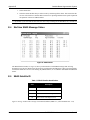
4.3.3
SBAS Message Status ID# 68
This message provides the status of the SBAS (for example WAAS and EGNOS) message and is output at a
nominal rate of once per second if your receiver is a SBAS-capable model.
BYTE
1-4
DESCRIPTION
UNITS
TYPE
Header, refer to Section 5 of the ALLSTAR User’s Manual
5-6
Message count
N/A
Ushort
7
SV Source
N/A
Char
8
SBAS message type
N/A
Char
9-11
Reserved
N/A
Hex
CheckSum
28
BIT
SUPERSTAR Additional User Information Rev 0B
Output Messages
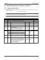
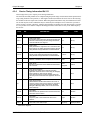
4.3.4
Chapter 4
Precise Timing Information ID# 113
This message allows you to request precise timing information.
The clock bias and drift parameters are computed using the pseudo-range measurements and the predicted true
range (using the known user position). A Time Figure-Of-Merit (TFOM) for the clock errors is derived using
the residuals of the least-square time solution. When using GPS measurements only, the TFOM does not take
into account any bias in the residuals that may be induced by the atmospheric errors. Therefore it provides a
relative accuracy estimate. Obviously, when the WAAS channel is available, the clock bias estimate is virtually
free of systematic errors and the computed TFOM approximates an absolute accuracy of the 1PPS output by
the receiver.
BYTE
1-4
BIT
DESCRIPTION
UNITS
TYPE
Header, refer to Section 5 of the ALLSTAR User’s Manual
5Ö 8
Cable Delay Value
Propagation delay induced by the antenna cable that
has been entered using the Set Timing Parameters
command ID# 69, see Page 21.
ns
Ulong
9Ö 12
1PPS Offset
Delay between the edge of the UTC second and the
rising edge of the 1PPS signal that has been entered
using the Set Timing Parameters command ID# 69.
ns
Ulong
13..16
1PPS Pulse Length
Length of the 1PPS pulse that has been entered
using the Set Timing Parameters command ID# 69.
100 ns
Ulong
17
Number of Observations
Number of satellites used to compute the clock error
N/A
Uchar
18..19
Mask Angle
Elevation angle below which satellite measurements
are not used.
0.01
degrees
Uword
20
Leap Second Change
Indicates the change to the leap second value
applicable at the end of the current day (at midnight).
Zero indicates no leap second change.
This value will revert to 0 after midnight, when the
new leap second value has been applied to the UTC
time.
s
Char
21
Leap Second Value
Offset between the GPS time and the UTC time. It
contains only the leap second number. It does NOT
contain the fractional part transmitted in the GPS
Navigation Message ID#21 (refer to the ALLSTAR
User’s Manual).
s
Char
22..29
Clock Bias
Bias between the predicted time and the actual time
at the time of the solution.
ns
Double
30..37
Clock Drift
Frequency drift of the TCXO at the time of the
solution.
ppm
Double
38..41
UTC Date of the 1PPS output.
dy:mo:yr
byte:byte:Word
Continued on Page 30
SUPERSTAR Additional User Information Rev 0B
29
Chapter 4
Output Messages
42..51
UTC Time of the 1PPS output.
hr:min:s
byte:byte:Double
52..55
1PPS Residual
Residual computed from the expected 1PPS output
time and the actual 1PPS output time, within the
resolution period of ±50 ns.
To be used for systems with feedback or for postprocessing.
ns
Long
0-1
Timing Operating Mode
00: Standard
01: One shot alignment
10: Constant alignment
2-3
TRAIM Status
00:Normal
01: Fault Detected
10:Fault Isolated
11:Warning (not enough SVs)
4-5
Static Operation Status
00: Successful
01: Warning (TRAIM cannot run)
10: Not Ready (no measurements)
11: Alarm (raised by TRAIM)
6
WAAS Processing
0: Inactive
1: Active
7
Static Operation
0: Inactive
1: Active
56
57..60
ns
Long
61
TRAIM Alarm Limit
10 ns
Uchar
62..63
Intrinsic delay
ns
Uword
N/A
Hex
CheckSum
30
TFOM(1Φ) Clock Bias
Uchar
SUPERSTAR Additional User Information Rev 0B
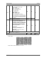
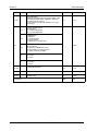
Output Messages
4.4
Chapter 4
NMEA Protocol Output Messages
Table 7 lists a set of output messages supporting Waypoint Navigation, see Appendix D, Waypoint Navigation,
starting on Page 53. The message contents are described in ALLSTAR User’s Manual, except for NMEA ID#
905 which is described in the next section of this document.
Table 7: List of Output Messages on Primary Communications Port
Message ID
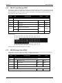
4.4.1
Name
Sentence Length
(Maximum) - Characters
900
Navigation Status
21
905
User Position ñ UTM Format
45
906
Bearing, Distance & DeltaElevation to Waypoint
87
907
User Position - MGRS Format
57
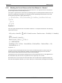
User Position in UTM Format ID# 905
Current position in UTM format and UTC time of position.
________________________________________________________________________
|
HEADER
| CONTENTS OF DATA FIELDS
|
________________________________________________________________________
$PMCAG,905 |
|
| ,xx,xxxxxx,xxxxxxx,hhmmss.ss,A*hh<CR><LF>
|
| |
|
|
|
|
|
| |
|
|
|
Status1
|
| |
|
|
UTC time of position
|
| |
|
Grid northing
|
| |
Grid easting
|
Zone number
________________________________________________________________________
1
Status:
A = Data Valid ñ Navigation Mode
B = Data Valid ñ Position Initialized
V = Data Invalid
Example:
$PMCAG,905,18,602090,5038779,141105,A*79<CR><LF>
Zone number
Easting
Northing
UTC time
Status
-
18
602090
5038779
14:11:05
Valid Data
The position references the receiver’s active datum.
SUPERSTAR Additional User Information Rev 0B
31
Chapter 4
32
Output Messages
SUPERSTAR Additional User Information Rev 0B
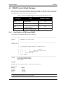
Appendix A
Technical Specifications
A.1
Dimensions
A.2
SUPERSTAR GPS Card
GENERAL CHARACTERISTICS*
12-PARALLEL ì ALL-IN-VIEWî TRACKING
L1 Frequency:
1,575.42 MHz
Minimum Tracking Sensitivity:
-135 dBm (antenna input level)
SUPERSTAR Additional User Information Rev 0B
33
Appendix A
Technical Specifications
PERFORMANCE*
Position Accuracy:
DGPS <1 m (CEP)
Single Point:
<5 m (CEP)
Time to First Fix:
Hot start: 15 s typical, with current almanac,
position, time and ephemeris
Warm start: 45 s typical, with current almanac,
position and time
Cold start: 2 min. typical, no almanac, no position
and no time
Signal Re-Acquisition:
< 1 s (typical) (5 s obscuration)
< 3 s (typical) (60 min. obscuration)
Dynamics:
Velocity:
1852 km/h (514 m/s) (limited by US and Canadian
export laws)
Acceleration:
4 Gs (39.2 m/s2)
Jerk:
2 m/s3
Altitude:
60,000 ft. (18 km)
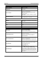
HARDWARE SPECIFICATIONS*
34
Prime Power:
5.0 +10%/-5% VDC INPUT
(50-mV p-p ripple maximum)
1.2 W at 5.0 VDC typical with passive antenna
ì Time-Keepingî Power:
2.5 to 4.5 VDC external input
<1µA (5V), <0.3µA (3V)
Supercap on-board to maintain SRAM and
time for warm start
Serial Communications:
2 x RS-232 (TTLlevel) asynchronous data ports;
TX1-RX1, TX2-RX2 9,600 baud standard (select
from 300 to 19 200 bauds)
3rd and 4th input/output ports (on special version)
Input Messages:
Rx 1: NMEA/Binary
Set altitude, position, date and time selectable
output messages and rates
Rx 2: RTCM SC-104
Message types 1, 2, 9
Output Messages:
Tx 1: NMEA, GGA, GSA, GSV, RMC, VTG,
ZDA, GLL plus proprietary messages or Binary
All data available on NMEA messages plus channel
assignments, ephemeris, Built in Test result (BIT),
others, (integrated carrier phase data optional 1 Hz)
Tx 2: Spare
SUPERSTAR Additional User Information Rev 0B
Technical Specifications
Appendix A
L1 pulse/s, aligned with GPS time (± 200 ns typical
in absolute mode)
(± 50 ns typical in relative mode), with SA imposed
Discrete: 3 general purpose input/output lines
Time Mark Output:
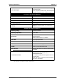
PHYSICAL AND ENVIRONMENTAL*
Dimensions:
1.8" W x 2.8" L x 0.51" H; (46 x 71 x 13 mm)
Weight:
0.05 lb. (22 g)
Operating Temperature:
-30∞C to +75∞C (standard)
Storage Temperature:
-55 to +90∞C
Humidity:
5% to 95% relative humidity, non-condensing to
+60∞C
SUPERSTAR DEVELOPMENT KIT*
Operating Voltage:
10 VDC to 16 VDC
Operating Temperature:
0∞C - 40∞C
Serial Ports:
DB-9 female RS-232 Port 1
INPUT/OUTPUT
DB-9 female RS-232 Port 1 DGPS IN
Time Mark:
4 pin right angle header
Power Connector:
2.5 mm male positive center
Antenna Connector:
BNC male with +5V supply for active antenna
3 LEDs:
Power on, time mark DGPS mode
8 DIP Switches:
Various control functions, refer to the full schematic
for details.
Accessories included:
A plastic enclosure, including a power regulator,
RS-232 driver, 3 LED indicators and a
SUPERSTAR receiver.
A +12dB active GPS antenna, magnetic mount and
6 meter cable.
DB-9 cable for PC connection, automotive adapter
plug, AC to DC adaptor.
* Specifications are subject to change without notice
SUPERSTAR Additional User Information Rev 0B
35
Appendix A
A.3
Technical Specifications
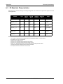
I/O Electrical Characteristics
Input pins have a valid state during reset and operating mode. No connection is required if the signal is not used
in the application.
SIGNAL
Type
Input Lo
Max V
Input Hi
MIN V
OUTPUT
Lo Max V
Output Hi
min v
Notes
MASTER_RESET
I
0.5
2.0
(1)(4)
DISC_IP_1, _2, _3
RX_No_1, _2
I
0.8
2.5
(3)(4)(6)
DISC_IO_1, _2
I/O
0.8
2.5
TX_No_1, _2
O
RX_No_3/
DISC_IO_3
I/O
TIMEMARK
TX_No_3
O
0.8
2.0
0.4
3.0
lo out≤200µA
(3),(5),(8)
0.4
3.0
lo out≤200µA
(4)
0.4
3.7
lo out≤200µA
(3),(4),(8)
0.4
3.7
lo out≤200µA
(7),(8)
Notes:
1:
2:
3:
4:
5:
6:
7:
8:
36
A LO pulse of 150ns will invoke a master reset to the SUPERSTAR (Max. 1µs rise & fall time)
Conditions: 5V +10%/-5% for all limits
Maximum input Voltage is 5.5V
All pins are in input mode during reset with pull-up resistor
All pins are in input mode during reset with pull-down resistor
DISC_IP_1 (Programming Ctrl Pin) is in input mode during reset with pull-down resistor
All pins are forced to an output logic level 0 during reset state
All outputs shall deliver a maximum current of 2mA
SUPERSTAR Additional User Information Rev 0B
Technical Specifications
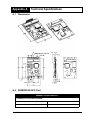
A.4
Appendix A
20 Pin Interface Connector
Table Table 8 shows connector J1 (2X10, 2mm header) on the SUPERSTAR. See also Appendix A.1,
Dimensions, starting on Page 33.
Table 8: Top View of 20-Pin Connector on the SUPERSTAR
PIN #
Pin 19
Pin 1
Pin 20
Pin 2
Signal Name
Function
1
PREAMP
Power for active antenna (40 mA max)
2
VCC
Primary power (5V +10%/-5%)
3
VBATT
Back-up power for real-time clock device (external series diode required)
4
DISC_IO_3
Programmable discrete I/O expansion pin for special applications
5
MASTER_RESET
Reset input pin (active LO)
6
DISC_IP_1
Reprogramming control input pin (active HI)
7
DISC_IP_3
Protocol select pin (see Section 2.4 on Page 17)
8
DISC_IP_2
NVM control pin (see Section 2.4 on Page 17)
9
DISC_IO_1
Programmable discrete I/O expansion pin for special applications
10
GND
Ground
11
TX_No_1
Serial port TX #1a
12
RX_No_1
Serial port RX #1 a
13
GND
Ground a
14
TX_No_2
Serial port TX #2 a
15
RX_No_2
Serial port RX #2 a
16
GND
Ground
17
DISC_IO_2
Programmable discrete I/O expansion pin for special applications
18
GND
Ground
19
TIMEMARK
1PPS (1 Pulse Per Second) output
20
Reserved
a.
Low Voltage Transistor Transistor Logic (LVTTL)
SUPERSTAR Additional User Information Rev 0B
37
Appendix B
Timing Engine and Relationships
This appendix familiarizes you with the SUPERSTAR Timing Engine option features. This GPS receiver
enables the output of a precise 1PPS (1 Pulse-Per-Second) signal aligned to UTC time, along with related
timing data. The Precise Timing feature is a factory-installed option (also known as a config block) on the GPS
receiver. Verify that the configuration part number 169-613955-010 is installed within the SUPERSTAR.
This appendix details the use of the SUPERSTAR Timing Engine from a user standpoint, that is, the
performance specifications, functional descriptions, and I/O messages.
You may also have the SBAS (for example WAAS and EGNOS) option installed separately on the
SUPERSTAR. The SBAS and Precise Timing features are independent from one another, but together yield a
more accurate 1PPS alignment and enhanced timing integrity. See also Appendix E, Satellite-Based
Augmentation System, starting on page 55.
Also, this appendix summarizes 1PPS with Binary, NMEA, and Message ID# 20 timing relationships
respectively for the SUPERSTAR.
B.1
The SUPERSTAR Timing Engine
The SUPERSTAR Timing Engine provides an accurate 1PPS timing pulse aligned to UTC for use in precise
network synchronization applications. Several timing parameters are configurable; these are detailed further.
As an option, the receiver can make use of the SBAS signal to enhance the availability, integrity and accuracy
of the timing pulse.
This receiver can operate as a standard SUPERSTAR receiver, that is, provide position, velocity and time
information in real-time under any given dynamics, or it can operate in static mode and provide an accurate
timing signal. You can set the receiver to operate in either static or dynamic mode. The receiver is also capable
of self-surveying its position.
The accuracy of the 1PPS signal, that is, the alignment of the leading edge of the 1PPS with respect to the UTC
second boundary, is as follows:
±30 ns (1σ), or ±60 ns (peak-to-peak using DGPS or WAAS corrections)
B.2
Definitions
This section gives some definitions to some fundamental timing elements presented in this appendix.
The 1PPS Output Time represents the predicted time, in UTC units, at which the 1PPS signal has been output.
This predicted time is based on a propagation of the receiver’s previously computed system time including
clock bias and clock drift.
The 1PPS Residual is simply the difference between the 1PPS Output Time and the desired output time. For
example, if the desired output time is 12:00:00.000000000 and the computed 1PPS Output Time is
12:00:00.000000025, then the 1PPS Residual is 0.000000025.
The clock bias represents the estimated error in the previous predicted time. This value is computed at the
standard receiver solution update rate and is based on the GPS measurements and the known receiver position.
The clock bias values are typically filtered to remove the intrinsic measurement noise (thermal noise,
atmospheric corrections mis-modeling, etc.). The intent is to have the clock bias represent the true oscillator’s
phase error as accurately as possible. Note that the clock bias does not represent the absolute error of the time
misalignment. For example, if there is a 10-ns offset in all pseudorange measurements, the filter tracks the best
estimate along that constant offset.
The clock drift represents the oscillator’s frequency error. This value is typically computed using the GPS
carrier phase measurements.
SUPERSTAR Additional User Information Rev 0B
38
Timing Engine and Relationships
B.3
Appendix B
Precise Timing Features
In static mode, the receiver uses a known position with the observed measurements (pseudo-ranges and deltaranges) to derive accurate clock information, that is, the clock bias and clock drift. Set the receiver in static
mode using command Message ID# 80 (see Page 22), in which the exact position of the receiver antenna must
be encoded.
The 1PPS output can be programmed to be offset from the UTC second by a fixed value ranging from 0 to 1
second, in increments of 100 milliseconds. The offset is a positive number only, meaning that the rising edge of
the 1PPS is delayed with respect to the UTC second boundary by the desired amount of milliseconds. Also, the
pulse width is user-programmable.
If you know the delay induced on the 1PPS signal due to:
•
the cable length between the GPS antenna and the receiver, since the time solution is computed for
the antenna location;
•
and the cable length from the receiver’s 1PPS output to the host application,
then the sum of these values can be programmed in the receiver in order to compensate for the signal delays
induced by the cables. A reasonable estimate of the total delay would be the total cable length divided by the
speed of light.
If you know by calibration the delay induced on the 1PPS signal through the receiver circuitry prior to its actual
output, you can program this value in the receiver to compensate for the delay. The default value for the
intrinsic delay is set to 1900 ns.
You may specify a 1PPS output control parameter via a command. This parameter indicates under which
conditions the 1PPS output should be inhibited. Refer to Chapter 3, Input Messages, starting on Page 19 for
more details.
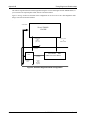
B.3.1
1PPS Alignment Modes
The receiver can operate in three different 1PPS alignment modes:
B.4
•
Constant Alignment: Implements an algorithm that keeps the 1PPS signal aligned on the UTC
second boundary.
•
1-Shot Alignment: This mode is used only when the receiver is using an externally controlled
oscillator. The receiver slews the 1PPS output to align it with UTC time once at power up.
Afterwards, the receiver assumes a perfect 10 MHz input reference frequency and output the 1PPS
signal accordingly. You can request the receiver to redo its one-shot alignment via command
Message ID #103. See Section B.7, Use of 1-Shot Alignment Mode on Page 41 for more
information on this mode.
•
Standard Alignment: This is the default mode for receivers without the Precise Timing
configuration block.
Receiver Self-Surveying
You can request the receiver to initiate a self-survey. In this case, the current position is averaged out and a
Figure-Of-Merit (FOM) reflecting the accuracy of the averaged position is computed. This process continues
until the desired surveying period has been reached. For more information on the FOM, please refer to the
ALLSTAR User’s Manual.
When the surveying process is completed, the associated data is then stored in Non-Volatile Memory (NVM).
The receiver then automatically switches to static mode using the last surveyed position, which becomes the
active known position.
SUPERSTAR Additional User Information Rev 0B
39
Appendix B
Timing Engine and Relationships
If you move the antenna, the self-survey process must be re-initiated.
B.5
TRAIM
The receiver implements a Time Receiver Autonomous Integrity Monitor (TRAIM) algorithm.
B.5.1
Alarm Limit and Time Integrity Limit
Two fundamental TRAIM concepts must be accurately defined in order to understand its use:
Alarm Limit (AL): The maximum error in the time estimate that the you accept to tolerate in your application.
You are advised if the time solution cannot be guaranteed to be accurate within this limit. You must provide this
value to the receiver.
Time Integrity Limit (TIL): The level of protection that the time estimator can offer. It defines the maximum
error that can be induced by one faulty measurement in the estimate without being detected. Beyond this limit,
TRAIM detects a fault in the time estimator. This value is computed in real-time based on parameters that
prevail at the time.
Therefore, when TIL > AL, an alarm is raised.
Determination of the Alarm Limit cannot be done without prior knowledge of the level of protection that can be
offered by the time estimator. The time estimator uses the pseudorange measurements to compute the clock
error. These measurements have different error sources: Selective Availability (S/A), ephemeris, ionospheric,
tropospheric and thermal noise errors.
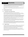
When a receiver is tracking the WAAS signal, it extracts ephemeris and ionospheric errors from the message.
The errors left in the measurements are residual errors left from tropospheric mismodeling and thermal noise.
Hence, you can logically estimate the TIL that can be expected with and without WAAS.
B.5.2
Status Indicators
In order to interpret correctly the status of the time solution, two separate status indicators must be taken into
account: the TRAIM solution status (TSS) and the Time Estimator status (TES). These are provided in Section
4.3.4, Precise Timing Information ID# 113 on Page 29.
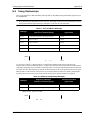
The Time Estimator status may take one of the values in Table 9:
Table 9: Time Estimator Status Conditions
Time Estimator Status (TES)
Condition
OK
All pseudorange residuals passed the detection test.
Fault Detected
A faulty residual has been detected but NOT isolated.
Fault Isolated
A faulty measurement has been detected AND successfully isolated.
Warning
Not enough satellites.
TRAIM provides either one of the status indicators in Table 10 to you at a given time:
40
SUPERSTAR Additional User Information Rev 0B
Timing Engine and Relationships
Appendix B
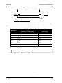
Table 10: TRAIM Solution Status Conditions
TRAIM Solution Status (TSS)
Condition
Successful
Time Estimator Status is set to OK and TIL < AL.
Warning
Time Estimator Status is set to WARNING or
[Time Estimator Status is set to FAULT DETECTED and TIL < AL]
Not Ready
Default value at power up.
Alarm
TIL > AL
Here are some examples of how you can interpret the current setting of both status indicators:
If TSS is set to ALARM and TES is set to OK, it indicates that there are not enough satellites to
guarantee the integrity of the clock solution.
If TSS is set to ALARM and TES is set to FAULT DETECTED, it indicates that there is a fault in
the measurement set that causes the TIL to be larger than expected. A bad receiver position
(programmed via Message ID# 80) may be the cause for such conditions.
If TSS is set to OK and TES is set to FAULT DETECTED, it indicates that a faulty satellite has
been detected but the TIL is still below the Alarm Limit. This may occur when there is a slow drift
building up in the measurements.
Furthermore, the 1PPS output can be programmed to be disabled when the alarm is raised, in order to enhance
timing integrity.
B.6
Receiver Reset Command
You can command the receiver to reset itself using a software command message (see Section 3.3.1, Reset
Receiver ID# 2 on Page 20). This causes the receiver to re-initialize its hardware and software, and reacquire
the satellites in view. Given the fact that many receivers are installed in remote locations and direct operation of
the receiver by maintenance staff is typically not possible, it is imperative that the host application closely
monitor the various status indicators, clock errors and residuals output in Message ID# 113 (see Page 29) and
reset the receiver if necessary.
B.7
Use of 1-Shot Alignment Mode
The purpose of this section is to present the use and behavior of the Timing Engine when it is in 1-Shot
Alignment Mode.
The current oscillator’s phase offset is represented by the clock bias. This value is constantly being computed
by the receiver and subsequently ‘consumed’ by realigning the system time based on this offset. You should not
incorporate the clock bias in the external oscillator steering algorithm. On the other hand, it is your
responsibility to nullify the clock drift in order to drive the 1PPS within 50 ns. The predicted time used to
output the 1PPS assumes a perfect 10 MHz frequency. This means that the 1PPS drifts according to the current
clock drift. The 1PPS residual represents the error between the time at which the 1PPS was output (that is, the
1PPS output time) and the time at which it should have been output. For example, if the receiver is
programmed to output the 1PPS aligned on the second edge, then the 1PPS residual is in fact the fraction of the
1PPS output time.
Once the external oscillator stabilizes at a perfect 10 MHz frequency, the 1PPS Residual remains constant; it
thus represents the actual phase offset. To remove this constant phase offset, you must send a Redo 1-Shot
Alignment command to the receiver. It removes this offset from the 1PPS; this is reflected in the reported 1PPS
Residual, which is a constant within ±50 ns. If you wish to generate a 1PPS aligned on a true zero error, a 1PPS
SUPERSTAR Additional User Information Rev 0B
41
Appendix B
Timing Engine and Relationships
can either be regenerated with external equipment using the receiver 1PPS signal and the 1PPS Residual, or
you can remove the reported phase offset from the external oscillator.
Figure 3 on Page 42 shows a schematic of the configuration to use for a receiver in 1-Shot Alignment mode
using a user-steered external oscillator.
.
10.0000 MHz
WAAS TIMING
ENGINE
RECEIVER
1PPS
OUTPUT
[ ± 50 nsec]
Frequency Drift
&
1PPS Residual
optional
VCXO
VCO
VOLTAGE
10.000000
MHz
SOFTWARE AFC
FIRST/SECOND ORDER
USER
1PPS
OUTPUT
(optional)
Figure 3: One-Shot Alignment Mode Configuration
42
SUPERSTAR Additional User Information Rev 0B
Timing Engine and Relationships
B.8
Appendix B
Timing Relationships
This section summarizes 1PPS with Binary, Message ID# 20, and NMEA timing relationships respectively for
the SUPERSTAR.
Be careful doing any substitution between receivers. Depending on the receiver type and software version,
message transmissions begin following a 1PPS pulse or just after the next 1PPS pulse.
Table 11: 1PPS and Binary Messages
Beginning of Messages
(reference to 1PPS rising edge)
Messagea
Transmission Duration
(approximate)
ID 23
15 ms (may be pushed by preceding message)
150 ms
ID 33
500 ms (always)
100 ms
ID 6,7
700 ms (always)
280 ms
ID 20
915 ms (always)
115 ms
ID 21
915 ms (may be pushed by preceding message)
130 ms
a.With software 169-614174-VAR
1PPS
33
23
6, 7
20 21
As you can see in Table 11, Message ID# 23 is output at the beginning of the GPS second (where the
measurements are taken) and Message ID# 21 is output at the end of the GPS second (when the solution is done
computing). Depending on the port baud rate, Message ID# 21 can end up being transmitted after the following
time mark. The time mark indicates the moment the measurements are taken. The predicted time used to tag the
Message ID# 23 is the GPS time at the time this set of measurements was taken. It is called a predicted time
because it has not been corrected for a clock bias that is only known when the solution is computed.
Table 12: 1PPS and Timing Binary Messages
Beginning of Messages
(reference to 1PPS rising edge)
Messagea
Transmission Duration
(approximate)
ID 20
350 ms
115 ms
ID 113
350 ms (may be pushed by preceding message)
100 ms
a.With software 169-614333-VAR
1PPS
20
113
SUPERSTAR Additional User Information Rev 0B
43
Appendix B
Timing Engine and Relationships
Table 13: 1PPS and Message ID# 20
a
1PPS
ID# 20
915 ms
a
a.With software 169-614174-B08
Message ID# 20 begins 915 ms after the 1PPS signal. The transmission duration is approximately 115 ms.
Table 14: 1PPS and NMEA Messages
Beginning of messages
(reference to 1PPS rising edge)
MESSAGEa
Transmission duration
(approximate)
GGA
815 ms
100 ms
GLL
915 ms
70 ms
GSA
400 ms
70 ms
GSV
300 ms
100 ms
VTG
720 ms
50 ms
ZDA
0 ms
60 ms
a.With software 169-614174-VAR
1PPS
ZDA
44
GSV GSA
VTG GGA
GLL
SUPERSTAR Additional User Information Rev 0B
Timing Engine and Relationships
SUPERSTAR Additional User Information Rev 0B
Appendix B
45
Appendix C
Measurements
This appendix explains in detail, for advanced users, the processing of the raw carrier and code phase
measurements of the SUPERSTAR. Basically, GPS receivers provide 2 types of raw measurements: raw code
phase measurements and raw carrier phase measurements. Before being used in an algorithm, the raw
measurements must be manipulated in order to provide a meaning to you, perhaps as a system integrator. Both
raw measurements are taken and latched simultaneously at the measurement TIC.
Raw measurements are provided in Message ID# 23. The structure of Message ID #23 is provided in Chapter 4
on Page 26. Details on the integrated carrier phase output by this message are given later in Section C.4 on
Page 49.
C.1
Measurements Concepts
C.1.1
Time Aligned and Not Aligned Concept
The aligned concept refers to the ability of the receiver to steer the measurement TIC.
Numerous clock steering schemes can be implemented. Some receivers directly steer the TCXO frequency.
Other receivers adjust the phase of the measurement TIC sporadically when the clock bias exceeds a threshold.
The phase of the sampler is modified at that time and the clock bias is adjusted accordingly.
In the SUPERSTAR, the clock steering is performed as described below. When the Time Aligned capability is
active, the receiver steers the measurement TIC of the receiver. The steering is performed in such a way that the
measurements are taken at the one second epoch (i.e. every second x.000000, x+1.00000 in the case of 1 Hz
measurements). To achieve that, the fractional seconds of the time tag, the clock bias and the clock drift are
used to steer the measurement TIC so that it occurs at the one second epoch. This way, receivers take their
measurements simultaneously. The steering occurs at each second.
For most applications, it is required to have the solution (and raw measurements) on the one-second epoch.
Therefore, the receiver should be set in Aligned Mode. For applications where it is not required to have the
solution on the one-second epoch, the receiver can be operated in Not Aligned Mode. You must know the
operating mode when you use the raw data in post processing.
Whether in Aligned Mode or Not Aligned Mode, the carrier phase and code phase measurements are taken at
the same time. The SUPERSTAR receiver operates by default in Aligned Mode. You can use binary command
ID# 103 (Set Date Time / Alignment Mode) to set the steering on or off. The selected mode is then activated at
the next power up and it is saved in Non Volatile Memory (NVM).
C.1.2
Doppler Concept
The GPS data is modulated by a 1.57542 GHz carrier, see Figure 4 and Figure 5 on Page 47. The effect of the
relative velocity of the satellite and the receiver (doppler effect) is to shift this signal in frequency. A carrier
tracking Phase Lock Loop (PLL) regenerates the carrier frequency shifted by the induced doppler. To
determine the doppler from the measurements, the nominal number of cycles has to be subtracted for the
measured number of cycles (which is composed of the nominal + doppler).
The carrier measurement that we output is the integrated carrier in 1024th of cycles from which the IF
frequency ramp is removed. What remains in the carrier phase measurement is therefore the satellite clock
drift, the doppler, an IF neglected fractional component and the part of IF corresponding to the correction to the
clock due to the clock drift.
46
SUPERSTAR Additional User Information Rev 0B
Measurements
Appendix C
Figure 4: Modulated GPS Data (Doppler Present)
0
1.5 GHz
Figure 5: Demodulated GPS Data (Doppler Present)
0
4 MHz
Because of the doppler shift, the reconstructed carrier is shifted in frequency. We reconstitute a frequency of
Fnom + Fdoppler
The carrier phase (Integrated Carrier Phase) that we generate is:
ICP = INTEGRATED MEASURED PHASE – INTEGRATED NOMINAL PHASE
The Integrated Carrier Phase (ICP) represents the Doppler shift frequency measured by the receiver and
integrated over time. To retrieve the instantaneous Doppler value from the ICP measurements, compute the
derivative of the ICP measurements. For example, the average Doppler value over a period of one second can
be computed by dividing the difference between two consecutive ICP measurement by the measurement
period:
(ICP(i)-ICP(i-1))/0.999999
for a measurement period of 0.999999.
If the time is not aligned, the ICP are accumulated for 1 s - 1 µs + Clock Drift. The nominal number of cycles is
computed for 1 s - 1 µs so if the TCXO does not drift, ICP = integrated cycles over 0.999999 s due to doppler.
If the TCXO drifts, the measurement period is affected by the clock drift and the measured ICP contains a
clock drift component in addition to the doppler.
If the time is aligned, the ICP are accumulated for 1 s. The nominal number of cycles is computed for 1 s - 1 µs
so if the TCXO does not drift, ICP = integrated cycles due to doppler + Nominal error. If the TCXO drifts, the
measurement period is not affected by the clock drift but the ICP contains the clock drift value.
C.1.3
Clock Drift Concept
A clock drift influences the duration of the measurements TIC by reaching the TIC count in advance or with a
delay depending on the drift direction. Time alignment compensates this effect by increasing or decreasing the
measurement period by delaying or advancing the occurrence of the TIC interrupt based on the predicted clock
drift.
Because the measurement TIC time base is the same as the carrier DCO clock, the clock drift has an impact on
the carrier cycles measurements. The number of cycles measured is directly affected by the clock drift. This
effect is fully compensated by changing the measurements period.
SUPERSTAR Additional User Information Rev 0B
47
Appendix C
Measurements
Table 15 on Page 48 summarizes the effect of the clock drift on the measurement period (time) and the code
and carrier phases.
Table 15: Clock Drift (CD) Effects
Measurement
C.2
Time Not Aligned
Time Aligned
Time
The measurement period varies in the
range [0.999999-Clock Drift,
0.999999+Clock Drift]
If CD = 0 then the period = 0.999999
If CD = +1 µs / 1s then the period = 1 s
The measurement period varies in the range
[1 s – 175 ns, 1 s + 175 ns]. This is due to the
time correction granularity of 175 ns.
The clock drift has little impact on the
measurement period since it influences only
the fraction of 175 ns offset from 1 s.
Code
CD effect present due to the measurement
period which is influenced by the clock
drift
CD has only a little effect.
Carrier
CD effect present due to the measurement
period which is influenced by the clock
drift.
The ICP output has the nominal cycles
removed for a period of 0.999999. The
ICP contains the clock drift.
The ICP needs to be corrected to account for
the measurement period which varies
between epochs. The ICP contains the clock
drift.
Code Phase Measurements
Raw Code phase measurements are punctual measurements. They can be used to derive pseudorange
measurements. Raw phase measurements are basically transmitted time (time of transmission in 1/1024 chip)
latched at the time TIC. The time tag (identification of the Measurement TIC) of that TIC is reported in
Message ID# 23. The pseudoranges are computed using the relation below:
ρi = [PredictedTimei − Floor (PredictedTimei )] − CodePhasei /(CodePhaseUnitPeriod )
if ρ i < 0
ρi + = 1
ρi = ρ i * C
Equation 1
Floor : Round towards minus infinity. The CodePhaseUnitPeriod is 1/1024 half chip.
CodePhaseUnitPeriod = 1023000*2048 where 1023000 = C/A code chip rate and 2048 is 2 * 1024.
C is the speed of light.
So to convert the code phase to time units, the code phase must be divided by the chip rate and multiplied by
the resolution.
The time of applicability of the measurements is the predicted time. This tag is said to be predicted since it
refers to a predicted time that is based on the previous estimate clock bias and clock drift. Therefore, the
predicted time is in error only by the second derivative of the clock bias. The SUPERSTAR steers the
measurement TIC continuously.
C.3
Carrier Phase Measurements
Raw carrier phase measurements (φ) are output as Integrated Carrier Phase (ICP). The 32 bits carrier phase
48
SUPERSTAR Additional User Information Rev 0B
Measurements
Appendix C
measurement is composed of the 30 bits ICP in 1/1024 cycles at the L1 frequency and a 2 bits status. When
read as an unsigned number, ICP wraps at value 2^30 (1/1024) cycles. This is done to reduce the bandwidth
requirements in Message ID# 23. To unwrap raw carrier phase measurements, we should use this process :
RAWICP = MSG23ICP / 1024
IF ( ABSOLUTE(DICP) > 2 19 )
IF ( (RAWICP I+1 - RAWICP I) > 0)
RAWICP I+1 AND ALL SUBSEQUENT RAWICP ARE DECREASED BY 2 20
ELSE
(EQ.-2)
RAWICP I+1 AND ALL SUBSEQUENT RAWICP ARE INCREASED BY 2 20
Equation 2
Unwrapped raw carrier phase are used to derive a quantity ICP (Integrated Carrier Phase). The ICP is
computed using the relation below:
ICPk (cycles) = RawICP0 + ∑ (∆ICPi + 4.5803)
k
i =1
∆ICP = ( RawICPi − RawICPi −1 )
Equation 3
When removing the nominal cycles, the measurement generator truncates the IF frequency to 1405400 Hz. A
correction of 4.5803 is applied on the RawICP to correct for this.
Correction to apply for the truncated IF:
TrunkCorrection = 1405400 − FIF * .999999 = 4.5804
where
FIF = 1405396.825 Hz
Equation 4
C.4
Carrier Phase In Message ID# 23
In Message ID# 23, the carrier phase measurement information bits are sent by the GPS receiver. The systems
use different detectors to set those 2 bits, which provide information about the whole cycle counter and cycle
fraction. See Table 16 below.
Table 16: Measurement Bits
Bit 0
Bit 1
Whole cycle bit (WC)
Fraction bit (FR)
The WC bit is used to qualify the status of whole cycle counter. Each time a channel is initialized the WC Bit is
set. Because of the nature of GPS navigation data message (bi-phase modulation), the receiver must adjust the
carrier phase measurement for a half-cycle count. When the software has detected the initial polarity of phase
tracking (0 or 180 degree boundary), the receiver adjusts the initial phase measurements. The Whole cycle
SUPERSTAR Additional User Information Rev 0B
49
Appendix C
Measurements
counter bit is clear. Then, the receiver starts the accumulation of the cycle and continues accumulation until
loss of power has been detected. The bit can be asserted when the receiver has detected parity error while
demodulating and assembling the GPS word. This status is latched over 1 second period.
The FR bit is used to qualify the status of the carrier phase measurement fraction. The receiver monitors the
stability of the phase tracking loop. A steady tracking is characterized by a very stable phase error in the phase
detector. When the phasor motion is determined to have exceeded a threshold in the one-second interval, the
FR bit of the measurement status is asserted.
In the SUPERSTAR, the WC and FR status bits are swapped as described in the ALLSTAR User’s Manual (e.g.
Status = 1, Phase unlock).
C.5
Coherence Between Pseudoranges and ICP
Unless you want to further smooth pseudoranges measurement with carrier phase, there is no need to obtain
coherent measurement. When you need a coherent set of ICP and pseudoranges (that is pseudoranges and ICP
exhibit the same slope), there is an additional manipulation that must be done either on the ICP or
pseudoranges. Coherency is very often verified by examining the first difference of ICP and first difference of
pseudorange measurements.
In both aligned and not aligned mode, the first difference of ICP and pseudorange differs for the
ionospheric differential that is causing advance on the carrier and a delay on the code measurement.
C.5.1
Time Adjustment Method
The first method is to modify the pseudoranges measurement to include the frequency drift in the pseudoranges
measurements. This allows you to match the ICP that contains the clock drift.
The equations that are used are only valid for sampling of one second. The slew value is only applicable for
the previous 1 second interval.
C.5.1.1
Adjusting the Measurement Period of the Pseudoranges
The sequence of predicted time that is obtained in Message ID# 23 is modified using the relationship below.
The process is initialized using PTime0 = GPSMessage23. PredictedTime. The Slew value is the number of 175
ns corrections that were applied on the measurement TIC to have a 1 second period.
PTimei +1 = PTimei + 1.00000 + ( SlewValuei +1 − 5.7142857) * 175e − 09
Equation 5
where 5.7142857 is the nominal Clock Drift expressed in 175 ns increments
For instance, if the clock drift is +1µs/1s, it compensates for the –1µs/1s nominal drift and no slew correction is
applied. The measurement time is 1 s – 1 µs to account for the clock drift even though the real measurement
time is 1 s.
The sequence of pseudorange measurements are computed:
50
SUPERSTAR Additional User Information Rev 0B
Measurements
Appendix C
ρi (m) = [PTimei − Floor ( PTimei )] − (CodePhasei / 2095104000)
if ρ i < 0
ρi + = 1
ρi = ρ i * C
where C is the speed of light
Equation 6
These equations reconstructs a sequence of pseudoranges that contains both the user/satellite doppler and
TCXO drift.
C.5.1.2
Adjusting the Measurement Period of the Carrier Phases
Because the integration period is not fixed, the carrier phase must be compensated for the effect of the
measurement period variation on the nominal cycles (which is 1/intermediate frequency). Therefore, the
nominal cycles at the IF frequency must be precisely adjusted to meet the measurement period. The
measurement generator assumes the measurement period to be 0.999999 s. Therefore two corrections must be
applied on the output ICP. The first correction is to account for the truncated IF. The seconds correction is to
account for a measurement period different than 0.999999 s. The Slew value is the number of 175 ns
corrections that were applied on the measurements TIC to have a 1 s period.
Correction to apply for the measurement period different than 0.999999 s
DriftCorrection = FIF *175ns * Slew = 0.245944444375 * Slew
where
FIF = 1405396.825 Hz
Equation 7
With the two corrections applied, the reconstruction of the ICP becomes:
ICPk = RawICP0 + ∑ (∆ICPi + 4.5803 − 0.245944444375 * SlewValuei )
k
i =1
∆ICP = ( RawICPi − RawICPi −1 )
Equation 8
The slew value is contained in Message ID# 23. By using these equations and by calculating the first difference
of pseudoranges measurement and delta-ranges measured on the carrier, a match between ICP and
pseudoranges is obtained.
C.5.2
Double Difference Technique
When using the carrier phase measurement with a double difference technique non-coherency constant is the
same for all satellites and therefore drop out of the equation. You can use Equation 2 on Page 49 to unwrap the
ICP measurement.
SUPERSTAR Additional User Information Rev 0B
51
Appendix C
C.5.3
Measurements
Matching the Carrier Phases and the Code Phases for 1 Second
To account for the true measurement period, the measurements have to be adjusted for the true measurement
period. In align mode, the measurement period is 1 s.
The sequence of predicted time is taken directly from Message ID# 23 without adjustments. With this time, the
sequence of pseudorange measurements are computed to produce pseudorange measurements for the actual
measurement period which is slightly different than 1 s.
ρi = [PredictedTimei − Floor (PredictedTimei )] − CodePhasei /(CodePhaseUnitPeriod )
if ρ i < 0
ρi + = 1
ρi = ρ i * C
Equation 9
The Carrier phase measurements must be modified to match the 1 s code phase measurements. The following
equations does the job.
k
ICPk (cycles) = RawICP0 + ∑ (∆ICPi + TrunkCorrection − TimeCorrectioni − ClockDrifti * c / Lambda ))
i =1
where
∆ICP = ( RawICPi − RawICPi −1 )
TimeCorrectioni = Slewi * f IF *175e − 9
f IF = 1405396.825Hz
ClockDrifti = 175e − 9 * Slewi − NominalDrift − (PredictedTimei − PredictedTimei −1 − 1.0)
NominalDrift = 1e − 6
Equation 10
The TimeCorrection element adjusts the ICP to the effective measurement period. It is used to remove the
nominal cycles for the period going from 0.999999 to the actual measurement period. The clock drift is
removed from the ICP because the clock drift is absent on the pseudorange.
This method for carrier and code phase matching works for time measurements only. It is also applicable for 1
Hz measurements only since the slew is required. The slew is output only once a second.
Note that the slew is used to remove the clock drift element. The clock drift can be computed externally and
then removed. Doing that would allow you to work with any rate of measurements, both aligned or not aligned.
52
SUPERSTAR Additional User Information Rev 0B
Appendix D
Waypoint Navigation
The purpose of this appendix is to familiarize you with the SUPERSTAR Waypoint Navigation feature.
Waypoint Navigation is a factory-installed option (also known as a config block) on your GPS receiver. Verify
that you have configuration part number 169-613955-009 installed within the SUPERSTAR.
The Waypoint Navigation feature requires the use of the NMEA protocol. An explanation of the supported
NMEA protocol and field definitions is provided in the ALLSTAR User’s Manual to assist you in understanding
the Waypoint Navigation option.
For further details on the NMEA message structure and formats, please refer to NMEA 0183 specification
(available from NMEA executive office Tel. 252-638-2626; Fax. 252-638-4885; internet: www.nmea.org).
D.1
Start-up in NMEA Protocol Mode
To setup the I/O operating mode to NMEA protocol:
Apply ground to the DISC_IP_3 signal (connector J1, pin 7) of the SUPERSTAR.
D.2
Waypoints
The SUPERSTAR can perform simple navigation calculations via the serial communications port.
A database containing a maximum of 100 waypoints can be maintained within the receiver. Waypoint entry,
retrieval and editing is accomplished via defined input/output messages. Waypoint positions are in the Military
Grid Reference System (MGRS) and Universal Transversal Mercator (UTM) co-ordinate system formats. A
waypoint is defined by an identifier number and an 8 character name.
D.3
Navigation Procedure
1. Route Planning
Set up a navigation plan by defining a number of waypoints on your route. Load the plan into the
SUPERSTAR by sending a series of "Define Waypoint" messages (NMEA ID# 009). Each ID#
009 NMEA message defines the exact location of a waypoint in MGRS format.
2. Navigation Solution
Request a navigation solution by sending a "Select Active Waypoint" message (NMEA ID# 010).
The SUPERSTAR replies, typically within 3 seconds, with a navigation solution from the local
position to that waypoint using the currently selected datum. This message (NMEA ID# 906)
contains bearing (in degrees true north), range (in meters), and delta elevation (in meters)
information.
3. Current Status
The SUPERSTAR transmits navigation status and the current user position in both UTM and
MGRS formats. These messages are defined by NMEA message ID#s 900, 905 and 907
respectively.
53
SUPERSTAR Additional User Information Rev 0B
Appendix D
54
Waypoint Navigation
SUPERSTAR Additional User Information Rev 0B
Appendix E
Satellite-Based Augmentation System
A Satellite-Based Augmentation System (SBAS) is a type of geo-stationary satellite system (for example
WAAS and EGNOS) that improves the accuracy, integrity, and availability of the basic GPS signals. Accuracy
is enhanced through the use of wide area corrections for GPS satellite orbits and ionospheric errors. Integrity is
enhanced by the SBAS network quickly detecting satellite signal errors and sending alerts to receivers to not
use the failed satellite. Availability is improved by providing an additional ranging signal to each SBAS
geostationary satellite.
SBAS includes the Wide-Area Augmentation System (WAAS), the European Geo-Stationary Navigation
System (EGNOS), and the MTSAT Satellite-Based Augmentation System (MSAS). At the time of publication,
there are two WAAS satellites over the western Atlantic Ocean and the Pacific (PRN 122 and PRN 134
respectively) and one EGNOS satellite over the eastern Atlantic Ocean (PRN 120). SBAS data is available
from any of these satellites and more satellites will be available in the future.
The card is only able to receive corrections from an SBAS satellite if it has the SBAS option installed. It may
also have the the SUPERSTAR Timing Engine option installed. They are independent from one another, but
together yield a more accurate 1PPS alignment and enhanced timing integrity. See also Appendix B, Timing
Engine and Relationships, starting on page 38.
In StarView, the terms WAAS and GIC are used to include all SBAS satellites.
The primary functions of SBAS include:
•
•
•
•
•
•
•
•
data collection
determining ionospheric corrections
determining satellite orbits
determining satellite clock corrections
determining satellite integrity
independent data verification
SBAS message broadcast and ranging
system operations & maintenance
As shown in Figure 6, The SBAS Concept on Page 56, the SBAS is made up of a series of Reference Stations,
Master Stations, Ground Uplink Stations and Geostationary Satellites (GEOs). The Reference Stations, which
are geographically distributed, pick up GPS satellite data and route it to the Master Stations where wide area
corrections are generated. These corrections are sent to the Ground Uplink Stations which up-link them to the
GEOs for re-transmission on the GPS L1 frequency. These GEOs transmit signals which carry accuracy and
integrity messages, and which also provide additional ranging signals for added availability, continuity and
accuracy. These GEO signals are available over a wide area and can be received and processed by the SMART
Antenna with appropriate firmware. GPS user receivers are thus able to receive SBAS data in-band and use not
only differential corrections, but also integrity, residual errors and ionospheric information for each monitored
satellite.
The signal broadcast via the SBAS GEOs to the SBAS users is designed to minimize modifications to standard
GPS receivers. As such, the GPS L1 frequency (1575.42 MHz) is used, together with GPS-type modulation e.g. a Coarse/Acquisition (C/A) pseudorandom (PRN) code. In addition, the code phase timing is maintained
close to GPS time to provide a ranging capability.
55
SUPERSTAR Additional User Information Rev 0B
Appendix E
Satellite-Based Augmentation System
Geostationary
Satellite (GEO)
L1
GPS Satellite
Constellation
L1 & L2
L1 & C-band
Integrity data,
differential corrections,
and ranging control
GPS User
C-band
Reference Station
Reference Station
Master Station
Reference Station
Ground Uplink
Station
Integrity data,
differential corrections,
time control, and status
Figure 6: The SBAS Concept
E.1
SBAS Receiver
Many models of the NovAtel receivers are equipped with an SBAS (for example WAAS and EGNOS) option.
The ability to simultaneously track two SBAS satellites, and incorporate the SBAS corrections into the position,
is available in many models.
These models can output the SBAS data in log format (Message ID#s 67 and 68), and can incorporate these
corrections to generate differential-quality position solutions. Standard SBAS data messages are analyzed based
on RTCA standard DO-229B Change 1 Minimum Operational Performance Standards for GPS/WAAS airborne
equipment.
A SBAS-capable receiver will permit anyone within the area of coverage to take advantage of its benefits.
E.2
SBAS Messages
Two SBAS-specific messages are available if you have a SBAS-capable model. Details of Message ID#s 67
and 68 can be found in Chapter 4, Output Messages starting on Page 28. You will find more on message
structure and other message descriptions in the ALLSTAR User’s Manual.
E.2.1
Logging Message ID# 67
To get the raw SBAS data out of the receiver, you must explicitly request Message ID# 67 through StarView as
follows:
1. Select Xmit Msg | General Message Request from the main menu
2. Enter 67 (Raw SBAS Message) and select Continuous in the Request I/O Message dialog box
3. Select Window | Messages | Received Messages from the main menu. Watch the Message ID# 67
count incrementing.
56
SUPERSTAR Additional User Information Rev 0B
Satellite-Based Augmentation System
Appendix E
4. Select one of the Log Incoming Data icons, shown below, to log all incoming messages:
The application will request a filename where you want to store data. The filename is then echoed
in the bottom of the main StarView Window.
5. Click on the icon again to stop the logging of data.
The program cget67.exe is a 32-bit console application that extracts Message ID# 67 and formats it into an
ASCII format as follows:
480790.00 3 530D1FFDFFDFFFF79FFDFFFF75FFDFFC09BCF5FFDFFFBB8FB87B84FB83BE2B80
480791.00
63 9AFC00000000000000000000000000000000000000000000000000001C877740
480792.00
24 C663F69FFDFFC0000000013B8000A09B12000000000000001FE00BEB03BB7980
480793.00
62 53FAAAAAAAAAAAAAAAAAAAAAAAAAAAAAAAAAAAAAAAAAAAAAAAAAAAAA8EC0ED00
480794.00
0 9A021FFC1ABFCDFFDFFDFFF8F9FFDFFC01C1D5FFFFFB8FBBB93B94F9268619C0
480795.00
25 C6668B000000000000000000002F808000000000000000000000000028925E40
480796.00
3 530E1FFDFFDFFFFA9FFDFFFF05FFDFFC08FD11FFDFFFBB8FB87B84FB864AC580
480797.00
63 9AFC00000000000000000000000000000000000000000000000000001C877740
480798.00
24 C663F19FFDFFC0000000013B800080800000000000000000000000002BDEB
where, for example:
480790.00 is the GPS Time
3 is the SBAS Message Type
and the rest is the 250-bit SBAS message packed into a 32-byte frame and the 6 MSB are set to zero
E.3
SV Deselection
StarView allows you to deselect GPS and SBAS system satellites. Select Tool Settings | Deselect | SVs from the
main menu and the SV Deselection dialog will appear as seen in Figure 7 below.
Figure 7: SV Deselection
To track one SBAS satellite in particular, do the following:
SUPERSTAR Additional User Information Rev 0B
57
Appendix E
Satellite-Based Augmentation System
1. Select WAAS SVs
2. Select the SBAS satellite that you wish to track by deselecting all the others. This insures that the
receiver will search for a satellites that is known to be operating and thus ensure quick acquisition/
reacquisition of the active SBAS satellite.
By default, if you select WAAS SVs alone, the unit is only searching for satellite PRNs 120, 122 and 134.
E.4
StarView SBAS Message Status
Figure 8: SBAS Status
The WAAS Status window, see Figure 8, shows you the number of valid SBAS messages that are being
decoded for a specific SV number since the last power-up. When the Valid Messages count is not incrementing,
it means that either the receiver is not tracking any SBAS satellites, or it is unable to demodulate the SBAS bit
stream.
E.5
SBAS Satellite ID
Table 17: SBAS Satellite Identification
SV#
Description
120
AOR-E: Atlantic Ocean Region (E15)
121
Not allocated
122
AOR-W: Atlantic Ocean Region (W55)
134
POR: Pacific Ocean Region (E178)
Figure 9 on Page 59 shows the coverage of two WAAS satellites (PRN 134 - yellow and PRN 122 - red):
58
SUPERSTAR Additional User Information Rev 0B
Satellite-Based Augmentation System
Appendix E
San Diego
Figure 9: WAAS Coverage
SUPERSTAR Additional User Information Rev 0B
59
Appendix F
Updating Receiver Firmware
This appendix will explain how to update the receiver's firmware from a binary file using the programming
utility.
F.1
Introduction
GPS receivers have their firmware stored in flash memory and therefore you can update its content in the field.
This feature increases tremendously the receiver's flexibility allowing you to always use the latest version of
the firmware, thus, continuously improving the receiver's capability.
F.2
Description
For the purpose of the explanation, we will consider that the firmware name is filename and that the
programming utility name is prog.
The programming utility is a DOS based command line utility which, once invoked with the proper parameters,
will update the receiver's firmware. Although it is DOS based, it can be used on computer using Windows 95
and higher or Windows NT operating system.
Usually, the programming utility and the firmware binary file will be provided to the customer in zip files.
Therefore, those files must be unzipped before proceeding with the firmware update.
If you invoke prog without any parameters or with a missing parameter, a pop-up menu will appear.
The programming utility requires four parameters to perform the update task. The first one must be the
firmware binary filename. The second is the port of the PC used to communicate with the receiver. The third
one is the communication protocol used (binary or NMEA). Finally for the fourth and fifth parameters, you
need to supply the synchronization speed (the actual speed of the GPS receiver) and the programming speed
(communication speed used while programming the board).
PROG FILENAME PORT PROTOCOL SYNC PROGRAMMING
Table 18: Updating Parameters
Parameter
F.2.1
Possible Value
filename
any valid filename in the 8.3 DOS standard
port
Any number representing a valid port number installed on the
PC. e.g. 1 for COM1, 3 for COM3,…
protocol
Used to indicate the current protocol used by the GPS receiver.
0: Binary protocol
1: NMEA protocol
sync
Current speed used by the GPS receiver.
Any standard speed between 300 and 115200.
programming
Speed used to transmit information to the GPS receiver.
Any standard speed between 300 and 115200.
Example
The following command line would used prog.exe to update the GPS receiver's firmware, using the binary file
called 614174.007. The receiver is in binary mode at 9600 bps and we want to transmit the data at 115600 bps.
COM4 of the PC is used. Therefore you would enter the following line:
SUPERSTAR Additional User Information Rev 0B
60
Updating Receiver Firmware
Appendix F
PROG 614174.007 4 0 9600 115200
F.3
Troubleshooting
F.3.1
Firmware Partially Erased or Invalid
If, upon powering up the receiver, the following message is displayed at 9600 bps:
BAD OPERATIONAL JUMPING IN PROGRAMMING MODE
then, you have to use the same command again with the synchronization speed set to 9600 bps for the
SUPERSTAR or SUPERSTAR II receivers and to 19200 for the ALLSTAR receiver. The remaining
parameters are according to your setup.
Please refer to the ALLSTAR manual (Appendix F) for details on how to hard program the receiver.
SUPERSTAR Additional User Information Rev 0B
61
Index
(TCXO), Temperature Compensated
Crystal Oscillator, 46
1PPS, 30, 37–39, 41–44
1-shot alignment, 15, 41–42
A
active antenna, 15–16
alarm, 40–41
limit (AL), 40
aligned mode, 52
alignment
1-shot, 41–42
mode, 18
almanac, 16
antenna, 9, 14–15, 34, 37, 39–40
active, 15–16
B
baud, 18
bearing, 53
C
cable
null modem, 14
RF, 14
warranty, 9
carrier phase, 27, 48
CD, 14
clock, 37, 46
bias, 30, 38, 41
drift, 38, 41, 47, 52
code phase, 26, 48
communication, 14, 34
configuration, 18
connectors, 15–16, 37
continuous, 15
Customer Service, 10
cycle slip, 27
D
datum, 31
default configuration, 18
delay, 30
development kit, 35
device, supercap, 16
DGPS, 15, 18
SUPERSTAR Additional User Information Rev 0B
dimensions, 33, 35
discharge (ESD), electrostatic, 14
discretes, 17, 36–37
doppler, 46
double difference technique, 51
dynamics, 34, 38
E
electrostatic discharge (ESD), 14
elevation, 53
enclosure, 14
engine, timing, 38, 55
errors, 40
F
field types, 19
figure-of-merit (FOM), 12, 39
file, save to, 15
firmware update, 10, 60
frequency, 33
G
GEO, SBAS, 55
grid, 31
H
harness, wiring, 14
hexadecimal, 19
humidity, 35
I
I/O characteristics, 36
ID# 103, Set Time, 24
ID# 113, Precise Timing Information,
29, 41
ID# 2, Reset Receiver, 20, 41
ID# 20, Navigation Data (User), 18, 38,
43–44
ID# 21, Navigation Data (GPS), 43
ID# 23, Measurement Block, 26, 29, 43
ID# 67, SBAS Current Message, 28, 57
ID# 68, SBAS Message Status, 28
ID# 69, Set Timing Parameters, 21, 29
ID# 80, Set Operating Mode, 22, 39, 41
ID# 90, Satellite Deselection, 23
ID# 905, User Position in UTM, 31, 53
ID#23, Measurement Block, 49
62
Index
P
PC, 14
performance, 34
phase
carrier, 27, 48
code, 26, 48
pins, 36–37
planning, route, 53
port
auxiliary, 15
main, 15
serial, 14, 37
position, 14, 16
power, 16, 37
specifications, 34
supply, 14
protocol, 18–19, 25, 37
pseudorange, 40
pseudoranges measurement, 50
pulse width, 39
input
discrete, 17
pins, 36
voltage, 34, 36
integrity, 41
interface, 16, 37
K
kit, development, 35
L
limits, 40
M
measurements, 46
carrier phase, 48
code phase, 48
period, 52
pseudoranges, 50
TIC, 46
memory, 16, 18
messages, 15
default, 18
input, 34
output, 23, 34
Military Grid Reference
(MGRS), 53
mode
aligned, 52
modem cable, null, 14
Q
quick start, 13
System
N
navigation
solution, 53
status, 53
waypoint, 24, 31, 53
NMEA, 17, 24, 31, 44, 53
non-volatile memory (NVM), 18, 37
null modem cable, 14
number, SV, 26
O
one shot, 15
operation
static, 30, 38–39
timing mode, 30
oscillator, 41–42
SUPERSTAR Additional User Information Rev 0B
R
range, 53
reset, 37, 41
residual, 30, 38, 40, 42
RF
cable, 14
connector, 16
route planning, 53
S
satellite, 40
save to file, 15
SBAS, 25, 28, 55–56, 58
scope, 11
self-surveying, 22, 38–40
serial
communication, 34
port, 14, 37
setup, 13
signals, 36
signal-to-noise ratio (SNR), 26
slip, cycle, 27
software, StarView, 14
start
63
Index
quick, 13
warm, 16
StarView software, 14
static operation, 30, 38–39
status indicators, 40–41
supercap device, 16
SV number, 26
synchronization, 38
T
temperature, 35
Temperature Compensated Crystal
Oscillator (TCXO), 46
time, 16, 26, 31, 41
configuration, 42
engine, 38, 55
estimate, 40
integrity limit (TIL), 40
operating mode, 30
receiver autonomous integrity
monitor (TRAIM), 30, 40
relationships, 38, 43
to first fix (TTFF), 34
transmission, 44
types, 19
U
Universal Time Coordinated (UTC), 18,
21, 24, 29–31, 38–39
Universal
Transversal
Mercator
(UTM), 31, 53
update firmware, 10, 60
V
valid almanac, 16
voltage, 36
W
WAAS, 25, 28, 30, 38, 42, 58
warm start, 16
warranty, 9
waypoint navigation, 24, 31, 53
weight, 35
wiring harness, 14
Z
zone, 31
64
SUPERSTAR Additional User Information Rev 0B
Index
SUPERSTAR Additional User Information Rev 0B
65
Recyclable
Printed in Canada on recycled paper
OM-20000079
Rev 0B
2003/07/07