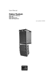
1
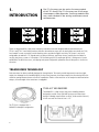
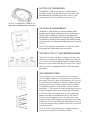
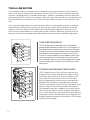
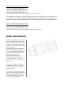
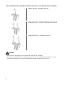
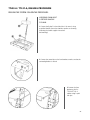
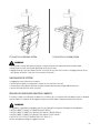
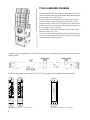
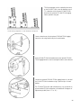
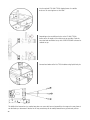
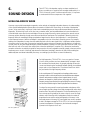
OWNER MANUAL
TTL31-A
TTL33-A
TTL55-A
LINE ARRAY MODULES
Rev E
2
CONTENTS
1.
INTRODUCTION
TRANSDUCERS TECHNOLOGY
ELECTRONICS
CABINET AND MECHANICS
2.
SAFETY PRECAUTIONS
GENERAL OPERATING PRECAUTIONS
3.
VOLTAGE
CURRENT
GROUNDING
AC CABLES DAISY CHAINS
POWERING FROM THREE PHASE
4.
AUDIO CONNECTIONS AND CABLING
SIGNAL CABLE DAISY CHAINS
INPUT PANEL LEDS
5.
GENERAL RIGGING WARNINGS AND SAFETY PRECAUTIONS
“RCF SHAPE DESIGNER” SOFTWARE AND SAFETY FACTOR
RIGGING SYSTEM
FLY-BAR SYSTEM
RIGGING PROCEDURE
TTL33-A GROUND STACKING
RCF TTL33-A KART
6.
HOW LINE ARRAYS WORK
DISTANCE TO THE FAR FIELD OF A LINE ARRAY
SYSTEM CONFIGURATION
ARRAY SYSTEM DESIGN
RCF SHAPE DESIGNER SOFTWARE
CLIMATIC EFFECTS
AMPLIFIER GAIN SETTINGS
USING SUBWOOFERS
7.
PARTS INSPECTION CHECK LIST
GENERAL SAFETY
INSTRUCTION AND WARNINGS
POWER REQUIREMENTS AND SET-UP
THE TTL SYSTEM
RIGGING THE SYSTEM
SOUND DESIGN
MAINTENANCE PROCEDURES
8.
TECHNICAL SPECIFICATIONS
3
1.
INTRODUCTION
The TT+ line arrays are the active line array module
of RCF TT+ family. The TT+ line arrays are a full range,
ultracompact, wide dispersion, line array modules that
sets a new standard in the touring and theatre sound
reinforcement.
Thanks to digital amplifiers, high power neodymium transducers and well designed cabinet and mechanics the
TTL33-A and TTL31-A are unique products and offers the maximum output per size and weight; acoustically are “fully
horn loaded” in order to properly control directivity and to provide the highest sensitivity. The system is very easily
configurable; the cabinet is 15° shaped and is possible to build very small flown clusters starting from 4 modules or
very big, long throw, systems of 16 modules. A 32 bit floating point DSP, sampling at 96 kHz, is taking care of system
equalization, 24 db/oct crossovers, soft clipping and system configuration parameters like air absorption or cluster size
correction.
TRANSDUCERS TECHNOLOGY
Each transducer has been specifically designed for the application. The woofer provide large excursion and very light
weight, the midrange has an incredibly high BL for best vocal presence, the unique compression driver design offers the
minimum spacing between throats to avoid HF cancellation. Thanks to the extensive use of neodymium and new basket
designs, the total weight of the transducers is negligible!
TTL33-A 8” NEO WOOFERS
The MB8N251 is a high output, high power handling mid-bass
designed to provide a very tight and fast response in band-pass
designs. Extended response down to 60 Hz, inside-outside voice coil,
M-roll surround. The voice coil size is 2.5”.
The TTL33-A is equipped with 2
MB8N251in bandpass configuration:
4
THE TTL31-A 8” NEO WOOFERS
The MB8N252 is a high output, high power handling mid-bass
designed to provide a very tight and fast response in hybrid reflexhornloading designs. Extended response down to 60 Hz, insideoutside voice coil, M-roll surround. The voice coil size is 2.5”.
The TTL31-A is equipped with 1 MB8N252 in a
hybrid reflex-hornloaded bandpass configuration:
THE TTL33-A 8” NEO MIDRANGE
The MR8N251 is a high efficiency, low distortion midrange specially
designed to provide superior sound pressure level in a very compact size.
The total weight is reduced to less than half of a comparable ceramic
midrange thanks to an incredibly powerful neodymium magnet assembly.
Every detail of this speaker has been optimised to offer maximum linearity
and perfect control to the midrange and midhigh frequencies. The voice coil
size is 2.5”.
In the TTL33-A application, the MR8N251 is frontally horn loaded
and equipped with a lightweight aluminum back-can.
THE TTL33-A/ TTL31-A 1” NEO COMPRESSION DRIVER
The ND1411-MT compression driver is a design conceived for array
applications: very high output, high power handling, the overall size
is very small for the minimum spacing. Neodymium magnet, titanium
dome, mylar surround, radial phase plug. The voice coil size is 36 mm.
The TTL33-A /TTL31-A is equipped with 3 ND1411-MT in horn-loaded
configuration.
HIGH FREQUENCY HORN
The high frequency horn is one of the key parts of the line array.
One of the biggest problems in line array designs is the difference in
path lengths from driver to driver in high frequencies; this is cause of
hf comb filtering and cancellation. To avoid this problem many array
designs present in front of the driver complex “acoustic chambers”
to equalise different paths ( sound chambers, reflective chambers,
waweguides,…). Those devices are usually creating impulse response
problems and acoustic loads that are changing with the frequency.
In the TTL33-A/TTL31-A horn design, thanks to the very small overall
diameter of the drivers, the spacing between ND1411-MT centres of
emission in the array application is only 70 mm. Thanks to this small
spacing it has been possible to equalise the different paths with a simple
straight horn, with a very simple design that avoids reflections. The result
is a very even frequency response, a coherent wave source, a very natural
and transparent sound.
The TTL33-A/TTL31-A high frequency horn is designed to create a
continuous and coherent line from cabinet to cabinet.
5
TTL55-A LOW SECTION
At low frequency vertical line array pattern control is reached by the constructive interference of the low frequency
sources on line array axis and destructive interference on line array off axis. This is true over a frequency range where
sources are omni-directional (for a 12inch below 400Hz) and its separation is comparable or lower than signal wave
length reproduced (TTL55-A vertical 12inch separation is 380mm this means that we should control vertical pattern with
constructive and destructive interference up to 1100Hz). Both these conditions are satisfies in the range where 12inch
works.
As the sound wave length decreases, more and more drivers, smaller in size and spaced more closely, are required to
maintain directivity. Practical line array systems act as line arrays only in the low and mid frequencies. For the high
frequencies, some other method must be founded to reach vertical directional characteristics that match those of
the low. The most practical method is to use wave guides coupled to the drivers. Rather than using constructive and
destructive interference, the waveguides achieve directionality by confining sound into a specified coverage pattern.
TTL55-A MID FREQUENCIES
TTL55-A mid frequencies are reproduced by one 10 inch dedicated
midrange coupled to dedicated unique 90°H by 15°V wave guide. It has
been designed with exponential expansion area for best low frequencies
coupling and to minimize distortion and back reflections. Wave guide has
been designed to coupled a single annular isophase wave front on 10
inch cone to a unique rectangular horn throat capable to create a single
isophase rectangular output. This wave guide is than coupled to other
horns wave guide to refine the narrow vertical coverage pattern and wide
horizontal coverage pattern. Final result show extremely narrow vertical
pattern control.
TTL55 MID-HIGH FREQUENCY WAVE GUIDES
TTL55 is loaded with three 2.5inch voice coil compression driver
designed with the minimum overall dimension actually on the pro
audio market 4inch (102mm!!). By the driver compact size it has
been possible to fit three of them in only 310mm with evident
benefit on tight directional vertical control over the frequencies. A
dedicated TTL55 high frequency wave guide couples three driver
circular (1.3inch diameter) isophase exit to the six rectangular output
apertures through six channels with exponential area expansions.
Each rectangular channel exit is capable to form a perfect isophase
wave front over the frequencies for best coupling to other adjacent
exits. From here another horns wave guide with constant directivity is
introduced for wide 90° horizontal pattern control. Finally, both mid
and high frequency wave guides are closely fitted on TTL55 for better
coupling on horizontal plane.
6
ELECTRONICS
All the TT+ line arrays electronic is in a strong, separate, extruded
aluminum housing. From the right side of the amplification module
are available Neutrik Powercon input and output, on/off switch
and protected ports for the ventilation fan. From the left side of the
amplification module are available all the inputs and controls. The
amplification module is connected to the main cabinet in 4 points
with M6 metric screws and easily removable.
INPUTS
The TT+ line arrays input section offers XLR input, XLR output for daisy chaining, and sensitivity control (+∞, -2 dB).
A set of 5 switch is used for parameters and configuration control: air absorption, cluster size, low frequencies cut off.
A data port is available for firmware upgrade and special applications.
SIGNAL PROCESSING
Each TT+ line arrays cabinet features a last generation, 32 bit floating point DSP for audio processing and a separate
micro-processor for general system management.
Analog-digital conversions are operated from high resolution 24 bit, 96 kHz converters.
The signal processing make use of state-of-the-art algorithms and performs a very accurate system equalization (6 point
each band), 24 dB/oct crossovers, transducers time alignment, hard limiter circuit, soft clipping circuit.
The DSP reads the system configuration and adjust the parameters to optimise the performances related to air absorption, cluster
size and subwoofer filtering. “RCF Shape Designer” software helps defining all parameters for specific projects and system designs.
AMPLIFIERS
The TT+ line arrays amplification power is delivered from high accuracy, high power digital amplifiers. Very low distortion
and very natural sound combined to minimum weight and minimum heat dissipation are the distinctive characteristics of
this unique amplifier’s design.
THE TTL55-A AMPLIFICATION SECTION FEATURES:
• 2x1500 watt switching power supply module
• 2x1000 watt low frequency digital amplifier module
• 1000 watt midrange digital amplifier module
• 500 watt high frequency digital amplifier module
• extra capacitor bus able to sustain the full voltage for over 100 ms burst signals
The total available power supply power is 3000 watts and can be distributed to the 4 final amplifier sections. Each
amplifier section has a very high maximum output power capability in order to provide, when necessary, maximum
output bursts in a specific frequency range. A small fan, speed controlled, guarantee the air circulation inside the
amplifier in the most demanding situations.
7
THE TTL33-A AMPLIFICATION SECTION FEATURES:
• 750 watt switching power supply module
• 500 watt low frequency digital amplifier module
• 500 watt midrange digital amplifier module
• 250 watt high frequency digital amplifier module
• extra capacitor bus able to sustain the full voltage for over 100 ms burst signals
The total available power supply power is 750 watts and can be distributed to the 3 final amplifier sections. Each amplifier section
has a very high maximum output power capability in order to provide, when necessary, maximum output bursts in a specific
frequency range. A small fan, speed controlled, guarantee the air circulation inside the amplifier in the most demanding situations.
THE TTL31-A AMPLIFICATION SECTION FEATURES:
• 750 watt switching power supply module
• 500 watt low frequency digital amplifier module
• 250 watt high frequency digital amplifier module
• extra capacitor bus able to sustain the full voltage for over 100 ms burst signals
CABINET AND MECHANICS
The TT+ line arrays cabinet is in baltic birch
plywood, coated with high resistance epoxy
paint. The wood quality, the small thickness
in conjunction to a proper internal bracing,
the metal structure design make this cabinet
very light and robust.
The mechanical suspension and orientation
system is in high quality steel, very precise and
easy to use. All the mechanical parts are laser
cut, machined and precision assembled with
metric screws and threat locker.
The design guarantees a precise
inclination of each module from 0° up
to 15° in small 2° steps for TTL33-A /
TTL31-A and from 0° to 7° in steps of 1°
for TTL55-A.
The system is very light and can be moved
or transported from one or two people
using the side handles or rear handles (on
the amplifier sides).
The suspension system is designed to have a
proper safety factor (configuration dependent).
Using the “RCFShape Designer” software it
is very easy to understand safety factors and
limits for each specific configuration.
8
2.
GENERAL
SAFETY
INSTRUCTION
AND WARNINGS
IMPORTANT NOTE
Before connecting using or rigging the system, please
read this instruction manual carefully and keep it
on hand for future reference. The manual is to be
considered an integral part of the product and must
accompany the system when it changes ownership as
a reference for correct installation and use as well as
for the safety precautions. RCF S.p.A. will not assume
any responsibility for the incorrect installation and/or
use of the product.
WARNING
• To prevent the risk of fire or electric shock, never
expose this equipment to rain.
• The system TT+ line arrays should be rigged and
flown by professional riggers or trained personnel
under professional riggers’ supervision.
• Before rigging the system carefully read this manual.
SAFETY PRECAUTIONS
1. All the precautions, in particular the safety ones, must be read with special attention, as they provide important information.
2. The power supply voltage of this equipment is sufficiently high to involve a risk of electrocution; therefore, never
install or connect the product with the power supply switched on.
3. Before powering up the amplifier, make sure that all the connections have been made correctly and that the voltage
of your power mains corresponds to the voltage shown on the rating plate on the unit; if it does not, please contact
your RCF dealer.
4. The metallic parts of the unit are earthed by means of the power cable. In the event that the current outlet used
for power does not provide the earth connection, contact a qualified electrician to earth the equipment using the
dedicated terminal.
5. To protect the power cable from damage, make sure that it is positioned so that it cannot be stepped on or crushed
by objects.
6. To prevent the risk of electric shock, never open the amplifier. There are no parts on the inside that the user needs to
access.
7. Make sure that no objects or liquids can get into the amplifier, as this may cause a short circuit.
8. Never attempt to carry out any operations, modifications, or repairs that are not expressly described in this manual.
Contact your authorized service centre or qualified personnel should any of the following occur:
• the amplifier does not function (or functions in an anomalous way);
• the power supply cable has been damaged;
• objects or liquids have got into the unit;
• the amplifier has been subject to heavy impact.
9. When the amplifier is not to be used for long periods of time, switch it off and disconnect the power cable.
9
10. If the amplifier begins to emit any strange odours or smoke, switch it off immediately and disconnect the power supply cable.
11. Do not connect this product to any equipment or accessories not specified. For suspended installation, only use the
dedicated anchoring points and do not try to hang this product using HANDLES or elements that are unsuitable or
not specific for this purpose. Also check the suitability of the support surface to which the product is anchored (wall,
ceiling, structure, etc.), and the components used for attachment (screw anchors, screws, brackets not supplied by
RCF etc.), which must guarantee the security of the system/installation over time, also considering, for example, the
mechanical vibrations normally generated by the transducer. To prevent the risk of falling equipment, do not stack
multiple units of this product unless this possibility is specified in the instruction manual.
12. RCF Spa. strongly recommends this product is installed by professional qualified installers (or specialised firms)
who can ensure correct installation and certify it according to the regulations in force. The entire audio system must
comply with the current standards and regulations regarding electrical systems.
13. Supports and trolleys. The equipment should only be used on trolleys or supports, where necessary, that are recommended by the manufacturer. The equipment/support/trolley assembly must be moved with extreme caution. Sudden
stops, excessive pushing force and uneven floors may cause the assembly to overturn.
14. Hearing loss. Exposure to high sound levels can cause permanent hearing loss. The acoustic pressure level that leads
to hearing loss is different from person to person and depends on the duration of exposure. To prevent potentially
dangerous exposure to high levels of acoustic pressure, anyone who is exposed to these levels should use adequate
protection devices. When a transducer capable of producing high sound levels is being used, it is therefore necessary
to wear ear plugs or protective earphones. See the technical specifications in the instruction manual for the maximum sound pressure the loudspeaker is capable of producing.
IMPORTANT NOTE
To prevent the occurrence of noise on the cables that carry microphone signals or line signals (for example, 0 dB), only
use screened cables and avoid running them in the vicinity of:
• equipment that produces high-intensity electromagnetic fields (for example, high power transformers);
• mains cables;
• lines that supply loudspeakers.
GENERAL OPERATING PRECAUTIONS
• Do not obstruct the ventilation grilles of the unit. Situate this product far from any heat sources and always ensure
adequate air circulation around the ventilation grilles.
• Do not overload this product for extended periods of time.
• Never force the control elements (keys, knobs, etc. ).
• Do not use solvents, alcohol, benzene or other volatile substances for cleaning the external parts of this product.
10
3.
POWER
REQUIREMENTS
AND SET-UP
WARNING
• The TT+ line arrays System is designed to operate in
hostile and demanding situations. Nevertheless it is
important to take extremely care of the AC power
supply and set up a proper power distribution.
• The TT+ line arrays System is designed to be
GROUDED. Always use a grounded connection.
VOLTAGE
The TT+ line arrays amplifier is designed to work within the following AC Voltage limits: 230 Volt NOMINAL
VOLTAGE: minimum voltage 185 Volt, maximum voltage 260 Volt 115 Volt NOMINAL VOLTAGE: minimum voltage 185
Volt, maximum voltage 260 Volt . If the voltage goes below the minimum admitted voltage the system stops working If
the voltage goes higher than the maximum admitted voltage the system can be seriously damaged. To obtain the best
performances from the system it is very important that the voltage drop it is as low as possible.
CURRENT
MODEL
VOLTAGE
BURST (100 ms) LONG TERM
The following are the long term and peak
current requirement for each TTL33-A/TTL31-A
module:
TTL33-A / TTL31-A
TTL33-A / TTL31-A
TTL55-A
TTL55-A
230 Volt
115 Volt
230 Volt
115 Volt
4.5 A
9.0 A
17.7A
28.2A
3.15 A
6.3 A
6.3A X 2
10A X 2
The total current requirement is obtained multiplying the single current requirement by the number of modules. To obtain the best
performances make sure that the total burst current requirement of the system doesn’t create a significant voltage drop on the cables.
GROUNDING
Make sure that all the system is properly grounded. All the grounding points shall be connected to the same ground node.
This will improve reducing hums in the audio system.
TTL33-A / TTL31-A, AC CABLES DAISY CHAINS
Each TTL33-A/TTL31-A module is provided with a Powercon outlet to daisy
chain other modules. The maximum number of modules that is possible to
daisy chain is:
230 VOLT: 6 modules total
115 VOLT: 3 modules total
WARNING - RISK OF FIRE
A superior number of modules in daisy chain will
exceed the Powercon connector maximum ratings
and create a potentially dangerous situation.
POWERING FROM THREE PHASE
When the TT+ line arrays system is powered from a three phase power distribution it is very important to keep a good
balance in the load of each phase of the AC power. It is very important to include subwoofers and satellites in power
distribution calculation: both subwoofers and satellites shall be distributed between the three phases.
11
4.
THE TTL SYSTEM
AUDIO CONNECTIONS AND CABLING
The TT+ line arrays input panel presents balanced XLR input/output.
SIGNAL CABLES DAISY CHAINS
Audio signal can be daisy-chained using the male XLR loop through connectors. A single audio source can drive multiple
speakers modules (like a full left or right channel made of 8-16 speaker modules); make sure that the source device is
able to drive the impedance load made of the modules input circuits in parallel.
The TT+ line arrays input circuit presents a 100 KOhm input impedance. The total input impedance seen as a load from
the audio source (ex. audio mixer) will be:
• system input impedance = 100 KOhm / number of input circuits in parallel.
The required output impedance of the audio source (ex. audio mixer) will be:
• source output impedance > 10 * system input impedance
• always make sure that XLR cables used to feed audio signal to the system are:
- balanced audio cables
- wired in phase
A single defective cable can affect the performance of the overall system!
12
TTL55-A
INPUT PANEL
1 XLR INPUT.
2 XLR LINK OUTPUT.
3 DATA INPUT. This port is used for the network input of RD NET
remote monitoring
4 DATA OUTPUT. This port is used for the network daisy chain output
1
2
of RD NET remote monitoring.
5 BY PASS (RESET). This switch by-pass (reset) the last preset loaded
10
11
on TTL55A DSP with RD NET remoting control.
12
13
6 HIGH FREQUENCY CORRECTION. The combination of the 2
top switches gives 4 possibilities of high frequencies correction
depending on target distance (air absorption correction):
-near field ( up to 25 meters)
-mid field ( from 25 to 40 meters)
-mid far field ( from 40 to 60 meters)
-far field ( more than 60 meters)
7 CLUSTER SIZE. The combination of the 2 central switches gives 4
5
6
9
7
3
4
possibilities of mid low frequencies correction depending on cluster size:
• 4-6 modules (small flown systems)
• 7-9 modules (medium fl own systems)
• 10-12 modules (medium large flown systems)
• 13-20 modules (large flown systems)
8
8 ACTIVE NETWORK LED. This led flash when there’s a data
TTL55-A
INPUT PANEL LEDS
transmission.
9 LINK NETWORK LED. This led is ON when the speaker has been
The input panel presents 4 system LEDs:
recognized and connected from the RD NET master unit.
10 RED/ORANGE - LIMITER LED. This led is ON when the limiter circuit
1
2
10
11
12
13
5
6
7
9
is active to prevent output distortion or damage of the speaker:
- ORANGE - Soft limiter circuit. When the LED is flashing ORANGE one of
the power amplifiers reaches the maximum output for short periods of time
and the working condition can be considered normal.
- RED - Hard limiter. When the LED is flashing RED (following the signal)
one of the power amplifiers reaches the maximum output for longer periods
of time. When the LED is blinking RED one of the RMS limiter circuit is active
in order to prevent damage to one of the transducers or power amplifiers.
Always avoid operating conditions where the System works for
long periods of time with the RED LED flashing or blinking.
11 GREEN - SIGNAL LED. This led is ON when the audio input
signal is superior to -20 dB. When there is no input signal the led is
flashing
12 YELLOW - STATUS LED. This LED is flashing during the
3
4
bootstrap procedure and in case of communication problems with the
DSP processor.
13 GREEN - POWER LED. This led is ON when the system is
8
connected to the AC power source and the main on/off switch is in
position ON.
13
TTL33-A/TTL31-A
INPUT PANEL
1 XLR INPUT.
2 XLR LINK OUTPUT.
3 SENSITIVITY ( +∞, +4 dB, -2 dB).
4 HIGH PASS. This switch inserts a 110 Hz, 24 dB/octave high pass,
to be used in conjunction with subwoofers without any high pass signal
output. When the system is used in conjunction with the TTS18-A or
TTS28-A subwoofers the optimum solution is to use the high pass xover
signal output from the subs and leave the line array module in full range.
5 CLUSTER SIZE. The combination of the 2 central switches gives 4
possibilities of mid low frequencies correction depending on cluster size:
• 2-3 modules (used for stacking configurations)
• 4-6 modules (small flown systems)
• 7-9 modules (medium flown systems)
• 10-16 modules (large flown systems)
6 HIGH FREQUENCY CORRECTION. The combination of the 2
top switches gives 3 possibilities of high frequencies correction
depending on target distance (air absorption correction):
-near field ( up to 30 meters)
-mid field ( from 30 to 60 meters)
-far field ( more than 60 meters)
TTL33-A/TTL31-A
INPUT PANEL LEDS
The input panel presents 4 system LEDs:
7 GREEN - POWER LED. This led is ON when the system is connected
to the AC power source and the main on/off switch is in position 1.
8 GREEN - SIGNAL LED. This led is ON when the audio input signal
is superior to -20 dB. When there is no input signal the led is flashing.
9 YELLOW - STATUS LED. This LED is flashing during the bootstrap
procedure and in case of communication problems with the DSP processor.
10 RED/ORANGE - LIMITER LED. This led is ON when the limiter
circuit is active to prevent output distortion or damage of the speaker:
ORANGE - Soft limiter circuit. When the LED is flashing ORANGE
one of the power amplifiers reaches the maximum output for short
periods of time and the working condition can be considered normal.
RED - Hard limiter. When the LED is flashing RED (following the
signal) one of the power amplifiers reaches the maximum output
for longer periods of time. When the LED is blinking RED one of the
RMS limiter circuit is active in order to prevent damage to one of the
transducers or power amplifiers.
Always avoid operating conditions where the System works for
long periods of time with the RED LED flashing or blinking.
11 DATA INPUT. This port is used to update DSP firmware, DSP
presets, microprocessor firmware.
14
5.
RIGGING
THE SYSTEM
GENERAL RIGGING WARNINGS AND SAFETY PRECAUTIONS
• Suspending loads should be done with extreme caution.
• When deploying a system always wear protective
helmets and footwear.
• Never allow people to pass under the system during
the installation process.
• Never leave the system unattended during the
installation process.
• Never install the system over areas of public access.
• Never attach other loads to the array system.
• Never climb the system during or after the installation.
• Never expose the system to extra loads created from
the wind or snow.
WARNING
• The system must be rigged in accordance with the laws and regulations of the Country where the system is used. It is
responsibility of the owner or rigger to make sure that the system is properly rigged in accordance with Country and
local laws and regulations.
• Always check that all the parts of the rigging system that are not provided from RCF are:
-appropriate for the application
-approved, certified and marked
-properly rated
-in perfect condition
• Each cabinet support the full load of the part of the system below. It is very important that each single cabinet of the
system is properly checked.
“RCF SHAPE DESIGNER” SOFTWARE AND SAFETY FACTOR
The suspension system is designed to have a proper safety factor (configuration dependent). Using the “RCF Shape
Designer” software it is very easy to understand safety factors and limits for each specific configuration. To better comprehend in which safety range the mechanics are working a simple introduction is needed: TT+ line arrays mechanics are
built with certified UNI EN 10025-95 S 235 JR Steel. RCF prediction software calculates forces on every single stressed
part of the assembly and shows the minimum safety factor for every link. S 235 JR is a structural steel and has a stressstrain (or equivalent Force-Deformation) curve like the following:
The curve is characterized by two critical points: the Break Point and
the Yield Point. The tensile ultimate stress is simply the maximum
stress attained. Ultimate tensile stress is commonly used as a criterion of
the strength of the material for structural design, but it should be recognized that other strength properties may often be more important. One
of these is for sure the Yield Strength. Stress-strain diagram of S 235 JR
exhibit a sharp break at a stress below the ultimate strength. At this critical stress, the material elongates considerably with no apparent change
in stress. The stress at which this occurs is referred to as the yield point.
Permanent deformation may be detrimental, and the industry adopted
0.2% plastic strain as an arbitrary limit that is considered acceptable by
all regulatory agencies. For tension and compression, the corresponding
stress at this offset strain is defined as the yield.
15
S 235 JR characteristic values are R=360 [N/mm2] for Ultimate Strength and Rp0.2=235 [N/mm2] for Yield Strength.
In our prediction software the Safety Factors are calculated considering the Maximum Stress Limit equal to the
Yield Strength, according with many international standards and rules.
The resulting Safety Factor is the minimum of all the calculated safety factors, for each link or pin.
This is where you are working with a SF=7
Depending on local safety regulation and on situation the required
safety factor can vary. It is responsibility of the owner or rigger to
make sure that the system is properly rigged in accordance with
Country and local laws and regulations.
The “RCF Shape Designer” software gives detailed information of the
safety factor for each specific configuration.
The results are classified in 4 classes:
-GREEN: SAFETY FACTOR -YELLOW 4 > SAFETY FACTOR -ORANGE 1.5 > SAFETY FACTOR -RED SAFETY FACTOR > 7 SUGGESTED
>7
>4
< 1.5 NEVER ADMITTED
WARNING
• The safety factor is the result of the forces acting on fly bar’s and system’s front and rear links and pins and depends
on many variables:
- number of cabinets
- fly bar angles
- angles from cabinets to cabinets. If one of the cited variables change the safety factor MUST BE recalculated using
the software before rigging the system.
• In case the fly bar is picked up from 2 motors make sure that the fly bar angle is correct. An angle different from the
angle used in the prediction software can be potentially dangerous. Never allow persons to stay or pass under the
system during the installation process.
• When the fly bar is particularly tilted or the array is very curved the centre of gravity can move out from the rear
links. In this case the front links are in compression and the rear links are supporting the total weight of the system
plus the front compression. Always check very carefully with the “RCF Shape Designer” software all this kind of situations (even with a small number of cabinets).
System particularly tilted 16
System very curved
RIGGING SYSTEM
The TT+ line arrays module is provided with 4 rigging bars, 2 in
the front and 2 in the rear corners. The rigging bars are securely
connected to front and rear metal corners. Front and rear metal
corners are securely connected to the cabinet. The rigging system is
made of rigging bars and metal corners in sequence. Rigging bars
and metal corners are securely connected by:
- Rectified bolts
- Quick lock pins The wooden cabinet is not a primary part of the
rigging system.
THE TTL55-A FLY BAR
4
2
THE TTL55-A FLY BAR FEATURES:
1 FRONT FLYING BRACKET
2 QUICK LOCK PIN HOLE (to be used to lock 3
the front bracket before installation)
5
1
3 REAR BAR HOLE
4 SAFETY CHAIN SHACKLE HOLES
5 QUICK LOCK PIN HOLE
6 PICKUP FIXING HOLES
The TTL55-A system must be suspended
using the RCF TTL55-A fly bar
4
2
6
3
5
1
17
FRONT BRACKETS, FRONT AND REAR MOUNTING:
1 Front brackets in transport position
2 Remove the side pins and tilt the front
bracket
3 Fix the front brackets in vertical position
locking the pin in position 2
4 Fit the picip in the middle of the two central
brackets
18
5 The pickup is asymmetric and can be fit in two positions
(A and B). A position brings the shackle towards the front. B
position allows an intermediate step using the same fixing
holes
6 Move the pickup bracket in the position suggested by RCF
Shape Designer
7 Fix the pickup bracket with the two pins on the bracket’s
lanyard to lock the pickup
8 Check that all the pins are secured and locked
19
9 Put the first speaker under the flybar
10 Fit the front flybar brackets in the speaker’s front
housing and fix it with the quicklock pin supplied with
the speaker
11 Tilt the speaker’s rear bracket in the flybar housing
and fix it with the quick lock pin supplied with the
flybar
12 Check that the front and rear pins are secured and
locked
20
13 Go on linking the other speakers. Fit the front bracket
and fix it tilt the rear bracket, close tilt angle and fix it
14 Always check that the pins is locked in the hole
corresponding to the tilt angle shown on the bracket
15 Lifting with two chain hoists allowed adding an optional
pickup point
16 Always check carefully load conditions with RCF Shape
Designer
21
THE TTL33-A FLY BAR
THE TTL33-A FLY BAR FEATURES:
1 FRONT FLYING BRACKET - Front mounting
2 QUICK LOCK PIN HOLE - Front mounting (to be used to lock the front bracket before installation)
3 REAR BAR HOLE - Front mounting
4 FRONT FLYING BRACKET - Rear mounting
5 QUICK LOCK PIN HOLE - Rear mounting (to be used to lock the front bracket before installation)
6 REAR BAR HOLE - REAR MOUNTING.
7 FRONT STACKING POINT.
8 REAR STACKING POINT - UPPER POSITION.
9 REAR STACKING POINT - LOWER POSITION.
10 FRONT BRACKET - TRANSPORT POSITION HOLE.
11 REAR BRACKET - TRANSPORT POSITION HOLE.
12 CORNER DOUBLE-MOTOR PICK-UP POINT.
The TTL33-A system must be suspended
using the RCF TTL33-A fly bar
10
22
13 CORNER DOUBLE-MOTOR PICK-UP POINT.
14 12 CENTRAL PICK-UP POINTS.
THE TTL31-A FLY BAR
4
5
9
8
3
THE TTL31-A FLY BAR FEATURES:
1 FRONT FLYING BRACKET - Front mounting
2 QUICK LOCK PIN HOLE - Front mounting (to be used to lock 7
6
2
the front bracket before installation)
1
3 REAR BAR HOLE - Front mounting 4 FRONT STACKING POINT.
5 REAR STACKING POINT - UPPER POSITION.
6 REAR STACKING POINT - LOWER POSITION.
7 FRONT BRACKET - TRANSPORT POSITION HOLE.
8 CORNER DOUBLE-MOTOR PICK-UP POINT.
9 CORNER DOUBLE-MOTOR PICK-UP POINT.
The TTL31-A system must be suspended
using the RCF TTL31-A fly bar
10 9 CENTRAL PICK-UP POINTS.
4
5
9
8
3
10
7
6
2
1
FRONT BRACKETS, FRONT AND REAR MOUNTING:
Front brackets in transport position
Tilting the front brackets
23
THE 3 POSSIBLE PICK-UP SYSTEMS FOR THE TTL33-A/TTL31-A FLY BAR ARE THE FOLLOWING:
SINGLE MOTOR - CENTRAL PICK-UP
DOUBLE MOTOR - CENTRAL FRONT-BACK PICK-UP
DOUBLE MOTOR - 4 CORNERS PICK-UP
WARNING
• Always check that the rigging motors rating exceed the total load to be suspended.
• Always check that the connection hoist rating exceed the total load to be suspended. The connection hoist must be
connected using the flat part in contact to the bar and the round part connected to the motor hoist.
24
TTL33-A / TTL31-A, RIGGING PROCEDURE
RIGGING THE SYSTEM FOLLOW THE PROCEDURE:
H RIGGING CHAIN HOIST
S CERTIFIED SHACKLE
F FLY BAR
1 Connect the fly-bar F to the chain hoist H (o motors) using
a certified shackle. Secure the shackle to prevent un-screwing
(following the shackle supplier instructions
and warnings)
2 Connect the second pin on the front bracket to make sure that the
connecting bracket is vertical
3 Connect the front
bracket to the first
TTL33-A/TTL31-A
cabinet using 2 quick
lock pins
25
4 Reverse and connect
the 2 rear bracket to
the fly-bar using 2
quick lock pins
5 Connect the second
cabinet to the first
always starting from
the 2 front brackets
6 Reverse and connect
the rear brackets of the
second cabinet using the
hole for the proper angle.
7 Connect all the other
cabinets following the
same procedure and
connecting a single
cabinet each time.
26
TTL33-A/TTL31-A RIGGING SYSTEM
TTL33-A/TTL31-A FLOWN SYSTEM
WARNING
• Always make sure that each quick locking pin is properly entered in the right position and securely locked.
• Always make sure that rear left and right angle set-up are the same.
• Rigging the array, in any case, always lock the 2 front pins at first, then the 2 rear pins. Un-rigging the array, in any
case, always un-lock the 2 rear pins at first, than the 2 front pins.
UN-RIGGING THE SYSTEM
Un-rigging the system follow this instructions:
• remove the last cabinet un-locking the 2 rear pins at first, than the 2 front pins.
• remove all the other cabinets following the same procedure and removing a single cabinet each time.
• remove the fly-bar from the motor (o motors).
RIGGING OR UN-RIGGING MULTIPLE CABINETS
If the array is made of a small group of cabinet it is possible to rig or un-rig more than one cabinet a time. For example
an array made of six cabinets can be rigged in two group of three cabinets, each group directly from the kart.
WARNING
This procedure is generally more dangerous and it is very important to respect the following limits of application:
• NEVER CONNECT A GROUP OF CABINETS BIGGER THAN 4
• NEVER CONNECT CABINETS IN GROUPS IF THE ARRAY IS BIGGER THAN 8
• NEVER CONNECT CABINETS IN GROUPS IF THE ARRAY IS VERY CURVED
• NEVER FLY THE SYSTEM AT TEMPERATURES LESS THAN -5° C
Use the same general strategy un-rigging the system.
27
TTL33-A GROUND STACKING
The mechanical design of the suspension system allows the TTL33A
system to be either flown or ground stacked. Either method requires
the array frame, the FLY BAR TTL33A.
Even the smallest of arrays benefit from a careful review of what
vertical coverage is being created, and how that affects the listening environment. Typically, four TTL33A enclosures is the minimum
practical array format if controlled coverage and precise directivity is
a system design criteria for an event.
The figure below shows a ground stack of four boxes with a mild
baffle arc setting on TT+ subs.
This array solution can be expected to provide controlled directivity.
This type of compact array can work well in small venues, including
concert clubs and smaller auditoriums.
In addition to its flown capabilities, the FLY BAR TTL33A frame forms a secure base for ground-stacking having rubber feet
already installed.
For ground-stacking are necessary optional STCK BAR TTL33A rigging frames and additional quick release pins.
FRONT
4
2
11
9
7
4
2
0
0
-2
-2
5
-4
-6
-4
-6
3
-8
-8
11
9
7
5
3
0
0
CONFIGURATION
HOLE ON THE FRAME
CONFIGURATION
HOLE ON THE FRAME
WARNING
TO BE USED ONLY FOR STACKING APPLICATIONS UP TO 4
TTL33 MODULES NEVER USE
FOR SUSPENDING SPEAKERS
WARNING
TO BE USED ONLY FOR STACKING APPLICATIONS UP TO 4
TTL33 MODULES NEVER USE
FOR SUSPENDING SPEAKERS
AVERTISSEMENT
EMPLOYER SEULEMENT POUR
EMPILER JUSQUE A 4 MODULES
TTL33 NE JAMAIS EMPLOYER
POUR SUSPENDRE DES HAUTPARLEURS
AVERTISSEMENT
EMPLOYER SEULEMENT POUR
EMPILER JUSQUE A 4 MODULES
TTL33 NE JAMAIS EMPLOYER
POUR SUSPENDRE DES HAUTPARLEURS
figure: STCK BAR TTL33A for connecting TTL33A
28
WARNING
TO BE USED ONLY FOR STACKING APPLICATION CONNECTING SUBWOOFER MODULES
NEVER USE FOR SUSPENDING SPEAKERS
AVERTISSEMENT
EMPLOYER SEULEMENT POUR RELIER DES MODULES DE SUBWOOFER
NE JAMAIS EMPLOYER POUR SUSPENDRE DES HAUT-PARLEURS
FRONT
figure: STCK BAR TTL33A for connecting subs
TTL33A loudspeakers can be stacked by themselves
on the FLY BAR TTL33A, or can be placed on top of
TT+ subwoofers (with the same FLY BAR TTL33A
fitted with the optional STCK BAR TTL33A rigging
frames) pinned to the grid.
Ground stacking configurations: on subs and directly on the ground
Secure sub enclosures with the optional STCK BAR TTL33A rigging
frames for subs using 2 quick lock pins for each bracket
Reverse FLY BAR TTL33A front bracket and use the optional STCK BAR
TTL33A rigging frames for subs for securing the frame to subs enclosures.
Connect the optional STCK BAR TTL33A rigging frames for subs and
the FLY BAR TTL33A front bracket using 2 quick lock pins for each
bracket.
The STCK BAR TTL33A link adds a fixed amount of up or downtilt to
ground-stacked TTL33A loudspeakers, with additional 19 degrees of
adjustment possible (from +11° to –8°).
29
Use the optional STCK BAR TTL33A rigging frames for satellite
enclosures for securing them to the frame.
Depending on the two different holes on the FLY BAR TTL33A
frame various tilt angles of the whole array are possible. Check the
acoustical and mechanical set up with SHAPE DESIGNER software for
stacked set ups.
Connect front bracket of the first TTL33-A cabinet using 2 quick lock pins
The baffle of the bottom box in a stacked array does not necessarily have to be parallel to the stage or the array frame. It
can be tilted up or downward if desired. In this way arced arrays can be readily created from a ground stack position.
30
The bottom box in a stacked array can be tilted with
2 degrees steps to obtain proper coverage patterns
(from +11° to –8°) as shown in the figure.
7
5
7
5
3
0
CONFIGURATION
HOLE ON
THE FRAME
WARNING
TO BE
STACKING USED ONLY FOR
APPLICATIONS
4 TTL33
UP TO
MODULES
FOR SUSPENDING NEVER
USE
SPEAKERS
AVERTISSEMEN
EMPLOYER
SEULEMENTT
EMPILER
POUR
JUSQUE
A 4 MODULES
TTL33 NE
JAMAIS
EMPLOYER
POUR SUSPENDRE
HAUT-PARLEU DES
RS
-6
-8
-6
-8
Reverse and connect the 2 rear STCK BAR TTL33A bracket to the first
enclosure using the hole for the proper angle and quick lock pins
Add TTL33A cabinets one by one as indicated for flown configurations. Up to four TTL33A enclosures can be stacked and
interlinked using the standard TT+ rigging components and the FLY BAR TTL33A flying frame as ground support.
Ground stacking summary: possible configurations
The configuration No. 1 requires:
No. 1 Stack bar accessory STCK BAR TTL33A p/n 13360057 of
which all bars will be used, and additional Nos 16 pins (Nos 4
AC-QL PIN4X p/n 13360060).
The configuration No. 2 requires:
No. 1 Stack bar accessory STCK BAR TTL33A p/n 13360057 of
which only 2 bars type A) and 2 bars type B) will be used, and
additional Nos 8 pins (Nos 2 AC-QL PIN4X p/n 13360060).
The configuration No. 3 requires:
No. 1 Stack bar accessory STCK BAR TTL33A p/n 13360057, of which
only 2 bars type B) will be used, and no additional pins are required.
1
2
3
31
RCF TTL33-A KART
The heavy duty RCF TTL33-A Kart can be use to easily transport up to
4 TTL33-A cabinets. The cabinets and Kart are fully compatible and it
is possible to easily transport TTL33-A cabinets in straight or splayed
configurations.
It is possible to transport 4 TTL33-A modules with the fly-bar connected, making sure that the total system centre of gravity is properly in
centre of the kart.
WARNING
• Do not exceed 4 cabinets transportation. A bigger number of cabinet can cause tipping over the stack.
• Always take care, in case of splayed configurations, that the centre of gravity of the system is properly in centre of
the kart. It is always possible to adjust the centre of gravity position choosing an appropriate angle between the first
cabinet and the kart.
32
6.
SOUND DESIGN
The RCF TTL33-A loudspeaker employs a unique combination of
drivers to enable you to optimise both coverage and directivity in a
TTL33-A line array system. To achieve optimal results, it’s important
to understand how these components work together.
HOW LINE ARRAYS WORK
Line arrays can provide increased gain compared to other methods of arranging loudspeaker elements. An understanding
of how specific radiating devices operate allows the creation of effective line-source arrays. In the realm of loudspeaker
systems, a line-source array is a group of similar-sized sound-radiating sources that provide increased directivity at various
frequencies. This directivity, known as the Line Array summation effect, can be predicted based on known characteristics
of the individual sources and the size and height of the array, along with center-to-center spacing of the acoustic sources.
Line arrays achieve directivity through constructive and destructive interference. The loudspeaker’s directivity varies with
frequency: When the wavelengths being reproduced are larger than the driver at low frequencies it is omni directional;
as the frequency increases (and the wavelength is comparable to the size of the driver), directivity narrows. For example,
stacking two loudspeakers one atop the other and driving both with the same signal results in a different radiation pattern.
At common points on-axis, there is constructive interference, and sound pressure increases by 6 dB relative to a single unit.
At other points off-axis, path length differences produce cancellation, resulting in a lower sound pressure level. In fact, if you
drive both units with a sine wave, there will be points where the cancellation is complete. This is destructive interference,
sometimes referred to as combing. A typical line array comprises a line of loudspeakers carefully spaced so that constructive
interference occurs on-axis of the array, and destructive interference (combing) is aimed to the sides. While combing has
traditionally been considered undesirable, line arrays use combing to positive effect: to control the directivity.
For high frequencies, TTL33-A/TTL31-A uses very precise Constant
Q horns which provide a consistent beamwidth of coverage in both
the vertical and horizontal planes. By properly aligning the acoustic
sources and observing the wavelength-related spacing, the combined
output takes on the characteristics of a coherent wave front within
the pass-band of the high frequency devices.
wave front interference
In the vertical pattern RCF wave guide horn-loading provides narrow
coverage in order to minimize destructive interference between adjacent
elements and promote coupling to throw longer distances. As more
elements are arrayed in a vertical column, they project mid- and highfrequency energy more effectively through coupling. The amount of energy
can then be controlled using the relative splay between the elements.
Curving a line array can aid in covering a broader vertical area, while
narrow angles provide a longer throw and coverage which more closely
matches that of the mid-low frequencies. The horizontal directivity of a
line-source array will typically be the same as that of one of the single
elements within the array and is independent of both the number of
arrayed enclosures and the vertical configuration of the array. In the
horizontal pattern of the array, RCF wave guide horns work to produce
a wide 100-degree coverage for TTL33-A/TTL31-A. Due to the coplanar
symmetric arrangement of components, the horizontal coverage is
symmetric with respect to the 0° axis.
RCF wave guide horn
33
0° between adjacent enclosures
15° between adjacent enclosures
This 100° coverage angle also defines the recommended limit for the relative angle between TTL33-A/ TTL31-A arrays,
for example, when main L/R FOH TTL33-A/ TTL31-A arrays are oriented at zero degrees, offstage LL/RR arrays can be
oriented at up to 100° relative to the main L/R arrays while maintaining a 6-7 metre separation between arrays in order
to maximize overall system coverage while reducing the audible effects of interference.
For the mid to low frequencies, line arrays must be coupled together to narrow their vertical coverage and project mid
and low energy to the far field. The directional control of the array is achieved when the length of the array is similar or
larger than the wavelength of the frequencies being reproduced by the array. As frequencies get lower and wavelengths
get longer, the number of cabinets has a critical effect but the splay angle between cabinets has little effect since the total length is not modified substantially. The number of array elements, however, is important: the more TTL33-A/ TTL31-A
loudspeakers used, the more directional the vertical beamwidth becomes at the lower frequencies.
Line Source
A
2A
R
2R
Cylindrical wave expands in horizontal dimension
only at 2R surface area increase 2 times -> 3 dB
attenuation
34
Apart from coverage precision and predictability, another significant benefit of TTL33-A/ TTL31-A is the fact that the system
effectively extends the near field region at higher frequencies. For
flat TTL33-A/ TTL31-A arrays, this results in a 3 dB reduction in
SPL with doubling of distance as opposed to the 6 dB reduction
that is typical of conventional systems. This property arises due to
the physics of cylindrical waves versus spherical waves. Due to its
ability to perform planar wave front, TTL33-A/ TTL31-A has different attenuation properties than conventional systems. Comparing
SPL predictions according to standard calculations is not meaningful since TTL33-A/ TTL31-A produces a combination of cylindrical
and spherical wave front propagation that must be evaluated using
specific calculations. When curved TTL33-A/ TTL31-A arrays are
employed, there is a combination of cylindrical and spherical propagation. Although pure cylindrical wave propagation is not always in
effect, 3 dB reduction with distance can still be obtained along with
extension of the near field by correctly focusing the system on the
audience. Psycho acoustically, near field extension allows one to
walk a considerable distance from a TTL33-A/ TTL31-A system with
only a small difference in SPL due to the system’s unconventional
attenuation rate
DISTANCE TO THE FAR FIELD OF A LINE ARRAY*
(* from AES Convention paper Presented at the 110th Convention 2001 May 12-15 Amsterdam)
The analysis of line arrays relies on a far field assumption, that is, that the distance to the point of observation P is large
compared to the length of the array. The far field is characterized by sound pressure level decreasing at 6dB for every
doubling of distance. In the near field the sound pressure level
undulates and decreases nominally at 3dB per doubling of distance.
The transition point can be estimated if we set as a criterion that
the far field is reached when the distance to P from the centre point
of a line array is within a quarter-wavelength of the distance to P
from the endpoint of the array.
Geometric construction for far field distance
Referring to the previous figure , the far field is obtained when
where r is the distance to P from the centre point and r’ is the distance from the endpoint. Solving for r’,
where l is the length of the array. Rewriting, the distance to the far field is
the square of the array length and inversely proportional to wavelength. For most applications, the second term can be
dropped. For convenience, the far field equation for a line array can also be expressed in terms of frequency rather than
wavelength. Two useful forms are:
(l in meters, ∫ in Hz)
and
(l in feet, ∫ in Hz)
SYSTEM CONFIGURATIONS
In practice, not all line arrays can be straight lines, i.e., depending on the application and needs, it may be
necessary to curve the array in order to achieve sufficient coverage throughout the audience areas. For this
reason, each box that makes up the “line array” must incorporate a rigging system that allows aiming in the
vertical plane. It is important to note that the rigging system, as well as being integral to the units, needs to allow for hinging at the front of the box so that the separation between the speakers remains the same (hinging
at the back of speakers would increase the vertical spacing, which works against line array theory). Thus, curved
systems are frequently used.
35
CURVED ARRAY
A curved array is comprised of radiating elements arranged along a segment of a circle. It generally provides a wider
directivity response than a straight-line array. At high frequency, it provides a polar pattern corresponding to the included
angle of the arc. There exist limitations with respect to the maximum allowable splay angles to comply with the theory.
One of the conditions is specified on the following sentences: a) for curved arrays, the vertical splay angles must vary
inversely with the distance to the listening location. I.e., for the farthest positions the splay angle will be small, and will
widen progressively as the listening point gets closer to the “line array”. b) the vertical coverage of a curved array is
given by the size or height of each box, the splay angles between boxes and the number of units being flown.
“J” ARRAY
A J-Array is comprised of a straight line array and a curved array. Generally the straight segment is located above the curved segment and is
intended to provide the long throw component of the polar response.
The curved segment is intended to provide coverage in the relative
near field(f) below and in front of the array. Together, the segments
provide an asymmetric polar response in the vertical plane.
SPIRAL ARRAY
Like the J-array, a spiral array provides an asymmetric polar response
in the vertical plane. However, unlike the J-array, it is a continuous
curve rather than two distinct segments. The curvature increases
with distance along the curve. This results in an upper portion that is
largely - but not perfectly - straight, and a lower portion that is curved
downward. There are many types of spirals providing various rates of
curvature. The relevant set of spirals for arrays of loudspeaker enclosures are those for which the curvature changes at predetermined
intervals of length along the spiral. This length interval corresponds
to the height of the enclosure. An arithmetic spiral is one for which
the angle between successive enclosures changes by a predetermined
angle ∆-. For example, the top box might be hung at 0°, the next box
at 1°, the next at 2° and so on. This defines a spiral where the angle of
the nth box is oriented to the vertical axis by 0°, 1°, 3°, 6°, 10° and so
on - an arithmetic expansion. An incremental angle of 2° would yield
0°, 2°, 6°, 12°, 20° and so on.
RCF Shape Designer calculates the optimum progressive curvature for a given audience area. The progressive
curvature produces a more consistent frequency response from the front rows to the rear seats than often used
J-shaped arrays having a straight, long throw section at the top and a curved lower section. An over-angular
J-shaped array acts like a foreshortened straight array above a point source array and creates vertical lobes that
result in irregular coverage.
36
STEREO IMAGING: THE LEFT/RIGHT CONFIGURATION
Although not the best technical solution, the left/right configuration meets both visual and practical criteria and is most
commonly used. By nature, the stereo imaging of any left/right system is limited for a large part of the audience and there are compromises with respect to the consistency of tonal balance in the horizontal plane. The left/right configuration
has the advantage of being able to reproduce effects of spatialization and localization. The area over which these effects
is audible depends on the separation of the two arrays and the orientation of the left array with respect to the right
array, defined by the intersection of the coverage for both arrays. More the arrays are rotated or panned onstage, greater
is the area over which stereo imaging is experienced. Less they are rotated onstage and more they are aimed offstage,
less stereo imaging is audible. Typically, for concert applications L/R arrays are separated 15-20 meters and used at zero
degrees. Experience has shown that this provides the best trade-off between stereo imaging, evenness of horizontal
coverage and reduction of the potential for build up of low frequency and upper mid bass energy in the centre.
LEFT/CENTRE/RIGHT (LCR) CONFIGURATIONS
Although it can be sometimes difficult to negotiate the centre position (from a visual standpoint), LCR systems offer more
flexibility in optimising audience coverage with the potential for improved intelligibility, more even horizontal tonal balance
and better image localization compared with standard LR configurations. When using the LCR configuration for live music
applications, three TTL33-A/TTL31-A arrays can be installed with the C array at 0 degrees and the L/R arrays panned offstage up to 50 degrees (for speech reinforcement, L/R arrays can be panned offstage up to 100 degrees to optimise coverage
and intelligibility). For theatrical sound reinforcement, the 100 degree coverage of TTL33-A/TTL31-A is highly recommended
to centre cluster applications and L/R coverage for the typical 12-15 metre L/R array separation that occurs in theatres.
37
MULTIPLE ARRAY (>100° horizontal coverage)
When the horizontal coverage of a TTL33-A/TTL31-A array (100° nominal) is not sufficient, it is not recommended to place a
second array directly beside the first one. The best approach is to utilize a second array which is focused on another portion
of the audience (typically at 60° - 100° relative to the first array) and spaced at least 6-7 meters (approximately 20 ft) from
the first array. By focussing main and offstage fill arrays at different panning angles, audible comb filtering interaction is
lessened since the overlap region between the two arrays is reduced. The main L/R FOH arrays are normally physically larger
than the offstage side fill arrays and act as the reference for time alignment. Typically, a side fill array is delayed with respect
to the FOH array. To geometrically improve time alignment in the overlap region between the main and offstage arrays, the
location of the offstage array should follow the arc of a circle with the radius of the circle at upstage centre.
The offstage fill system should be time aligned towards the direction where both array produce equal level. Time alignment of a horizontal array.
The delay time value ∆t is equivalent
to the physical offset ∆x divided by the
speed of sound (i.e. 343 m/s)
Time alignement of a horizontal array
38
ARRAY SYSTEMS DESIGN
TTL33-A/ TTL31-A allow users to choose from different face-to-face angle adjustments to create arrays with varying
curvature. Thus, designers can create arrays custom-tailored to each venue’s profile.
The basic approach to array design dependent on three factors:
• Number of Array Elements
• Vertical Splay Angles
• Horizontal Coverage.
Determining the number of elements to use is critical: the number of elements greatly affects the SPL available from the
system as well as the uniformity of coverage in both SPL and frequency response. The number of elements profoundly
effects the directivity at lower frequencies. The next easy equation, works as an approximation for flat listening planes.
Coverage (x) ≈ 10n (m) ≈ 6n (N) Coverage distance required = x (metres)
Number of boxes = n (TTL33-A/TTL31-A enclosures)
Changing the splay angles between cabinets has a significant impact on vertical coverage for the high frequencies, with
the result that narrower vertical splay angles produce a higher Q vertical beamwidth, while wider splay lowers the Q at
high frequencies. In general, the splay angles do not affect the vertical coverage at lower frequencies.
The curved array system design can be summarized as:
• flat-front TTL33-A/TTL31-A s for long throw sections
• increase curvature as distance decreases
• add more enclosures for more output.
This approach focuses more transducers mounted on long-throw horns at the farthest seat, gradually focusing fewer
transducers as distance decreases. As long as the no gap rule is maintained, arrays constructed according to these principles
will provide even SPL and a consistent sonic character throughout the venue without requiring complex processing.
This approach, where the same amount of acoustic energy is spread over a larger or smaller vertical angle depending on
required throw, typically have the following objectives:
• even horizontal and vertical coverage
• uniform SPL
• uniform frequency response
• sufficient SPL for the application
This discussion represents, of course, just a basic approach. Given the infinite variety of venues and performers, users will
find themselves needing to solve specific problems in specific situations. RCF Shape Designer software designed to help
calculate optimum splay angles, aiming angles, and fly-bar pick points (crucial in aiming the array) for a given venue, will
be explained later in this Guide.
RCF SHAPE DESIGNER SOFTWARE
INSTALLING RCF SHAPE DESIGNER
RCF Shape Designer is supplied in a zip folder which contains a setup executable file:
Double-click on this and follow the on-screen prompts.
39
COMPUTER REQUIREMENTS
The RCF Shape Designer requires an IBM compatible PC with the Windows® 98, Windows® 98SE, Windows® 2000,
Windows® ME, Windows® XP, or Windows NT® operating systems. It is not designed to work with Windows® 3.x,
Windows® 95, or Macintosh® operating systems.
INTRODUCTION
Use the RCF Shape Designer for designing TTL33-A arrays. The RCF Shape Designer’s primary function is to determine
the configuration that will provide the best vertical performance for a given application. Various venue dimensions are
entered that allow the RCF Shape Designer to calculate the resultant array performance.
USING RCF SHAPE DESIGNER SOFTWARE
Once you have installed RCF Shape Designer, it will be visible as a shortcut in All Programs via your Windows Start button.
A single click on the RCF Shape Designer tab will open the following page:
A single click on the window will open the following page:
40
Filling the blank tabs it’s possible to start the program:
ENTERING VENUE DATA
For best results, planes should be used as follows:
Floor is used to simulate the main floor area from the stage to a rear bleacher or boundary.
Plane 1 is used to simulate any audience continuation behind Floor (e.g. a rear bleacher) from the end of the main floor
to furthest and highest seat below Plane 2.
Plane 2 is used to simulate the furthest/highest audience area.
Example: audience modelling
Enter the height, length and elevation of up to three planes.
For all planes Length refers to the horizontal length of that plane
For all planes Height refers to the height of the rear of the plane.
41
For planes 1 and 2 Elevation refers to the elevation (height) of the front of the plane.
For plane 1 and 2 Distance relates to the actual distance from the front of the array to the start of the plane.
For all planes selecting Seated or Standing places ear level at 1.3 or 1.7m above the respective plane.
Filling the blank tabs it’s possible to start the program:
COVERAGE
Specify the horizontal coverage distances from the front of the array.
ARRAY INSTALLATION
Select either Suspended or Stack in the Array installation section to determines how the array is supported.
In Suspended mode the grid is suspended and cabinets are attached beneath.
In Stack mode the grid forms a base and cabinets are placed on top.
SUSPENDED MODE
AUTO H SETTING - MIN TRIM HEIGHT
This is the low limit for the array and is defined as the smallest allowable distance from the lowest point of the array to
the ground below
AUTO H SETTING - MAX SUSPENSION POINT
Set this to the maximum array height allowable (usually the highest part of the flying frame). The maximum pick height
is usually chosen to allow for the maximum flying point height minus a sensible allowance for any shackles, stingers,
bridles or flying hooks. 1m should be allowed for a stinger between each grid flying lug and the relevant motor hook to
ensure that motor chain bags do not rest on the grid or top cabinet and upset its tilt angle.
MANUAL H SETTING
In manual installation mode it is possible to enter the height required for flying the system.
NUMBER OF CABINETS AND MODEL SECTION
Array model and number of cabinets can be set depending also on cabs availability.
42
RCF SHAPE DESIGNER RESULTS
VENUE PAGE
• Graphical representations of the array and the venue
• Aiming splay angle between each pair of enclosures
ARRAY PAGE
• Height of the array and trim height to the bottom of the array from the floor
• Pick Point on the Fly-Bar to achieve the calculated array angle when suspended
• Weight of the array
• Mechanical check result
43
MECHANICS PAGE
• Cluster Mechanical specifications
• Mechanical safety factors
PROCESSOR PAGE
• DSP preset configuration
SPL & REPORT PAGE
• On-axis aiming angle for each enclosure as a difference from 0° horizontal
• Various angles and throw distances calculated from the venue’s dimensions
• DSP preset configuration
• SPL representation on the audience area
44
WARNING:
It is possible to display different pages only in sequence (venue • array • mechanics • processor • SPL & report, and
back), in order to be sure that all pages will be shown to the user, including the one regarding mechanics.
MANUAL MODE
RCF Shape Designer works in either of two basic ways:
AUTOMATIC MODE (DEFAULT SETTING): The RCF Shape Designer will select the optimum enclosure splays, array aiming
angle, fly-bar pick point and DSP preset configurations.
MANUAL MODE: this provides a partial control over the array’s configuration. The enclosure splays can be increased with a
progression of 2° steps for each adjacent speaker, in order to maintain a spiral array configuration. Then array aiming angle,
and fly-bar pick point can be entered manually by switching on “box1 + grid changeable” and “Manual H” flags.
Array window: Manual splays setting
Angles manual changing
45
CLIMATIC EFFECTS
When working in large venues or outdoors it’s always necessary to remember that sound propagates through air and is
affected by air temperature, humidity and wind.
EFFECTS OF TEMPERATURE GRADIENTS ON SOUND
PROPAGATION
Effects of temperature gradients on sound propagation
If sound is propagated over large distances outdoors, its behaviour
may seem erratic. Differences (gradients) in temperature above ground
level will affect propagation as shown in next figure. Refraction of
sound refers to its changing direction as its velocity increases slightly
with elevated temperatures. At next figure, particular A, we observe
a situation which often occurs at nightfall, when the ground is
still warm. The case shown at B may occur in the morning, and its
“skipping” characteristic may give rise to hot spots and dead spots in
the listening area.
EFFECTS OF WIND VELOCITY AND GRADIENTS ON SOUND PROPAGATION
Next figure shows the effect wind velocity gradients on sound propagation. The actual velocity of sound in this case
is the velocity of sound in still air plus the velocity of the wind itself. The following figure shows the effect of a cross
breeze on the apparent direction of a sound source. The effects shown in these two figures may be evident at large rock
concerts, where the distances covered may be in the 200 - 300 m range.
Effect of wind velocity gradients on sound propagation Effect of cross breeze on apparent direction of sound
EFFECTS OF HUMIDITY ON SOUND PROPAGATION
Contrary to what most people believe, there is more sound
attenuation in dry air than in damp air. The effect is a complex one,
and it is shown in the next figure. Note that the effect is significant
only at frequencies above 2 kHz. This means that high frequencies
will be attenuated more with distance than low frequencies will be,
and that the attenuation will be greatest when the relative humidity
is 20 percent or less.
Absorbption of sound in air vs. relative humidity
46
Under the above conditions air absorption at 10KHz can reach 0.3dB/m at 20% RH. This means 30dB excess
attenuation (over and above the 3dB per doubling of distance) at 100m from the column. The incredible high
frequency efficiency and headroom of the TTL33-A can prove beneficial here. Air absorption also varies with
temperature and is notoriously difficult to predict with accuracy.
The best policy is to get your crew to check all audience areas during the performance and apply a sensible
amount of correction. Luckily, a large audience tends to raise the local humidity so HF absorption often reduces
once the audience is in place. Line array systems should be corrected with caution and distant audience areas
rechecked at regular intervals during large events.
HIGH-FREQUENCY COUPLING EFFECTS
Planning for high-frequency coverage is a matter of deciding the number of elements and fine-tuning the splay angles
between cabinets. The number of elements does not necessarily have a significant impact on SPL at high frequencies
(it will at low frequencies), but can profoundly affect vertical coverage and throw capabilities of the array.
For the far field, a smaller mechanical splay angle between cabinets achieves superior throw through better coupling
to compensate for energy lost over distance. The longer the throw needed, the more elements needed with smaller
angles at the top of the array. In the near- to mid-field, larger splay angles are used to increase vertical coverage.
LOW-FREQUENCY COUPLING EFFECTS
While wave-guides provide isolated control over various mid- to high-frequency coverage areas, the low-frequency
section of a TTL33A array still requires mutual coupling - with equal amplitude and phase - to achieve better
directionality.
Low-frequency directionality is less dependent on the array’s relative splay angles and more dependent on the
number of elements of the array.
At low frequencies, the more elements in the array (the longer the array), the more directional the array becomes,
providing more SPL in this range. The directional control of the array is achieved when the length of the array is
similar or larger than the wavelength of the frequencies being reproduced by the array.
OPTIMIZING THE ARRAY
Once the design (number of elements and vertical splay angles) has been designed using SHAPE DESIGNER software,
you can effectively optimize the array depending on the environment and the application by driving it using different DSP
presets stored onboard. Typically arrays are divided in two or three zones depending the design and size of the array.
To optimize and EQ the array, different strategies are used for high frequencies (long throws and short throws) and low frequencies.
T
+4
+2
+0
HIGH-FREQUENCY EQUALIZATION STRATEGIES
-2
-4
-6
-8
-10
-12
-14
d
B
u
-16
-18
-20
-22
-24
-26
-28
-30
-32
-34
-36
-38
-40
20
50
100
200
500
Hz
1k
2k
5k
10k
20k
For the far field, air absorption plays a critical role. The longer
the distance, the greater the attenuation at high frequencies.
In this zone, high frequencies generally need a correction to
compensate for energy lost over distance; the correction needed
is usually proportional to the distance and high-frequency air
absorption. In the near- to mid-field, the air absorption is not
nearly as critical; in this zone, high frequencies need little or no
additional correction.
In the next figure is shown the equalization that corresponds to
DSP settings for “near field”, “mid field” and “far field”:
47
LOW-FREQUENCY STRATEGIES
T
+4
+2
+0
-2
-4
-6
-8
-10
-12
-14
d
B
u
-16
-18
-20
-22
-24
-26
-28
-30
-32
-34
-36
-38
-40
20
50
100
200
500
Hz
1k
2k
5k
10k
20k
Although the array can (and usually should) be zoned for
implementing different equalization curves for high frequencies,
identical equalization should be maintained in all the low-frequency
filters. Different low-frequency equalization settings in the same
array will degrade the desired coupling effect. For the same
reason, gain differences are not recommended for line arrays, since
adjusting various zones with an overall amplitude control for each
results in decrease of Low-frequency headroom and directionality.
In any case, line arrays generally need a correction to compensate
for energy sum on lows.
In the next figure is shown the equalization that corresponds to
DSP settings for “cluster size set up”, referring to different number
of speakers from “2-3” up to “10+”. Increasing the number of
cabinets, response curves are decreased in order to compensate the
low-frequency section mutual coupling.
AMPLIFIER GAIN SETTINGS
In order to let the system work properly, all amplifiers must be set to the same gain. Among other things, equal amplifier
gains are required to maintain array coherence throughout the venue. This does not only mean the same input sensitivity,
but the same input to output voltage gain. Do not selectively boost or attenuate loudspeaker levels at the amplifiers in
order to achieve consistent SPL at various distances. This is achieved by adjusting the array curvature.
USER EQUALIZATION
Normally, the only user adjustable signal processing needed is straightforward 1/3 octave equalization. This is to correct
for frequency response anomalies specific to a particular acoustical situation, type of program, or simply to satisfy a
particular mixing engineer’s taste in frequency balance. An important benefit of the TTL33-A/TTL31-A technology is
that, by inherently maintaining the sonic character throughout the audience, user equalization will affect the frequency
balance in all areas of the audience in the same way.
PHYSICAL SET-UP
There are 8 splay angles engineered into the rigging for the TTL33-A/TTL31-As. These are set by changing the splay
between the rear of the enclosures rather than the front. This means that the fronts of all enclosures are always tightpacked. The support of using RCF Shape Designer software greatly simplifies the physical set-up.
USING SUBWOOFERS
GENERAL CONSIDERATIONS
Although the impressive low frequency performance of TTL33-A arrays allows them to be used without subwoofers for
some events, subwoofers will normally be used for live musical performances. The recommended subwoofer are TTS28-A
and TTS18-A, specifically designed to complement TTL33-A line arrays.
NOTE: Bass performance is often highly program or venue-dependent, as well as subjective as to quantity and quality.
For this reason the type, quantity, and disposition of subwoofers may vary considerably with the application. The quantity
48
recommendations below are for general purposes, providing a balanced system for most music applications. Quantities may
need to be adjusted up or down for specific situations.
TTS18-A AND TTS28-A SUBWOOFERS
TTS18-A and TTS28-A subwoofers are designed to complement the TTL33-A loudspeakers to both extend the low frequency
response and provide more output for the upper low frequencies. The TTS18-A subwoofers may either be ground stacked, flown
as part of a TTL33-A array, or flown separately alongside a TTL33-A array. A general recommendation is to use TTL33-A and
TTS18-A in a ratio of one array module to one sub for outdoor applications and with respect of TTS28-A in a ratio of two array
module to one sub for outdoor applications. For indoor applications the suggested ratio is a half number of subs.
Subwoofer time alignment
A correct time alignment of ground stacked
subwoofers to the main flown array is
necessary. The signal arrival at the FoH
position should be used as the reference for
time alignment.
The delay time value ∆t is equivalent to the
physical offset ∆x divided by the speed of
sound (i.e. 343 m/s)
49
7.
MAINTEINANCE
PARTS INSPECTION CHECK LIST
WARNING
Always check and inspect regularly and before the use all the parts of the system that are used for rigging. Always
replace parts that results damaged or in not perfect conditions. DO NOT USE THE AFFECTED PARTS.
The following parts must be regularly inspected:
• TTL33-A/TTL31-A FLY-BAR
(visual inspection, soldering inspection, screws securely fixed inspection, pin-holes inspection using a pin)
• QUICK LOCK PINS
(visual inspection, working test)
• FRONT BARS AND FRONT METAL CORNERS
(visual inspection, screws securely fixed inspection, pin-holes inspection using a pin)
• REAR BARS AND REAR METAL CORNERS
(visual inspection, screws securely fixed inspection, pin-holes inspection using a pin)
• WOODEN CABINET
(cabinet integrity visual inspection, metal corners securely fixed inspection, general integrity inspection)
50
8.
TECHNICAL SPECIFICATIONS
TTL55-A
ACOUSTICAL
TTL33-A
ACOUSTICAL
Operating frequ. range 50 - 20.000 Hz
Max SPL 143 dB
Horizontal Coverage 90°
Vertical Coverage max 7°
Crossover points 20 Hz, 1.300 Hz
Operating frequ. range 60 - 20.000 Hz
Max SPL 135 dB
Horizontal Coverage 100°
Vertical Coverage 15°, depending on configuration
Crossover points 400 Hz, 1.800 Hz
TRANSDUCERS
TRANSDUCERS
Low frequency Mid frequency High frequency 2 x 12”midbass neo, 100 mm voice coil
1 x 10” midrange neo, 89 mm voice coil
3 x 1.5” compression driver
Low frequency Mid frequency High frequency 2 x 8”midbass neo, 64 mm voice coil
1 x 8” midrange neo, 64 mm voice coil
3 x 1” compression driver
AMPLIFIER
AMPLIFIER
Total power supply switching 3500 Watt
Low section D / 2 x 1000 Watt
Mid section D / 1000 Watt
High section D / 500 Watt
Total power supply switching 750 Watt
Low section D / 500 Watt
Mid section D / 500 Watt
High section D / 250 Watt
CONNECTIONS
CONNECTIONS
Signal Input/Output XLR Ethercon
Power Input/Output Powercon
Signal Input/Output XLR male/female
Power Input/Output Powercon male/female
CONFIGURATION CONTROLS
CONFIGURATION CONTROLS
Array size control (4/6-7/9-10/12-13/20)
Distance control (Ner fild - Mid fild - Mid far - Far)
Array size control (2/3-4/6-7/9-10/16)
Distance control (Near - Mid - Long)
Full range / high pass
Volume Control
DSP PROCESSOR
DSP PROCESSOR
• 32 bits, 96 KHz sampling, floating point
• 3 way equalisation, crossover filtering,
fast limiter, RMS limiter.
• array size configuration set-up
• distance correction set-up
• low filtering set-up
• 32 bits, 96 KHz sampling, floating point
• 3 way equalisation, crossover filtering,
fast limiter, RMS limiter.
• array size configuration set-up
• distance correction set-up
• low filtering set-up
MECHANICAL
MECHANICAL
Size Weight 1020 x 380 x 550 mm
67 Kg
Size Weight 760 x 300 x 450 mm
33 Kg
51
TTL31-A
ACOUSTICAL
Operating frequ. range 60 - 20.000 Hz
Max SPL 132 dB
Horizontal Coverage 100°
Vertical Coverage 15°, depending on configuration
Crossover points 1.600 Hz
TRANSDUCERS
Low frequency Mid frequency High frequency 8” neo, 64 mm voice coil
x
3 x 1.0” neo, 37 mm voice coil
AMPLIFIER
Total power supply switching 750 Watt
Low section D / 500 Watt
Mid section x
High section D / 250 Watt
CONNECTIONS
Signal Input/Output XLR male/female
Power Input/Output Powercon male/female
CONFIGURATION CONTROLS
Array size control (2/3-4/6-7/9-10/16)
Distance control (Near - Mid - Long)
Full range / high pass
Volume Control
DSP PROCESSOR
• 32 bits, 96 KHz sampling, floating point
• 3 way equalisation, crossover filtering,
fast limiter, RMS limiter.
• array size configuration set-up
• distance correction set-up
• low filtering set-up
MECHANICAL
Size Weight 52
300 x 538 x 450 mm
22,5 Kg
53
54
55
RCF SpA: Via Raffaello, 13 - 42124 Reggio Emilia > Italy
tel. +39 0522 274411 - fax +39 0522 274484 - e-mail: [email protected]
10307091 Rev D
www.rcfaudio.com