1
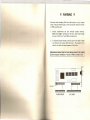
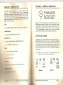
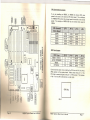
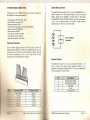
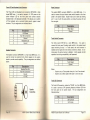
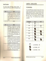
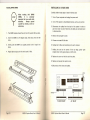
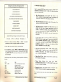
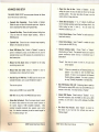
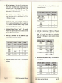
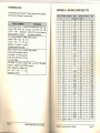
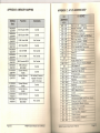
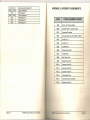
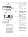
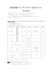
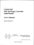
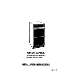
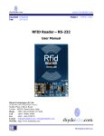
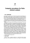
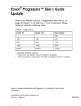
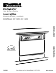
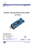
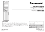
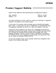
....
"
,
'
.'
'~
'
"
..
,
-.
.
"
,<'
r-
"
I,
,OJ
C
C/)
• '::0
(1)
(J)
<
(ii'
0'
«,
::J
.
.: '
....•.
-<
(f)
~
CD
'3
,
.
'~
~
'
Q.)
'.
...,
.
0..
"
,
'
I,
..
,
'.'
"
..,
.
-
-.
.,
,:
.
..
.
,"
"
C
~
~
ro
<
~
o·
~
~
~
<
rI
ro
m
c
~
~
w
.
~
s
~
00
~
2
3
~
c
~
r-
ro
ro
0
~
.,
CL
~
00
m
~
~
.
..
...
III
!!! WARNING
Be careful while installing
board. Keep the following
a VESA Local Bus card.
VESA Local Bus cards on to your system
tips in mind to properly install and remove
1.
Always
install/remove
the card vertically
straight
down/up.
Never at an angle! Inserting the card at an angle may damage
the pins in both the AT and VESA Local Bus slots.
2.
To install the board vertically, hold the card in the middle. Make
sure that the card is even with both slots.
Then gently fit the
card into the slots with equal pressure at both ends.
Manufacturer warranty does not cover damage caused to the system
board by improper installation or removal of VESA Local Bus cards.
c=:::J
c=:::J
c=:::J
c=:::J
c=:::J
NOTCH---
II
1
iP.?
VL-BUSSLOT
IIMII
IIMII
c=:::J
PIN
1
·
_
1
AT SLOT
1
486SH QUICK REFERENCE
PREFACE
I. STANDARD CMOS SETUP
Date:
Time:
Hard Disk C: Type:
Hard Disk D: Type:
Floppy Drive A:
Floppy Drive B:
Primary Display:
Keyboard:
Current date
Current time
Hord disk parameters
Hard disk parameters
vpo of floppy drive installed
Typo of floppy drive installed
ypo of vidoo card installed
Instollod
Thank you for purchasing the 486SH system board. This document
gives an aid to the configuration and installation of this system
board.
The information
notice.
II. ADVANCED CMOS SETUP
in this document is subject to change without
This document contains information protected by copyright.
All
rights are reserved. No part of this document may be used or
reproduced in any forms or by any means, or stored in a database or
retrieval system, without prior written permission.
TRADEMARKS
Intel is a registered trademark of Intel Corporation.
IBM is a registered trademark of International Business Machines
Corporation.
Microsoft is a registered trademark of Microsoft Corporation.
VESA is a registered trademark of Video
Association.
Electronics Standard
)ijl.il~NO#14QM'# I!i!QM~W::::
Faster
1T
OWlS
3T
2T
1/4 ClK
2T
SYNC
I IIIi'M "Iohlolll 11.11"••1\
I
I
I
I
I
I
I
I
Slower
2T
1 WIS
3T
2T
1/5 ClK
2T
SYNC
I
I
I
I
I
I
I
I
Slowest
2T
1 WIS
3T
2T
1/6 ClK
2T
SYNC
All other trademarks used in this manual are the property of their
respective owners.
I·liobled
1\·86SHSystem Board User's Manual
Page 1
APPENDIX
APPENDIX
APPENDIX
APPENDIX
APPENDIX
TABLE OF CONTENTS
CHAPTER 1: INTRODUCTION
CHAPTER 2: JUMPERS & CONNECTORS
SYSTEM BOARD JUMPERS
CPU External Clock Jumpers
CPU Type Jumpers
Cache Size Jumpers
VESA Local Bus Jumpers
Clear CMOS Data Jumper
Display Type Jumper
Green PC Jumper
YSTEM BOARD CONNECTORS
Power Supply Connectors
External Battery Connector
Keyboard Connector
Power LED and Keyboard Lock Connector
Speaker Connector
Reset Connector
Turbo Switch Connector
Turbo LED Connector
Green PC Connectors
CHAPTER 3: INSTALLATION
THE DRAM SIMMs
Installing DRAM SIMMs
INSTALLING A VL-BUS CARD
EQUIPMENT REQUIRED
CHAPTER 4: BIOS SETUP
ENTERING SETUP
STANDARD CMOS SETUP
ADVANCED CMOS SETUP
POWER MANAGEMENT SETUP
AUTO CONFIGURATION - BIOS DEFAULTS
AUTO CONFIGURATION - POWER-ON DEFAULTS
CHANGE PASSWORD
AUTO DETECT HARD DISK
liARD DISK UTILITY
WRITE TO CMOS AND EXIT
I)() NOT WRITE TO CMOS AND EXIT
I'II"J'I'I~H"
KEYBOARD HOT KEYS
""'II'M
SPEED
4
5
5
7
7
8
8
9
9
A:
B:
C:
D:
E:
AMI BIOS HARD DISK TYPE
MEMORY MAPPING
AT 110 ADDRESS MAP
INTERRUPT ASSIGNMENTS
ENVIRONMENTAL SPECIFICATION
31
32
33
35
36
9
10
10
11
11
12
12
13
13
13
14
15
15
16
17
18
19
19
21
22
26
26
26
26
27
28
28
28
29
29
29
29
30
486SH
"IHlt·'1
1\.86SH System
Board User's Manual
D
System
Board User's Manual,
Page 3
CHAPTER 2: JUMPERS & CONNECTORS
CHAPTER 1: INTRODUCTION
The 486SH system board adds to our 486 product
line high
integration
and cost
effective
solution
without
compromising
performance and quality.
With top speed at 50MHz and integrated
64K/128K/256K
Write-Back cache, the 486SH dramatically
boosts
system throughput
for even the most demanding applications.
The
486SH offers features and functionality
exceeding any other system
When working with the 486SH,
it is extremely
important
that
you
avoid
static
electricity.
Always
ground
yourself
by
wearing a wrist or ankle strap.
board in its class, including:
CPU:
•
Intel i486DX,
i486DX2,
i486SX,
i487SX,
P24T, and Overdrives.
Cache Memory:
•
Supports
64KI1 28K/256K
Figures 1 on the next page shows the component layout of the
486SH system board with locations of the system board jumpers
and connectors.
Note that most jumpers and connectors on the
system board are labeled with proper names with pin 1 marked as
'1'. To avoid damaging the board and to have proper operation
caution should be taken when connecting these components.
cache memory.
SYSTEM BOARD JUMPERS
Main Memory:
•
Supports
256Kx9,
1Mx9, and 4Mx9
•
Up to 32 MBytes on-board memory.
SIMM modules.
Slots:
•
Three 32-bit VESA Local Bus slots.
•
Six 16-bit ISA bus slots.
•
one 8-bit ISA bus slot.
Note:
ruun PC:
I I'll
.Io(:k slow-down
and monitor
Jumpers are used to select between various operating modes.
A
jumper switch consists of two, three, or four gold pins projecting
from the system board. Placing the plastic jumper cap over two pins
connects those pins and makes a particular selection.
Using the cap
to cover two pins in this way is referred to as shorting those pins. If
the cap is not placed on any pins at all, this is referred to as leaving
the pins open.
shut-down
features.
When you open a jumper, leave the plastic
attached to one of the pins so you don't lose it.
I ~U
OPEN
,I
I'IHIII'I
PINS 1-2
SHORTED
SHORTED
2-pin jumper
1\11I11
cap
Il:l o
ttory:
n 1\
jumper
3-pin jumper
d be ttery.
1\ 06SH System Board User's Manual
486SH pystem
Board User's Manual
Page 5
CPU External
~ !S
~
lUJ
0
:l!8
I
~,..,
~~
-0
Q.",
~O>
o
Oc:
r
;~
b~
~
oOt)
ITl
\@
00
I
~@
~
rn
,
-,
.":i
o UUUUUUUU
· ~tOOLJ LJ LJ LJ [IJ OJ ~
J:~C/)
\
\
.,.
tEl~
~..
~~.
Q.)U~
-ncuE
_Q.
~~~ / ::"
I
I
"I
'.
tHJ
.••.
.
M
@
1
>-
<~ ~
<~:;;
[;I!llI.l
'ffiS"
~~
~
<~
<
I
I
CD
~;:
n. •••
-
G?
r---l
I\
~
<
I
a
<
,
SHORT
1-2
SHORT
OPEN
1-2
33MHz
SHORT
OPEN
OPEN
1-2
40MHz
OPEN
SHORT
OPEN
2-3
50MHz
OPEN
OPEN
OPEN
2-3
=~
~~
oo~
-.:r
•• E-t
~z
CPU Type Jumpers
'QRYmyp'glqRl§·1·4R1fil·4R1.§"I,~R1.ft,
486DX,
487SX,
I
1-2
I
1-2
I
SHORT
I
SHORT
I
1-2
I
2-3
I
SHORT
I
SHORT
I
I
2-3
2-3
I
I
OPEN
OPEN
I
I
OPEN
OPEN
I
I
SHORT
OPEN
486SX
QFP486SX
~~
C,!)~
U
486DX2
ODP486SX
Care should be taken when installing the CPU into the Pin Grid Array
(PGA) socket on the system board.
Make certain that pin 1 of the
CPU chip is correctly aligned with pin 1 of CPU socket.
The location
of pin 1 on the CPU is denoted by a small notch.
I
r;,;,~~l\
~1?I:'j.'
OPEN
SHORT
~~
I
\
I
OPEN
25MHz
CJI
\
\
5
;;::J
-rz ~0
~:.:.~ ~:'!
20MHz
E-t
@
~ ~:'i
( ~ en~ • ~
'1
~
co
N
lilllll~llfl;l
0
-----
------
~........
';;;:o:~
~§Q)
If you are installing
an i486DX,
or i486SX the internal CPU clock
speed is the same as the external CPU clock speed. This is different
for i486DX2 CPU where the external speed is one-half of the internal
speed.
For example, a 486DX2-66
has an external clock speed of
33MHz.
...i!rn~~
@I
~
Clock Jumpers
\
\
I
I
I
CPU Chip
\
\
~
n
Pin 1
~
I"HI"
,
"BOSI t System Board User's Manual
486SH
System
Board User's
Manual
Page 7
Clear CMOS Data Jumper
Cache Size Jumpers
The system board supports 64KB/ 128KB/ 256KB of cache memory.
128KB
256KB
1-2
1-2
2-3
I
I
I
I
I
2-3
1-2
2-3
I
The CMOS jumper JP10 is used to clear the system configuration
data currently stored in the CMOS RAM.
All system setup
information (hard disk type, date/time, etc ... l. stored in the CMOS,
will be destroyed.
This function would be useful if you were to
forget the user password for the system.
·~e1g
1-2
2-3
2-3
I
I
1-2
(Default)
2-3
Clear CMOS Data
Cache Size and SRAM Locations
·•··rlill~
•• ••••I•·I~IIII·tl'II.IIII~IIE,'111Iilll·.·.
••
64KB
128KB
256KB
I
I
I
8Kx8
32Kx8
32Kx8
I
I
I
8Kx8
32Kx8
32Kx8
I
I
I
Display Type Jumper
8Kx8
None
32Kx8
(leI
Video
display
is VGA,
Monochrome.
Video display is CGA.
EGA,
or
OPEN
(Default)
SHORT
VESA Local Bus Jumpers
Jumper JP4 allows any VL-Bus adapter to identify the speed of the
system board.
m•.gn·$.p~g4.Wri!ij..fJll
System board runs one wait state write
2-3
transfer.
All VL-Bus adapters can (Default)
operate in this mode.
System board runs zero wait state write I
1-2
transfer.
Some VL-Bus adapters may
nor be able to run this mode.
l'tHlo U
486SH System Board User's Manual
Green PC Jumper
PC clock-slow-down
control.
During specified idle period,
CPU clock is slowed down to 8-MHz to
conserve power.
Disable Green PC clock-slow-down I
control. CPU is always running at full
speed.
486SH System Board User's Manual
OPEN
Page 9
External Battery Connector
SYSTEM BOARD CONNECTORS
Following is the list of 486SH system board connectors required to
be installed for proper system operation.
-
Power supply connectors (CN1, CN2)
External battery connector (J1)
Keyboard connector (KB1)
Power LED and keyboard lock connector (KEYLOCK)
Speaker connector (SPEAKER)
Reset connector (RESET)
Turbo switch connector (TB SW)
Turbo LED connector (TB LED)
Green PC Connectors (JP8, JP50)
The external battery connector (J1) is a 4-pin keyed BERGstrip. It is
used to connect + 4. 5 Volt external battery (in case the on-board
battery capsule is not installed) to provide power to the system
board Real-Time Clock and CMOS memory when the system power
is off.
For an external battery, the battery's cable connector
attaches to pin 1 and 4 of J 1 as shown below.
+
Battery
External Battery
Connection
Power Supply Connectors
The two Power Supply connectors, CN1 andCN2, are 6-pin AT
standard power connectors. Most power supplies have two six-wire
connectors, two of the wires on each connector are black. Align the
two six-wire connectors so that the two black wires on each
connector are in the middle as shown below.
Keyboard Connector
The keyboard connector is a 5-pin, circular-type DIN socket. It is
used to connect the system board keyboard interface to any
standard AT-compatible keyboard (84 or 101 -kev type keyboards).
The pin assignment is shown below:
:I§§prippgp(
;:;;;;;:jii:::i:i;i:i:§gnOgRjgrQN~::IP;pop~q!Qr~lg//
Pin
Ii
~I
j'
Phil'} 10
Power Good
+ 5 VDC
+ 12 VDC
12 VDC
_
Ground
~rtlund
I
I
I
I
I
2
3
4
5
Keyboard Clock Signal
Keyboard Data Signal
Not Used
Ground
+ 5V Fused VDC
Ground
Ground
-5 VDC
+ 5 VDC
+ 5 VDC
+ 5 VDC
486SH System Board User's Manual
486SH System Board User's Manual
Page 11
Power LED and Keyboard Lock Connector
Reset Connector
The Power LED and Keyboard Lock connector (KEYLOCK) is 5-pin
keyed BERG strip.
It is used to connect + 5 VDC power to the
power indicator LED at the front panel and connect security
keyboard lock to the keyboard controller. This allows you to switch
off the keyboard and so provide limited security against casual
intruders. The pin assignments are indicated below:
The system RESET connector (RESET) is a 2-pin BERG strip. It is
used to connect the push button reset switch located on the front
panel to the system board. System reset can be done by shorting
pin 1 to pin 2 with the same effect as turning the power off and
then on again.
::tl~'Gt~it~qn}
Reset Input
Ground
1~§G!~p~gp:r
1
2
3
4
5
I
I
I
I
I
LED Power
Key (No Connection)
Ground
Keyboard Lock
Ground
Turbo Switch Connector
Speaker Connector
The Speaker connector (SPEAKER)is a 4-pin keyed BERGstrip. It is
used to connect an external 2-inch, 8-ohm speaker to the system
board to provide sound capability. The pin assignments are defined
below:
The Turbo switch (TB SW) is a 2-pin BERG strip. It is used to
connect the front panel 2-position push switch to the system board
speed switching circuitry.
In Turbo speed, the cache memory is
enabled and full speed of 32-bit memory transfer is utilized. In nonturbo speed, the cache memory is disabled. In both speeds, the ISA
expansion bus timing compatibility is still preserved.
:::J.;nt~qtJ,Pt~gntt
Turbo Speed
Ground
:[I~9.dptignt
Notes:
Speaker Data Out
Key (No Connection)
Ground
+5 VDC
2
3
4
System runs at Turbo speed when pins 1 and 2 are shorted.
System runs at Slow speed when pins 1 and 2 are open.
Turbo LED Connector
- --
1
2
3
l1
Speaker
Connection
The Turbo LED connector, marked as 'TB LED', is a 2-pin BERGstrip.
It is used to connect a CPU operating frequency indicator LED from
the front panel to the system board. The pin assignments are
indicated below:
.····:tlg!l!iy9Q::::ji
LED Cathode
LED Anode
l'fllN I
486SH System Board User's Manual
486SH System Board User's Manual
Page 13
Green PC Connectors
CHAPTER 3: INSTALLATION
This function requires AMI Megakey keyboard controller.
To
program the Green PC feature, use BIOS Power Management Setup.
THE DRAM SIMMs
::~:::::p~Q8E
1
Keyboard P11.
Use this pin for controlling
general purpose Green PC device. When signal
on this pin goes low, the external Green PC
device connected to this pin should go into
power saving state.
This pin must be
programmed through BIOS Power Management
Setup.
Ground
2
The on-board DRAM memory subsystem has eight module mounting
sockets which are divided into "banks' of four sockets each. These
banks are labeled Bank 0 and Bank 1. Single In-Line Memory Module
(SIMM) added to these banks must be installed a full bank at a time.
Start with bank 0, then work your way up. DRAM speed must be
80ns, 70ns, or 60ns. You can configure the memory of the 486SH
in a variety of ways.
The chart below shows the possible
combinations.
'£9!~J.N!~19rY~::I'QR~f
1MB
~·::··:·I~rf·:::::?
1
2
3
1'/HIIl
1
Keyboard P12. Connect this pin to the Video
card's Feature Connector (also called VGA
Pass-Through connector) Sync Enable pin 18.
During power saving mode (if enabled through
system BIOS), signal on this pin goes low to
turn OFF the Vertical/Horizontal Sync going to
the display monitor to conserve power. This
pin must be programmed through BIOS Power
Management Setup.
Keyboard P13.
Use this pin for controlling
general purpose Green PC device. When signal
on this pin goes low, the external Green device
connected to this pin should go into power
saving state.
This pin must be programmed
through BIOS Power Management Setup.
Keyboard P15.
Use this pin for controlling
general purpose Green PC device. When signal
on this pin goes low, the external Green device
connected to this pin should go into power
saving state.
This pin must be programmed
through BIOS Power Management Setup.
486SH System Board User's Manual
2MB
4MB
8MB
20MB
16MB
32MB
UfO
•
rrr.
UfO
UfO
UfO
•
•
•
rrr.
•
rrr.
rrr.
rrr.ii
Four 256KB SIMMs = 1MB
Four 1MB SIMMs
=
4MB
Four 4MB SIMMs
=
16MB
486SH System Board User's Manual
Page 15
INSTALLING A VL-8US CARD
Installing DRAM SIMMs
Carefully follow these steps to install a VL-Bus card:
When
working
with
DRAM
SIMMs,
it
is
extremely
important that you avoid static
electricity.
Always
ground
yourself by wearing a wrist or
ankle strap.
1.
The SIMM modules should face to the left towards
2.
Insert the SIMM at a 45 degree angle, tilted away from the ISA
slots.
1. Turn off your computer
and unplug the power cord.
2. Turn off the power to all peripheral devices, such as your printer.
3. Disconnect the cables from the back of the system in order to
give more room to work. Note how all cables are connected prior
to disconnection.
ISA bus slots.
4. Remove the computer's
3.
Gently push the SIMM to an upright position until it "snaps" into
place.
4.
Repeat above steps until the entire bank is filled.
cover.
5. Choose an unused VL-Bus slot.
6. Setting the VL-Bus card according to its user's manual.
7. Holding the card at the center of the top edge,
straight down with equal pressure at both ends.
gently
push
8. Replace the screw to hold the card into place.
9. Replace and secure the system cover.
1a.Reconnect
}
all the wires and cables.
I~c:=J
c:=J
c:=J
II ---c:=J
_00000000000001
NOTCH-------
1
PIN
1
486SH System Board User's Manual
•
I
VL-BUS SLOT
p
1
486SH System Board User's Manual
AT
1
SLOT
Page 17
.EQUIPMENT
REQUIRED
CHAPTER 4:
The dimension
of the 486SH system board is designed to fit
perfectly in a PC/XT (or PC/AT) standard case. To build a complete
high performance
system based on the 486SH system board, the
following
equipment
You need to setup a system once every time:
are needed:
A chassis with dimension
similar to PC/XT/AT
•
You start a new and unconfigured
transmission.
A 2-inch, 8-0hm
A push button
One floppy
speaker to provide sound capability.
switch
with a 2-pin connector
switch
with 2-pin connector
system.
•
You receive a start-up error message indicating the configuration
information
stored in the non-volatile CMOS RAM has somehow
become corrupted.
•
You add, remove or change peripherals from your system.
standard chassis.
A standard AT 220W power supply which is capable to provide a
continuous power within a + 4.85 VDC to + 5.25 VDC range. A
power
line filter
may
be needed
for
areas with
noisy
A 2-position
BIOS SETUP
for speed function.
for reset function.
The first
time
you
power
up the system,
the configuration
information
stored in the battery-backed
CMOS RAM may not be
correct.
The BIOS detects this condition and prompts user to go
through the SETUP section.
This chapter explains how to use the
BIOS SETUP program and make the appropriate entries.
drive (360K or 1.2M or 1.44M).
Some of the parameters
are
already factory
preset and do
not need to be changed. Please
read the instructions
carefully
and only change the settings if
necessary.
Hard disk drive.
A combinational
hard disk and floppy disk controller
A video card (Monochrome,
card.
CGA, EGA, VGA).
A set of flat cables between
floppy
drive and hard disk drive to
the combinational
controller
card.
An AT-compatible
keyboard
(84 or .101 Keyboard) with cable.
ENTERING SETUP
A video display monitor.
Following
additional
equipment
will be useful to enhance the system:
1. Reset the system by turning it OFF then
"RESET" button on the system front panel.
2. Hit the
< Del>
message appears:
A bus or serial mouse.
key
momentarily
as
ON or pushing
soon
as the
the
following
A tape pack up drive.
"Hit
< DEL>,
3. After you press the
appears:
18
486SH
System Board User's Manual
if you want to run SETUP"
< Del>
key, the following
486SH System Board User's Manual
BIOS Setup screen
Page 19
AMI BIOS SETUP PROGRAM - BIOS SETUP UTILITIES
(C) 1992 American Megatrends Inc., All Rights Reserved
STANDARD CMOS SETUP
Use the standard CMOS Setup screen to check or modify general
configuration
information
such as the date, time, floppy type, hard
disk type, video type, etc.
STANDARD CMOS SETUP
ADVANCED CMOS SETUP
POWER MANAGEMENT
i
SETUP
;
AUTO CONFIGURATION
AUTO CONFIGURATION
•
Date (Month/DatelYear):
On the bottom
right corner of the
screen, a calendar has been provided for user. You manually set
the electronic calendar only if the values are incorrect.
•
Time (Hour/Minute/Second):
The time here is 24-hour
would enter 5:30 P.M. as 17:30:00.
•
Hard Disk C:/D: Type: The BIOS provides 46 predefined types of
popular hard disk drives.
Relevant specifications
include the
number of cylinders and heads, write pre-compensation
time,
read/write
head landing zone, number of sectors per track.
A
hard disk will not work properly if your enter incorrect drive
parameters.
•
WITH BIOS DEFAULTS
WITH POWER-ON DEFAULTS
CHANGE PASSWORD
AUTO DETECT HARD DISK
HARD DISK UTILITY
WRlTE TO CMOS AND EXIT
DO NOT WRlTE TO CMOS AND.f:XIT
time.
You
Standard CMOS Setup for Changing Time, Date, Hard Disk Type, etc.
I
ESC: Exit
..j..~t~: Sel
F2/F3: Color
FIO: Save & Exit
4. Choose an option
and press < Enter> .
Modify
the
parameters to reflect the options installed in the system.
5. Press < Esc > at anytime
If your particular drive is not one of the 46 pre-defined types,
simply scroll down to select type 47 and enter the appropriate
values for cylinders, heads, WPcom, LZone, and sectors.
Size is
automatically
determined by the other entries.
You can also let
the BIOS to determine
the drive type by selecting
"AUTO
DETECT HARD DISK" from the Main Menu.
I
system
to return to the Main Menu.
6. In the Main Menu, choose "WRITE TO CMOS AND EXIT" to save
your changes and reboot the system.
Choosing "DO NOT WRITE
TO CMOS AND EXIT" ignores your changes and exits the BIOS
SETUP program.
In each setup screen,
be used:
<F1 >
<F2>,
<F3>
<F5>
<F6>
<F7>
<ESC>
Arrow Keys
<PG UPI PG DN>
p
20
the following
common
keyboard
controls
Floppy Drive A: Type (360KB, 720KB, 1.2MB, 1.44MB, 2.88MB,
or Not Installed):
Specify the type of the first floppy drive
installed on the system.
'Not Installed' could be used as an
option for diskless workstations.
•
Floppy Drive B: Type:
Specify
drive installed on the system.
•
Primary
Display
Monitor
(Color
40x25,
Color
80x25,
VGA/PGA/EGA,
Monochrome):
The 'Not Installed' option could
be used for network file servers.
may
Help
Color (to change screen color)
Old Setup Values
BIOS Setup Default Values
Power On Default Values
Exit Setup Section
Select Setup Item
Modify the Setup Item
486SH
•
'.
486SH
~
of the second
Keyboard (Installed / Not Installed): Default is "Installed".
Installed" allows your system to operate without keyboard.
After all selections
section.
System Board User's Manual
the type
have been done, press
System Board User's Manual
< Ese>
floppy
"Not
key to exit this
Page 21
•
ADVANCED CMOS SETUP
"ADVANCED CMOS SETUP" lists some system features
you to fine tune your system setup.
that allows
•
Typematic Rate Programming:
Choose Enabled or Disabled.
Enable this option to adjust the keystroke repeat rate. Adjust the
rate via Typematic Rate Delay and Typematic Rate.
•
Typematic Rate Delay:
a key and when the
500milliseconds.
•
Typematic Rate: Choose the rate a character
Default is 15 characters per second.
•
Above 1MB Memory Test:
Default is "Disabled" to speed up
power-on initialization
process and the BIOS will only test the
extended memory every 32K locations only to determine the onboard memory size.
•
Memory Test Tick Sound:
sound during memory test.
•
Memory Parity Error Check: Default is "Enabled"
transmission errors in data read from memory.
•
Hard Disk Type 47 RAM Area: The BIOS uses this area to store
extended information,
such as user definable drive type 47.
Choose the delay between holding down
character
begins repeating.
Default is
Default
is "Enabled"
keeps repeating.
test
System Boot-Up Sequence:
If "A:, C:" (default), the BIOS will
look for bootable operating system files from floppy drive A: first
before looking for them
in drive C:.
You can reverse this
sequence by selecting "C:, A:".
•
External Cache Memory:
board cache memory.
•
Internal Cache Memory:
Select "Enabled"
memory inside the 486 CPU chip.
•
for
Select "Enabled"
to enable external
on-
to enable the cache
Password Checking Option:
Choose "Setup"
or "Always".
default setting is "Setup".
The password feature can be used to
prevent unauthorized
system boot-up or unauthorized
use of
BIOS SETUP.
"Always"
Each time the system
prompt appears.
is turned
on, the
pass word
"Setup"
If there is a password set, the Password prompt only
appears if you attempt
to enter the BIOS Setup
program.
If there is no set password, the Password
Checking Option is disabled.
You create a password
by using "CHANGE PASSWORD" in the Main Menu.
•
Video ROM Shadow COOO, 32K:
Shadowing helps to speed up
BIOS access by copying BIOS code to fast 32-bit RAM area and
executes it from there. The default setting is "Enabled".
DOS 1KB in the top 1 KB of the 640KB DOS base memory
•
System Boot Up NumLock: When the computer boots, it selects
the numeric values rather than the cursor control functions on
the numeric
keypad of IBM compatible
keyboards.
Most
extended
compatible
keyboards
have separate cursor control
keys. It is therefore unnecessary to use the numeric keypad for
this. The default setting is "On".
Adapter ROM Shadow:
Default setting is "Disabled".
If you
have other expansion cards with ROMs on them such as SCSI
controller,
you will need to know which addresses the ROMs
use.
•
Boot Sector Virus Protection:
Select 'Enabled'
Boot sector of your hard disk from software
"Michael Angelo".
There are two options:
Default option
•
•
for the ticking
to
Floppy Drive Seek At Boot:
Default is "Disabled".
On this
setting the system will check the hard disk first to find the disk
operating system.
This option also allows the user to run the
system without a floppy disk drive.
Pogo 22
is 0:300
in lower system RAM
486SH
System Board User's Manual
486SH System Board User's Manual
to protect the
virus such as
Page 23
•
IDE Block Mode Transfer: Some latest IDE hard disks support
multiple sector (Block Mode) transfer for faster performance.
Users select "Enabled" to take advantage of this feature. If your
system hard disk supports Block Mode, BIOS message "Block
Mode Enabled" will appear during boot-up.
•
~11~~lil!piil..·!!!!!:!!!J~i~i~RiIMrit··
'I
•
•
•
•
IDE Standby Mode: Default is "Disabled".
If this feature is
enabled, IDE hard disk will go into Standby Mode to save power
in 15 minutes of no access.
Auto Key-Lock Time-out: Default is "Disabled". Keyboard will
lock up to prevent unauthorized access after an idle period from
1 to 15 minutes. This feature is enabled by setting up system
Password and selecting number of minutes.
Cyrix Suspend Feature: Default is "Disabled". 486 compatible
CPUs from Cyrix support Suspend Feature that allows a dramatic
reduction in CPU power consumption.
~::i§Y9!:::·[email protected]¥i!ft:i
~
20MHz or 25MHz
33MHz with 64KB or
256KB Cache
33MHz with 128KB
cache
,
.1;
,
40MHz
50MHz
•
Slower
Slower
Slowest
I
1T
1T
2T
2T
I
DRAM Hidden Refresh:
performance.
0 W/S
25MHz
33MHz
40MHz
1 W/S
1 W/S
1 W/S
50MHz
Select "Enabled" to maximize system
2T
3T
3T
I
2T
2T
I
"1/2 ClK = 1OMHz or
1/3 ClK = 6.67MHz
1/3 ClK = 8.33MHz
1/4 ClK = 8.33MHz
1/4 ClK = 10MHz or
1/5 ClK = 8M Hz
1/5 ClK = 10MHz or
1/6 ClK = 8.33MHz.
Latch Local Bus Device, Local Bus Ready: Follow below table to
set these options.
!::~::::~~!:~~::Ji:!i~1;i==:III.~I'~
20MHz
25MHz
33MHz
40MHz
50MHz
Page 24
3T
ISA Bus Clock: Default setting is 7 .16MHz for any CPU speed.
latest ISA adapters may operate with ISA bus clock speed up to
10MHz. ISA bus speed above 10MHz is not recommended.
Different than 7. 16MHz speed can also be selected by following
below table.
20MHz
•
•
I
1T
1T
·:Rlg.gJ.gG~:lpm!~:~~:I$.~IYilJ.PQ~rI
••"I-i!II_11
Fastest
I
2T
3T
~
DRAM Speed, DRAM Write CAS Pulse, DRAM Write Cycle:
Select these options according to table below:
20MHz or
25MHz
33MHz
40MHz
50MHz
Cache Write Cycle, Cache Burst Read Cycle: Follow below table
to set these Cache options.
486SH System Board User's Manual
2T
2T
2T
2T
2T or 3T
486SH System Board User's Manual
TRANS
TRANS
SYNC
SYNC
SYNC
Page 25
POWER MANAGEMENT SETUP
I Enter NEW Password:
The Power Management Setup provides a programming way to slow
down CPU clock speed and put other system devices such as Video
Monitor into power saving mode.
If you want to disable the password
key to return to the Main Menu.
There are five software
timers internal to the MEGAKEY keyboard
controller
that perform
power management.
These timers are
initialized by BIOS with user-defined time-out values from 1 to 255
minutes.
The I/O pins that are associated with each timer are
hardware design-specific
and are defined as connectors
JP8 and
JP50 on the 486SH motherboard.
Please refer to Chapter 2 for
detailed description of these connectors.
3.
CPU and devices connected to JP8 and JP50 will go in to power
saving mode if the keyboard is not used by user for a period of time
programmed through this BIOS option.
4.
option,
just press <Enter>
If this option has been used to enter the password,
will display the following message:
the screen
I Enter Current Password:
Enter the current
screen instructions
password
(default is AMI)
to change the password.
and
follow
After you correctly
enter the current password, the
message appears prompting you for the new password.
the
following
I Enter NEW Password:
AUTO CONFIGURATION WITH BIOS DEFAULTS
5.
Use this option to load the default configuration
values directly from
ROM. If the stored record created by the Setup program becomes
corrupted, these defaults will load automatically
when you turn the
computer on.
I Re-Enter
6.
1.
Choose "CHANGE
press < Enter> .
2.
If this option has never
following message.
Page 26
PASSWORD"
from the Setup Main Menu and
been used, the screen will
486SH
display
the
System Board User's Manual
Re-enter the new password.
If the password
following error message appears:
is mis-keyed,
the
the following
confirmation
0
I NEW Password
7.
Note that the pass
message appears:
NEW Password:
If the password is keyed in correctly
message appears:
Use this option to load the settings detected by the system when
you turn it on. It your system behaves erratically you can use this
feature to check for incorrect settings.
Follow these steps to change system password.
word cannot be longer than 6 characters.
and the following
I ERROR, Press Any Key ...
AUTO CONFIGURATION WITH POWER-ON DEFAULTS
CHANGE PASSWORD
Enter the new password
Press <Ese>
Installed
to exit to the Main Menu.
AUTO DETECT HARD DISK
Use
type
will
you
this BIOS utility to automatically
detect popular IDE hard disk
if it is not readily available.
It is not guaranteed than this utility
work with all IDE hard disk. There is no need to use this utility if
already have hard disk type information.
486SH System Board User's Manual
Page 27
HARD DISK UTILITY
CHAPTER 5:
Use this option to do low-level hard disk format, Auto-Interleave
and
Media-Analysis
of your MFM harddisk drive.
IDE, ESDI, and SCSI
drives don't need this utility and you should not use it on them.
Low-level harddisk format should be done for new harddisks and
should be done yearly for used harddisks.
This format function
allows you to format the entire disk or a part of the disk. Warning!
All data on the hard disk may be lost after a low-level format.
SYSTEM SPEED
System speed can also be changed through
two available speeds as shown below:
Turbo speed:
With Auto-Interleave
you need not speculate about the value of the
interleave factor while entering the parameters for format.
This
function determines the optimum interleave factor for the best disk
performance.
Media Analysis
does a comprehensive
analysis of the harddisk
surface to find out bad patches on your harddisk.
This leaves the
surface of the harddisk formatted with bad tracks marked bad.
WRITE TO CMOS AND EXIT
KEYBOARD HOT KEYS
Cache
< Ctrl
»,
DO NOT WRITE TO CMOS AND EXIT
After you have/have
not made any changes during setup and
decided not to store those information
into non-volatile
CMOS
memory, use this option to exit Setup.
The system should reboot
with the current configuration
stored in CMOS memory.
»,
< Alt
~
Slow speed:
and 32-bit
Set by pressing
OFF.
<Ctrl>,
<
DRAM transfer
+>
<Alt
>,
< -
holding
keys.
DRAM transfer
>
and <Shift>
+ ~
mode are
+ ~Shift~ + ~
and 32-bit
Set by pressing
There are
key once while
and < Shift>
+ ~
Cache memory
~
After you have made any changes during setup, use this option to
store those new information
into non-volatile CMOS memory.
The
system should reboot with the correct system board configuration.
memory
ON.
keyboard.
mode are
key once while
holding
keys.
+ ~Shift~ +
g
SYSTEM SECURITY LOCKING
The default hot key sequence is < Ctrl > < Alt > < Backspace> .
When the System Password feature is enabled in BIOS Setup, the
user can invoke this feature at any time by pressing this key
sequence.
This feature is useful for preventing unauthorized access
to the system.
Once system locking is invoked, the keyboard does
not accept anything from the keyboard until the correct password is
entered.
The Num Lock, Caps Lock, and Scroll Lock LEOS blink
when the system is password locked.
SYSTEM POWER DOWN MODE
Pressing <Ctrl>
<Alt>
<V> key sequence puts the system into
immediate power down mode. This hot key sequence is active if the
Green PC system power saving mode is enabled in BIOS Setup.
Page 28
486SH
System Board User's Manual
486SH System Board User's Manual
Page 29
PASSWORD STATE
APPENDIX A: AMI BIOS HARD DISK TYPE
The table below lists the Green PC (power saving) hot key sequence
and the state of Password in various modes.
,:;;;:§Y~t~mg§n4.w§n!':.';:lijfgrmijt~gn:::;?
The password feature is enabled
through
BIOS Setup
and the
< Ctrl > < Alt > < Backspace>
hot key sequence is pressed.
The password feature is enabled
through
BIOS Setup
and the
< Ctrl > < Alt > < \ > hot key
sequence
is pressed to invoke
immediate power down mode.
Both the Green PC power savings
feature and the password feature
are enabled.
The system goes to
power down state after the timeout period expires.
The Green PC power
savings
feature is enabled through BIOS
Setup, Password is disabled and
the
< Ctrl > < Alt > <\ > key
sequence is pressed.
I
The Keyboard Num Lock, Caps
Lock,
and Scroll
Lock LEOs
blink until the correct password
is entered via keyboard.
Same as above.
I Same
I
as above.
Press any
operation.
key
for
full
power
m¥ei;J9Y~i~~rl·illlll~r'll~iii'~~li'iiI1]1~~~~I:1
2
3
4
5
6
7
8
9
10
11
12
13
14
16
17
18
19
20
21
22
23
24
25
26
27
28
29
30
31
32
33
34
35
36
37
38
39
40
41
42
43
306
615
615
940
940
615
"462
733
900
820
855
855
306
733
612
977
977
1024
733
733
733
306
925
925
754
754
699
823
918
1024
1024
1024
612
1024
1024
615
987
987
820
977
981
830
4
4
6
8
6
4
8
5
15
3
5
7
8
7
4
5
7
7
5
7
5
4
7
9
7
11
7
10
7
11
15
5
2
9
8
8
3
7
6
5
5
7
I
I
I
I
I
I
I
I
I
I
I
I
I
I
I
I
I
I
I
I
I
I
I
I
I
I
I
I
I
I
I
I
I
I
I
I
I
I
I
I
I
I
128
300
300
512
512
65535
256
65535
65535
65535
65535
65535
128
65535
0
300
65535
512
300
300
300
0
0
65535
754
65535
256
65535
918
65535
65535
1024
128
65535
512
128
987
987
820
977
981
512
I
I
I
I
I
I
I
I
I
I
I
I
I
I
I
I
I
I
I
I
I
I
I
I
I
I
I
I
I
I
I
I
I
I
I
I
I
I
I
I
I
I
305
615
615
940
940
615
511
733
901
820
855
855
319
733
663
977
977
1023
732
732
733
336
925
925
754
754
699
823
918
1024
1024
1024
612
1024
1024
615
987
987
820
977
981
830
17
17
17
17
17
17
17
17
17
17
17
17
17
17
17
17
17
17
17
17
17
17
17
17
17
17
17
17
17
17
17
17
17
17
17
17
17
17
17
17
17
17
17
17
TYPE
486SH
System Board User's Manual
10MB
20MB
31MB
62MB
47MB
20MB
31MB
30MB
112MB
20MB
35MB
50MB
20MB
43MB
20MB
41MB
57MB
60MB
30MB
43MB
30MB
10MB
54MB
69MB
44MB
69MB
41MB
68MB
53MB
94MB
128MB
43MB
10MB
77MB
68MB
41MB
25MB
57MB
41MB
41MB
41MB
114MB
152MB
APPENDIX B: MEMORY MAPPING
APPENDIX C: AT 1/0 ADDRESS MAP
(:.·:.···.!:!tl.··.
1
·:II!I!II·
••••••••
··I~'I~I
•••••••
000000000007FFFF
000800000009FFFF
OOOAOOOOOOOBFFFF
OOOCOOOO000C7FFF
000C8000OOOCFFFF
OOODOOOOOOODFFFF
OOOEOOOOOOOEFFFF
OOOFOOOOOOOFFFFF
00100000OOBFFFFF
OOCOOOOOOOFFFFFF
01000000BFFFFFFF
COOOOOOOC1 FFFFFF
C2000000FFFDFFFF
FFFEOOOOFFFFFFFF
Page 32
:::fH§~)
51 2K System RAM
Cached
128K System RAM
Cached
128K Video RAM
Not Cached
32K Video BIOS
Cached
32K I/O ROM
Not Cached
64K I/O ROM
Not Cached
64K Extended BIOS
Not Cached
64K On-Board
BIOS ROM
System Memory
(RAM)
System Memory
(RAM)
System Memory
(RAM)
System Memory
(RAM)
System Memory
128K On-Board
BIOS ROM
Cached
Cached
Not cached if memory
mapped I/O board is
used in this range
Cached
Cached
Cached
Not cached
486SH System Board User's Manual
000 - 01 F
020 - 03F
040 - 05F
060 - 06F
070 - 07F
080 - 09F
OAO - OBF
OCO - ODF
OFO - OFF
1FO - 1F8
200 - 207
20C - 20D
21F
278 - 27F
2BO - 2DF
2E1
2E2 - 2E3
2F8 - 2FF
300 - 31 F
360 - 363
364 - 367
368 - 36B
36C - 36F
378 - 37F
380 - 38F
390 - 393
3AO - 3AF
3BO - 3BF
3CO - 3CF
3DO - 3DF
3FO - 3F7
3F8 - 3FF
6E2 - 6E3
790 - 793
AE2 - AE3
B90 - B93
DMA Controller 1, 8237 A-5
Interrupt Controller 1, 8259A
System Timer, 8254-2
8742 Keyboard Controller
Real-Time Clock/CMOS and NMI Mask
DMA Page Register, 74LS612
Interrupt Controller 2, 8259A
DMA Controller 2, 8237 A-5
CPU's Internal Math Coprocessor
Fixed Disk Drive Adapter
Game I/O
Reserved
Reserved
Parallel Printer Port 2
Alternate Enhanced Graphic Adapt
GPIB Adapter 0
Data Acquisition Adapter 0
Serial Port 2 (RS-232-C)
Prototype Card
C Network (Low Address)
Reserved
PC Network (High Address)
Reserved
Parallel Printer Port 1
SDLC, Bisynchronous 2
Cluster
Bisynchronous 1
Monochrome Display and Printer Ado()t(
Enhanced Graphics Adapter
Color/Graphics Monitor Adapter
Diskette Drive Controller
Serial Port 1 (RS-232-C)
Data Acquisition Adapter 1
Cluster Adapter 1
Data Acquisition Adaptor 2
Cluster Adapter 2
.11l0SH System Board User's Manual
EE2 - EE3
1390 - 1393
22El
2390 - 2.393
42El
62El
82El
Data Acquisition Adapter 3
Cluster Adapter 3
GPIB Adapter 1
Cluster Adapter 4
GPIB Adapter 2
GPIB Adapter 3
GPIB Adapter 4
APPENDIX D: INTERRUPT ASSIGNMENTS
·i::miIJQI~'iN:1188IBmlgQi~eI
NMI
Parity, AT Channel Check
IROO
Interval Timer 1, Counter 0 Out
IROl
Keyboard Controller
IR02
Cascade Interrupts from IR08 to IR015
IR03
Serial Port 2
IR04
Serial Port 1
IR05
Parallel Port 2
IR06
Diskette Controller
IR07
Parallel Port 1
IR08
Real Time Clock
IR09
Expansion Bus Pin
IR010
Expansion Bus Pin
IROll
Expansion Bus Pin
IR012
Expansion Bus Pin
IR013
Coprocessor Error
IR014
Fixed Disk Drive Controller
IR015
Expansion Bus Pin
'\
Page 34
486SH System Board User's Manual
IIIIIH t :lYII! uII
1
Board User's Manual
PI;l!lO ~31)
APPENDIX E: ENVIRONMENTAL
SPECIFICATION
TEMPERATURE RANGE
Operating:
500 to 104° Fahrenheit (10° to 40° Celsius)
.:
Non-Operating:
50° to 104° Fahrenheit (10° to 40° Celsius)
Shipping:
-22° to 140° Fahrenheit (-30° to 60° Celsius)
RELATIVE HUMIDITY (NON-CONDENSING)
Operating:
20% to 80%
Non-Operating:
5 % to 90 %
.::
o¥-'
tv/...
~Iv-t
'\rV"~
.~
Page 36
~
~.
""'~
486SH System Board User's Manual
..
.'
.
.
.~ .'
"
.
.
"
....