1
Planar RA-Series
Safety Instructions
Safety precautions and maintenance
WARNING: Use of controls, adjustments or procedures other than those specified in this documentation may result in exposure to
shock, electrical hazards and/or mechanical hazards.
Read and follow these instructions when connecting and using your display:
Operation:
• Keep the display out of direct sunlight and away from stoves or any other heat sources.
• Remove any object that could fall into ventilation holes or prevent proper cooling of the display’s electronics.
• Do not block the ventilation holes on the cabinet.
• When positioning the display, make sure the power plug and outlet are easily accessible.
• When turning off the display by detaching the power cord, wait 6 seconds before re-attaching the power cord for normal operation.
• Ensure the use of an approved power cord provided by Planar at all times.
• Do not subject the display to severe vibration or high impact conditions during operation.
• Do not knock or drop the display during operation or transportation.
Maintenance:
• To protect your display from possible damage, do not put excessive pressure on the LCD panel. When moving the display, grasp the handles on the
rear of the display to lift. Do not lift the display by placing your hands on the LCD panel or bezel.
• Unplug the display if you are not going to use it for an extensive period of time.
• When the surface of the display becomes dirty, wipe the surface lightly with a soft clean cloth. If the surface requires additional cleaning, use LCD
screen cleaner or LCD wipes, which are available at most electronics stores. Do not let cleaner seep into the display, as it may cause electrical shock
or damage.
• To avoid the risk of shock or permanent damage to the set, do not expose the display to dust, rain, water or an excessively moist environment.
• If your display becomes wet, wipe it with dry cloth as soon as possible.
• If a foreign substance or water gets in your display, turn the power off immediately and disconnect the power cord. Then remove the foreign substance
or water, and send the unit to the maintenance center.
• Do not store or use the display in locations exposed to heat, direct sunlight or extreme cold.
• In order to maintain the best performance of your display and ensure a longer lifetime, we strongly recommend using the display in a location that falls
within the following temperature and humidity ranges.
-- Temperature: 0-40°C 32-104°F
-- Humidity: 20-80% RH
IMPORTANT: Always activate a moving screen saver program when you leave your display unattended. Always activate a periodic screen refresh
application if the unit will display unchanging static content. Uninterrupted display of still or static images over an extended period may cause “burn in”,
also known as “after-imaging” or “ghost imaging”, on your screen. This is a well-known phenomenon in LCD panel technology. In most cases, the “burned
in” or “after-imaging” or “ghost imaging” will disappear gradually over a period of time after the power has been switched off.
WARNING: Severe “burn-in” or “after-image” or “ghost image” symptoms will not disappear and cannot be repaired. This is also not covered under the
terms of your warranty.
Service:
• The casing cover should be opened only by qualified service personnel.
• If there is any need for repair or integration, please contact Planar Technical Support.
• Do not leave your display under direct sunlight.
ii
Planar RA-Series
CE Declaration of Conformity
We declare under our responsibility that the product is in conformity with the following standards:
• EN60950-1:2006+A11:2009+A1:2010+A12:2011+A2:2013 (Safety requirement of Information Technology Equipment).
• EN55022:2010 (Radio Disturbance requirement of Information Technology Equipment).
• EN55024:2010 (Immunity requirement of Information Technology Equipment).
• EN61000-3-2:2006 +A1:2009+A2:2009 (Limits for Harmonic Current Emission).
• EN61000-3-3:2008 (Limitation of Voltage Fluctuation and Flicker)
• EN 50581:2012 (Technical documentation for the assessment of electrical and electronic products with respect to the restriction of hazardous
substances)
• EN 50564:2011 (Electrical and electronic household and office equipment — Measurement of low power consumption)
following provisions of directives applicable.
• 2006/95/EC (Low Voltage Directive).
• 2004/108/EC (EMC Directive).
• 2009/125/EC (ErP, Energy-related Product Directive, EC No. 1275/2008 and 642/2009 Implementing)
• 2011/65/EU (RoHS Directive) and is produced by a manufacturing organization on ISO9000 level.
Federal Communications Commission (FCC) Notice (U.S. Only)
This equipment has been tested and found to comply with the limits for a Class B digital device, pursuant to part 15 of the FCC Rules.
These limits are designed to provide reasonable protection against harmful interference in a residential installation. This equipment
generates, uses and can radiate radio frequency energy and, if not installed and used in accordance with the instructions, may cause
harmful interference to radio communications. However, there is no guarantee that interference will not occur in a particular installation.
If this equipment does cause harmful interference to radio or television reception, which can be determined by turning the equipment off and on, the user is encouraged to try to correct the interference by one or more of the following
measures:
•
Reorient or relocate the receiving antenna.
•
Increase the separation between the equipment and receiver.
•
Connect the equipment into an outlet on a circuit different from that to which the receiver is connected..
Changes or modifications not expressly approved by the party responsible for compliance could void the user’s authority to operate the
equipment.
Use only an RF shielded cable that was supplied with the display when connecting this display to a computer device.
To prevent damage which may result in fire or shock hazard, do not expose this appliance to rain or excessive moisture.
THIS CLASS B DIGITAL APPARATUS MEETS ALL REQUIREMENTS OF THE CANADIAN INTERFERENCE- CAUSING EQUIPMENT REGULATIONS.
This device complies with Part 15 of the FCC Rules. Operation is subject to the following two conditions: (1) this device may not
cause harmful interference, and (2) this device must accept any interference received, including interference that may cause undesired
operation.
iii
Planar RA-Series
End-of-Life Disposal
Your new Public Information Display contains materials that can be recycled and reused. Specialized companies can recycle your product to increase the
amount of reusable materials and to minimize the amount to be disposed of.
Please find out about the local regulations on how to dispose of your old display from your local dealer.
(For customers in Canada and U.S.A.)
This product may contain lead and/or mercury. Dispose of in accordance to local-state and federal regulations. For additional information on recycling
contact www.eia.org (Consumer Education Initiative)
Waste Electrical and Electronic Equipment-WEEE
Attention users in European Union private households
This marking on the product or on its packaging illustrates that, under European Directive 2012/19/EU governing used electrical and
electronic appliances, this product may not be disposed of with normal household waste. You are responsible for disposal of this
equipment through a designated waste electrical and electronic equipment collection. To determine the locations for dropping off such
waste electrical and electronic, contact your local government office, the waste disposal organization that serves your household or the
store at which you purchased the product.
Attention users in United States:
Please dispose of according to all Local, State and Federal Laws. For the disposal or recycling information, contact: www.mygreenelectronics.com or www.
eiae.org.
End of Life Directives-Recycling
Your new Public Information Display contains several materials that can be recycled for new users.
Please dispose of according to all Local, State, and Federal laws.
iv
Planar RA-Series
Table Of Contents
1.
Unpacking and Installation........................................................1
1.1. Unpacking..........................................................................................1
1.2. Package Contents.........................................................................1
1.3. Installation Notes..........................................................................1
1.4. IR remote sensor and power status indicator..............2
1.5. Mounting on a Wall.....................................................................3
1.5.1. VESA Grid.....................................................................3
1.6. Mounting in Portrait Position.................................................4
2.
Parts and Functions....................................................................5
2.1. Control Panel..................................................................................5
2.2. Input/Output Terminals..............................................................6
2.3. Remote Control............................................................................7
2.3.1. General functions......................................................7
2.3.2. ID Remote Control..................................................8
2.3.3. Inserting the batteries in the remote
control.............................................................................9
2.3.4. Handling the remote control..............................9
3.
Connecting External Equipment.......................................... 10
3.1. Connecting Multiple Displays in a Daisy-chain
Configuration...............................................................................10
3.1.1. Display control connection............................... 10
3.1.2. Digital video connection..................................... 10
3.1.3. Analog video connection................................... 11
3.2. Connecting Audio Equipment............................................ 12
3.2.1. Connecting external speakers........................ 12
3.2.2. Connecting an external audio device......... 12
3.3. IR connection...............................................................................13
3.4. IR Pass-through Connection................................................ 13
6.
7.Troubleshooting....................................................................... 21
8.
4.Operation.................................................................................. 14
4.1. Watch the Connected Video Source............................. 14
4.2. Change Aspect Ratio...............................................................14
4.3. Choose your Preferred Picture Settings....................... 14
4.4. Choose your Preferred Sound Settings........................ 14
4.5. Installing OPS Modules........................................................... 14
5.
Input Mode................................................................................ 20
Change your settings.............................................................. 14
5.1. Settings.............................................................................................15
5.1.1. Picture...........................................................................15
5.1.2. Sound............................................................................16
5.1.3. Tiling...............................................................................16
5.1.4. General settings.......................................................17
5.2. Network Settings.......................................................................19
v
Technical Specifications.......................................................... 22
8.1. RA4980...........................................................................................22
8.2. RA5580...........................................................................................24
Planar RA-Series
1.
Unpacking and Installation
1.1.
Unpacking
• This product is packed in a carton, together with the standard accessories.
• Any other optional accessories will be packed separately.
• Due to the size and weight of this display it is recommended for two people to move it.
• After opening the carton, ensure that the contents are complete and in good condition.
1.2.
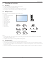
Package Contents
Please verify that you received the following items with your package content:
• LCD display
• Remote control with AAA batteries
• Power cord (1.8 m)
• RS232 cable (1.8 m)
• DP cable (1.8m)
• IR extender cable (1.5m)
• IR loop cable (1.8m)
Remote Control
and AAA Batteries
• RS232 loop cable (1.8m)
• Alignment plate: 3 pieces
• Washer: 4 pieces
• Screw: 4 pieces
• Spacer: 6 pieces
• Quick Start Guide
Power Cord
RS232 Cable
DP Cable
IR Extender Cable
Alignment Plate (3)
Spacer (6) Washer (4)
Screw (4)
Quick Start Guide
RS232 Loop Cable
IR Loop Cable
NOTES:
• For all other regions, apply a power cord that conforms to the AC voltage of the power socket and has been approved by and complies with the
safety regulations of the particular country.
• You might like to save the package box and packing material for shipping the display.
1.3.
Installation Notes
• Due to high power consumption, always use the plug exclusively designed for this product.
• The product should be installed on a flat surface to avoid tipping. The distance between the back of the product and the wall should be maintained
for proper ventilation. Avoid installing the product in the kitchen, bathroom or any other places with high humidity so as not to shorten the service life
of the electronic components.
• The product can normally operate only under 3000m in altitude. In installations at altitudes above 3000m, some abnormalities may be experienced.
1
Planar RA-Series
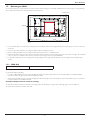
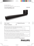
1.4.
IR remote sensor and power status indicator
1. For optimal IR remote control performance, pull down the retractable lens from the backside of the display. The LED power status light is also best
viewed when the lens is pulled down.
2. When tiled in video walls, the lens should be pushed up to optimize tiling.
3. You will hear a click when the lens is fully in position.
Push up to collapse the lens
Pull down to extend the lens
2
Planar RA-Series
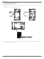
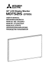
1.5.
Mounting on a Wall
To mount this display to a wall, you will have to obtain a standard wall-mounting kit (commercially available). We recommend using a mounting interface
that complies with TUV-GS and/or UL1678 standard in North America.
Protective Sheet
VESA Grid
Table
1. Lay a protective sheet on a table, which was wrapped around the display when it was packaged, beneath the screen surface so as not to scratch the
screen face.
2. Ensure you have all accessories for mounting this display (wall mount, ceiling mount etc).
3. Before mounting the display to the mounting kit, follow the instructions of 1.4 to collapse the lens.
4. Follow the instructions that come with the base mounting kit. Failure to follow correct mounting procedures could result in damage to the equipment
or injury to the user or installer. Product warranty does not cover damage caused by improper installation.
5. For the wall-mounting kit, use M6 mounting screws (having a length 10 mm longer than the thickness of the mounting bracket) and tighten them
securely.
1.5.1. VESA Grid
RA-Series
400(H) x 400(V) mm
Caution:
To prevent the display from falling:
• For wall or ceiling installation, we recommend installing the display with metal brackets which are commercially available. For detailed installation
instructions, refer to the guide received with the respective bracket.
• To lessen the probability of injury and damage resulting from fall of the display in case of earthquake or other natural disaster, be sure to consult the
bracket manufacturer for installation location.
Ventilation Requirements for enclosure locating
To allow heat to disperse, leave 25mm between surrounding objects and the display. For larger video walls, larger gaps around the display are
recommended and depend on the size of the wall.
3
Planar RA-Series
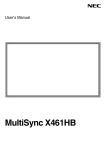
1.6.
Mounting in Portrait Position
This display can be installed in portrait position.
1.
Rotate 90 degrees counter clockwise from the back side of the display. The terminals will be on the right and top side of the user from the back of
the display.
2.
You can also refer to the arrow mark on the label on the back cover.
90
90
TM
Display
NOTE:
When installing the display on a wall, please consult a professional technician for proper installation. We accept no liability for installations not
performed by a professional technician.
4
Planar RA-Series
2.
Parts and Functions
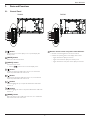
2.1.
Control Panel
RA4980:
2
4
6
8
1
RA5580:
1
2
3
4
9
5
6
7
8
[ ] button
9
Use this button to turn the display on or to put the display into
standby mode.
2
-- Lights off when the main power of the display is turned off
[INPUT] button
] button in the On-Screen-Display menu.
[ ] button
[ ] button
Decrease the adjustment while OSD menu is on, or decrease the
audio output level while OSD menu is off.
6
[ ] button
Move the highlight bar up to adjust the selected item while OSD
menu is on.
7
[ ] button
Move the highlight bar down to adjust the selected item while OSD
menu is on.
8
Remote control sensor and power status indicator
-- Lights amber when the display is in standby mode
Increase the adjustment while OSD menu is on, or increase the
audio output level while OSD menu is off.
5
9
7
-- Lights off when the display is turned on
Choose the input source.
4
5
• Indicates the operating status of the display without OPS:
[MUTE] button
• Used as [
3
• Receives command signals from the remote control.
Switch the audio mute ON/OFF.
3
1
[MENU] button
Return to previous menu while OSD menu is on, or to activate the
OSD menu when OSD menu is off.
5
Planar RA-Series
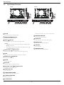
2.2.
Input/Output Terminals
RA4980:
RA5580:
22
20
2
4
1
1
3
22
21
20
19
17
13
6 8
5 7 9 10 11 12 14 15 16 18
2
AC IN
18 SPEAKER
MAIN POWER SWITCH
IR IN /
4
IR OUT
9
RS232C OUT
HDMI2 IN
HDMI video/audio input.
10 DVI
IN
11 DVI
OUT
DVI-D video input.
DVI, VGA, HDMI, or OPS video output.
12 DisplayPort
IN /
13
DisplayPort OUT
DisplayPort video input / output.
14 VGA
IN (D-Sub)
VGA video input.
15 COMPONENT VIDEO
Component YPbPr video source input.
16 COMPOSITE VIDEO
Video source input.
17 PC AUDIO
OUT
Audio output to external speakers.
LAN
HDMI1 IN /
OUT
22 SPEAKERS
LAN control function for remote control from a network.
8
20 AUDIO
For FW update.
RS232C network input / output for the loop-through function.
7
IN
21 USB(FW)
• To remotely control your A/V device via this display, refer to page
13 f���
or IR Pass Through connection.
6
19 AUDIO
Audio output to external AV device.
NOTES:
• This display’s remote control sensor will stop working if the jack
[IR IN] is connected.
RS232C IN /
SWITCH
Audio input from external AV device (RCA).
IR signal input / output for the loop-through function.
5
17
13
6 8
5 7 9 10 11 12 14 15 16 18
Internal speaker on/off switch.
Switch the main power on/off.
3
3
Audio input for VGA source (3.5mm stereo phone).
AC power input from the wall outlet.
2
4
1
IN
6
21
19
Planar RA-Series
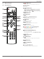
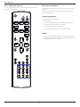
2.3.
Remote Control
1
[ ] POWER button
Turn the display on or to put the display into standby mode.
2.3.1. General functions
2
[PLAY] buttons
No function.
3
1
2
[
] HOME button
Access the OSD menu.
5
6
13
5
14
[
] LIST button
No function.
12
4
[ ] [ ] [ ] [ ] NAVIGATION buttons
Navigate through menus and choose items.
7
[
] button
Confirm an entry or selection.
8
6
[ ] ADJUST button
Access currently available picture and sound menus.
7
8
] SOURCE button
Choose input source. Press [ ] or [ ] button to choose from
HDMI 1, HDMI 2, DisplayPort, Card OPS, DVI-D,
] button to confirm and exit.
YPbPr, AV, or VGA. Press [
4
3
[
9
[
] MUTE button
Press to turn the mute function on/off.
15
10 [
][
][
][
] COLOR buttons
Red: Press to turn the tiling enable function on/off.
9
Green/Yellow/Blue: No function.
16
11 [Number/
ID SET/ ENTER] button
Enter text for network setting.
10
Press to set the display ID. Refer to 2.3.2. ID Remote Control
for more detail.
12 [
11
] FORMAT button
Change aspect ratio.
13 [
] BACK button
Return to the previous menu page or exit from the previous
function.
14 [
] INFO button
View info about the display.
15 [
] OPTIONS button
No function.
16 [
] [ ] VOLUME button
Adjust volume on internal or external audio sources.
7
Planar RA-Series
2.3.2. ID Remote Control
Entering/Leaving ID Mode
You can set the remote control ID when you want to use the remote
control on specific displays.
To enter ID mode: Press and hold the [ID ] button until the red LED
blinks twice
To leave ID mode: Press and hold the [NORMAL] button until the
green LED blinks twice
Programming ID Mode
To assign an ID to a remote control
1. Enter ID mode
2. Press and hold the [ID SET] button until the red LED turns on
3. Using the numeric keypad, enter the desired ID
4. Press the [ENTER] button to confirm ID
5. The red LED will blink twice when ID has been confirmed
NOTE:
• To cancel or stop programming an ID, press the [ID SET] button.
•
8
Programming of the remote will be automatically canceled if no
buttons are pressed for 10 seconds.
Planar RA-Series
2.3.3. Inserting the batteries in the remote control
The remote control is powered by two 1.5V AAA batteries.
To install or replace batteries:
1. Press and then slide the cover to open it.
2. Align the batteries according to the (+) and (–) indications inside the
battery compartment.
3. Replace the cover.
Caution:
The incorrect use of batteries can result in leaks or bursting. Be sure to follow these instructions:
• Place “AAA” batteries matching the (+) and (–) signs on each battery to the (+) and (–) signs of the battery compartment.
• Do not mix battery types.
• Do not combine new batteries with used ones. It causes shorter life or leakage of batteries.
• Remove the dead batteries immediately to prevent them from liquid leaking in the battery compartment. Don’t touch exposed battery acid, as it can
damage your skin.
NOTE:
If you do not intend to use the remote control for a long period, remove the batteries.
2.3.4. Handling the remote control
• Do not subject to strong shock.
• Do not allow water or other liquid to splash the remote control. If the remote control gets wet, wipe it dry immediately.
• Avoid exposure to heat and steam.
• Other than to install the batteries, do not open the remote control.
9
Planar RA-Series
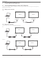
3.
Connecting External Equipment
3.1.
Connecting Multiple Displays in a Daisy-chain Configuration
The Planar RA-Series displays are designed to be installed in a daisy-chain configuration for video walls. Note: For larger video wall configurations, a
distribution amp is recommended.
3.1.1. Display control connection
RS232
DISPLAY 1
DISPLAY 2
PC
[RS-232C]
[RS-232C IN]
[RS-232C OUT]
[RS-232C IN]
3.1.2. Digital video connection
There are a variety of ways to daisy chain digital signals on the RA-Series.
DVI
DISPLAY 1
DISPLAY 2
PC
[DVI]
[DVI IN]
[DVI OUT]
[DVI IN]
DisplayPort
DISPLAY 1
DISPLAY 2
PC
[DP]
[DP IN]
[DP OUT]
10
[DP IN]
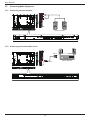
Planar RA-Series
HDMI
DISPLAY 1
DISPLAY 2
[HDMI]
[DVI IN]
[DVI OUT]
[DVI IN]
OPS
OPS
DISPLAY 1
DISPLAY 2
[DVI OUT]
[DVI IN]
3.1.3. Analog video connection
VGA
DISPLAY 1
DISPLAY 2
PC
[VGA]
[VGA IN]
[DVI/VGA OUT]
11
[VGA IN]
Planar RA-Series
3.2.
Connecting Audio Equipment
3.2.1. Connecting external speakers
External speakers
3.2.2. Connecting an external audio device
Audio In
[AUDIO OUT]
12
Stereo Amplifier
Planar RA-Series
3.3.
IR connection
External
IR Receiver
DISPLAY 1
[IR IN]
DISPLAY 2
[IR OUT]
NOTE:
This display’s remote control sensor will stop working if the [IR IN] is connected.
3.4.
IR Pass-through Connection
[IR IN]
DVD / VCR / VCD
[IR OUT]
[IR IN]
(DVD / VCR / VCD)
Remote Control
(DS474PMN)
13
Planar RA-Series
4.
Operation
5.
Using the remote control:
NOTE: The control button described in this section is mainly on the
remote control unless specified otherwise.
4.1.
Watch the Connected Video Source
1. Press [
] SOURCE button.
2. Press [ ] or [ ] button to choose a device, then press [
button.
4.2.
Change your settings
]
Change Aspect Ratio
You can change the aspect ratio to suit the video source. Each video
source has its available aspect ratios..
The aspect ratios depend on the video source:
1. Press [
] FORMAT button.
1. Press [
2. Press [ ] or [ ] button to choose an aspect ratio, then press [
] button.
Options: Auto, Letterbox, Full Screen, Native, 4:3
4.3.
3. Press [ ] [ ] [ ] or [ ] button to choose its menu item or to
adjust its value. Press [
] button to confirm.
Choose your Preferred Picture Settings
1. While the display is playing a video source, press the [
button.
] ADJUST
4. Press [
5. Press [
2. Press [ ] or [ ] button to choose Picture style , then press
[
] button.
3. Options: General, Vivid, Natural, Standard, Movie, Photo, Energy
Saving
4.4.
] HOME button to display the OSD menu.
2. Press [ ] [ ] [ ] or [ ] button to choose Picture, Sound,
Tiling, General Settings or Network settings. Press
[
] button to enter.
] BACK button to go back to the previous menu layer.
] HOME button to exit the OSD menu.
Using the display’s control buttons
Choose your Preferred Sound Settings
1. While the display is playing a video source, press [
button.
] ADJUST
2. Press [ ] or [ ] button to choose Sound style , then press
[
] button.
Options: General, Original, Movie, Music, Game, News.
4.5.
Installing OPS Modules
The Planar RA-Series displays are equipped with an expansion slot that
supports the Intel® Open-Pluggable Specification (OPS). The slot will
support OPS devices such as PC’s, SDI modules, HDBaseT receivers,
etc. To install an OPS device, remove the protective cover on the display
and slide the device firmly into position. When installed, the OPS device
will be connected internally to the display. No external video or power
cables are required.
14
1. Press [
] button to display the OSD menu.
2. Press [ ] [
its value.
] [ ] or [ ] button to choose menu item or adjust
3. Press [
submenu.
] button to confirm menu selection and enter its
4. Press [
] button to exit the OSD menu.
Planar RA-Series
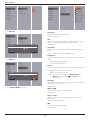
5.1.
Settings
• {Color Temp}: Change the color balance.
Options: 10000K, 9300K, 6500K, 3200K, Custom
• {Custom Color Temp}: Customize color balance setting. Only
available if {Color Temp} {Custom} is chosen. ·
5.1.1. Picture
Picture
Picture Style
R-Gain
Sound
Restore Style
Options: 0 - 255
Tiling
Backlight
G-Gain
General settings
Contrast
Network settings
Brightness
Options: 0 - 255
B-Gain
Hue
um
ne
Options: 0 - 255
Color
R-Offset
Sharpness
Options: 0 - 255
Noise Reduction
G-Offset
Advanced
Overscan
Options: 0 - 255
Color Space
B-Offset
Options: 0 - 255
Format
• {Advanced Sharpness}: Enable superior sharpness, especially on
lines and contours in the picture.
Picture Style
Options: Off, On
Choose a predefined picture setting.
• {Dynamic Contrast}: Dynamically enhance the details in the
dark, medium and light areas of the picture.
Options: General, Vivid, Natural, Standard, Movie, Photo, and Energy
Saving
Options: Off, Low, Medium, High
Note: YUV sources only.
• {Color Enhancement}: Dynamically enhance the vividness and
details of colors.
Restore Style
Restore the picture setting to default values.
Options: Off, Low, Medium, High
• {Dynamic Backlight}: Choose a backlight level which optimizes
dynamic power consumption and picture contrast.
Backlight
Adjust the intensity of the display’s backlight.
• Options: Off, Standard, Best Power, Best Picture.
Options: 0-100.
Overscan
Contrast
Enables or disables the overscan function.
Adjust video contrast.
Options: Off, On
Options: 0-100
Note: YUV sources only
Brightness
Color Space
Adjust screen brightness.
Select the color space of the source signal.
Options: 0-100
Options: Auto, RGB-Video, RGB-PC, YUV
Hue
Format
• {Aspect Ratio}: Change the picture format.
Adjust screen hue.
Options: -50 - +50
Options: Auto, Letterbox, Full Screen, Native, 4:3
Color
• {Picture Shift}:
Adjust the color saturation of the picture.
Adjust position of image.
Options: 0-100
Sharpness
Adjusts the definition of the picture.
Options: 0-20
Note: YUV sources only.
Noise Reduction
Choose the amount of noise reduction for the picture.
Options: Off, Low, Medium, High
Note: YUV sources only
Advanced
• {Gamma}: Adjust the non-linear setting for picture luminance
and contrast.
Options: 1.8, 1.9, 2.0, 2.1, 2.2, 2.3, 2.4, 2.5
15
Planar RA-Series
5.1.2. Sound
5.1.3. Tiling
Picture
Sound Style
Sound
Restore Style
Tiling
Bass
General settings
Treble
Network settings
Balance
Surround Mode
Picture
Enable
Sound
H Monitors
Tiling
V Monitors
General settings
Position
Network settings
Frame Comp
Hor Frame Comp
Audio Out
Vert Frame Comp
Advanced
Sound Style
Enable
Access predefined sound settings.
Enable video wall scaling
Options: General, Original, Movie, Music, Game, News
Options: Off, On
Restore Style
H Monitors
Restore the sound setting to default values.
Adjust displays on the horizontal side.
Bass
Options: 1 - 10
Adjust to increase or decrease lower-pitched sounds.
V Monitors
Options: -8 - +8
Adjust displays on the vertical side.
Treble
Options: 1 - 10
Adjust to increase or decrease higher-pitched sounds.
Position
Options: -8 - +8
Assign the position of the display in the video wall configuration
Balance
Options: 1 – 100
Adjust to emphasize left or right audio output balance.
Example: 2 x 2 screen matrix (4 displays)
H monitors = 2 displays
V monitors = 2 displays
Options: -8 - +8
Surround Mode
H monitors
Enhance your audio experience.
Options: Off, On
Audio Out
V monitors
Adjust audio output volume.For line out audio sources only.
Options: 0 - 60
Advanced
• {Auto Volume Leveling}: Enable the reduction of sudden volume
changes.
Options : Off, On
• {Internal Speakers}: Turn on or off the internal speakers.
1
2
3
4
Position
Example: 5 x 5 screen matrix (25 displays)
H monitors = 5 displays
V monitors = 5 displays
Options : Off, On
• {Clear Sound}: Enhance sound quality.
Options : Off, On
V monitors
H monitors
16
1
6
11
2
7
12
3
8
13
4
9
14
5
10
15
16
21
17
22
18
23
19
24
20
25
Position
Planar RA-Series
Frame Comp
Eco Mode
Choose to turn the frame compensation function on or off. If selected
{On}, the display will adjust the image to compensate for the width of
the display bezels in order to accurately display the image.
Select standby power consumption setting.
Options: Normal, Low power standby
Note: For the lowest standby power consumption, select Low power
standby. When the Eco mode is set to Low power standby, the display
cannot wake from sleep. When the Eco mode is set to Normal,
the display can wake from sleep. See Auto Search Setting for more
information on how to wake the display.
On}
Auto Search
Automatically detects available input sources when “On”. If “Backup
Source” is selected, assigned sources in designated sequential order will
be searched. When “Off ” the display will automatically detect the last
input.
Options: Off, On, Backup Source (Select up to 7)
Note: When set to “On”, the last input will wake the display. When
set to “Off ”, the last input will wake the display. When set to “Off ”, a
RS-232 command can wake the display using any input. When set to
“Backup source”, any active backup source (in sequential order) will
wake the display. Note that Eco Mode needs to be set to “Normal” for
the display to wake up.
{Off}
Clock
Set the current date (DD-MM-YYYY) and time
Scheduling
This function allows you to program up to 7 different scheduled time
intervals for this display to activate.
NOTES:
• Set up current date and time in the {Clock} menu before setting up
a schedule.
• After changing the date and time in the {Clock} menu, the schedule
may need to be re-entered.
Hor and Vert Frame Compensation
Provides variable adjustment horizontally or vertically for more precise
video wall frame compensation.
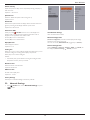
5.1.4. General settings
Picture
Monitor ID
Sound
Eco Mode
Tiling
Auto Search
General settings
Clock
Network settings
Scheduling
Picture
Monitor ID
Sound
Eco Mode
Tiling
Auto Search
General settings
Clock
Network settings
Scheduling
Sleep Timer
CEC
Auto Adjust
Keypad Lock
IR Lock
Pixel Shift
Wake on LAN
Sleep Timer
CEC
Auto Adjust
1. Up to 7 schedules can be programmed. To activate a schedule,
select Enable and choose On.
Keypad Lock
IR Lock
Pixel Shift
Wake on LAN
Monitor ID
Adjust the ID number for controlling the display via the RS232C
connection. Each display must have a unique ID number when multiple
sets of this display are connected. Monitor ID number range is between
1 to 255. The default setting is 1.
17
Planar RA-Series
Schedule 1
Enable
Off
Schedule 1
Enable
No Repeat
Schedule 2
On Time
On
Schedule 2
On Time
Every Sunday
Schedule 3
Off Time
Schedule 3
Off Time
Every Monday
Schedule 4
Repeat Modes
Schedule 4
Repeat Modes
Every Tuesday
Schedule 5
Schedule 5
Every Wednesday
Schedule 6
Schedule 6
Every Thursday
Schedule 7
Schedule 7
Every Friday
Every Saturday
2. Set On time.
Sleep Timer
Switch off this display after a specified time.
Schedule 1
Enable
Schedule 2
On Time
Schedule 3
Off Time
Schedule 4
Repeat Modes
Options: 0-240 seconds
CEC
Connect and control your HDMI-CEC compliant devices through the
HDMI port of this display using the same remote control.
Schedule 5
On6 Time
Schedule
Options: Off, On
Schedule 7
Auto Adjust
00 : 00
Cancel
Use this function to automatically optimize the display of VGA input
image.
Done
NOTE:
This item is functional for VGA input only.
Keypad Lock
Choose to enable or disable the keypad function on the backside of the
display.
3. Set Off Time.
• Unlock: Enable the keypad function.
Schedule 1
Enable
• Lock: Lock the keypad function.
Schedule 2
On Time
Schedule 3
Off Time
IR Lock
Schedule 4
Repeat Modes
Choose to enable or disable the button function of the remote control.
• {Unlock}: Enable the IR Remote function.
Schedule 5
ScheduleOff
6 Time
Schedule 7
• {Lock}: Lock all IR Remote function.
NOTE:
14 : 00
Cancel
Done
To disable the lock function from Keypad Lock or IR lock item, press buttons [ ] and 1 9 9 8 on the
remote control.
Pixel Shift
Automatically moves the screen image every 30 minutes to protect the
display from “burn-in” symptoms.
Options: Off, On
4. Go to Repeat Modes and choose.
Wake on LAN
Wake the display through a network connection.
Options: Off, On
Switch on State
Choose the display status used for the next time you connect the
power cord.
Options: On, Standby, Last Status
LED
Enables or disables the indicator light
Options: Off, On
18
Planar RA-Series
Switch on Delay
Adjusts the power-on delay time for sequential powering of displays by
their ID number.
Options: 0 – 60 seconds
Splash Screen
Picture
View Network Settings
Network Type
Sound
Network Configuration
Network Mode
Tiling
Static IP Configuration
IP Address
General settings
Netmask
Network Settings
Ethernet MAC Address
Enables or disables the splash screen during start up
Gateway
Options: Off, On
DNS 1
Auto Power
DNS 2
Select the time period before the display will turn off when there is no
signal. By choosing off, the display will never power down.
Options: Off, 1-60 seconds
Information OSD
When you press [ ] POWER button to turn on the display from
standby mode or change the input signal, the information OSD is
displayed on the upper left corner of the screen.
View Network Settings
View connected network status.
Network Configuration
Choose {On} to turn on this function.
{Network configuration}: Choose how this display should assign
addresses to the network resources. The user can choose {DHCP & Auto IP} (suggested) or {Static IP}.
Choose {Off} to turn off this function.
DisplayPort Ver.:
Select DisplayPort version.
Static IP Configuration
Options: 1.1a, 1.2.
Define {IP Address}, {Netmask}, {Gateway}, {DNS1}, and {DNS2} for
this display. If {Network settings} {Static IP} is chosen.
Cooling Fan
Select {On} to turn on the cooling fan all the time. Select {Auto} to turn
on/off the cooling fan according to the display’s temperature.
Select {Off} to turn off the cooling fan.
NOTES:
• The default {Auto} option will start running the cooling fan if the
temperature of 60°C (140°F) is reached.
RS-232 Control
Select the RS-232 control location
Options: External, OPS
OSD Time Out
Set OSD menu display time
Options: 10 – 60 sec.
Factory Settings
Reset all your customized settings to the factory defaults.
5.2.
Network Settings
1. Press [ ] HOME button, choose Network Settings and press
[
] button.
19
Planar RA-Series
6.
Input Mode
VGA Resolution:
Standard
Resolution
Active Resolution
H Pixels
V Lines
VGA
640
480
WVGA
720
400
SVGA
800
600
XGA
1024
768
WXGA
WXGA
SXGA
WXGA
WXGA
UXGA
HD1080
1280
1280
1280
1360
1366
1600
1920
768
800
1024
768
768
1200
1080
Refresh Rate
Pixel Rate
Aspect Ratio
Stand for Mode
60 Hz
72 Hz
75 Hz
70 Hz
60 Hz
75 Hz
60 Hz
75 Hz
60 Hz
60 Hz
60 Hz
60 Hz
60 Hz
60 Hz
60 Hz
25.175 MHz
31.5 MHz
31.5 MHz
33.75 MHz
40 MHz
49.5 MHz
65 MHz
78.75 MHz
79.5 MHz
79.5 MHz
108 MHz
85.5 MHz
85.5 MHz
162 MHz
148.5 MHz
4:3
Video Graphic Array
16:9
Wide Video Graphic Array
4:3
Super VGA
4:3
Extended Graphic Array
5:3
16:10
5:4
16:9
16:9
4:3
16:9
Wide XGA
Wide XGA
Super XGA
Wide XGA
Wide XGA
Ultra XGA
HD1080
Refresh Rate
Pixel Rate
Aspect Ratio
Stand for Mode
29.97 Hz
59.94 Hz
25 Hz
50 Hz
13.5 MHz
27 MHz
13.5 MHz
27 MHz
4:3
Modified NTSC Standard
4:3
Modified PAL Standard
Refresh Rate
Pixel Rate
Aspect Ratio
Stand for Mode
74.25 MHz
16:9
Normally DVB Mode
74.25 MHz
16:9
Normally ATSC Mode
148.5 MHz
16:9
Normally ATSC Mode
SDTV Resolution:
Standard
Resolution
480i
480p
576i
576p
Active Resolution
H Pixels
V Lines
720
480
720
480
HDTV Resolution:
Standard
Resolution
Active Resolution
H Pixels
V Lines
720p
1280
720
1080i
1920
1080
1080p
1920
1080
50 Hz
60 Hz
25 Hz
30 Hz
50 Hz
60 Hz
UHDTV Resolution:
Active Resolution
H Pixels
V Lines
UHDTV Resolution
3840
Refresh Rate
Pixel Rate
Aspect Ratio
Stand for Mode
30
297MHz
16:9
Video wall
application.
2160
Note: UHD resolution is supported only on video wall arrays. Each individual LCD display supports a max resolution of 1080p.
20
Planar RA-Series
7.
Troubleshooting
Symptom
Possible Cause
Remedy
No picture is displayed
1. The power cord is disconnected.
1. Plug in the power cord.
2. The main power switch on the back of the
display is not switched on.
2. Make sure the power switch is switched on.
3. The selected input has no connection.
3. Connect a signal connection to the display.
4. The display is in standby mode.
Interference displayed on the display or audible
noise is heard
Caused by surrounding electrical appliances or
fluorescent lights.
Move the display to another location to see is the
interference is reduced.
Color is abnormal
The signal cable is not connected properly.
Make sure that the signal cable is attached firmly
to the back of the display.
Picture is distorted with abnormal patterns
1. The signal cable is not connected properly.
1. Make sure that the signal cable is attached
firmly.
2. The input signal is beyond the capabilities of
the display.
Display image doesn’t fill up the full size of the
screen
1. The zoom mode is not set correctly.
2. Scan Mode may be set incorrectly to
underscan.
2. Check the video signal source to see if it
is beyond the range of the display. Please
verify its specifications with this display’s
specification section.
Use the Zoom mode or Custom zoom function
in the Screen menu to fine tune display geometry
and time frequency parameter.
3. If the image exceeds the screen size, Scan
Mode may need to be set to Underscan.
Can hear sound, but no picture
Improperly connected source signal cable.
Make sure that both video inputs and sound
inputs are correctly connected.
Can see picture but no sound is heard
1. Improperly connected source signal cable.
1. Make sure that both video inputs and sound
inputs are correctly connected.
2. Volume is turned all the way down.
3. {Mute} is turned on.
4. No external speaker connected.
2. Press [
] or [
] button to hear sound.
3. Switch MUTE off by using the [
] button.
4. Connect external speakers and adjust the
volume to a suitable level.
Some picture elements do not light up
Some pixels of the display may not turn on.
This display is manufactured using an extremely
high level of precision technology: however,
sometimes some pixels of the display may not
display. This is not a malfunction.
After-Images can still be seen on the display
after the display is powered off. (Examples
of still pictures include logos, video games,
computer images, and images displayed in 4:3
normal mode)
A still picture is displayed for an over extended
period of time
Do not allow a still image to be displayed for
an extended period of time as this can cause a
permanent after-image to remain on the display.
21
Planar RA-Series
8.
Technical Specifications
8.1.
RA4980
Display:
Item
Specifications
Screen Size (Active Area)
48.50” (123.2 cm) LCD Aspect Ratio
16:9
Number of pixels
1920 (H) x 1080 (V)
Pixel pitch
0.55926 (H) x 0.55926 (V) [mm]
Displayable colors
10bits(D),1.06 Billion colors
Brightness (typical)
700 cd/m2
Contrast ratio (typical)
1300:1
Viewing angle
178 degrees
In/Out Terminals:
Item
Speaker Output
Specifications
Internal Speakers
10W (L) + 10W (R) [RMS]/8Ω
External Speakers
1 Way 1 Speaker System
82 dB/W/M/160 Hz ~ 13 KHz
Audio Output
Phone Jack x 1
0.5V [rms] (Normal) / 2 Channel (L+R)
Audio Input
RCA Jack x 2
0.5V [rms] (Normal) / 2 Channel (L+R)
3.5 mm Stereo x 1
RS232C
2.5mm Phone jack x 2
RS232C in/RS232C out
RJ-45
RJ-45 Jack x 1 (8 pin)
10/100 LAN Port
HDMI Input
HDMI Jack x 2 (Type A) (18 pin)
Digital RGB: TMDS (Video + Audio)
MAX:
Video - 720p, 1080p, 1920 x 1080/60 Hz (WUXGA)
Audio - 48 KHz/ 2 Channel (L+R)
Supports LPCM only
DVI-D Input
DVI-D jack
Digital RGB: TMDS (Video)
VGA Input
D-Sub Jack x 1 (15 pin)
Analog RGB: 0.7V [p-p] (75Ω), H/CS/V: TTL (2.2kΩ), SOG: 1V [p-p] (75Ω)
MAX: 720p, 1080p, 1920 x 1080/60 Hz (WUXGA)
DVI-I (DVI-D & VGA)
Output
DVI-I Jack x 1 (29 pin)
Digital RGB: TMDS (Video)
Component Input
BNC Jack x 3
Video Input
BNC x 1 (Share with
Component_Y)
Composite 1V [p-p] (75Ω)
Displayport in/out
Displayport Jack x 2
(20 pin)
Digital RGB: TMDS (Video + Audio)
Analog RGB: 0.7V [p-p] (75Ω), H/CS/V: TTL (2.2kΩ), SOG: 1V [p-p] (75Ω)
MAX: 720p, 1080p, 1920 x 1080/60 Hz (WUXGA)
Y: 1V [p-p] (75Ω), Pb: 0.7V [p-p] (75Ω), Pr: 0.7V [p-p] (75Ω)
MAX: 480i, 576i, 480p, 576p, 720p, 1080i, 1080p
MAX:
Video - 720p, 1080p, 1920 x 1080/60 Hz (WUXGA) Audio - 48 KHz/ 2 Channel (L+R)
Supports LPCM only
22
Planar RA-Series
General:
Item
Specifications
Power Input
100 - 240V ~, 50 - 60Hz
Power Consumption (Max)
240 W
Power Consumption (typ.)
120 W
Power Consumption (Standby & Off)
<0.5W (RS232 in active)
Dimensions [W x H x D]
1092.3 x 622.5 x 71.1(@Handle)/56.8(@Wall Mount)mm
Weight
19.0 Kg
Gross Weight
25.3 Kg
Environmental Condition:
Item
Temperature
Humidity
Altitude
Specifications
Operational
0 ~ 40°C
Storage
-20 ~ 60°C
Operational
20 ~ 80% RH (No condensation)
Storage
5 ~ 95% RH (No condensation)
Operational
0 ~ 3,000 m
Storage / Shipment
0 ~ 9,000 m
Internal Speaker:
Item
Specifications
Type
1 Way 1 Speaker
Input
10 W (RMS)
Impedance
8Ω
Output Sound Pressure
82 dB/W/M
Frequency Response
160 Hz ~ 13 KHz
23
Planar RA-Series
8.2.
RA5580
Display:
Item
Specifications
Screen Size (Active Area)
54.64” (138.78 cm) LCD Aspect Ratio
16:9
Number of pixels
1920 (H) x 1080 (V)
Pixel pitch
0.630 (H) x 0.630 (V) [mm]
Displayable colors
10bits(D),1.06 Billion colors
Brightness (typical)
700 cd/m2
Contrast ratio (typical)
1300:1
Viewing angle
178 degrees
In/Out Terminals:
Item
Speaker Output
Specifications
Internal Speakers
10W (L) + 10W (R) [RMS]/8Ω
External Speakers
1 Way 1 Speaker System
82 dB/W/M/160 Hz ~ 13 KHz
Audio Output
Phone Jack x 1
0.5V [rms] (Normal) / 2 Channel (L+R)
Audio Input
RCA Jack x 2
0.5V [rms] (Normal) / 2 Channel (L+R)
3.5 mm Stereo x 1
RS232C
2.5mm Phone jack x 2
RS232C in/RS232C out
RJ-45
RJ-45 Jack x 1 (8 pin)
10/100 LAN Port
HDMI Input
HDMI Jack x 2 (Type A) (18 pin)
Digital RGB: TMDS (Video + Audio)
MAX:
Video - 720p, 1080p, 1920 x 1080/60 Hz (WUXGA)
Audio - 48 KHz/ 2 Channel (L+R)
Supports LPCM only
DVI-D Input
DVI-D jack
Digital RGB: TMDS (Video)
VGA Input
D-Sub Jack x 1 (15 pin)
Analog RGB: 0.7V [p-p] (75Ω), H/CS/V: TTL (2.2kΩ), SOG: 1V [p-p] (75Ω)
MAX: 720p, 1080p, 1920 x 1080/60 Hz (WUXGA)
DVI-I (DVI-D & VGA)
Output
DVI-I Jack x 1 (29 pin)
Digital RGB: TMDS (Video)
Analog RGB: 0.7V [p-p] (75Ω), H/CS/V: TTL (2.2kΩ), SOG: 1V [p-p] (75Ω)
MAX: 720p, 1080p, 1920 x 1080/60 Hz (WUXGA)
Component Input
BNC Jack x 3
Y: 1V [p-p] (75Ω), Pb: 0.7V [p-p] (75Ω), Pr: 0.7V [p-p] (75Ω)
MAX: 480i, 576i, 480p, 576p, 720p, 1080i, 1080p
Video Input
BNC x 1 (Share with
Component_Y)
Composite 1V [p-p] (75Ω)
Displayport in/out
Displayport Jack x 2
(20 pin)
Digital RGB: TMDS (Video + Audio)
MAX:
Video - 720p, 1080p, 1920 x 1080/60 Hz (WUXGA) Audio - 48 KHz/ 2 Channel (L+R)
Supports LPCM only
24
Planar RA-Series
General:
Item
Specifications
Power Input
100 - 240V ~, 50 - 60Hz,
Power Consumption (Max)
265 W
Power Consumption (typ.)
145 W
Power Consumption (Standby & Off)
<0.5W (RS232 in active)
Dimensions [W x H x D]
1228.1 x 698.9 x 71.1(@Handle)/56.8(@Wall Mount)mm
Weight
24.7 Kg
Gross Weight
31.4 Kg
Environmental Condition:
Item
Temperature
Humidity
Altitude
Specifications
Operational
0 ~ 40°C
Storage
-20 ~ 60°C
Operational
20 ~ 80% RH (No condensation)
Storage
5 ~ 95% RH (No condensation)
Operational
0 ~ 3,000 m
Storage / Shipment
0 ~ 9,000 m
Internal Speaker:
Item
Specifications
Type
1 Way 1 Speaker
Input
10 W (RMS)
Impedance
8Ω
Output Sound Pressure
82 dB/W/M
Frequency Response
160 Hz ~ 13 KHz
25
Planar RA-Series
PLANAR SUPPORT
Technical Support
Visit Planar at http://www.planar.com/support for user manuals and warranty information.
To speak with Planar Customer Support please have you model and serial number available and dial:
Planar Support
Tel: 1-866-PLANAR1 (866-752-6271) or +1 503-748-5799 outside the US.
Hours: 24 hours a day, 7 days a week.
Toll or long distance charges may apply.
26
Customer Service
24x7 Online Technical Support :http://www.planar.com/support
1195 NW Compton Drive
Beaverton,OR 97006-1992
Tel:1-866-PLANAR1(866-752-6271),or +1 503-748-5799 outside the United States.
2015 Planar Systems,Inc.
Planar is a registered trademark of Planar Systems,Inc. Other brands and names are
the property of their respective owners. Technical information in this document is
subject to change without notice.
PN: 020-1281-00