1
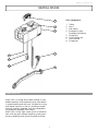
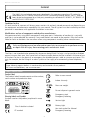
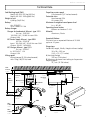
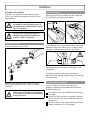
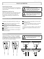
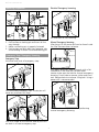
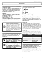
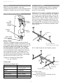
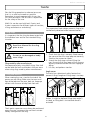
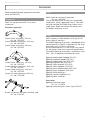
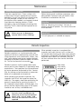
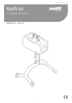
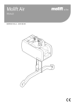
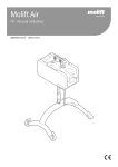
Molift Air
EN - User manual
BM16101 Rev. E 2015-01-15
Molift Air / www.etac.com
English Manual
Content
Important
Molift Air 205/300.....................................2
Hoist components...................................2
About Molift Air......................................2
General......................................................3
Declaration of conformity.........................3
Conditions for Use...................................3
Warranty.................................................3
Product identification...............................3
Technical Data............................................4
Installation.................................................5
Trolley installation....................................5
Lifter installation......................................5
Checklist after installation........................5
How to use Molift Air.................................6
Before use / Daily check...........................6
Hand control...........................................6
Mounting Suspension..............................7
Emergency Stop / Emergency lowering.....7
Electronics..................................................8
Transport and Operating Conditions.........8
Batteries..................................................8
Battery and Service indicator....................8
Service Scope..........................................8
Charging.................................................9
Charging through Hand Control...............9
IRC - In Rail Charging...............................9
Transfer....................................................10
Using Slings...........................................10
Lifting and lowering...............................10
Accessories.............................................. 11
Suspensions........................................... 11
Slings.................................................... 11
Scale..................................................... 11
Maintenance............................................ 12
Cleaning and disinfeciton....................... 12
Reconditioning...................................... 12
Recycling............................................... 12
Spare Parts............................................ 12
Periodic Inspection................................... 12
Pericodic Inspection Scope..................... 12
Troubleshooting....................................... 13
This User Manual contains important safety
instructions and information regarding the use of
the lifter and accessories.
In this manual the user is the person being lifted.
The assistant is the person operating the lifter.
Warning!
This symbol indicates important
information related to safety.
Follow these instructions carefully.
Read User Manual before use!
It is important to fully understand
the content of the user manual
before attempting to use the
equipment.
Visit www.etac.com for download of documentation to ensure you have the latest version.
1
Molift Air / www.etac.com
Molift Air 205/300
1
2
3
Hoist components:
1.
2.
3.
4.
5.
6.
7.
8.
7
4
5
6
8
About Molift Air
Molift AIR is a strong and smooth ceiling lift that
enables patients and residences to be transferred
in a comfortable and safe way. Suitable for sitting
and lateral transfers as well as standing and gait
training situations together with the comprehensive accessory program from Molift.
Molift AIR is a very light motor which in combination with the quick release coupling system gives
an easy handling when mounting and servicing
2
Trolley
Hoist
Side covers
Emergency stop/
Emergency lowering
Lifting belt
Quick release pin
Hand control
Suspension
Molift Air / www.etac.com
General
Declaration of conformity
The Molift Air and related accessories described in this operator manual are CE marked in
accordance with EU Council Directive 93/42/EEC concerning medical devices, class 1, and has
been tested and approved by a third party according to standards IEC 60601-1, IEC 60601-1-2
and NS-EN ISO 10535:2006.
Conditions for Use
Lift and transfer of a person will always pose a certain risk and only trained personnel are allowed to use
the equipment and accessories covered by this user manual. The rail system must be installed by certified
personnel in accordance with applicable installation instructions.
Modifications and use of components made by other manufacturers.
We recommend only using Molift components and spare parts. Declaration of conformity is not valid
and Etac is not responsible for warranty if any modifications are made to the product. Etac shall not be
liable for faults or accidents that can occur when using components made by other manufacturers.
Only certified personnel are allowed to open hoist or accessories to perform service
or repair. Risk of injury from rotating parts and electric shock.
The lifter is not intended to be operated by the person being lifted. If a hoist is to be used by a disabled
person living on their own, then some form of communication device shall be installed in the area of use
of the hoist so that in the event of an emergency the disabled person is able to summon assistance. This
may, for example, be the fitting of an alarm system or the supply of a conveniently placed telephone,
etc.
Warranty
2-year warranty against defects in workmanship and materials of our products.
For Terms and conditions, see www.etac.com
Product identification
Product label
Refer to user manual
The Product labels barcode contain article number,
serial number and production date.
Indoor Use only
255
560
Max user weight
Do not dispose in general waste
Warning labels and Symbols
Emergency stop/
Emergency lowering
Symbols used on the product, explained in more
detail:
Service Light
Battery Light
Class II double insulated
Hex tool symbol for Manual
Emergency lowering
CE marked
3
Molift Air / www.etac.com
Technical Data
Safe Working Load (SWL)
Propulsion motor speed
0,2m/second (7,87 inches/second)
Hand control IP24
Lift motor IP24
Molift AIR 205: 205 kg (450 lbs)
Molift AIR 300: 300kg (660 lbs)
Protection class
Weight of unit
8,46 kg (18,65 lbs)
Art: 2510023
26.4 V NiMH 2.2 Ah
Battery:
Maximum A-weighted sound power level
LWA = 63 dB
Battery charger:
Charger for handcontrol, Mascot - type 2215
Art. no.: 1240100
100-240 V AC, 50-60 Hz max 0.9A
Output 0.9A
Buttons on handset: 3.4 N
Aluminum, Plastic
Material:
Expected Lifetime:
IRC Power Supply, Mascot - type 9920
Art. no.: 2510119
Input: 100-240 VAC, 50-60 Hz max 0.9A
Output: 24VDC 1.6A/40W
IRC Charger, Mascot - type 2515
Art. no.: 2510147
In: 20-30VDC 1.3A
Output 0.5A
The hoist has an expected lifetime of 30 000
cycles or 10 years.
Dimensions:
L x W x H (Length, Width, Height without trolley)
36 x 19 x 19,5 cm
(14,2 x 7,5 x 7,7 inches)
A (Hoisting Range)
300 cm (118 Inches)
B (Minimum distance from ceiling to Suspension
coupling point)
32,7 cm (12.7⁄8 Inches)
Lifting speed
Operating forces button
60mm/second (2,36 inches/second)
with 75kg (165,35 lbs) load
Min.
62mm
2,44”
F Min.
385mm
15,15”
F Min.
475mm
18,7”
C 29,5mm
1,16” /
72,5mm
2,85”
B Min.
327mm
12,87”
D 245,5mm
9,66”
A 3000mm
118,11”
W 190mm
7,48”
H 195mm
7,67”
L 360mm
14,17”
CSP
Min.
120mm
4,72”
E 10mm
0,39”
Min.
210mm
8,26”
Min. 300mm
11,81”
4
Molift Air / www.etac.com
Installation
Assembly and installation
Lifter installation
The hoist is marked with Safe Working Load
(SWL), this should not exceed rail systems max
load capacity.
Mounting of Lifter on trolley. No tools required.
The lifter has two connection points.
The rail system can only be
installed by certified personnel in
accordance with applicable installation instructions.
Do not start using hoist before
completing control according to
checklist after installation.
Trolley installation
Connect one point first. Push button all the way
in, and place lifter in connection point on trolley.
Release button and make sure it is clearly showing green before connecting the next point.
Mounting trolley in rail system
Make sure both connection point buttons
completely return and clearly show green after
installation.
Emergency lowering cord and tube can be
adjusted to the correct length (height) by cutting
tube and cord.
Checklist after installation
Remove End stop and insert Trolley into rail.
Mount end stop, and make sure it is securely
fastened
Use this checklist to verify that the hoist is
properly installed and can operate correctly an
d safely before use.
Make sure end stops are mounted
in all ends of the Rail system before
using the hoist!
End stops on rail are installed after mounting
of trolley
Make sure that the hoist is properly fastened
to the rail and that the lift does not have any
loose parts.
Perform one lift with normal load (60-80 kg)
Make sure battery is fully charged.
5
Molift Air / www.etac.com
How to use Molift Air
General Safety Precautions
Safe Working Load
Only use accessories and slings that are adjusted
to fit the user, type of disability, size, weight and
type of transfer.
If maximum load (SWL) differs
between hoist suspension and body
support unit, then the lowest maximum load shall always be used
Working pause ratio/Duty Cycle.
Molift Air should not be run constantly for more
than 2 minutes (with maximum load), and rest
for minimum 18 minutes. Duty Cycle 10%.
(Intermittence according to standard ISO-EN
10535)
Molift lifters shall only be used to lift
persons. Never use the lifter to lift or
move objects of any kind.
Before use / Daily check
Inspection to be performed daily or before use:
Inspect lifter and rail system has no visible
damage, defects or deformations
Make sure suspension connection and all
detachable parts are properly connected and
secured
Test emergency stop button and emergency
lowering
Make sure battery indicator or service light is
not illuminated
Make sure lifting strap does not have visible
damage or frays.
Test run lifters operation functions and make
sure lifter does not make any abnormal
sounds
If there are any faults or defects, the lift needs to
be taken out of operation and marked ”out of
order”
Hand control
The Hand control has 2 buttons for lifting and
lowering, or 4 buttons if the hoist is equipped
with propulsion. The Hand control has an indicator light that will illuminate when battery level is
low and the lifter requires charging
Do not pull Hand control to move
the hoist along the rail
6
Molift Air / www.etac.com
Mounting Suspension
Electrical Emergency Lowering
Pull and hold to start lowering.
1. Align suspension in connection point.
2. Push button on locking pin and insert all the
way through.
3. Make sure locking pin is properly fastened
4. Push button and push bolt from opposite side
while holding in button to remove locking pin.
Manual Emergency lowering
Allen key or bit for power drill can be found inside
the lifter. Remove cover to locate.
Emergency Stop / Emergency lowering
Emergency Stop
Activation and reset of emergency stop:
Push down and press cover outwards with a flat
screwdriver in the two slots to open cover.
Locate sticker over the hole for manual emergency
lowering. Punch hole or remove sticker and insert
tool. Rotate clockwise to lower lifting belt. Using a
power drill is recommended.
Pull to activate emergency stop. The button will
come out, and hoist will stop.
Lifter must be sent to service after performing
manual emergency lowering.
Push with finger or use tube on cord to push button back in to reset emergency stop.
7
Molift Air / www.etac.com
Electronics
Transport and Operating Conditions
Battery and Service indicator
Transport and Storage
The lifter has two indicator lights.
For long time storage it is recommended that the
emergency stop button is activated (pulled out).
The lifter can be stored and transported under
temperatures between -25 - 70 °C.
Operating
The lifter is designed for use at standard room
temperatures (+5 to +40°C).
Air Pressure: 70 - 106 kPa
Relative Humidity: 15 - 93 %
Following storage or transport at other temperatures leave the lifter in a room with a suitable
temperature until it reaches a safe operating
temperature.
Medical electrical equipment
requires special precautions regarding electromagnetic compatibility
(EMC). Portable or mobile radio
communication equipment may
affect the medical electrical equipment, and should be kept minimum
25 cm (10 inches) from the lifters
electronics.
Batteries
Molift Air has a 26.4 V NiMH battery pack. The
battery has a life expectancy of approx. 500
charge cycles.
Used batteries must be disposed
of as special waste according to
local rules and regulations. Do not
dispose in general waste
x2
Batteries must be fully charged and
depleted completely a couple of
times before it achieves full capacity. Also follow this procedure if
the lifter has not been in use for a
long period (3-4 weeks)
Wrench symbol / Service light
Battery symbol / Battery light
The electrical system has a power save function
which will turn off the electrical system after ten
minutes without activity. All lights will turn off.
The system is activated when pushing one of the
operating buttons
Battery Light
The battery indicator light will illuminate and
make a sound when battery level is low and the
lifter requires charging. When this occurs the lifter
will have sufficient power available for one full lifting cycle with max load. When battery is critically
low it is only possible to lower the lifting belt.
Service Light
The lifters electronics record the loads lifted and
number of lifts. After a certain period of operation
a signal is given to indicate that service is required.
Service light
Mode
No light
Power saving (Stand by)
Green
Ready for use
Yellow
Order service
Red
Perform service
Red + sound
Perform service
immediately
Service scope
Service involves replacing the lifting belt and
inspection/replacement of worn parts. This must
be carried out by authorized personnel.
Service is needed when the service light is red
(calculated 5.000 lifts in weight class 2), or service
is required after 5 years if the service counter not
has displayed red yet.
8
Molift Air / www.etac.com
Charging
IRC - In Rail Charging
Molift Air can be charged in two ways;
Through hand control with a wall mounted battery
charger, or through the rail with In Rail Charging.
The lifter is charged through a built in charger in
lift motor for continuous charging through the
entire rail system length.
Molift Air IRC has a built in charger, connected to
the battery. It must be installed with IRC Trolley in
a rail system with a conductive tape. The IRC trolley is connected to the battery charger inside the
Molift Air IRC. The IRC trolley is always in contact
with the the conductive tape inside the rail. The
IRC power supply is connected to the conductive
tape through IRC connection at the end of the rail,
and supplies power to the battery charger inside
Molift Air IRC.
Charging through Hand Control
Wall
Mounted
Battery
Charger
Charger
Light
Battery
indicator
Hand
Control
Conductive
Tape
Mains cable
(disconnecting
device)
Trolley
IRC
Battery Charger
The lifter is charged through the Hand control.
The battery charger shall be mounted to a vertical
wall surface close to a power outlet, minimum 120
cm above the floor. The charger has to be used
outside the patient environment. The Charger
must be placed or installed in a way that makes
it easy to disconnect mains cable plug. Take care
not to damage the cable. The charger can be
connected to the power outlet at all times, and
the hand control should be placed in the charger
console when the lifter is not in use.
IRC connection RH62
connected to IRC power supply
IRC fits both Single rail and Traverse systems.
Conductive
Tape
Charger for handcontrol Nomad/AIR.
Art. no.: 1240100
Trolley
IRC
Charger Light
Description of charger light:
Charger light
Mode
Yellow
Ready for use, no battery connected
Yellow
Initialization
Red
Fast Charge
Green/Yellow
Top-off charge
Green
Trickle charge
Red/Green
Error
Traverse
trolley IRC
IRC connection RH112
Connected to
traverse trolley
IRC connection RH62
connected to IRC power supply
Conductive
Tape
IRC Power Supply
Art. no.: 2510119
Charger 2515 DC/DV (Part of Molift Air IRC)
Art. no.: 2510147
9
Molift Air / www.etac.com
Transfer
Plan the lifting operation in advance to ensure
that it is as safe and smooth as possible.
Remember to work ergonomically. Assess the
risks and take notes. The assistant is responsible
for the safety of the user.
Molift Air can be used with both 2-point and
4-point suspension for different types of transfers;
sitting, recumbent or ambulating.
Using Slings
The suspensions hook design prevents sling to be
inadvertently detached when mounted correct.
It is important that the sling has been tested with
the individual user and for the intended lifting
situation.
Read User Manual for the sling
prior to use.
Do not to use damaged or badly
worn slings.
Slings made by other manufacturers
We recommend only using Molift slings. Etac shall
not be liable for faults or accidents that can occur
when using slings made by other manufacturers.
1. Check that the sling is correctly fitted around
the user and that the strap loops are correctly
fitted to the suspension hooks.
2. Stretch the sling straps without lifting the
user. Ensure that all four loops of the sling are
securely fastened to avoid the user slipping or
falling.
3. Lift user, and perform transfer.
Angle sensor
Lifting and lowering
When moving the user, stand to the side of the
person you are lifting. Make sure that arms and
legs do not obstruct the seat, bed, etc. Keep eye
contact with the user to help them feel safe.
The hoist has a directional safety feature that
prevents lifting if angle on lifting strap is to steep.
>30˚
If the hoist doesn’t respond to Hand control “up”
button, it might be because lifting strap angle is
to steep, or lifting belt is twisted and sensor is
activated.
The 4-point suspension must always be positioned
across the user, to prevent the user from unintentionally sliding out of the sling.
10
Molift Air / www.etac.com
Accessories
Scale
Recommended optional equipment and accessories for Molift Air.
Molift Scale Set (without Suspension)
Art. no.: 1840000
Can be combined with all Molift Air compatible
suspensions. Scale is approved Class III. The scale
can also calculate BMI (Body Mass Index) with a
single touch. Read the manual that comes with
the weight scale prior to use.
Suspensions
Molift Air can be used with 2 or 4 point
suspension.
Aluminum suspension
Slings
2-point Small, aluminum, 340 mm,
Art. no.: 1830003
2-point Medium, aluminum, 440 mm,
Art. no.: 1830002
2-point Large, aluminum, 540 mm,
Art. no.: 1830001
Molift supplies a wide selection of slings for different types of transfers.
The Molift RgoSling sling series is developed to be
combined with a 4-point suspension but the sling
also works with a 2-point suspension.
See the combination list in the slings user manual
for the correct sling and suspension combination.
The Molift RgoSling sling series is available in sizes
XXS – XXL, in polyester and polyester mesh.
Rgosling Mediumback Padded (XS-XXL)
Rgosling Highback Padded (XS-XXL)
Rgosling Mediumback Net (XXS-XXL)
Rgosling Highback Net (XXS-XXL)
Rgosling Toilet Lowback (XXS-XXL)
Rgosling Toilet Highback (XXS-XXL)
Rgosling Ampu Mediumback (XXS-XXL)
Rgosling Ampu Highback (XXS-XXL)
Rgosling Ambulating Vest
Rgosling Comfort Highback (S-L)
RgoSling Fabric Stretcher
4-point Small, aluminum, 340 mm,
Art. no.: 1830012
4-point Medium, aluminum, 440 mm,
Art. no.: 1830011
4-point Large, aluminum, 540 mm,
Art. no.: 1830010
4-point X-Large, aluminum, 640 mm,
Art. no.: 1530006
Accessories:
Rgosling Extension Loops
Art. no.: 1721600
Rgosling Ambulating Vest Groin strap (XXS-XL)
8-point suspension for fabric stretcher, steel
Art. no.: 2140003
11
Molift Air / www.etac.com
Maintenance
Cleaning and disinfection
Reconditioning
Clean on a regular basis. Clean surfaces with
a damp cloth using an appropriate pH-neutral
detergent. Do not use solvents or strong liquids,
this may damage surfaces on the lifter. For
disinfection when needed; use isopropyl alcohol.
Avoid abrasive cleaning products. Check
emergency stop and emergency lowering after
cleaning. The lift should not be exposed to running water.
Follow cleaning and installation procedure, complete periodic inspection and use checklist after
installation to recondition the lifter.
Make sure not to damage or
remove labels when cleaning.
Recycling
Refer to “Recycling instructions” for how to
properly dispose of product. This can be found on
www.etac.com.
Spare Parts
A list of spare parts is available on request.
Periodic Inspection
Periodic Inspection Scope
Periodic inspection is a visual examination (particularly of the hoist’s load bearing structure and
lifting mechanism with attachments, brakes, controls, safety devices and person-support devices)
according to Periodic Inspection Report for Molift
Air. This can be found on www.etac.com.
When periodic inspection is completed the
inspector shall mark the hoist with a sticker on
the control label showing the date when periodic
inspection is performed. The control label can be
found on the inside of the Side cover, and this
will then indicate when next service should be
performed.
Periodic Inspection shall be performed at least
once a year or more frequently if required by local
requirements. The inspection must be performed
by service personnel authorized by Etac. Contact
Etac for training and authorization or recommendation of an approved service partner.
CONTROL
12 Month
When performing a periodic inspection, the
inspector shall fill out the inspection report for
Molift Air. The reports should be retained by the
person(s) responsible for servicing the hoist. If
the inspection reveals defects and damages, the
owner shall be notified and a copy of the report
should be sent to Etac, [email protected].
In the event of danger to safety,
the hoist shall immediately be
taken out of service and marked
clearly with “out of order” and
shall not be used until the hoist is
repaired
12
Mark label
with month
and year of
inspection
Molift Air / www.etac.com
Troubleshooting
Symptom
Possible Cause/Action
The lifter does not respond to Hand control action Emergency Stop is activated. Deactivate by pushing button back in.
The lifters electronics is overheated.
Wait for it to cool down.
Hand control is not plugged in properly. Open
cover and plug in Hand control. Hand control or
plug or cord can be broken an should be replaced.
The lifter does not respond to Hand control up
Lifting strap angle sensor is activated. Adjust
button
lifting strap or move hoist to reduce lifting strap
angle.
13
Molift Air / www.etac.com
14
Etac AS
Etac Supply Gjøvik
Hadelandsveien 2, 2816 Gjøvik, Norway
Tel +47 4000 1004
[email protected] www.etac.com